-村田制作-Y2电容规格书
Y1、Y2电容

苏工所言极是!有几个问题需要说明:1、X、Y电容是怎么定义出来的?这类电容的出处是GB/T 14472-1998(idt IEC 384-14:1993);该标准规定了《拟制电源电磁干扰用固定电容器》的详细规范。
早期将拟制电源电磁干扰称为拟制射频干扰,就出现我司“抗干扰电容”一词。
X类电容或RC组件:一种适用在电容器失效时不会导致电击危险的场合的电容器或RC组件。
X 类电容按照迭加到电源电压上的脉冲电压大小分三个小类:X1、X2、X3。
Y类电容或者RC组件:一种适用在电容器失效时会导致电击危险的场合的电容器或RC组件。
Y 类电容分为四个小类:Y1、Y2、Y3、Y4。
注意,X电容是按照使用时迭加到电源电压上的峰值脉冲电压分类的,而Y电容是按照跨接的绝缘类型分类的。
表1.X电容分类表2.Y电容分类表2、X、Y电容使用问题X、Y电容定义告诉我们,X、Y是从电容功能来规定的,并没有规定电容器材质,之所以把这类电容专门制订一个分规范,正因为其特殊用途:与安规有关,有安规认证要求。
所以,到底是用X还是Y电容,只有在具体电路中应用中才能确定,设计师选择该类电容时应该明确电容类别,然后根据电容使用电压、跨接的绝缘类型确定电容小类。
之所以要把小类确定清楚,因为各小类的性能要求有所不同,比如耐压试验要求:表3.耐电压3、目前在X、Y电容使用及物料代码描述上我们存在的问题?目前根据电容器行业生产水平及成本等考虑,最适合做X、Y电容的是聚丙烯薄膜电容及瓷片电容,大家注意,有的瓷片电容上甚至X、Y标志同时存在。
但是由于早期我司物料编码规则的不完善,在对这类电容的物料描述产生一定的错误,导致一定程度的误用,主要问题:1)同样一个规格的X或Y电容有多个料号,这主要是早期编码规则不严密造成的,加之安规认证标记不同,导致一个规格物料出现多个料号现象,针对这个问题,标准化室在主导改善;2)物料名称错误:按照电容器分类原则,电容器是以介质材料来命名,这样“抗干扰电容”属于描述功能的词语,显然不能做为电容器名称来使用。
村田电感规格书LQH2MCN220K02L

LQH2MCN220K02#“#”处为包装规格代号。
<品名(附包装代号)一览>
LQH2MCN220K02L、 LQH2MCN220K02B
形状
尺寸 2.0 ±0.2mm
规格
备注事项
Notice (Rated Current)
When Rated Current is applied to the Products, self-generation of heat will rise to
40℃ or less.
参考信息
在1 / 2页
1. 本目录是从株式会社村田制作所网站中下载的。
规格若有变更,或若其中产品停产,请在订购时确认,恕不另行通知。
2. 本目录因没有足够的空间说明详细规格,仅载明标准规格。
因此,在订购产品之前,谨请核准其规格或者办理产品规格表。
URL : /
作成日期:2013/06/27
电感徝-频率特性(标准值)
电感徝-电流特性(标准值)
在2 /
2页
作成日期:2013/06/27本目录因没有足够的空间说明详细规格,仅载明标准规格。
因此,在订购产品之前,谨请核准其规格或者办理产品规格表。
安规电容y2
安规电容y2
安规电容y2是一种广泛使用的电容型元件,它可以在多个应用场景中发挥作用,如家用电器、汽车电子设备、工业控制系统、智能医疗系统、智能安防系统等。
它具有耐压、体积小、低损耗等优点,在大功率、高密度电路设计中可以发挥良好的作用。
安规电容y2属于电容技术,可以提供绝缘性能,抑制噪声和病态电流。
它可以提供低损耗,减少能量消耗。
它也可以作为电路中的连接性和稳定性元件,抑制电路的瞬态噪声和病态电流。
它的发展技术和设计已经得到了很大的进步,不仅可以提供无线信号的抑制和减少,还可以提高电路的稳定性。
安规电容y2的型号种类繁多,在不同的应用环境中应用不同的规格。
根据它的安装位置,安装方式可分为SMD(表面安装)和THD (塞插式)两种。
根据电容参数,可以分为低电感、高电容、高密度、高性能和耐高温等类型。
具体选型要根据应用场景具体条件进行,以选择合适的产品,满足各种应用的要求。
电容的使用非常广泛,安规电容y2的运用也随之而来。
它可以用于家用电器,如电视机、家用空调等。
在汽车电子领域,它可以用于高压发电机、燃油泵、发动机控制器等系统。
在工业控制领域,它可以用于变频器、UPS(不间断电源)系统等。
它也可以用于智能医疗系统、智能安防系统,帮助实现智能设备的高效稳定运行。
安规电容y2是目前常用的元件之一,它的优势是结构简单、体积小,耐压等特点,在大功率、高密度电路设计中具有重要的作用。
同时,安规电容y2的型号种类多样,可以根据应用场景具体要求进行选择,从而确保电路在不同环境下能够发挥最佳性能。
安规陶瓷电容器-CES系列Y2小型化规格书

7.5
4.0
7.5
4.0
7.5
4.0
7.5
4.0
7.5
4.0
7.5
d±0.05
0.6 0.6 0.6 0.6 0.6 0.6 0.6 0.6 0.6 0.6 0.6 0.6 0.6 0.6 0.6 0.6
安规认证
CQC
VDE
cUL (加拿大)
KTL
√
√
√
√
√
√
√
√
√
√
√
√
√
√
√
√
√
√
√
√
√
√
√
Байду номын сангаас
√
√
√
脚型 2:单外弯脚型 8:前后翘脚型
脚长
S0~S9:1.0~1.9mm X0~X9:2.0~2.9mm A0~A9:3.0~3.9mm B0~B9:4.0~4.9mm C0~C9:5.0~5.9mm D0~D9:6.0~6.9mm E0~E9:7.0~7.9mm
脚长
F0~F9:8.0~8.9mm G0~G9:9.0~9.9mm H0~H9:10.0~10.9mm J0~J9:11.0~11.9mm K0~K9:12.0~12.9mm L0~L9:13.0~13.9mm M0~M9:14.0~14.9mm
安规认证
国家 美国/加拿大
韩国
认证组织 UL CUL
KTL
标准号 UL60384 K60384-14
证书号 E208107 SU03031-7001
中国
CQC
GB/T 6346.14-2015
CQC07001019906
德国
村田电容标识
村田电容的标识主要包含了电容的静电容量、额定电压、精度以及包装方式等信息。
1. 静电容量:一般由3位字母数字表示,单位为皮法(pF)。
第1位和第2位数字为有效数字,第3位数字表示有效数字后的0的个数。
例如,225表示静电容量为22uF,即22000pF。
2. 额定电压:用字母和数字的组合表示。
例如,1H可能代表额定电压为5V的DC2。
3. 精度:用字母表示,表示静电容量允许偏差的档位或精度。
常用档位有B、C、D、J、K、M、Z,具体对应值如下:B=±0.1pF;C=±0.25pF;D=±0.5pF;J=±5%;K=±10%;M=±20%;Z=+80,-20%。
例如,5C的精度可能达到B、C、D、J档,而R6、R7材质的精度可能达到K、M档。
4. 包装方式:用字母表示,例如“L”表示直径180mm压纹带(塑胶)编带盘装。
其他常见的包装标识还包括“D”,表示直径180mm纸带编带盘装。
请注意,具体的标识可能因产品型号和规格的不同而有所差异。
在实际应用中,应根据具体的电容型号和规格,参考相应的产品手册或技术文档,以获取准确的标识信息。
村田电容大全

村田排容:在一个介质体内由多个电容元件组合而成的独石电容器,特点:小型且大电容量与单个电容元件相比可获得更大的静电电容量,可实现高密度贴装,从而能缩小贴装面积和节约贴装成本
GNM314R71E104MA11D
GNM314R71C104MA01L
GNM2145C1H221KD01D
LLL317R71H473MA01L
LLL215R71A154MA11L
LLL185R71C473MA01L
LLL317R71H223MA01L
LLL315R71E473MA11L
LLL216R71H223MA01L
LLL31MR70J475MA01L
LLL315R71C224MA11L
GJM0336C1E180JB01D
GJM1555C1HR20BB01D
GJM1555C1H9R8WB01D
GJM1555C1H6R1BB01D
GJM1555C1H110GB01D
GJM0335C1ER50BB01D
GJM1555C1H1R6WB01D
GJM1555C1HR80WB01D
MA292R0CAN
MA29100JAN
MA29150JAN
MA297R5CAN
MA29820JAN
MA298R2CAN
MA29270JAN
MA29220JAN
MA291R5CAN
MA291R0CAN
MA29560JAN
MA29102JAN
MA19330JAN
村田低ESR电容器:ESR是Equivalent Series Resistance的缩写,即“等效串联电阻”。理想的电容自身不会有任何能量损失,但实际上,因为制造电容的材料有电阻,电容的绝缘介质有损耗。这个损耗在外部,表现为就像一个电阻跟电容串联在一起,所以就称为“等效串联电阻”。有的电容还会标出ESR值(等效串联电阻),ESR越低,损耗越小,输出电流就越大,电容器的品质越高
村田murata电容品名表示法.
MURATA 电容知识 (2009-10-26 09:46)分类: 产品资料品名表示法片状独石陶瓷电容器(品名)GR M 18 8 R7 1C 225 K E15 DGRM————表示镀锡电极品(普通贴片陶瓷电容)常用的村田电容就是GRM普通贴片陶瓷电容与GNM普通贴片排容。
18 ————表示尺寸(长*宽)(1.6*0.8mm)国内通用尺寸表示是(长*宽)1.6*0.8mm(单位为mm).国际上通用尺寸表示是用英寸0603(单位为inch),村田的常用代码有03,15,18,21,31,32,42,43,55等,具体的对应值如下: 03----0.6*0.3mm----0201 15----1.0*0.5mm----0402 18----1.6*0.8mm----060321----2.0*1.25mm----0805 31----3.2*1.6mm----1206 32----3.2*1.5mm----121042----4.5*2.0mm----1808 43----4.5*3.2mm----1812 55----5.7*5.0mm----22208 ———— 表示厚度(T) (0.8mm)常用厚度村田代码有5,6,8,9,B,C,E等,具体的对应值如下:5----0.5mm 6----0.6mm 8----0.8mm 9----0.9mm B----1.25mm C----1.6mm E----2.5mmR7 ————表示材质(X7R)常用材质村田代码有5C,R6,R7,F5等,具体的对应值如下:5C----COG/NPO/CH R6----X5R R7----X7R F5-----Y5V5C工作温度是-55度——+125度,温度系数是0+-30ppm/度;R6工作温度是-55度——+85度,温度系数是+-15%;R7工作温度是-55度——+125度,温度系数是+-15%;F5工作温度是-30度——+85度。
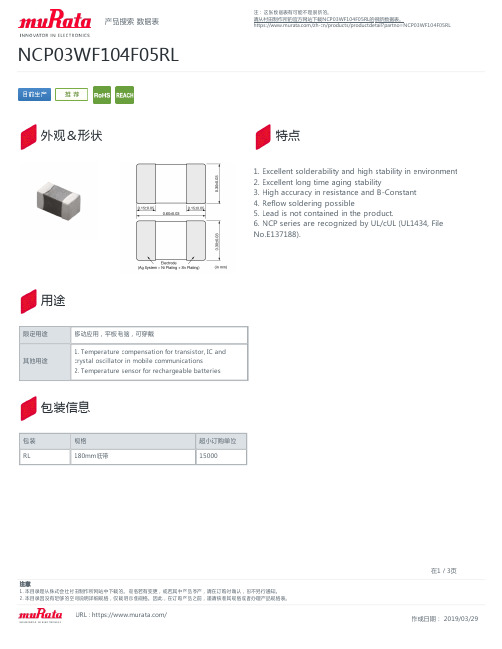
村田制作所 NCP03WF104F05RL 数据表说明书
注意 1. 本目录是从株式会社村田制作所网站中下载的。规格若有变更,或若其中产品停产,请在订购时确认,恕不另行通知。 2. 本目录因没有足够的空间说明详细规格,仅载明标准规格。因此,在订购产品之前,谨请核准其规格或者办理产品规格表。
URL : https:///
在2 / 3页 作成日期: 2019/019/03/29
包装信息
包装 RL
规格 180mm纸带
超小订购单位 15000
注意 1. 本目录是从株式会社村田制作所网站中下载的。规格若有变更,或若其中产品停产,请在订购时确认,恕不另行通知。 2. 本目录因没有足够的空间说明详细规格,仅载明标准规格。因此,在订购产品之前,谨请核准其规格或者办理产品规格表。
URL : https:///
100kΩ ±1% 4250K ±1% 4303K 4311K 4334K 5V 0.032mA 1mW/℃ -40℃ to 125℃ 0.6x0.3mm 0.2x0.1inch SMD 0.00026g
注:这张数据表有可能不是很新的。 请从村田制作所的官方网站下载NCP03WF104F05RL的很新数据表。 https:///zh-cn/products/productdetail?partno=NCP03WF104F05RL
用途
限定用途 其他用途
移动应用,平板电脑,可穿戴
1. Temperature compensation for transistor, IC and crystal oscillator in mobile communications 2. Temperature sensor for rechargeable batteries
产品搜索 数据表
NCP03WF104F05RL
y2 陶瓷 安规电容
y2 陶瓷安规电容
陶瓷安规电容(CeramicSafetyCapacitors)是一种非常重要的电子部件,用于满足严格的安全要求。
它主要由陶瓷材料组成,能够保护电子设备免受损害,其电容量为Y2型。
在绝缘材料上,它的电容量为Y2,因此被称作“Y2陶瓷安规电容”。
“Y2陶瓷安规电容”的主要用途是向电路提供稳定的耐压能力,以防止短路和过电流的发生。
Y2陶瓷安规电容的特点是具有良好的耐压能力,使用寿命也很长。
这种电容器有不同的容量和额定电压等参数,非常适合各种应用场景。
Y2陶瓷安规电容还具有防氧化,耐温,耐电压暴露,低噪音和高稳定性等特点,使其在电子产品的安全性和可靠性方面具有良好的性能。
Y2陶瓷安规电容的制造工艺不可忽视。
它的制造规格要求高,需要精密测量和控制,使得Y2陶瓷安规电容能够满足安全标准。
因此,制造Y2陶瓷安规电容需要高质量的材料,有效的制造工艺,先进的检测设备,严格的检验流程和精确的把控。
Y2陶瓷安规电容广泛应用于家用电器、电子设备、汽车材料等领域,为安全应用提供了解决方案。
它具有良好的耐压性能,良好的绝缘性能,良好的热韧性,灵活的可靠性,耐久性能好,以及寿命长等特点,可以有效保护电子设备,提高产品的可靠性。
总的来说,Y2陶瓷安规电容的可靠性和可信度是一个重要的因素,更是许多电子设备可靠性研究和评估的重要指标。
它不仅提供了有效的安全保护,而且还满足严格的安全要求,因此在电子产品上应
用比较广泛,是电子设备安全性能的重要保证。
村田制作所 电路板插件式 (DC用) EMI静噪滤波器 (EMIFIL) 说明书

Cat.No.C31C-4关于欧盟RoHS指令・本产品目录中的所有产品都符合欧盟RoHS指令。
・欧盟RoHS指令是指欧盟的“关于在电子电气设备中限制使用某些有害物质指令2002/95/EC”。
・详情请参见本公司网站“Murata's Approach for EU RoHS”(/info/rohs.html)。
12345624713646769818592目录本产品目录中的EMIFIL r 、EMIGUARD r 、“EMIFIL”和“EMIGUARD”是村田制作所的注册商标。
EMI静噪滤波器选择指南片状铁氧体磁珠开始BLM41P阻抗值为100MHz时的代表值。
2DLW5BS(AH)DLW31SNFM41PNFA31C2220NFM55PNFE61PNFL21SNFA31GNFA21S开始开始片状EMIFIL r共模扼流线圈3EMI静噪滤波器选择指南品种一览表/有效频率范围4品种一览表/有效频率范围5品种一览表/有效频率范围6..............p.21–91............p.146–148BLM03BLM02BLA31BLM31BLM41BLM18BLM21BLM15BLA2ABL01BL02RN1BL02RN2BL03RN2片状铁氧体磁珠铁氧体磁珠电感器o 片状铁氧体磁珠o 铁氧体磁珠电感器" 片状铁氧体磁珠可在几MHz到几GHz频率范围内有效。
片状铁氧体磁珠作为通用静噪元件,被广泛应用于低噪声控制。
" 片状铁氧体磁珠可在低频范围内产生微小的电感。
但是在高频,电感器的电阻分量将成为主要阻抗。
当串联接入噪声产生电路中时,电感器的电阻性阻抗将阻止噪声传播。
DC用EMI静噪滤波器 (EMIFIL r ) 概要介绍7...............p.95–99p.103–105p.114–120.............p.150–158............p.121–122NFE31P NFE61P/HNFM21P NFM31PNFM21CNFM3DCDS-6DS-9DS-9HNFA31C NFA18S806040201510C=2200pF501005001000 NFM18PNFA21S片状EMIFIL r引线型EMIFIL rT型片状EMIFIL ro片状EMIFIL ro T型片状EMIFIL ro引线型EMIFIL r" 该电容器型EMI静噪滤波器对从几MHz到几百MHz的频率具有大噪声静噪效果。
y电容技术参数
y电容技术参数
Y电容是一种安全电容,通常用于滤除差模信号,其技术参数包括额定电容量、最大工作电压、温度系数、失真因素和漏电流等。
1. 额定电容量:Y电容的额定电容量通常通过器件上的标记表示,如10nF、100nF等。
它的大小取决于电容器两极板之间的电荷储存能力。
2. 最大工作电压:这是电容器允许承受的最大电压,超过此电压可能导致电容器击穿。
在选择Y电容时,应注意其最大工作电压是否符合实际应用的需求。
3. 温度系数:这是指电容器电容值相对于温度变化的变化程度,常用ppm/℃表示。
温度系数较小的电容器,其电容值随温度变化的影响较小,适用于对电容稳定性要求较高的电路中。
4. 失真因素:这是指电容在高频电路中影响电路性能的一种现象,常用失真因数DF表示。
DF越小,电容的失真越小,相应的电容性能越好。
5. 漏电流:这是指电容器两极板之间的电流,通常用μA(微安)表示。
漏
电流直接影响Y电容的使用寿命,因此在选择Y电容时要注意其漏电流的大小。
此外,Y电容还有绝缘等级的要求,它分为Y1、Y2、Y3、Y4等不同等级。
其中,Y1耐高压大于8kV,Y2耐高压大于5kV,Y3耐高压n/a,Y4耐高压大于。
这些参数在选择和使用Y电容时都需考虑,以确保其符合实际应用需求和安全标准。
村田贴片电容规格书
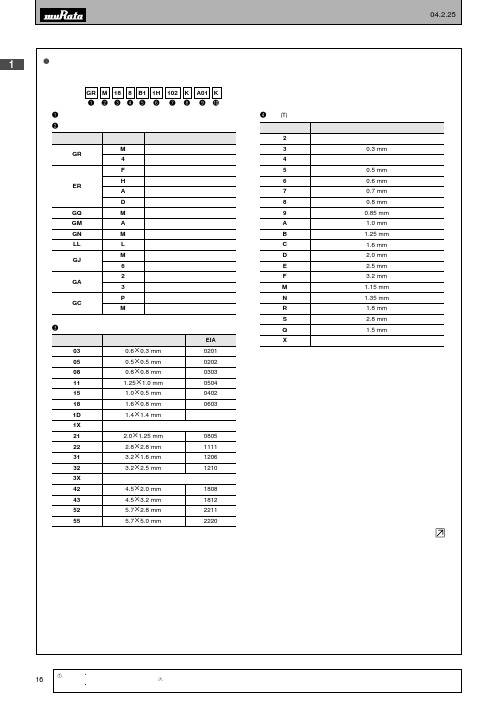
±10% ±10% +22, -56% +30, -80% +22, -82% ±15% ±15% ±15% ±15% ±22% -4700+100/-2500ppm/°C -4700+500/-1000ppm/°C
Ex.)
代号
R50
1R0
100
103
静电容量 0.5pF 1.0pF 10pF
10000pF
i静电容量允许偏差
代号 B
静电容量允许偏差 ±0.1pF
C
±0.25pF
D
±0.5pF
G
±2%
J
±5%
K
±10%
M
±20%
Z R * E24系列也可以提供。
+80%, -20%
温度特性 C∆
C∆–SL C∆
C∆–SL C∆ C∆ C∆
1206
3.2g2.5 mm
1210
按照个别规格规定。
4.5g2.0 mm
1808
4.5g3.2 mm
1812
5.7g2.8 mm
2211
5.7g5.0 mm
2220
r厚度 (T)
代号
厚度 (T)
2
2单元(排列型)
3
0.3 mm
4
4单元(排列型)
5
0.5 mm
6
0.6 mm
7
0.7 mm
8
村田芯片型号

村田芯片型号村田制作的多层陶瓷电容器芯片(Multi-Layer Ceramic Capacitors, MLCCs)是电子产品中常见的一种被广泛应用的元件。
这些电容器芯片以其小巧的尺寸、高性能和可靠性而备受推崇。
在此,我们将介绍一些村田芯片型号及其应用。
1. 村田芯片型号 GRM21BR61A106KE19L:这款芯片是一种陶瓷电容器,具有1uF的电容值。
它广泛应用于通信设备、计算机、数码产品和汽车电子等领域。
该型号的特点是体积小、频率响应快且具有低温漂移。
2. 村田芯片型号 GRM188R71H104KA93D:这是一种10uF的陶瓷电容器,适用于各种电子设备。
它具有低ESR(等效串联电阻)和低漏电流的特点,能够提供可靠的电源稳定性和滤波效果。
因此,在电源和信号处理电路中广泛应用。
3. 村田芯片型号 GRM155R60J475ME87D:这款芯片是一种4.7uF的陶瓷电容器,特别适用于移动通信设备、计算机和消费类电子产品。
它具有高电容密度和低ESR的特点,能够提供稳定的电源和滤波效果,使设备具有较好的性能和可靠性。
4. 村田芯片型号 GRM32ER71H475KA88L:这是一种4.7uF的陶瓷电容器,广泛应用于高频电路和功率管理电路。
它具有低ESR和低ESL(等效串联电感)的特点,适用于对电源稳定性和信号传输质量要求较高的应用。
5. 村田芯片型号 GRM188R61C106MAALD:这款芯片是一种10uF的陶瓷电容器,适用于各种电子设备。
它具有高电容密度和低ESR的特点,能够提供稳定的电源和滤波效果。
该型号还具有可靠性高、耐高温性能好的特点,适用于工业和汽车电子等领域。
6. 村田芯片型号 GRM155R61A475MEAAJ:这是一种4.7uF的陶瓷电容器,适用于移动通信设备、计算机和消费类电子产品。
它具有高电容密度和低ESR的特点,能够提供稳定的电源和滤波效果,同时也具有低压降和快速充电的特点,满足设备对电源质量和响应速度的要求。
安规电容 y2电容

安规电容 y2电容电容(Capacitor)是一种电子元件,它由两个或多个电极隔开而成。
可以从技术角度将它称为“电容”,也可以将它看作是在电路中连接电源和用户之间的一种绝缘元件。
本文将会介绍安规电容 Y2容,它是一种特殊类型的电容,用于有害现场以及其他特殊要求的环境中。
Y2容属于安规电容,它被认为是非常必要的,用于有害现场或者特殊要求的环境中。
它的设计特点是在部分电容的安全等级上增强,其外壳材料及构造也和普通电容不同,以满足安全要求。
在经过特殊的包装处理后,Y2容可以在可燃性和有毒物质的环境中使用。
Y2容也比普通电容具有更高的温度等级(105℃),通常使用不燃烧物质作为电容介质,能够在温度较高的环境中稳定工作。
它还比普通电容具有更高的机械强度,可以更好地抵抗外界冲击和振动,以满足在特定环境中使用的需要。
此外,Y2容在特殊要求的环境中还可以使用,例如高压、高温等环境。
Y2容的特殊性质可以满足环境温度较高的场合,比如高偏差范围的要求。
除此之外,Y2容还可以用于有毒气体和有害物质的环境中,保证安全和运行稳定。
从上述内容可以看出,Y2容是一种具有较高要求的特殊类型的电容,它主要应用于可燃性特殊场合和其他特殊要求的环境。
它具有良好的温度稳定性、优异的机械强度、安全性及其他特性,因此在有害现场以及其他特殊要求的环境中占据重要的地位。
总而言之,安规 Y2容是一种特殊类型的电容,其主要应用于有害现场以及其他特殊要求的环境中。
它被广泛应用于工业生产以及电脑系统及消费电子设备中,具有良好的温度稳定性、安全性及机械强度等特性,使其能更好地满足特定环境中使用的要求。
村田电容基本知识
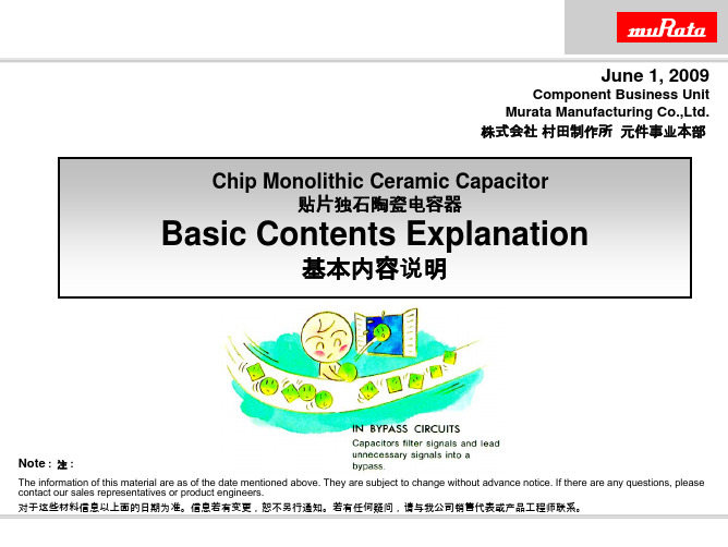
Aluminum 铝 Glass 玻璃 Mica 云母 Electrolytic Double Layer 双倍电解层
Using high purity conductive material as positive electrodes , oxidized layers on the electrodes , either liquid or solid electrolyte contacting oxidized layers as the negative electrodes.
Contents
内容
1. Material of Capacitor
电容器的材料
2. Ceramic Material and Characteristic (Class 1, Class 2)
陶瓷材料和特性
3. Construction & Manufacturing Process (MLCC)
The Wonder Stones - Ceramic
奇石 – 陶瓷
Ceramics that Store Electricity <DIELECTRIC CERAMICS> 陶瓷储存电荷 <介电陶瓷>
* The capacity to store electricity temporarily by dielectric polarization. 用介电体的极化来暂时储存电荷 * AC Passes, but DC is Stopped. (Capacitor、EMIFIL…) AC能通过,但CD被卡住了。(电容器,滤波器…)
Ceramic 陶瓷
Using Ceramic as the dielectric , metal baked with ceramic as inner electrodes , non-polarized and non-organic capacitors.
村田陶瓷电容命名规则

村田陶瓷电容命名规则摘要:I.引言- 简述村田陶瓷电容II.命名规则- 概述村田陶瓷电容的命名规则- 解释命名规则中的各个部分III.举例说明- 使用具体的村田陶瓷电容型号,解释其命名规则IV.总结- 简要总结村田陶瓷电容的命名规则正文:I.引言村田陶瓷电容是电子行业中常见的被动元器件之一。
它们以稳定性高、可靠性好、体积小等特点,被广泛应用于各种电子产品中。
对于从事电子行业的人来说,了解村田陶瓷电容的命名规则是十分必要的。
II.命名规则村田陶瓷电容的命名规则主要包括四个部分,即:字母表示名称、字母表示材料、数字表示分类、数字表示序号。
1.字母表示名称:电容器的命名以字母"C"开头,代表电容。
2.字母表示材料:村田陶瓷电容的材料主要以陶瓷为主,用字母"M"表示。
3.数字表示分类:分类代码用于表示电容的性能和结构,如1 代表普通电容,2 代表高介电常数电容等。
4.数字表示序号:序号用于表示同一分类代码下的不同产品,通常由数字和字母组成,如103 代表第一个产品,104 代表第二个产品等。
III.举例说明以村田陶瓷电容型号"CM188R71H103J01D"为例,解释其命名规则:1."C"表示电容;2."M"表示材料为陶瓷;3."188"表示分类代码,代表村田陶瓷电容的性能和结构;4."R71"表示序号,代表同一分类代码下的不同产品;5."H103"表示电容的容量,单位为皮法(pF);6."J"表示精度;7."01"表示温度系数;8."D"表示包装方式。
- 1、下载文档前请自行甄别文档内容的完整性,平台不提供额外的编辑、内容补充、找答案等附加服务。
- 2、"仅部分预览"的文档,不可在线预览部分如存在完整性等问题,可反馈申请退款(可完整预览的文档不适用该条件!)。
- 3、如文档侵犯您的权益,请联系客服反馈,我们会尽快为您处理(人工客服工作时间:9:00-18:30)。
Reference SpecificationProduct specifications in this drawing are subject to change or our products described in this drawing may be discontinued without advance notice.The parts numbers and specifications listed in this drawing are for information only. You are Engineering Section Izumo Murata Manufacturing Co.,Ltd.DATE:requested to transact the "Product Specification", before your ordering.Capacitor Division 2Type KY(Safety standard certified ceramic capacitor)Mar.29,2012Do not use these products in any Automotive Power train or Safety equipment including Battery charger for Electric Vehicles and Plug-in Hybrid.Only Murata products clearly stipulated as “for Automotive use” on its product specification can be used for automobile applications such as Power train and Safety equipment.CAUTION1. OPERATING VOLTAGE6. SOLDERINGWhen soldering this product to a PCB/PWB, do not exceed the solder heat resistance specification of the capacitor. Subjecting this product to excessive heating could melt the internal junction solder and may result in thermal shocks that can crack the ceramic element.When soldering capacitor with a soldering iron, it should be performed in following conditions.Temperature of iron-tip : 400 °C max.Soldering iron wattage : 50W max.Soldering time : 3.5s max.7. BONDING, RESIN MOLDING AND COATINGIn case of bonding, molding or coating this product, verify that these processes do not affect thequality of capacitor by testing the performance of the bonded, molded or coated product in theintended equipment.In case of the amount of applications, dryness / hardening conditions of adhesives and moldingresins containing organic solvents (ethyl acetate, methyl ethyl ketone, toluene, etc.) are unsuitable, the outer coating resin of a capacitor is damaged by the organic solvents and it may result, worst case, in a short circuit.The variation in thickness of adhesive, molding resin or coating may cause a outer coating resin cracking and/or ceramic element cracking of a capacitor in a temperature cycling.8. TREATMENT AFTER BONDING, RESIN MOLDING AND COATINGWhen the outer coating is hot (over 100 ℃) after soldering, it becomes soft and fragile.So please be careful not to give it mechanical stress.Failure to follow the above cautions may result, worst case, in a short circuit and cause fuming or partial dispersion when the product is used.9. OPERATING AND STORAGE ENVIRONMENTThe insulating coating of capacitors does not form a perfect seal; therefore, do not use or storecapacitors in a corrosive atmosphere, especially where chloride gas, sulfide gas, acid, alkali, salt or the like are present. And avoid exposure to moisture. Before cleaning, bonding, or moldingthis product, verify that these processes do not affect product quality by testing the performance of a cleaned, bonded or molded product in the intended equipment. Store the capacitors where thetemperature and relative humidity do not exceed -10 to 40 °C and 15 to 85%.Use capacitors within 6 months after delivered. Check the solderability after 6 months or more.10. LIMITATION OF APPLICATIONSPlease contact us before using our products for the applications listed below which require especially high reliability for the prevention of defects which might directly cause damage to the third party’s life, body or property.1. Aircraft equipment2. Aerospace equipment3. Undersea equipment4. Power plant control equipment5. Medical equipment6. Transportation equipment (vehicles, trains, ships, etc.)7. Traffic signal equipment8. Disaster prevention / crime prevention equipment9. Data-processing equipment exerting influence on public10. Application of similar complexity and/or reliability requirements to the applications listedin the above.NOTICE1. CLEANING (ULTRASONIC CLEANING)To perform ultrasonic cleaning, observe the following conditions.Rinse bath capacity : Output of 20 watts per liter or less.Rinsing time : 5 min maximum.Do not vibrate the PCB/PWB directly.Excessive ultrasonic cleaning may lead to fatigue destruction of the lead wires.2. CAPACITANCE CHANGE OF CAPACITORS⋅ Class 1 capacitorsCapacitance might change a little depending on a surrounding temperature or an applied voltage.Please contact us if you use for the strict time constant circuit.⋅ Class 2 and 3 capacitorsClass 2 and 3 capacitors like temperature characteristic B, E and F have an aging characteristic, whereby the capacitor continually decreases its capacitance slightly if the capacitor leaves for a long time. Moreover, capacitance might change greatly depending on a surrounding temperature or an applied voltage. So, it is not likely to be able to use for the time constant circuit.Please contact us if you need a detail information.3. PERFORMANCE CHECK BY EQUIPMENTBefore using a capacitor, check that there is no problem in the equipment's performance and the specifications.Generally speaking, CLASS 2 ceramic capacitors have voltage dependence characteristics and temperature dependence characteristics in capacitance. So, the capacitance value may change depending on the operating condition in a equipment. Therefore, be sure to confirm the apparatus performance of receiving influence in a capacitance value change of a capacitor, such as leakage current and noise suppression characteristic.Moreover, check the surge-proof ability of a capacitor in the equipment, if needed, because the surge voltage may exceed specific value by the inductance of the circuit.NOTE1.Please make sure that your product has been evaluated in view of your specifications with ourproduct being mounted to your product.2.You are requested not to use our product deviating from this specification.1. ApplicationThis specification is applied to following safety standard certified ceramic capacitor Type KY. Type KY is Safety Standard Certified disc ceramic capacitor of Class X1,Y2.Approval standard and certified numberStandard number *Certified number AC Rated volt.V(r.m.s.)ULUL1414E37921250 UL60384-14 300CSA E384-14 1283280250 VDE IEC 60384-14, EN 60384-14 40006273 250BSI EN 60065 (8.8,14.2),IEC 60384-14,EN 60384-14KM 37901 250SEMKOIEC 60384-14,EN 60384-14 812168 250DEMKO 314115250FIMKO 24197250NEMKO P0*******250ESTI 08.0710250NSW IEC 60384-14, AS3250 6824 250*Above Certified number may be changed on account of the revision of standards andthe renewal of certification.2. Rating2-1. Operating temperature range-25 ∼ +125°C(In case of UL1414 standard use : -25 ~ +85°C)2-2. Part number configurationex.) DE2 E3 KY 472 M A2 B M01Product Temperature Type Capacitance Capacitance Lead Packing Individualcode characteristic name tolerance code style code specification• Product codeDE2 denotes class X1,Y2.•Temperature characteristicCode Temperaturecharacteristic1X SLB3 BE3 EF3 FPlease confirm detailed specification on [ Specification and test methods ].• Type nameThis denotes safety certified type name Type KY.• CapacitanceThe first two digits denote significant figures ; the last digit denotes the multiplier of 10 in pF.ex.) In case of 472.47×102 = 4700pF: (Made in Taiwan), (Made in Thailand)0D4. Part number listUnit : mmT.C.Cap. (pF)Cap. tol.Customer Part NumberMurata Part NumberDimension (mm)LeadcodePackqty.(pcs)D T F dSL 10±5% DE21XKY100JA2BM01 8.0 5.0 5.00.6A2250SL 10±5% DE21XKY100JA3BM02 8.0 5.07.50.6A3250SL 15±5% DE21XKY150JA2BM01 8.0 5.0 5.00.6A2250SL 15±5% DE21XKY150JA3BM02 8.0 5.07.50.6A3250SL 22±5% DE21XKY220JA2BM01 8.0 5.0 5.00.6A2250SL 22±5% DE21XKY220JA3BM02 8.0 5.07.50.6A3250SL 33±5% DE21XKY330JA2BM01 8.0 5.0 5.00.6A2250SL 33±5% DE21XKY330JA3BM02 8.0 5.07.50.6A3250SL 47±5% DE21XKY470JA2BM01 8.0 5.0 5.00.6A2250SL 47±5% DE21XKY470JA3BM02 8.0 5.07.50.6A3250SL 68±5% DE21XKY680JA2BM01 8.0 5.0 5.00.6A2250SL 68±5% DE21XKY680JA3BM02 8.0 5.07.50.6A3250B 100±10% DE2B3KY101KA2BM01 7.0 5.0 5.00.6A2500B 100±10% DE2B3KY101KA3BM02 7.0 5.07.50.6A3250B 150±10% DE2B3KY151KA2BM01 7.0 5.0 5.00.6A2500B 150±10% DE2B3KY151KA3BM02 7.0 5.07.50.6A3250B 220±10% DE2B3KY221KA2BM01 7.0 5.0 5.00.6A2500B 220±10% DE2B3KY221KA3BM02 7.0 5.07.50.6A3250B 330±10% DE2B3KY331KA2BM01 7.0 5.0 5.00.6A2500B 330±10% DE2B3KY331KA3BM02 7.0 5.07.50.6A3250B 470±10% DE2B3KY471KA2BM01 7.0 5.0 5.00.6A2500B 470±10% DE2B3KY471KA3BM02 7.0 5.07.50.6A3250B 680±10% DE2B3KY681KA2BM01 8.0 5.0 5.00.6A2250B 680±10% DE2B3KY681KA3BM02 8.0 5.07.50.6A3250E 1000±20% DE2E3KY102MA2BM01 7.0 5.0 5.00.6A2500E 1000±20% DE2E3KY102MA3BM02 7.0 5.07.50.6A3250E 1500±20%DE2E3KY152MA2BM01 7.05.05.00.6A2500Unit : mmT.C.Cap. (pF)Cap. tol.Customer Part NumberMurata Part NumberDimension (mm)LeadcodePackqty.(pcs)D T F dE 1500±20% DE2E3KY152MA3BM02 7.0 5.07.50.6A3250E 2200±20% DE2E3KY222MA2BM01 8.0 5.0 5.00.6A2250E 2200±20% DE2E3KY222MA3BM02 8.0 5.07.50.6A3250E 3300±20% DE2E3KY332MA2BM01 9.0 5.0 5.00.6A2250E 3300±20% DE2E3KY332MA3BM02 9.0 5.07.50.6A3250E 4700±20% DE2E3KY472MA2BM01 10.0 5.0 5.00.6A2250E 4700±20% DE2E3KY472MA3BM02 10.0 5.07.50.6A3250F 10000±20% DE2F3KY103MA3BM02 14.0 5.07.50.6A3200SL 10±5% DE21XKY100JB2BM01 8.0 5.0 5.00.6B2500SL 10±5% DE21XKY100JB3BM02 8.0 5.07.50.6B3500SL 15±5% DE21XKY150JB2BM01 8.0 5.0 5.00.6B2500SL 15±5% DE21XKY150JB3BM02 8.0 5.07.50.6B3500SL 22±5% DE21XKY220JB2BM01 8.0 5.0 5.00.6B2500SL 22±5% DE21XKY220JB3BM02 8.0 5.07.50.6B3500SL 33±5% DE21XKY330JB2BM01 8.0 5.0 5.00.6B2500SL 33±5% DE21XKY330JB3BM02 8.0 5.07.50.6B3500SL 47±5% DE21XKY470JB2BM01 8.0 5.0 5.00.6B2500SL 47±5% DE21XKY470JB3BM02 8.0 5.07.50.6B3500SL 68±5% DE21XKY680JB2BM01 8.0 5.0 5.00.6B2500SL 68±5% DE21XKY680JB3BM02 8.0 5.07.50.6B3500B 100±10% DE2B3KY101KB2BM01 7.0 5.0 5.00.6B2500B 100±10% DE2B3KY101KB3BM02 7.0 5.07.50.6B3500B 150±10% DE2B3KY151KB2BM01 7.0 5.0 5.00.6B2500B 150±10% DE2B3KY151KB3BM02 7.0 5.07.50.6B3500B 220±10% DE2B3KY221KB2BM01 7.0 5.0 5.00.6B2500B 220±10% DE2B3KY221KB3BM02 7.0 5.07.50.6B3500B 330±10%DE2B3KY331KB2BM01 7.05.05.00.6B2500Unit : mmT.C. Cap.(pF)Cap.tol.Customer Part Number Murata Part NumberDimension (mm) LeadcodePackqty.(pcs)D T F dB 330±10% DE2B3KY331KB3BM02 7.0 5.07.50.6B3500 B 470±10% DE2B3KY471KB2BM01 7.0 5.0 5.00.6B2500 B 470±10% DE2B3KY471KB3BM02 7.0 5.07.50.6B3500 B 680±10% DE2B3KY681KB2BM01 8.0 5.0 5.00.6B2500 B 680±10% DE2B3KY681KB3BM02 8.0 5.07.50.6B3500 E 1000±20% DE2E3KY102MB2BM01 7.0 5.0 5.00.6B2500 E 1000±20% DE2E3KY102MB3BM02 7.0 5.07.50.6B3500 E 1500±20% DE2E3KY152MB2BM01 7.0 5.0 5.00.6B2500 E 1500±20% DE2E3KY152MB3BM02 7.0 5.07.50.6B3500 E 2200±20% DE2E3KY222MB2BM01 8.0 5.0 5.00.6B2500 E 2200±20% DE2E3KY222MB3BM02 8.0 5.07.50.6B3500 E 3300±20% DE2E3KY332MB2BM01 9.0 5.0 5.00.6B2500 E 3300±20% DE2E3KY332MB3BM02 9.0 5.07.50.6B3500 E 4700±20% DE2E3KY472MB2BM01 10.0 5.0 5.00.6B2500E 4700±20% DE2E3KY472MB3BM02 10.0 5.07.50.6B3500F 10000±20% DE2F3KY103MB3BM02 14.0 5.07.50.6B3250Unit : mmT.C. Cap.(pF)Cap.tol.Customer Part Number Murata Part NumberDimension (mm) LeadcodePackqty.(pcs)D T F d PSL 10±5% DE21XKY100JN2AM018.0 5.0 5.00.612.7N21000 SL 10±5% DE21XKY100JN3AM028.0 5.07.50.615.0N3900 SL 15±5% DE21XKY150JN2AM018.0 5.0 5.00.612.7N21000 SL 15±5% DE21XKY150JN3AM028.0 5.07.50.615.0N3900 SL 22±5% DE21XKY220JN2AM018.0 5.0 5.00.612.7N21000 SL 22±5% DE21XKY220JN3AM028.0 5.07.50.615.0N3900 SL 33±5% DE21XKY330JN2AM018.0 5.0 5.00.612.7N21000 SL 33±5% DE21XKY330JN3AM028.0 5.07.50.615.0N3900 SL 47±5% DE21XKY470JN2AM018.0 5.0 5.00.612.7N21000 SL 47±5% DE21XKY470JN3AM028.0 5.07.50.615.0N3900 SL 68±5% DE21XKY680JN2AM018.0 5.0 5.00.612.7N21000 SL 68±5% DE21XKY680JN3AM028.0 5.07.50.615.0N3900 B 100±10% DE2B3KY101KN2AM017.0 5.0 5.00.612.7N21000 B 100±10% DE2B3KY101KN3AM027.0 5.07.50.615.0N3900 B 150±10% DE2B3KY151KN2AM017.0 5.0 5.00.612.7N21000 B 150±10% DE2B3KY151KN3AM027.0 5.07.50.615.0N3900 B 220±10% DE2B3KY221KN2AM017.0 5.0 5.00.612.7N21000 B 220±10% DE2B3KY221KN3AM027.0 5.07.50.615.0N3900 B 330±10% DE2B3KY331KN2AM017.0 5.0 5.00.612.7N21000 B 330±10% DE2B3KY331KN3AM027.0 5.07.50.615.0N3900 B 470±10% DE2B3KY471KN2AM017.0 5.0 5.00.612.7N21000 B 470±10% DE2B3KY471KN3AM027.0 5.07.50.615.0N3900 B 680±10% DE2B3KY681KN2AM018.0 5.0 5.00.612.7N21000 B 680±10% DE2B3KY681KN3AM028.0 5.07.50.615.0N3900 E 1000±20% DE2E3KY102MN2AM017.0 5.0 5.00.612.7N21000 E 1000±20% DE2E3KY102MN3AM027.0 5.07.50.615.0N3900 E 1500±20% DE2E3KY152MN2AM017.0 5.0 5.00.612.7N21000Unit : mmT.C. Cap.(pF)Cap.tol.Customer Part Number Murata Part NumberDimension (mm) LeadcodePackqty.(pcs)D T F d PE 1500±20% DE2E3KY152MN3AM027.0 5.07.50.615.0N3900 E 2200±20% DE2E3KY222MN2AM018.0 5.0 5.00.612.7N21000 E 2200±20% DE2E3KY222MN3AM028.0 5.07.50.615.0N3900 E 3300±20% DE2E3KY332MN2AM019.0 5.0 5.00.612.7N21000 E 3300±20% DE2E3KY332MN3AM029.0 5.07.50.615.0N3900 E 4700±20% DE2E3KY472MN2AM0110.0 5.0 5.00.612.7N21000E 4700±20% DE2E3KY472MN3AM0210.0 5.07.50.615.0N3900F 10000±20% DE2F3KY103MN3AM0214.0 5.07.50.615.0N39005. Specification and test methodsNo. Item Specification Testmethod1 Appearance and dimensions No marked defect on appearanceform and dimensions.Please refer to [Part number list]. The capacitor should be inspected by naked eyes for visible evidence of defect.Dimensions should be measured with slide calipers.2 Marking To be easily legible. The capacitor should be inspected by naked eyes.3 Dielectricstrength Between leadwiresNo failure. The capacitor should not be damaged whenAC2000V(r.m.s.) [in case of individual specification:M01] or AC2600V(r.m.s.) [in case of individualspecification:M02] <50/60Hz> is applied betweenthe lead wires for 60 s.(Charge/Discharge current ≤ 50mA.)BodyinsulationNo failure. First, the terminals of the capacitor should beconnected together.Then, a metal foil shouldbe closely wrapped aroundthe body of the capacitorto the distance ofabout 3 to 4mmfrom each terminal.Then, the capacitor should be inserted into acontainer filled with metal balls of about 1mmdiameter. Finally, AC2600V (r.m.s.)<50/60Hz> isapplied for 60 s between the capacitor lead wiresand metal balls.(Charge/Discharge current ≤ 50mA.)4 Insulation Resistance (I.R.) 10000MΩ min. The insulation resistance should be measuredwith DC500±50V within 60±5 s of charging.The voltage should be applied to the capacitorthrough a resistor of 1MΩ.5 Capacitance Within specified tolerance. The capacitance should be measured at 20°C with1±0.1kHz(Char. SL :1±0.1MHz)and AC5V(r.m.s.)max..6 Q Char. SL :400+20C*2min.(30pF under)1000min. (30pF min.) The dissipation factor and Q should be measured at 20°C with 1±0.1kHz(Char. SL : 1±0.1MHz) and AC5V(r.m.s.) max..Dissipation Factor (D.F.) Char. B, E : 2.5% max.Char. F : 5.0% max.7 Temperaturecharacteristic Char. SL : +350 to –1000 ppm/°C(Temp. range : +20 to +85°C )Char. B : Within ±10 %Char. E : Within +20/-55%Char. F : Within +30/-80%(Temp. range : -25 to +85°C ) The capacitance measurement should be made at each step specified in Table.*2 ‘’C’’ expresses nominal capacitance value(pF)Step 1 2 3 4 5 Temp.(°C) 20±2-25±220±2 85±2 20±2MetalfoilMetalballsAbout3 to4 mm8 Active flammability The cheese-cloth should not be on fire. The capacitors should be individually wrapped inat least one but more than two complete layers ofcheese-cloth. The capacitor should be subjected to 20 discharges. The interval between successive discharges should be 5 s. The UAc should be maintained for 2min after the last discharge.C1,2 : 1µF ±10%, C3 : 0.033µF ±5% 10kV L1 to L4 : 1.5mH ±20% 16A Rod core choke R : 100Ω±2%, Ct : 3µF ±5% 10kVUAc : UR ±5% UR : Rated working voltage Cx : Capacitor under test F : Fuse, Rated 10AUt : Voltage applied to Ct9 Robustness of terminations Tensile Lead wire should not cut off. Capacitor should not be broken. Fix the body of capacitor, apply a tensile weightgradually to each lead wire in the radial direction ofcapacitor up to 10N and keep it for 10±1 s.Bending With the termination in its normal position, thecapacitor is held by its body in such a manner that the axis of the termination is vertical; a massapplying a force of 5N is then suspended from the end of the termination.The body of the capacitor is then inclined, within a period of 2 to 3 s, through an angle of about 90° in the vertical plane and thenreturned to its initial position over the same period of time; this operation constitutes one bend.One bend immediately followed by a second bend in the opposite direction.10 Vibration resistance Appearance No marked defect. The capacitor should be firmly soldered to thesupporting lead wire and vibration which is 10 to 55Hz in the vibration frequency range,1.5mm in total amplitude, and about 1min in the rate of vibration change from 10Hz to 55Hz and back to 10Hz is applied for a total of 6 h; 2 h each in 3 mutually perpendicular directions. Capacitance Within the specified tolerance.Q Char. SL :400+20C*2min.(30pF under)1000min. (30pF min.)D.F. Char. B, E : 2.5% max.Char. F : 5.0% max.11 Solderability of leads Lead wire should be soldered with uniformly coated on the axial direction over 3/4 of the circumferential direction. The lead wire of a capacitor should be dipped intoa ethanol solution of 25wt% rosin and then into molten solder for 2±0.5 s. In both cases the depth of dipping is up to about 1.5 to 2.0mm from theroot of lead wires. Temp. of solder :245±5°C Lead Free Solder (Sn-3Ag-0.5Cu) 235±5°C H63 Eutectic Solder*2"C" expresses nominal capacitance value(pF)12 Soldering effect (Non-preheat) Appearance No marked defect. Solder temperature: 350±10°C or 260±5°CImmersion time : 3.5±0.5 s(In case of 260±5°C : 10±1 s) The depth of immersion is up to about1.5 to2.0mm from the root of lead wires.Pre-treatment : Capacitor should be stored at 85±2°C for 1 h, then placed at*1room condition for 24±2 h before initial measurements. Post-treatment : Capacitor should be stored for 1to 2 h at *1room condition.Capacitance change Within ±10% I.R. 1000M Ω min. Dielectric strengthPer item 313 Soldering effect (On-preheat) Appearance No marked defect. First the capacitor should be stored at 120+0/-5°Cfor 60+0/-5 s. Then, as in figure, the lead wires should be immersed solder of 260+0/-5°C up to 1.5 to 2.0mm from the root of terminal for 7.5+0/-1 s.Pre-treatment : Capacitor should be stored at 85±2°C for 1 h, then placed at*1room condition for 24±2 h before initial measurements.Post-treatment : Capacitor should be stored for 1 to2 h at *1room condition.Capacitance changeWithin ±10%I.R. 1000M Ω min.Dielectric strengthPer item 314 Flame test The capacitor flame discontinue as follows. The capacitor should be subjected to appliedflame for 15 s. and then removed for 15 s until 5cycle.15 Passive flammability The burning time should not be exceeded the time 30 s. The tissue paper should not ignite.The capacitor under test should be held in the flamein the position which best promotes burning. Time of exposure to flame is for 30 s.Length of flame : 12±1mmGas burner : Length 35mm min.Inside Dia. 0.5±0.1mm Outside Dia. 0.9mm max. Gas : Butane gas Purity 95% min.*1"room condition" Temperature: 15 to 35°C, Relative humidity: 45 to 75%, Atmospheric pressure: 86 to 106kPa200±5mm45° Flame About 8mm Capacitor Gas burnerAbout 10mm thick boardTissue Cycle Time1 to 430 s max. 5 60 s max.16 Humidity (Under steady state) Appearance No marked defect. Set the capacitor for 500±12 h at 40±2°C in 90 to95% relative humidity. Post-treatment : Capacitor should be stored for 1to 2 h at *1room condition. Capacitance change Char. SL : Within ±5% Char. B : Within ±10%Char. E, F : Within ±15% Q Char. SL :275+5/2C*2min.(30pF under) 350min. (30pF min.)D.F. Char. B, E : 5.0% max.Char. F : 7.5% max.I.R. 3000M Ω min. Dielectric strengthPer item 3 17 Humidity loading Appearance No marked defect. Apply the rated voltage for 500±12 h at 40±2°C in90 to 95% relative humidity. Post-treatment : Capacitor should be stored for 1to 2 h at *1room condition. Capacitance change Char. SL : Within ±5% Char. B : Within ±10%Char. E, F : Within ±15% Q Char. SL :275+5/2C*2min.(30pF under) 350min. (30pF min.)D.F. Char. B, E : 5.0% max.Char. F : 7.5% max.I.R. 3000M Ω min. Dielectric strengthPer item 3 18 Life Appearance No marked defect. Impulse voltageEach individual capacitor should be subjected to a 5kV impulses for three times. Then the capacitors are applied to life test.The capacitors are placed in a circulating air oven for a period of 1000 h.The air in the oven is maintained at a temperature of 125+2/-0 °C, and relative humidity of 50% max.. Throughout the test, the capacitors are subjected to a AC425V(r.m.s.)<50/60Hz> alternating voltage of mains frequency, except that once each hour the voltage is increased to AC1000V(r.m.s.) for 0.1 s.Post-treatment : Capacitor should be stored for 1to 2 h at *1room condition.Capacitance changeWithin ±20%I.R. 3000M Ω min.Dielectric strengthPer item 319 Temperature and immersion cycle Appearance No marked defect. The capacitor should be subjected to5 temperature cycles, then consecutively to 2 immersion cycles.<Temperature cycle>Cycle time : 5 cycle <Immersion cycle>Cycle time : 2 cyclePre-treatment : Capacitor should be stored at 85±2°C for 1 h, then placed at*1room condition for 24±2 h. Post-treatment : Capacitor should be stored for24±2 h at *1room condition.Capacitance change Char. SL : Within ±5%Char. B : Within ±10%Char. E, F: Within ±20% Q Char. SL : 275+5/2C*2min.(30pF under) 350min. (30pF min.) D.F. Char. B, E : 5.0% max. Char. F : 7.5% max. I.R. 3000M Ω min. Dielectric strengthPer item 3*1"room condition" Temperature: 15 to 35°C, Relative humidity: 45 to 75%, Atmospheric pressure: 86 to 106kPa *2"C" expresses nominal capacitance value(pF)Step Temperature(°C) TimeImmersion water 1+65+5/-0 15 minClean water 20±3 15 minSalt waterStep Temperature(°C) Time 1 -25+0/-3 30 min2 Room temp.3 min3 +125+3/-0 30 min4 Room temp. 3 min Front time (T1) = 1.2μs=1.67T Time to half-value (T2) = 50μsAmmo pack taping type (Packing style code : A) Unit : mm 340 max.125 max. 270 max. Partition Polyethylene bag Capacitor Base tape Hold down tapeHold down tape upper7-1. Dimension of capacitors on tapeVertical crimp taping type < Lead code : N2 >Pitch of component 12.7mm / Lead spacing 5.0mmUnit : mmItem CodeDimensions RemarksPitch of component P 12.7±1.0Pitch of sprocket hole P0 12.7±0.3Lead spacingF 5.0±Length from hole center to component center P2 6.35±1.3 Deviation of progress directionLength from hole center to lead P1 3.85±0.7 Body diameterDPlease refer to [Part number list ].Deviation along tape, left or right ∆S 0±1.0 They include deviation by lead bend . Carrier tape width W 18.0±0.5Position of sprocket holeW1 9.0±0.5 Deviation of tape width directionLead distance between reference and bottom planesH0 18.0±Protrusion length +0.5∼−1.0Diameter of sprocket hole φD0 4.0±0.1 Lead diameter φd 0.60±0.05 Total tape thicknesst1 0.6±0.3 They include hold down tape thickness.Total thickness, tape and lead wire t2 1.5 max. Deviation across tape, front ∆h11.0 max.Deviation across tape, rear ∆h2Portion to cut in case of defect L 11.0±Hold down tape width W0 11.5 min.Hold down tape position W2 1.5±1.5Coating extension on lead e Up to the end of crimpBody thicknessTPlease refer to [Part number list ].2.001.0∗0.80.2Vertical crimp taping type < Lead code : N3 >Pitch of component 15.0mm / Lead spacing 7.5mmUnit : mmItem CodeDimensionsRemarksPitch of component P 15.0±2.0Pitch of sprocket hole P0 15.0±0.3 Lead spacingF 7.5±1.0 Length from hole center to component center P2 7.5±1.5 Deviation of progress directionLength from hole center to lead P1 3.75±1.0 Body diameterDPlease refer to [ Part number list ].Deviation along tape, left or right ∆S 0±2.0 They include deviation by lead bend . Carrier tape width W 18.0±0.5Position of sprocket holeW1 9.0±0.5Deviation of tape width directionLead distance between reference and bottom planesH0 18.0±Protrusion length +0.5∼−1.0Diameter of sprocket hole φD0 4.0±0.1 Lead diameter φd 0.60±0.05 Total tape thicknesst1 0.6±0.3 They include hold down tape thickness.Total thickness, tape and lead wire t2 1.5 max. Deviation across tape, front ∆h12.0 max.Deviation across tape, rear ∆h2Portion to cut in case of defect L 11.0±Hold down tape width W0 11.5 min.Hold down tape position W2 1.5±1.5Coating extension on lead e Up to the end of crimpBody thicknessTPlease refer to [ Part number list ].2.01.0∗JEED41X4-0152ape are spliced•Base tape and adhesive tape should be spliced with splicing tape.Hold down tape Base tape W Unit : mm Progress direction in production line Hold down tape Base tape Cellophane tape About 30 to 50Progress direction Hold down tape Base tape 20 to 60No lifting for the direction of。
