griwind新风系统面板说明书
格拉尔德通风机操作指南说明书

Chapter 3 – Maintenance, Page 3-1Operator Cleaning and MaintenanceOverviewTo maintain the Gaylord Ventilator in good working order, and to keep the system operating at optimum efficiency, preventive maintenance, using the following schedule should be performed.Important Note: Ventilators incorporating UV Lamps require special maintenance as shown on Page 3-4. Some of the required maintenance on Ventilators with UV can be performed by the operator. However, direct exposure to UV light is hazardous to your skin and eyes and contact with live electrical components poses a significant risk of shock or death.Daily Cleaning and MaintenanceAt the end of the each cooking day, or at periodic intervals, depending upon the type of cooking, the XGS Extractors and Grease Drawer must be removed and cleaned. The Grease Gutter should also be wiped out. CAUTION: Before proceeding with cleaning, check to see that the exhaust fan is shut off and the cooking equipment is cool. To clean proceed as follows:1. Remove Extractors: CAUTION: Care should be taken when removing the Extractors, especially overfryers. It is recommended that the cooking equipment be cooled down and the fryers be covered prior to removing the Extractors. They may be removed by hand or by use of an optional Extractor Removal Tool (Refer to Figure 3-2-1). To remove, lift up slightly on the Extractor and pull out from the bottom, then straight down.2. The Extractors may be cleaned either by using a dishwasher or by soaking in a deep well sink using hotwater with a degreasing detergent, then scrubbed and rinsed. Gaylord Formula G-510EF detergent is highly recommended for this application. Refer to Page 3-7 for details.3. With the Extractors removed inspect the back wall and the underside of the exhaust plenum. If neces-sary clean with hot detergent water.4. Wipe and clean the Grease Gutter.5. Remove and empty the Grease Drawer, clean and replace.6. Replace the filters or Extractors. Note: Filters and Extractors must be installed with the openings run-ning vertical as shown in Figure 3-2-2. Gaylord XGS Extractors have an arrow stamped on the face designating “UP”.Additional Cleaning Instructions for UVi Series VentilatorsThe UV Lamps will develop a coating of dust, and sometimes debris that will have to be wiped away. The Lamps should be inspected weekly and cleaned when necessary. To clean proceed as follows:1. Remove all the Extractors.2. Reach up through the opening and carefully wipe each Lamp with a non abrasive wet cloth with milddetergent. Remove all the dust, grease or other contaminants that may have collected on the Lamp.3. Replace the Extractors.Note: Failure to maintain the cleanliness of the Lamps will reduce the UV systems ability to reduce the build-up of grease and debris on the exhaust ducts and fans.Figure 3-2-2 Gaylord Model XGS ExtractorChapter 3 – Maintenance, Page 3-3Operator Cleaning and Maintenance – Cont.Code Required Inspection and CleaningThe National Fire Protection Association Standard NFPA-96 (Standard for Ventilation Control and Fire Pro-tection of Commercial Cooking Operations) requires that hoods (Ventilators), ducts and exhaust fans must be inspected by a properly trained, qualified and certified company or person(s) in accordance with the following table.Table T-3-3-1Upon inspection, if found to be contaminated with deposits from grease laden vapors, the entire exhaust system shall be cleaned by a properly trained, qualified, and certified company or person(s) acceptable to the authority having jurisdiction.When a vent cleaning service is used, a certificate showing date of inspection or cleaning shall be main-tained on the premises. After cleaning is completed, the vent cleaning contractor shall place or display within the kitchen area a label indicating the date cleaned and the name of the servicing company. It shall also indicate any area not cleaned.CAUTION regarding pressure washing or steam cleaning: If the Ventilator includes a UV System the UV Modules must be removed prior to pressure washing or steam cleaning.Chapter 3 - Maintenance, Page 3-4CAUTION: Preventive maintenance and repairs made to the UV System as outlined on pages 3-3 through 3-5 MUST be performed by Gaylord Certified Service Agent. For a list of Gaylord Certified Service Agen-cies (CSA’s) visit and go to “Service Agencies”.WARNING: Certified Service Agent maintenance and repair warning. Do not defeat any Safety Interlocks during cleaning, maintenance and repair.Safety RequirementsCaution: Exposure to UV light is harmful to skin and eyes. Before servicing or repairing any of the UV System read and perform the following safety requirements.OverviewThe ELX-UVi Ventilator is equipped with light attenuation barriers and Safety Interlocks to protect opera-tors from direct exposure to UV light. All safety precautions called for in this manual must be followed to avoid the potential for harm to service personnel or operators.As with many types of technology if it is not used properly and/or proper precautions are not taken there is the potential for injury or harm. This is especially true of UV light due to the fact that it does not physically hurt at the time of exposure. UV generated in these Ventilators is greater than what results from direct exposure to the sun. Under no circumstances is it acceptable to view the lighted lamps without proper eye protection or expose bare skin directly to the light. All safety precautions called for in this manual must be followed to avoid the potential for harm to service personnel and/or operators.Personal Protective Equipment1. Eye protection that prevents 100% of UV light from being transmitted through the lens must be wornat all times when replacing the UV Lamps on any ELX-UVi Ventilator that is energized and/or has the potential to be energized and expose personnel to UV light.2. Whenever service work is performed it is recommended that long sleeve shirts and pants be worn tominimize the potential for inadvertent exposure of the skin to UV light.Preventive MaintenanceThe following Preventive Maintenance items must be performed by a trained and qualified Certified Ser-vice Agency at a frequency shown on page 3-2, Table T-3-2-1, EXHAUST SYSTEM INSPECTION SCHEDULE. These tasks involve potential exposure to high doses of UV light and live electrical components. There is a risk of shock, injury and/or death from contact with live electrical components.1. Testing UV Lamps and Ballasts(For these tests all XGS Extractors must be in place, the Extractor Access Doors closed and all UVModule Access Doors in place and latched.)a. Turn on the exhaust fan at the Gaylord Command Center. The “UV i SYSTEM ON” green Status Light in each Ventilator Section should be on. In addition to the Status Lights on the Ventilator, the Gaylord Command Center should display text indicating the similar message as the Status Lights.Chapter 3 - Maintenance, Page 3-5Testing UV Lamps and Ballasts - Cont.b. If the yellow “UV i LAMP FAILURE” Status Light is on it indicates that one or more of the UV Lamps are not operating. To troubleshoot and replace a lamp refer to the Troubleshooting page 4-4, and Testing and Repair section of this manual beginning on page 5-13.c. If the blue “UVi SYSTEM STANDBY” Status Light is on it indicates that one or more XGS Extractors are not in place and/or one or more UV Module Access Doors have not been closed properly or the internal temperature of the Ballast Box has exceeded 118° F. which activates the High Temperature Shutdown Controller. Refer to page 5-26 for troubleshooting and corrective action for the Tempera - 2. Inspect and Clean UV Modules a . Turn off the exhaust fan at the Command Center. b. Open the UV Module Access Door(s) (refer to Figure 2-10-2). c. Disconnect the UV Module Lamp Ballast Connector.d. Remove the UV Module(s) from the Ventilator. (Caution: Care must be taken to keep the connector from hitting the lamps while removing the module.) e . Using a damp non abrasive cloth and mild detergent, wipe down the Lamps and Lamp Housing. Lamps should be free of all grease and debris.f. Carefully inspect the UV Module Access Door and replace the gasket as needed to ensure a good seal.g. Reinstall the UV Module(s) being careful to not hit the Lamps.h. Reconnect the UV Module Lamp Ballast Connector.i. Close the UV Module Access Door(s).3. Test Safety Interlocks for the XGS Extractors (Pressure Switches) (Caution: For the following tests Polycarbonate Safety Glasses must be worn.) a . Turn on the exhaust fan at the Command Center. The “UVi SYSTEM ON ” green Status Light in each Ventilator Section should be on.UVi SYSTEM ON SYSTEM STATUSChapter 3 - Maintenance, Page 3-6Test Safety Interlocks for the XGS Extractors (Pressure Switches) - Cont.b. Open the Extractor Access Door at the left end of the Ventilator remove one XGS Extractor. The blue “UVi System Standby” Status Light should come on. If this action does not occur, immediately shut down the exhaust fan at the Command Center. Refer to the Troubleshooting section of this manual for corrective action. Repeat tests 3a and 3b for the right most XGS Extractor and again for the center XGS Extractor.c. If there is more than one Ventilator section, repeat tests 3a and 3b for each section.4. Test Safety Interlocks for the UV Module Access Panel (Pressure Switches)(Caution: For the following tests Polycarbonate Safety Glasses must be worn.)a.Turn on the exhaust fan at the Command Center. The “UV System On” green Status Light in eachVentilator Section should be on.b. Open one UV Module Access Door (refer to Figure 2-10-2). (Note: If there are two UV ModuleAccess Doors always open the shortest door for the test). The blue “UVi System Standby” Status Light should come on. If this action does not occur, immediately shut down the exhaust fan at the Command Center, refer to the Trouble Shooting section beginning on page 4-4 for corrective action.c. If there is more than one Ventilator section, repeat the tests above, 4a and 4b, for each section.5. Lamp ReplacementThe UV Lamps need to be replaced after 13,000 hours of use. After 13,000 hours the Lamps will still work but the performance of the Lamps decreases dramatically. The Gaylord Command Center has a built-in UV hours of operation clock. Refer to the Operation and Maintenance Manual for the Gaylord Command Center for complete operational instructions. If the Lamps have been in use over 13,000 hours they should be replaced. Refer to Page 5-13 of this manual for detailed instructions for replacing Lamps.Chapter 3 – Maintenance, Page 3-7Detergent for CleaningFORMULA G-510EF is the only cleaner recommended by Gaylord Industries for use in cleaning Gaylord Model ELX Extractors. FORMULA G-510EF is a concentrated colloid cleaner specially formulated to remove the daily accumulation of grease in the Extractors and all other interior and exterior surfaces of the Ventila-tor. FORMULA G-510EF is safe for kitchen personnel and has a variety of uses.FORMULA G-510EF SafetyFORMULA G-510EF is registered with the U.S. EPA’s Design for the Environment Program (DfE) which seeks to promote the use of institutional cleaners and maintenance products with improved environmental and human health characteristics.Cleaning the Gaylord ExtractorsThe Gaylord XGS Extractors may be cleaned by running through a dishwasher or by soaking in a deep well sink.To soak proceed as follows:1. Place the Extractors in a deep well sink.2. Pour in 2-3 cups of FORMULA G-510EF.3. Fill sink with hot water until the water covers the Extractors.4. Let soak for 15-30 minutes.5. Scrub and rinse.6. Repeat if necessary.FORMULA G-510EF for Cleaning the Ventilator ExteriorMix one part FORMULA G-510EF to twenty parts water in hand spray bottle. Spray on, let stand for a few minutes and wipe off.FORMULA G-510EF for Other Cleaning JobsThe colloidal action of FORMULA G-510EF makes it a cleaner especially well-suited for use in kitchens. The colloids break up dirt and grease into millions of tiny particles that constantly repel each other. These particles cannot recombine or redeposit on a surface and are, therefore, easily washed away. FORMULA G-510EF contains no harsh chemicals, yet offers outstanding performance on the toughest cleaning jobs.Use a mixture of one part FORMULA G-510EF to twenty parts water for:- VINYL/PLASTIC/WALLS...Removes dirt, grease, food deposits and fingerprints.- REFRIGERATORS...Removes dirt, spilled milk, blood, mildew and objectionable odors.- RESTROOMS...Add a disinfectant to clean all fixtures, walls, floors, etc.Use a mixture of one part FORMULA G-510EF to five parts water for extremely heavy grease build-up, such as on the floor and on equipment around deep-fryers. Spray on, let set for a few minutes and rinse or wipe off. For extremely soiled areas, gentle agitation, followed by a soaking period, will result in more thorough cleaning. DON’T be afraid to experiment with FORMULA G-510EF because it contains no phos-phates, nitrates, enzymes, sulfates, suffocates or silicates.Chapter 3 – Maintenance, Page 3-8Limited Warranty2010 Products, Inc. warrants that Formula G-510EF will not cause cleansing agent damage to the rubber and synthet-ic parts of the injection pump (“O” rings, diaphragms, washers, tubing, and other such parts) used with The Gaylord Ventilator, Heat Reclaim Unit, or Pollution Control Equipment so long as used pursuant to its product instructions. 2010 Products, Inc. obligation under this warranty and any warranties implied by law shall be limited to repairing or replacing, at its option, any of said parts which 2010 Products, Inc. examination shall disclose to its satisfaction to have been damaged by the use of Formula G-510EF for the life of the detergent pumping system. This warranty shall not cover damages caused by any other detergent. The use of any other detergent shall void this warranty. All repairs and replacement parts under this warranty shall be F.O.B. 2010 Products, Inc. The owner shall pay the neces-sary freight and delivery charges; also removal and installation costs. Any federal, state or local taxes are also extra. Requests for repairs or replacement part should be made to 2010 Products, Inc., P.O. Box 7609, Salem, Oregon, 97303. This is the sole warranty with respect to FORMULA G510EF.2010 Products, Inc. MAKES NO OTHER WARRANTY OF ANY KIND WHATSOEVER, EXPRESSED OR IMPLIED, AND ALL IMPLIED WARRANTIES OF MERCHANTABILITY AND FITNESS FOR A PARTICULAR PURPOSE WHICH EXCEED THE AFORESAID OBLIGATION ARE HEREBY DISCLAIMED AND EXCLUDED FROM THIS AGREEMENT. 2010 Products, Inc. SHALL NOT BE RESPONSIBLE FOR INCIDENTAL OR CONSEQUENTIAL DAMAGES RESULTING FROM A BREACH OF THIS WARRANTY.IMPORTANTIf a cleansing agent other than FORMULA G-510EF is used with The Gaylord Ventilator injection pump and solenoid valves, it is recommended that a warranty similar to the above be obtained from the manu-facturer of said product, that the detergent has foaming properties similar to FORMULA G-510EF and that the above-referenced Warranty shall become null and void.FORMULA G-510EF DistributorFor the name and address of the nearest FORMULA G-510EF distributor contact:Gaylord Industries10900 SW Avery StreetTualatin, OR 97062E-mail: ***************************Website: Phone: 800-547-9696。
xx贝尔新风系统说明书
上海贝尔新风系统说明书基站新风系统产品说明书以及安装手册安全注意在仔细阅读本说明书并能正确使用前,请不要安装,操作,维护或检查主控箱,在熟悉机器的知识,安全信息以及全部有关注意事项以后使用。
1)防止触电不正确的接线,将导致重大损坏及人身安全事故。
不正确的操作造成的危险情况,将导致一般或轻微的伤害或造成物体的硬件损坏。
系统通电运行时,请勿拆接主机箱的电线,以免造成触电危险! 2)防止火灾主机箱请勿装在可燃或易燃物体上。
主机箱在发生故障时,请立即切断主机箱电源,若持续大电流会导致火灾 3)防止损坏接线板上端子的电压只能是说明书上规定的电压。
确定接线端子的正负连接正确,以防爆裂,损坏等等。
DC48V与AC220切勿接错,以防发生重大损坏。
4)其它注意当搬运产品时,注意经拿轻放安装前看主机内连接线是否有松动或脱落,若有则拔下插紧。
确认安装位置和物体能经得起主控箱和风机的重量防止螺丝、电缆碎片或其它导电物体或油类等可燃性物体进入主控箱。
目录一、产品特点 (4)二、主要性能参数 ................................................ .................................. 4 三、接口板接线 ................................................ ...................................... 4 四、系统参数设置 ................................................ .................................. 5 五、面板操作 ................................................ .......................................... 6 六.系统设备清单 ................................................ .................................. 9 七、系统安装说明 ................................................ .. (10)一、产品特点1)三遥功能遥测:基站内、外部温度、湿度。
爱玛特新风系统操作说明
爱玛特新风系统操作说明爱玛特新风系统是一款先进的空气清新系统,它能够有效净化室内空气,提供更健康、舒适的居住环境。
本文将为您详细介绍爱玛特新风系统的操作步骤,以帮助您更好地使用该设备。
1. 开启系统:在您想要净化空气的房间位置,找到系统控制面板。
按下电源按钮,新风系统将开始运行。
确保系统电源连接稳定。
2. 设置运行模式:根据您的需求,选择适当的运行模式。
常见的运行模式有自动模式、手动模式和定时模式。
根据季节和天气情况,您可以选择自动模式使系统自动调节风速和运行时间;手动模式则可以手动调节风速和运行时间;定时模式可根据您的要求设置每天的运行时间。
3. 调节风速:根据您的喜好和需要,可以调节新风系统的风速。
通常,低风速适合在睡眠时使用,中风速适合在正常居住环境中使用,高风速适合在通风不畅或重度污染环境中使用。
根据实际情况选择合适的风速。
4. 温度调节:爱玛特新风系统还可以通过调整室内温度,提供更加舒适的环境。
在系统控制面板上找到温度调节按钮,按照需要进行增加或减少温度。
系统将自动调节空气循环,以实现所设定的温度要求。
5. 过滤材料更换:定期检查过滤材料的状况,根据需要进行更换。
过滤材料的更换频率根据使用环境和空气质量而异,建议至少每3个月更换一次。
确保新风系统的过滤效果始终良好,避免风道积尘和细菌繁殖。
6. 关闭系统:当您不需要使用新风系统时,可以通过按下系统控制面板上的电源按钮,将系统关闭。
确保系统电源连接稳定,以便于下次使用。
以上就是爱玛特新风系统的操作说明。
通过按照以上步骤正确操作新风系统,您将能够享受更加清新、健康的室内空气环境。
新风系统说明书
新风系统说明书新风系统说明书1. 介绍新风系统是一种能够实现室内空气循环更新的系统。
它通过引入新鲜空气,并排出污浊的室内空气,达到改善室内空气质量的目的。
本文档将详细介绍新风系统的工作原理、安装步骤和使用方法。
2. 工作原理新风系统通过以下几个主要组件实现室内空气的循环更新:2.1 进风口进风口是新风系统的入口,通常安装在室外。
它负责引入外界新鲜空气,通过过滤器过滤掉空气中的颗粒物和污染物。
2.2 风机风机是新风系统的核心部件,它负责推动空气在系统中的流动。
风机通过吸入室内空气并经过处理后排出,同时也将新鲜空气推送到室内。
2.3 出风口出风口是新风系统的出口,通常安装在室内。
它负责排出室内污浊的空气,将其排到室外。
出风口通常配备有密封装置,以避免室内空气与室外空气直接混合。
3. 安装步骤3.1 开始安装前的准备工作在安装新风系统之前,需要进行以下准备工作:- 确定安装位置:通常新风系统的进风口和出风口需要分别安装在室外和室内,所以需要确定合适的位置进行安装。
- 准备安装材料:包括支架、连接管道、电源线等。
3.2 安装进风口和出风口根据确定的安装位置,使用支架将进风口和出风口固定在相应位置。
确保进风口与室外连接,出风口与室内连接。
3.3 安装风机将风机安装在合适的位置,并与进风口和出风口连接。
接通电源线,确保风机正常工作。
3.4 连接管道连接风机、进风口和出风口的管道,确保管道连接紧密,没有漏风现象。
4. 使用方法4.1 开启新风系统在需要循环更新室内空气的时候,将新风系统开启。
通常新风系统配备有开关按钮,通过按下按钮可以开启或关闭系统。
4.2 调节风速新风系统通常具备调节风速的功能。
用户可以根据需要选择合适的风速,以达到舒适的室内环境。
4.3 制定使用计划如果用户需要定时使用新风系统,可以设置使用计划。
新风系统通常配备有计时功能,用户可以设定每天的开启和关闭时间。
5. 注意事项- 定期清洁过滤器:为了保证系统正常工作和提高空气质量,需要定期清洁或更换过滤器。
室内新风系统说明书(电子版)
室内新风系统使用说明书中国建筑科学研究院环境测控与优化研究中心室内新风系统使用说明一、产品构成及型号说明室内新风控制系统是专门对室内空气质量进行检测和控制的系统,包括系统主机、控制分机和检测分机(如图1所示)。
具体的产品名称和型号如下:系统型号:CABR-EMCSO-S012系统主机:CABR-EMCSO-S012A控制分机:CABR-EMCSO-S012B检测分机:CABR-EMCSO-S012C图1 系统构成实物及连接示意图系统简介室内新风系统是专门改善室内空气环境设计研发的控制系统,该系统能够全面的检测室内空气质量,并上传系统主机,由内置的微控制芯片,智能的判断环境状态,如果出现CO2浓度超标等情况,系统会根据设置控制相应区域的风机作出相应的动作,实时的改善环境状态。
具体的系统具有以下突出的特点:1、操作灵活简便:系统设计充分考虑了不同人群的使用需求,运行做到了全自动化,设置系统只需点击触屏,选择内置的运行模式,即可满足用户不同的需求;2、控制合理准确:检测系统采用高精度传感器,能快速准确的检测室内的空气质量,同时,根据设置,如果某些参数超过设置范围,就会控制风机运转,以改善室内空气质量;3、运行稳定可靠:系统采用分布式控制方式,检测准确快速,系统软件经过全面考虑,和长期老化试验,基本排除了所有的故障;4、系统安装维护方便:系统可以兼容市面上的主流风机;系统采用总线形式,只需一根控制线即可,安装既可以进行预埋管线,也可后期布线安装,方便灵活;(一)功能简介根据混合通风系统的技术思路,系统可以根据室内二氧化碳浓度、温度、湿度等的状况联动通风装置,实现室内空气环境保持清新舒适的功能。
具体的功能如下:1、检测终端:可以检测房间内的空气品质,并且上传主机;2、控制终端:接收控制数据,实现风机联动控制;3、显示主机:采集各终端的检测及状态数据,根据控制逻辑,发出控制指令及界面显示。
(二)运行模式1、舒适模式:(1)CO2浓度阈值(600~1000ppm),优先控制换气启停;(2)如果室外温度适宜(18~26℃),室内温度高于29℃或低于15℃,开启换气;(3)如果室外温度适宜(18~26℃),室外湿度适宜(30~60%),室内湿度低于20%或高于70%,开启换气。
贝雷克 永磁高速风机使用说明书

永磁高速风机使用说明书Operation Manual Of Permanent Magnet High speed fan苏州贝雷克机械设备有限公司Suzhou Berek Mechanical Equipment Co., Ltd中国•江苏公司简介苏州贝雷克机械设备有限公司专业研发、生产、销售永磁高速风机、高压鼓风机、工业热风机、工业风刀及其配件。
贝雷克已通过ISO9001质量体系认证,为AAA级信用企业,并且公司拥有多项产品专利,全新的设计、雄厚的技术资源、优秀的服务团队、严格的质量管理体系、标准化的现代生产车间,为客户提供满意的解决方案。
公司秉承“制造精品,优质服务”的理念,打造行业的优质品牌,产品安全可靠,质量如一。
客户满意是我们的追求,及时高效的市场回馈和优质的服务质量,是我们对客户的承诺。
目前公司核心产品贝雷克永磁高速风机系列可满足多种行业的技术参数要求.产品目前销往全国各地。
凭借着过硬的产品质量和全方位的售前售后服务.深得广大客户的信任与支持。
我们将以优质的产品和完善的售后服务来真诚与各行业客户开展广泛的合作,共同创造一个美好的未来。
目录一、产品说明 (4)二、工作原理 (5)三、主要结构 (5)四、外型及安装尺寸示意图 (6)4.1高压风机外形尺寸: (6)4.2出口管道选配表: (6)五、电气原理图 (7)5.1主回路电路图纸: (7)六、控制器基本操作及参数设置 (8)6.1 开机LOGO: (8)6.2 工作画面如下图: (9)6.3工作模式选择如下图(图3): (10)6.4定时启动功能如图(图5): (11)6.5启停模式如下图(图6),本系统可以支持4种启停模式: (11)6.6厂商参数保留 (12)6.7故障报警: (12)6.8关于我们: (13)6.9控制器参数表: (13)7.1 安全标志上标有警告和注意事项,如下图所示。
(14)7.2 同时需要遵守以下安全守则中的注意事项: (15)八、使用和维护 (15)8.1.常规注意事项: (15)8.2 维护指南 (15)九、联系我们 ................................................................................... 错误!未定义书签。
新风系统用户手册-2021-08-03

系列新风系统用户手册1 前言 (3)1.1 机房环境要求 (3)1.2 专业节能新风系统 (3)2 产品介绍 (4)2.1 外观介绍 (4)2.2 型号说明 (4)2.3 主要特点 (5)2.4 标准组件 (5)2.4.1 风机 (5)2.4.2 滤网 (6)2.4.3 滤袋 (6)2.4.4 风阀 (6)3 技术参数 (7)3.1 机组参数 (7)3.2 使用条件 (8)4 尺寸参数 (8)4.1 机械尺寸 (8)4.2 底座安装尺寸 (9)4.3 新风管尺寸 (10)4.4 回风管尺寸 (10)4.5 维护空间 (11)4.6 安装考前须知 (11)5 应用指导 (12)5.1 显示屏 (12)5.1.1 显示屏按键说明 (12)5.1.2 系统启动界面 (12)5.1.3 待机界面内容 (13)5.1.4 菜单说明 (13)5.2 控制器 (15)5.2.1 主电路连接 (15)5.2.2 控制器原理框图 (16)5.3 新风机工作原理 (16)5.4 机房环境应用图例 (16)6 故障诊断与处理 (17)6.1 故障现象处置方法 (17)6.2 日常维护操作考前须知 (18)/ 、八—1 前言1.1机房环境要求现代计算机设备和数据交换设备均采用高热密度的CPU 芯片,单相机柜内的设备发热量也相应大幅提升,所以机房的提供的环境质量显得由为重要,主要表现在以下几个方面:a)温度控制:计算机及交换机工作时产生大量的热量,其密度是普通办公室的6〜20倍。
为了保证计算机设备能够发挥最正确效率,机房采用恒温控制,最正确控制范围为23C±2C(机房标准建议温度范围18C〜28 °C)o这就要求制冷机组一定要有足够的制冷能力和快速反响调控能力,以应对温度的急剧变化。
b)风量/洁净度控制:计算机及交换机工作时产生大量的显热,为了能迅速地排除这些热量,要求具有足够的冷却循环风量和足够的送风距离。
Primus Wind Power WCP-D风电机数字控制面板说明书

1INSTRUCTION MANUAL - MODEL WCP-DAIR Wind Turbine Digital Control PanelThe wind generator digital control panel is fully calibrated and ready for installation. Please follow the instructions below for proper indoor installation. This manual covers 4-32 Amp rated WCP-D which is designed to operate with 12-48 VDC nominal battery banks.OVERVIEW:This control panel is designed to be installed indoors protected from weather. Installation requiresdrilling holes into the base of the plastic enclosure to allow for mounting and wiring.The Circuit Breaker switch is used to turn on and off the wind turbine control panel as well as provide protection in case of a major fault. The RUN-STOP toggle switch controls the operation of the wind turbine. In the RUN position, it allows the wind turbine to operate and produce power while in the STOP position it will electrically break the wind turbine stopping or stalling the rotation (in this mode some rotation may occur in windy conditions). The center position is the OPEN position, disconnecting thewind turbine from the battery bank but not brake the wind turbine. WARNING – the turbine should not be left in the Open Circuit/Middle position on the stop switch except during trouble shooting for short periods. The Digital display meter provides information on current (A), battery voltage (V), power (W) and wind generator energy production (W - hrs) over the recorded time-period.The WCP - D is designed and should be used only with the Primus AIR family of wind turbines. The WCP-D has 5 models and is specific to the Primus wind turbine. Primus wind turbines, such as the Air Breeze, Air 40, Air-X Marine, Air 30, AIR MaX and AIR Silent X, have built-in regulators allowing protection of the batteries from overcharging. If the wind turbine does not have a built-in regulator, an external diversion load controller will be required on the battery bank to provide proper protection from over charging.WarningDisconnect battery(s) prior to making connections. Secure the rotor blades of the wind turbine mechanically so that it is unable to rotate.MECHANICAL INSTALLATION:Locate a suitable mounting area for the WCP - D, preferably as close to the battery bank as possible where it will be interconnected yet where there is still easy access to view the meter and operate the controls.Enclosure Mounting: The enclosure of the control panel is designed to be mounted on a surface in the vertical position only. Additional holes are required to be drilled in the enclosure for mounting and wiring.1)Remove the cover off the enclosure base during the four corner screws.2)Identify a mounting location for the enclosure base. It is recommended the control panel be locatedas close to the battery bank as possible (7’ or less) for a more accurate reading of battery voltage.Mark and drill the enclosure back with holes adequate enough to mount the enclosure back to themounting area surface (hardware not included) for your specific location.3)D etermine optimum location to bring wires in and out of the enclosure. A 3/4” clear hole isrequired to secure the included wire bushings. Typically the wind generator input wire and batterywires are fed through the top, top one third sides of the enclosure or sometimes through bottom ofthe enclosure (see attached typical mechanical drawing locate the holes). When locating wirebushing holes try to position them so they are as close to the bottom of the enclosure as possibleallowing for easy wiring passage internally while not interfering with the internal circuits.2Recommend placing Holes on either Top or Bottom Ends of Enclosure4)Mount the now predrilled enclosure base into place. Insert wire bushings and pre-stripped wiresaccordingly.5)Make the connections as described in the section below, being sure that wires are routed internallyin the box to avoid interference with the internal components. The WCP terminal blocks, whichwill accept an 8 AWG or smaller wire size, provides for easy interconnect of the two turbine wiresand two battery power wires.6)Insert cover onto enclosure (it should easily fit in place, be cautious that the wires are notinterfering with the internal components or the cover) and secure with 4 original mounting screwsafter wiring is complete.ELECTRICAL INSTALLATION:Wind Generator Connection: Mechanically tie off the wind turbine blade so that it cannot operate while making your connections. Connect the wires of the 12-48V wind turbine feed wires to the terminals marked wind. Negative to -2 and Positive to 1+ of the Control Panel using the appropriate wire size (8 AWG or smaller) which the blocks will accept, see Figure 2. If a larger gauge wire is required, use a few inches of 8 AWG wire to transition to the terminal blocks. The green grounding wire of the wind generator is connected to the grounding system.WarningABYC STANDARDS AND PRACTICES should be followed during the installation along with the manufacturer’s recommendation. This manual is made available to assist during installation and start up and is not intended to supersede the ABYC Standards or the Manufacturers requirements and recommendations.34CautionWire size of the interconnect to both input (wind generator) and output (battery bank) of the control panel is critical to the proper operation of the wind generator. Please consult a Wire Sizing Table (Primus AIR Manual) to be sure you have the minimum wire size so that the voltage drop is less than 3%.1) Battery Connections: Be sure battery feed wires are not connected to the battery at this time. Connect the battery feed wires to terminals marked Battery with Negative to -4 and Positive to 3+ of the control panel using the appropriate wire size (see Figure 2) .WarningIt is strongly recommended to recheck the tightness of the screwson the terminal block where the connections are made. Initially, tight screw connections will loosen as the wire compresses and therefore going back to recheck the tightness of the screws after a period of time will help assure a good connection.2) Mounting: Mechanically install the panel into the enclosure base using all 4 cover screws.3) Battery Connection: Verify the Circuit Breaker on the Control Panel is in the “OFF” position. Set the RUN –STOP switch in the “STOP” position. Connect the battery feed wires from the Control Panel to the battery bank terminals. Make sure all connections are tight and the wires are of proper size and are mechanically secured.WarningPlease be sure polarity (negative/positive) is correct, if not it will damage the control panel and the wind turbine voiding warrantee.START UP:Remove the mechanical tie off of the wind turbine so that it can spin freely. It should rotate at this point (if wind present) but have some resistance (Run-Stop switch is in the “STOP” position).Turn Circuit Breaker to the “ON” position. The digital meter should illuminate and indicate battery system voltage. No current or wattage would be displayed at this time. If there is an energy value displayed, reset to zero by following procedure in section marked “Energy Display/Reset” Switch the RUN-STOP switch to the “RUN” position. The wind turbine should begin turning and current should be displayed provided the battery bank is at 85% or less – not in regulation (please refer to Primus manual for battery regulation set points).Figure 2If the battery b ank is “topped off” or fully charged, the wind generator regulator will prevent the wind generator from rotating. The wind turbine LED should blink and if there is sufficient wind it should begin spinning and current should be displayed provided the battery bank is at 85% or less. Please see the Primus AIR instruction manual that came with the wind generator for more information.WarningSet the wind generator RUN-STOP switch in the “STOP” position prior to turning off or on the power circuit breaker.In order for the Hybrid energy systems to be operational, the circuit breaker must be left in the “On”position which allows the wind generator to be applying energy to the battery bank when wind is available. Leaving the circuit breaker “on” and wind circuits active will deplete only a minor amount of energy from the battery during non-energy producing periods and should not be of concern. The wind system typically works in harmony together with other energy producing systems on board such as solar PV, alternator or AC powered battery charger and therefore it is not necessary to turn “off” the wind circu it breaker when these are active (refer to PWP instruction manual for more information).NoteIt is strongly recommended the installer/user read the PWP instruction/start up manuals prior to powering up the WCP - D and related equipment. Adjustments may be necessary based on the type of batteries in the system and other optional features which may be needed for your particular installation.DISPLAY OPERATION:Backlight Control: short press the small button located on the right side of the display to turn on or off the backlight. The backlight has a memory function and therefore it will keep your setting even after it powered off.Energy Display/Reset: The energy information on the display represents a cumulative amount of energy production from its prior reset. To reset it back to zero complete the following steps:1.Long press the button on display until the power display area reads “CLr” and then release the button.2.The energy display will begin flashing indicating it in the reset mode. Short press the button again and theenergy value should be cleared and it should automatically exit the flashing reset mode.3.If there is no activity within 5 seconds, it means the energy value has not been clear and the meter willautomatically exit the energy reset mode.4.If the value has not cleared to zero then repeat step #1 to make a second attempt to clear the reset of theenergy value.The Energy value is accumulated number (Energy = Power x Time). It will be maintained in the memory of the meter even if circuit breaker is turned off. A manual Energy value reset of the display will be necessary if you want to have a new Energy value.Set Voltage Alarm: The display meter has built in high and low-voltage alarms. If you wish to adjust them from the default follow the below instructions:51.Long press the button to the right of the display until the power display area reads “SET” then release thebutton.2.The Voltage display will show the high voltage alarm value, the Current display will show the low voltagealarm value and the last digit begins to flash. Short press the button to advance the setting. When there is no button activity over 3 seconds the meter will switch to the next digit automatically from the Highvoltage alarm value to the Low voltage alarm., There are a total of 6 digits the range of voltage alarm can be set from 6.5 to 99.9 V3.After completing your adjustments for the alarm setting, long press the button until the screen displays passwhich means you set the successfully the voltage alarm and it will automatically exit the setting state.WarningThe meter is set up from the factory to work with a 50A shunt which is built into the controller. If the button is held to long the power area may begin displaying CURR which can allow accidental adjustment of the shunt setting. Do not change the setting of 50A as it will put the meter out of calibration. To exit this mode, long press the button to exit back to normal display.TROUBLESHOOTING:1.Wind Turbine is Cycling On/Off: When your battery bank is approaching top off (full charge), you may seethe wind turbine starting and stopping very frequently. This is caused by the wind turbine attempting to do the final top off on to your battery bank. It may be necessary to lower the voltage set point for the wind generator regulator to eliminate this problem. See the PWP instruction manual for more information.2.Wind Turbine Not Operating Properly: Primus Wind Power AIR wind turbines contain a microcontrollerfor operating/regulation. From time to time transients or electrical noise (i.e. lightning strikes, keying the SSB microphone, etc.) may cause these microprocessors to go unstable. To correct the problem turn the WCP – D Stop/Run switch to Stop, wait approximately 5 minutes and then set it back to Run. If this does not resolve the problem, please refer to the PWP manual for additional troubleshooting advice or contact PWP Tech support. 3. Display Blank: Complete the following steps:3.1.Check that the DC circuit breaker is in the ON position.3.2.Confirm that the correct DC voltage is applied to the controller by checking the battery terminals insidethe controller (use a voltmeter) after you have removed it from its enclosure base.3.3.If the display is still blank after you confirm voltage is applied to the controller and the DC breaker on thecontroller has been turned ON then check the fuse.3.4.Fuse check. Remove power from the controller, unscrew the fuse holder and check the fuse for continuity.If the fuse has failed the continuity check replace the fuse and repower the controller.3.5.If the controller display is still blank, controller requires servicing.6WCP HOOKUP DIAGRAMNotes:WCP-8)7。
美极新风双向流控制板功能说明

美极双向流新风控制板A功能说明1、适用范围及认证要求1.1 本产品只供中国大陆范围内使用。
1.2 本产品包括主控显示板和电源板。
通用的控制方式为触摸按键、遥控器、WIFI+手机APP 或微信公众号来实现本机的控制。
1.3 网络适用环境: 本产品包含 WIFI 模块,使用2.4GHz 的频率符合中国无委会要求。
1.4 电源规格:165V~253VAC 50/60Hz 单相。
1.5 待机功耗:≤ 2W(主控显示板+电源板)。
1.6 工作环境温度:-10℃~50℃;工作环境湿度:0~90%。
2、功能简述本控制板适用于柜式,吊顶式,壁挂式式等新风净化设备。
包含有主控显示板、电源板。
支持触摸控制、红外遥控、远程 wifi 控制。
可接各类传感器和负载,包括:新风电机、回风电机、新风风阀、回风风阀(步进电机、交流风阀两种)、PM2.5 传感器、温湿度传感器、VOC、二氧化碳、负离子、紫外灯、电辅热(电辅热需注意国标标准)等。
3、显示屏概述3.1 LCD 显示屏;3.2 运行模式指示;3.3 CO2 值显示;3.4 PM2.5 值显示;3.5 温、湿度显示;3.6 风速档位指示;3.7 负离子、紫外灯、电辅热显示;3.8 触摸按键、红外遥控、WIFI 控制;3.9 故障显示;4、机器状态4.1 掉电状态:机器没有上电,不工作。
4.2 开机状态:机器处于正常运行状态,通过在触摸“开机”或遥控器按“开关”按键或通过WIFI 开机指令都可以使系统进入运行状态。
4.3 待机状态:通过触摸“开机”按键、遥控器按动“开关”按键或通过 WIFI 待机指令都可以使系统进入待机状态。
5、功能描述主控显示板有触摸按键 8 个,从左到右依次为开关键、模式键、风速键、睡眠键、定时键、辅热键、负离子键、紫外灯键。
5.1 系统上电5.1.1 系统上电后,LCD 显示屏全显 3 秒后关闭,蜂鸣器长鸣一声。
新风风阀和回风风阀初始化。
这时系统没有运行,属于待机状态。
优美扇RLF-12XBT操作手册说明书
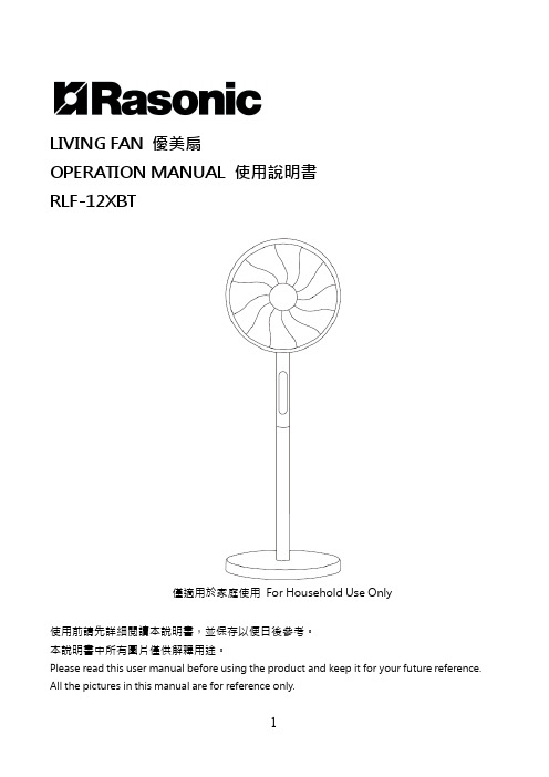
LIVING FAN 優美扇OPERATION MANUAL 使用說明書RLF-12XBT僅適用於家庭使用For Household Use Only使用前請先詳細閱讀本說明書,並保存以便日後參考。
本說明書中所有圖片僅供解釋用途。
Please read this user manual before using the product and keep it for your future reference. All the pictures in this manual are for reference only.安全注意事項(請務必詳細閱讀及遵守安全指導)1.請務必嚴格遵守以下說明之注意事項,以防止對使用者或其他人造成傷害或財物損失。
2.用戶必須使用有安全認證的合格插座,否則,可能會引起火災的危險。
3.此設備可供8歲以上兒童,肢體、感官、心智殘缺或缺乏經驗和知識的人使用,但他們必須已獲得監督和安全使用該設備的指導,並且了解其中的危害。
兒童不應將本產品用於玩耍。
不得讓兒童在沒有監督的情況下進行清潔和保養。
4.本設備是不打算供與(包括兒童)身體,感官或智力有障礙,或缺乏經驗和知識人士使用,除非他們是在負責他們安全的人員監督或有關使用該設備的指示下使用。
兒童應當受到監督以確保他們不會玩耍器具,請勿讓兒童爬上風扇。
5.拔掉電源線插頭時須緊握,切勿拉扯電線。
6.確保電源插頭完全插入插座,否則會引致觸電或接觸不良導致插頭過熱而釀成火災。
7.要定期清除電源插頭及插座上之灰塵,否則引致絕緣不良而導致火災。
8.若電源線有裸露或有損壞時,切勿使用本機。
避免危險,必須交由信興電器服務中心有限公司維修。
如果電源線損壞或產品出現故障,必須交由信興電器服務中心有限公司更換或維修,以避免危險。
切勿自行拆卸、檢修,或更換非生產商提供的配件。
9.切勿過度擰捏,彎曲或扭轉電源線,否則線芯可能會曝露在外或折斷,並引致觸電,短路,火災及產品損壞。
风扇冷气机单元用户手册说明书
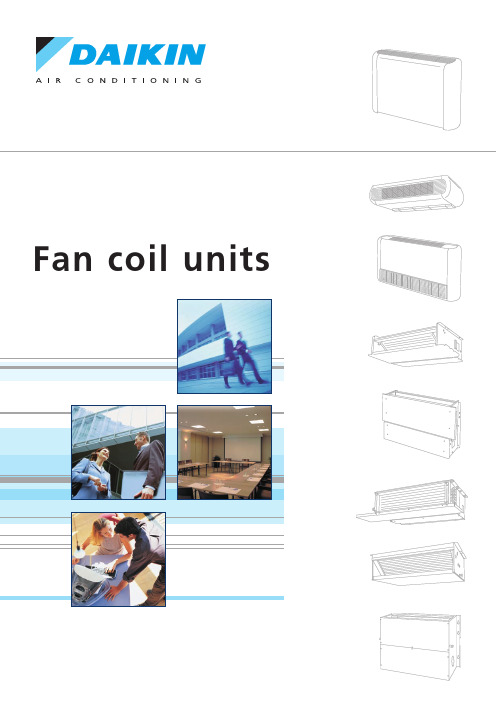
Fan coil units3PictogrammesManual cool/heat changeover.Automatic cool/heat changeover based on water temperature.Automatic cool/heat changeover based on air temperature.Control of the 3-way/4-port ON/OFF valve.The water valve shut-off once the desired temperature is reached.The controller controls the electric heater as integration or replacement of the hot water heating system.When the operating mode selector witch is turned on “electric heater”and the electric heater is turned on,the fan runs continuously at medium speed.The fan speed can be set at one of the 3speeds (low,medium or maximun)by turning the operation mode selector.The fan speed is switched automatically based on the difference between the temperature set on the thermostat and the room temperature.Optimised comfort cooling.When the fan coil has reached the desired setpoint,the fan will operate at medium speed and at regular intervals to ensure constant room temperature and lower sound.The controller prevents the fan coil unit from operating in one mode,if the required water temperature is not achieved to operate in the selected mode.The dead zone is a temperature interval close to the set temperature.When the air is warmer/cooler than the top/lower limit of the neutral zone,the cooling/heating mode is selected.FWV FWL FWM01234567891011kWFWD24681012141618202224kWFWB24681012141618202224kW2-pipe4-pipeProduct portfolioFan Coil Reference 2-pipe4-pipeCooling HeatingFan Coil Reference 2-pipe4-pipeDaikin fan coil units deliver quiet,reliable,controllable comfort of air conditioning without all the noise of other central systems.Fan coil units are a highly efficient means of turning a water chiller or hot water boiler into an efficient,quiet air conditioning system.The units are super quiet because the only moving part is the fan;making them ideal for use in offices,hotels and the home.The new range of fan coil units offers 5models,of which 3in flexible application.A wide range of accessories is available.For the ultimate in quiet,controllable air conditioning with all the comfort but none of the bulk or noise,the clear choice is Daikin.Fan Coil ReferenceEasy to installFast and easy field set up,ready for use!KEY HOLE SYSTEM/LEVELLING•quick fixing system for wall/ceiling mountingadvantage:no need to unscrew the nut•units just need to be perfectly leveledadvantage:no need to calculate the condensate drainageWATER CONNECTION•pre-assembled3-way/4-port ON/OFF valves are available•valve packages are insulated,no extra drain pan required•valve packages contain balancing valves and sensor pocket•valve packages can be factory-mounted and are leak tested•same valve package can be installed vertically and horizontally,on theright or on the left side of the unit without changeadvantage:easy to connect even when space is limitedCONDENSATE DRAINAGE•condensate drain pan features slopes to reduce water accumulation•supplied with flexible rubber hose pipe for easy connectionadvantage:eliminates the need to align drain pan outlet withcustomer pipingadvantage:no need for collar if pipe diameter is compatibleQUICK ELECTRICAL CONNECTIONS•fast-on connections for electrical options:no tools needed•controls are already factory-wired and testedadvantage:control panel no longer needs to be opened(external customer connections)•wiring diagram on the cover of the electrical boxEasy to maintainLow maintenance and high effeciency QUICK REMOVAL OF WASHABLE FILTER•no tools needed•same system on vertical and horizontal unitsadvantage:very fast filter removalELECTRIC HEATER RESETTING•no relay up to2kW capacityadvantage:even quieter operation•manual reset easily accessible•equipped with two overheat cut-out thermostats(manual&automatic reset)advantage:anticipates the upcoming standardsFAN MOTOR/CONTROL PANEL ACCESSIBILITY•4screws to access to the fan motor•fan board is removable without bringing the unit down•motor is life-lubricated and has a life span of40,000hours•control panel removable by a single screw•can be unfolded for a better component access•removable grilles•easy access to control valvesSTRUCTURE•modular concept•height of the units only240mm for all the sizes•cooling coil and fan module is made of:-galvanised sheet steel-internally insulated(with3mm close-cell polyurethane)•key-hole system for fast mounting•rubber anti-vibration damper to isolate the unit from supporting structure •straight duct connector is mounted to both suction and discharge side(width30mm)•a template is available in the carton box for easy connection to the ceiling HEAT EXCHANGER•3,4or6stage row cooling coil•standard left handed water connections+air-purge(water connections can easily be turned)•drain pan can to collect the condensate from:-heat exchanger-regulating valvesFAN MOTOR ASSEMBLY•1,2or3centrifugal fans with forward profile blades,dynamically andstatically balanced•7-speed electrical motors(with thermal protection on windings)•all7speeds pre-wired in the factory in the terminal block of the switch box•to reduce the requested installation space is the terminal block located onthe same side as the water connectionsAIR FILTER•located in the air inlet•removable from the bottom•made of acrylic fiber,filter class EU2STRUCTURE•possibility of installation both in horizontal and vertical position•reduced height280mm up to model10•the unit is made of:-galvanised sheet steel-insulated with noise-proof/anti-condensing material(self-extinguishing in Class1,with a thickness of10mm)•key-hole system for fast mounting•straight duct connector is mounted to discharge side(width30mm)HEAT EXCHANGER•1or2stage row cooling coil•standard left handed water connections+air-purge•system for collecting and discharging condensate setup either for ceiling or wall mountingFAN MOTOR ASSEMBLY•dual intake centrifugal fans made of aluminum,dynamically and statically balanced •3-speed electric motor,installed on vibration damping supports(with thermal protection on windings)AIR FILTER•air-intake module+Filter is standard delivered with each unit•removable filter from the bottom•made of acrylic fiber,filter class EU201020304050607080910121618FWV/L/M FWB ///FWD///••••••••••••••••••••••••••••••••••••••••••••••••••••••••••••••••ECFWMB633ECFWER6ECFWEB6EPIMSA6EPIA6/Easy to control !The new fan coil units can be operated by 3different controllers:•electronic control built-in (ECFWEB6)•electronic control remote (ECFWER6)•electromechanical control built-in (ECFWMB6)The electronic control consists of:•operating mode selector ,to turn the fan coil on and off,to choose the type of operating mode (automatic or at fixed speed)and to control the electric heating •cooling /heating selector•operational LEDs that indicates the current operation mode •thermostat to control the room temperature•free contacts for external enabling signal that may switch on or off the unit.•free contacts for centralized cool/heat changeover •water temperature probe •air temperature probeSeveral configurations are possible by changing dip switches.The electromechanical controller includes a fan speed selector (3speeds +stop)and manual cool/heat changeover.In case of the on/off valves,control can also be done through this controller.Power interface /master slave interfaceAn additional interface is required for units with a current greater than 1,12A.Master slave interface (EPIMSA6:4x3A)For remote control of up to 4fan coil units,an optional master/slave interface can be installed.Up to 3EPIMSA6can be connected in parallel (-->max.12fan coils).Power interface (EPIA6:1x16A)This is absolutely required for connection of ECFWER6to FWD12to18.It can be used as an alternative for EPIMSA6for all other fan coils.master slave interface is only needed in case of remote control of multiple fan coil unitsobigation to use master slave interface or power interface obligation to use power interfaceControl featuresBasic control functionsOptionsCooling/heating changeover2-p i p e4-p i p e**=T N (2-p i p e ,w i t h o u t v a l v e s ),T V (2-p i p e ,w i t h v a l v e s ),F N (4-p i p e ,w i t h o u t v a l v e s )*C a n b e o r d e r e d f a c t o r y m o u n t e d **f a c t o r y m o u n t e d o n r e q u e s t Measuring conditions (at nominal air flow and ESP):COOLING •air temperature entering the unit:27°C/19°C •water temperature entering the unit 7°C •water temperature rise 5KHEATING •room air temperature 20°C •for 2pipe units :water temperature entering 50°C -water flow rate same as for the cooling test •for 4pipe units :-water temperature entering 70°C -water temperature leaving 60°FWV/FWL/FWM01-10C**010203040608102-p i p e (**=T N o r T V )COOLING total capacity (H)kW 1.54 2.09 2.93 4.33 4.77 6.718.02sensible capacity (H)kW 1.20 1.51 2.11 3.15 3.65 4.91 5.96water flow l/h 2653595047458201,1541,343pressure drop kPa 13131112141219HEATINGheating capacity (H)kW 2.14 2.57 3.81 5.63 6.367.8310.03water flow l/h 2653595047458201,1541,343pressure drop kPa 9119910916Power input HW 3753569898182244Coil water volume l 0.50.71 1.4 1.4 2.1 2.1Air flow H/M/L m 3/h 319/233/178344/271/211442/341/241706/497/361785/605/4701,011/771/5701,393/1,022/642Sound power level H/M/LdBA 45/39/3350/44/3847/41/3352/43/3556/49/4361/54/4766/59/49Weight FWVkg 19202530314141FWLkg 20212732334444FWMkg 141519232332324-p i p e (**=F N )COOLINGtotal capacity (H)kW 1.46 1.90 2.87 4.33 4.67 6.647.88sensible capacity (H)kW 1.14 1.51 2.07 3.15 3.57 4.85 5.85water flow l/h 2513274947458031,1421,355pressure dropkPa 13131112141219cooling coil water volume l 0.50.71 1.4 1.4 2.1 2.1HEATINGheating capacity (H)kW 1.90 2.10 3.08 5.05 5.307.919.30water flowl/h 196182286396465694816pressure dropkPa 785101089heating coil water volumel 0.20.20.30.40.40.60.6Power input H W 3753569898182244Air flow H/M/L m 3/h 307/225/174327/261/205431/332/238690/490/356763/593/460998/765/5651,362/1,007/636Sound power level H/M/LdBA 45/39/3350/44/3847/41/3352/43/3556/49/4361/54/4766/59/49Weight FWVkg 20212632334444FWLkg 21222834354646FWMkg 151620252534342p i p e /4-p i p eWater connections inch 1/2”1/2”1/2”1/2”1/2”3/4”3/4”Max.absorbed currentW 0.170.240.250.440.430.80 1.12DimensionsFWV/FWLmm 564x774x226564x984x226564x1,194x226FWMmm 535x584x224535x794x224535x1,004x224Power supplyV/~/Hz230/1/50Option description 01020304060810FWV FWL FWM Additional single row heat exchanger*ESRH02A6ESRH03A6ESRH06A6ESRH10A6x x x Electric heater**EEH01A6EEH02A6EEH03A6EEH06A6EEH10A6x x x 2-pipe ON-OFF 3-way motor driven valve E2MV03A6E2MV06A6E2MV10A6x x x with complete mounting kit*4-pipe ON-OFF 3-way motor driven valve E4MV03A6E4MV06A6E4MV10A6x x x with complete mounting kit*(**)Fan stop thermostat**YFSTA6xx x (only for ECFWMB6)Air intake &discharge grille +EAIDF02A6EAIDF03A6EAIDF06A6EAIDF10A6--x front filter fixing kit for concealed models Supporting feetESFV06A6ESFV10A6x -x (=supporting brackets +covers)Supporting feet +grille ESFVG02A6ESFVG03A6ESFVG06A6ESFVG10A6x --Manual fresh air intake louver EFA02A6EFA03A6EFA06A6EFA10A6x x x Rear panel for vertically installed units ERPV02A6ERPV03A6ERPV06A6ERPV06A6x x -Controller -electromechanical built-in**ECFWMB6x x -Controller -electronic built-in +water probe**ECFWEB6x x -Controller -electronic remote +water probe ECFWER6x x x Power interface for connection of up to 4FCU EPIMSA6x x x to a single control panel Vertical drain pan EDPVA6x x x Horizontal drain panEDPHA6-xx10FWBMeasuring conditions (at nominal airflow and ESP):COOLING •air temperature entering the unit :27°C/19°C •water temperature entering the unit 7°C •leaving the unit 12°C HEATING •room air temperature 20°C •for 2pipe units :water temperature entering 70°C -water temperature leaving 60°CFWB02-10AT0203040506070809102-p i p e COOLING total capacity (H)kW 2.61 3.14 3.49 5.08 5.45 6.477.578.6710.34sensible capacity (H)kW 1.88 2.16 2.34 3.6 3.87 4.4 5.23 5.96 6.9water flow l/h 4485395988739361,1111,2991,4881,774pressure drop kPa 8141115814212126HEATINGheating capacity (H)kW 5.47 6.01 6.4710.3111.3912.2815.0516.8518.78water flow l/h 4805275679049991,0771,3191,4791,647pressure dropkPa 710812710161518Machine weight kg 232426313335434548Dimensions (HxWxD)mm 239X1,039X609239x1,389x609239x1,739x609A d d .H e a t e x c h a n g e rHEATINGheating capacity (H)kW 3.14 5.9912.8water flow l/h 2755261,123pressure dropkPa 3582-p i p e /4-p i p e Air flow rate m 3/h 4008001,200Power input (H)W 106192294Max.absorbed current A 0.510.94 1.28Available static pressure Pa 716559Sound power level (H)dBA586069Power supply230V/1~/50HzOption description 020304050607080910Additional heat exchanger EAH04A6EAH07A6EAH10A63-way valve add.h/e E2MV307A6E2MV310A62-way valve add.h/e E2MV207A6E2MV210A6Fan stop thermostat YFSTA6Power interfaces (*)--EPIA6Master slave interface (*)EPIMSA6Controller electronic -remoteECFWER6(*)In combination with ECFWER6,EPIMSA6or EPIA6must be installed for FWB08-10Measuring conditions (at nominal air flow and ESP):COOLING •air temperature entering the unit:27°C/19°C •water temperature entering the unit 7°C •leaving the unit 12°CHEATING •room air temperature 20°C •for 2pipe units :water temperature entering 50°C -water flow rate same as for the cooling test •for 4pipe units :water temperature entering 70°C -water temperature leaving 60°CFWDDaikin products are distributed by:The present publication is drawn up by way of information only and does not constitute an offer binding upon Daikin Europe N.V..Daikin Europe N.V.has compiled the content of this publication to the best of its knowledge.No express or implied warranty is given for the completeness,accuracy,reliability or fitness for particular purpose of its content and the products and services presented therein.Specifications are subject to change without prior notice.Daikin Europe N.V.explicitly rejects any liability for any direct or indirect damage,in the broadest sense,arising from or related to the use and/or interpretation of this publication.All content is copyrighted by Daikin Europe N.V.Daikin Europe N.V.is approved by LRQA for its Quality Management System in accordance with the ISO9001standard.ISO9001pertains to quality assurance regarding design,development,manufacturing as well as to services related to the product.ISO14001assures an effective environmental management system in order to help protect human health and the environment from the potential impact of our activities,products and services and to assist in maintaining and improving the quality of the environment.Daikin units comply with the European regulations that guarantee the safety of the product.Daikin Europe NV participates in the Eurovent Certification Programme for Air Conditioners (AC),Liquid Chilling Packages (LCP)and Fan Coil Units (FC);the certified data of certified models are listed in the Eurovent Directory.Daikin’s unique position as a manufacturer of air conditioning equipment,compressors and refrigerants has led to its close involvement in environmental issues.For several years Daikin has had the intention to become a leader in the provision of environmental friendly products.This challenge demands the eco design and development of a wide range of products and an energy management system;which involves energy conservation and reduction of waste.E P C E N 07-401/500/02/07/L a M o v i d a T h e p r e s e n t p u b l i c a t i o n s u p e r s e d e s E P L E 04-25B .P r i n t e d o n n o n -c h l o r i n a t e d p a p e r /P r i n t e d i n B e l g i u m C o p y r i g h t ©D a i k i nNaamloze Vennootschap Zandvoordestraat 300B-8400Ostend,Belgium www.daikin.eu BTW:BE 0412120336RPR Oostende。
bllc新风系统控制面板说明intermittent
bllc新风系统控制面板说明intermittentbllc新风系统控制面板说明控制面板操作:1、开关:顾名思义,开机和关机;2、模式:模式选择中,点击可切换暖风和冷风;3、风速:bllc新风系统控制面板说明风速一般分为高速、中速、低速、自动四个档位,制冷制热可根据个人需求进行调节,点击切换各档位;4、温度调节:温度调节为两个按钮,一个是加温,另一个是降温,bllc新风系统控制面板说明的设置为最高30℃,最低16℃。
5、bllc新风系统控制面板说明使用一般都有制冷和制热的功能,格力的使用上会有一个“模式”的按键,按下这个键之后,显示屏就会出现“雪花”的图案。
看到雪花图案之后,就可以松手了。
这已经是进入了制冷模式了。
在模式键的四周围,是有一些三角形的按键的,这些三角形的方向分别是上下左右。
如果想要温度上升,就按“上”,如果想要温度下降,就按“下”。
根据自己想要的温度进行调节;6、如果想要进行制热,这样操作:也是按下“模式”键,看到显示屏上“太阳”出现了就可以松手是,也是使用“上”“下”进行调节温度;7、想要设定除湿的话,和上面的操作方法一样,按住“模式”键,等出现了“水滴”图案就松手。
在“上”“下”这两个按键里进行调节;8、想要设置送风的话,和上面的步骤是一样的。
调节到自己想要的温度就可以了;9、bllc新风系统控制面板说明使用是有很多的图标的,“树叶”的图标是健康模式的,制冷不好,想取消的话按多一下“健康”就可以了。
“雪花”是制冷。
“太阳”是制热模式。
另外,还有一个“三角循环”的图标,这个而是循环风,而“风扇”是自然风,“水滴”就是除湿了。
采用有线温控器和无线遥控器对bllc新风系统控制面板说明进行控制。
主机温控器安装在室内主机下方的墙壁上,直接控制主机的开关。
温控器可以设定温度、定时,并选择运行模式(制冷、制热、除湿、送风、睡眠等);无线遥控器用来在5米左右的距离内遥控主机温控器,同样能达到控制主机的目的。
沃森新风系统面板说明
沃森新风系统面板说明
沃森新风系统面板通常包括以下功能说明:
1. 空气质量指示:显示当前室内空气的PM
2.5、TVOC、CO2等指标,用不同颜色的灯光来表示室内空气的状况。
2. 机组运行状态:显示新风机组的工作状态,包括主机状态、风机状态、送风状态、排风状态以及双通道状态等。
3. 定时开关机:可设置新风系统的定时开关机功能,按照预先设定的时间自动启停新风系统,保障室内空气质量。
4. 风速调节:可根据实际需要控制新风机组的送风风速和排风风速,以满足不同的使用场景。
5. 智能控制:支持通过手机或者智能家居中心控制新风系统的启停、风速、定时开关机等设置,方便用户随时掌控室内空气质量。
需要注意的是,在使用新风系统面板前,请确保已经仔细阅读说明书,并按照说明书中的操作步骤正确使用新风系统,以免产生不必要的损失。
天花板 墙壁通风机使用说明书
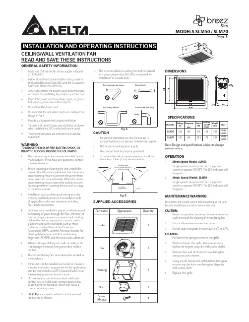
CEILING/WALL VENTILATION FANREAD AND SAVE THESE INSTRUCTIONSGENERAL SAFETY INFORMATION1.Make sure that the electric service supply voltage is AC 120V, 60Hz.2.Follow all local electrical and safety codes, as well as the Nation Electrical Code (NEC) and the Occupation Safety and Health Act (OSH Act).3.Always disconnect the power source before working on or near the ventilating fan, motor or junction box.4.Protect the power cord from sharp edges, oil, grease, hot surfaces, chemicals or other objects.5.Do not kink the power cord.6.Do not install the unit where ducts are con gured as shown in Fig. A.7.Provide suction parts with proper ventilation. 8.This unit is UL listed for use over a bathtub or shower when installed in a GFCI protected branch circuit. 9.These ventilating fans are intended for residential usage only.WARNINGTO REDUCE THE RISK OF FIRE, ELECTRIC SHOCK, OR INJURY TO PERSONS, OBSERVE THE FOLLOWING:CAUTION1.For general ventilating use only. Do not use toexhaust hazardous or explosive materials and vapors. 2.Not for use in cooking areas. (Fig. B)SUPPLIED ACCESSORIESFig. B1.Use this unit only in the manner intended by the manufacturer. If you have any questions, contact the manufacturer.2.3.Installation work and electrical wiring must be done by quali ed person(s) in accordance with all applicable codes and standards, including re -rated construction.4.5.When cutting or drilling into walls or ceiling s, do not damage electrical wiring and other hidden utilities.6. 7.Ducted ventilating fans must always be vented to the outdoors.8.If this unit is to be installed over a tub or shower, it must be marked as appropriate for the application and be connected to a GFCI (Ground Fault Circuit Interrupter) -protected branch circuit.3.4.This product must be properly groundedDIMENSIONSSPECIFICATIONSNote: Design and speci cations subject to change without notice.OPERATION1. Single Speed Model: SLM502. Single Speed Model: SLM70MAINTENANCE WARNING:Disconnect the power source before working on the unit. Routine maintenance must be done every year.CAUTION: 1. Never use gasoline, benzene, thinner or any othersuch chemicals for cleaning the ventilating fan. 2. Do not allow water to enter the motor.3.Do not soak resin parts in water over 60°C (140°F).CLEANING 1. Pull down the spring to remove the grille. 2.Wash and clean the grille. (Use non-abrasivekitchen de tergent, wipe dry with a new cloth.) 3.Remove dust and dirt from the ventilating fan using a vacuum cleaner.4.Using a cloth dampened with kitchen detergent, remove any dirt from ventilating fan. Wipe dry with a new cloth. 5.Replace the grille.Before servicing or cleaning the unit, switch the power o at the service panel and lock the service disconnecting means to prevent the power from being switched on accidentally. When the service disconnecting means cannot be locked, securely fasten a prominent warning device, such as a tag, to the service panel.Single speed control mode: Turn the powerswitch to operate ON/OFF. The LED indicator will be green.Single speed control mode: Turn the powerswitch to operate ON/OFF. The LED indicator will be green.To reduce the risk of injury to persons, install the fan at least 7 feet (2.1m) above the oor.Su cient air is needed for proper combustion and exhausting of gases through the ue (chimney) of fuel burning equipment to prevent back drafting. Follow the heating equipment manufacturer’s guideline and safety standards such as those published by the National Fire ProtectionAssociation (NFPA), and the American Society for Heating Refrigeration and Air ConditioningEngineers (ASHRAE) and the local code authorities.Do not use this unit with any other solid-state control device. Solid-state controls devices may cause harmonic distortion, which can cause a motor humming noise.10. Not to be installed in a ceiling thermally insulatedto a value greater than R50. (This is required for installation in Canada only).9.NEVER place a switch where it can be reached from a tub or shower.Proper insulation around the fan to minimize building heat loss and gain.INSTALLATIONS1. Remove the motor plate from the housing by removing the three screws. (Fig. C)2.Remove the wiring cover from the housing by pulling straight out. Choose a hole and use a slotted screwdriver to remove it. (Fig. D) 3.Follow all local electrical and safety codes. NEVERplace a switch where it can be reached from a tub or shower. Connect wires as shown in wiring diagrams. (Fig. E)4.Using wire nuts , connect the house power cableto the ventilating fan wires. 14 AWG (2.1 mm 2) isthe smallest conductor that shall be used forbranch-circuit wiring. (Fig. F)5.Insert the duct into the duct connector and tape all ductwork connection s to make them secure and air tight. Install the duct with a gradient 1°~2° to the outside. (Fig. G)6.New installation prior to nishing the ceiling or wall: Insert the fan between joists. Make sure the fan body is level and p erpendicular with the joist. (Fig. H)7.Replacement installation: After makingelectrical and ductwork connections (see steps 2~5),nail the housing in place. Drive nails through the housing w here indicated by arrows. (Fig. I)8.New installation in an existing ceiling or wall:Bend tabs outward 90°(Use a screw driver if desired) and position housing so that tabs rest againstthe bottom edge of the joists (or front of stud). Nail the housing to the joist or stud using four nails to ensure a solid, quiet installation. Ceiling installations: Tabs on the opposite side of the housing can be bent outward to rest on top of 1/2" ceiling material and provide extra stability.(Fig. J)9. Plug in themotor a nd lock the fan body back by using three screws. (Fig. C)10.Squeeze the grille springs together and insert the springs into the slots i n the motor plate. Push the grille up against the ceiling or wall.When the power is on, check for abnormal vibrations or sounds. Insert the mounting springs into the slots and mount the grille to the body.(Fig. K)WARRANTYDELTA ELECTRONICS THREE YEARSLIMITTED WARRANTY Delta Electronics Inc. (“Delta Electronics”) warrants to the original consumer purchaser in the USA and Canada that the Breez ventilation fan products will be free from defects in material or workmanship. This warranty is limited to three (3) years from the original date of purchase.Limitations and ExclusionsDuring the warranty period, a replacement for any defective product will be supplied free of charge for installation by the consumer. The warranty provided herein does not cover charges for labor or other costs incurred in the troubleshooting, repair, removal, and installation service.All returns of defective parts or products must include the product model number, and must be made through an authorized Delta Electronics distributor. Authorized returns must be shipped prepaid. Repaired or replacement products will be shipped by Delta Electronics F.O.B. shipping point.Delta Electronics shall not be liable for any indirect, incidental, consequential, punitive, or special damages arising out of or in connection with products use or performance, regardless of the form of actionwhether in contract, tort (including negligence), strict product liability or otherwise.This warranty does not extend to uorescent lamp starters and tubes.The warranty does not cover if user does not comply with manufacture’s installation manual.To qualify for warranty service, you must notify Delta Electronics at the address or telephone number below.Delta Electronics shall have no liability to the original owner-user with respect to any defect caused by abuse, misuse, neglect, improper transportation or storage, improper testing, improper installation, improper operation, improper use, improper maintenance, improper repair, improper alteration, improper modi cation, tampering or accident of products or parts thereof, or unusual deterioration or degradation ofproducts or parts thereof due to a physical environment beyond the requirements of products’ speci cations.Address: 46101 Fremont Boulevard, Fremont, CA 94538 US Toll Free Number: 1-888-979-9889。
新风系统功能说明书终版(20151220)

赛菲新风机功能说明书(此说明书要适用无空调款机型)一、整机特性1、输入特性:输入端子L,N和接交流市电,为三个单插片6.3*0.8;系统工作电压为185V-240V/AC 。
2、性能指标1.控制器采用液晶显示2.控制板工作环境及储存要求:①工作温度:-20℃~85℃(室内机);②相对湿度:30~95RH?;③储存温度:-30℃~90;3.工作电压范围:185V-240V/AC;4.温度控制范围及控制精度:16℃~30℃?0.5℃,温度回差?1℃;5.温度显示范围:-30℃~90℃;6. 整机待机功率消耗:<2W;7. 电气控制部分要有良好的电磁兼容性能;8. 安全性能:符合GB4706.1-2005和GB4706.32-2005标准。
2、整机组成显示板GSC0040B电源控制板 GSC0040A变频板GSC0040CWIFI模块板GSC0040D液晶模组LCD-315A(黑底白字)粉尘传感器 PMS1003(客供)二氧化碳传感器 T6603客供温度传感器 4路(分别为新风入风口、排风入风口,新风出风口、室外排风出口)风机1 变频交流风机风机2 变频交流风机压缩机客供四通阀客供3、信号采集粉尘传感器 PMS1003(客供)(赛纳威备选数显)二氧化碳传感器T6603温度传感器 4路(分别为新风入风口、排风入风口,新风出风口、室外排风出口)二、净化机控制系统按键说明1、按键控制说明整机共有5个触摸按键,包含1个开关按键和4个功能键。
电源开关需用一个(橙蓝)双色发光二极管做出两种状态指示,其他按键由一个白色微蓝发光二极管做出状态指示。
所有正常按键操作都有提示音一声,提示操作有效(提示声音要选用美音或者由客户指定)。
2、开关键“”开关键的作用是切换控制板开机运行与待机状态。
机器通电后处于待机状态,屏幕和其他按键状态指示灯不亮,只有开关键亮橙色灯,指示整机现在处于待机状态,此时除开关键外其他按键均无效。
一旦按下开机键“”,音效提醒操作有效,开关键周围亮蓝色灯,控制板开机运行,此时所有按键指示灯和屏幕图标全亮3秒,然后按照实际运行功能键和图标亮灯,整机按默认的运行模式运行:风机风量为低风启动(默认上次风量)、PM2.5传感器、CO2传感器及各自检功能开启。
新风系统操作说明

新风系统操作说明
本系统为恒温控制系统,控制对象:水阀开度、变频器输出控制、风机启停、新风阀等。
控制原理:水阀:空调机组系统送电,PLC 正常运行,根据温度传感器检测的信号,在控制器内与温度设定值比较,输出信号控制水阀开度,以维持房间温度的恒定。
夏季模式时,当温度采样值高于设定值时,冷水阀开大;当温度采样低于设定值时,冷水阀关小;冬季模式时,当温度采样值高于设定值时,热水阀关小;当温度采样低于设定值时,热水阀开大。
新风阀:空调机组系统送电,PLC 正常运行,根据温度传感器检测的信号,在控制器内与温度设定值比较,输出信号控制新阀开度,以维持房间温度的恒定。
夏季模式时,当室外温度值高于室内温度时,新风阀关闭;当室外温度采样低于室内温度时,新风阀打开;冬季模式时,当室外温度采样值高于室内温度值时,新风阀开大;当室外温度采样低于室内温度时,新风阀关闭。
当夏季模式时,根据室外温度,开启新风阀,当新风阀开启后,水阀根据新风阀开度大小,延时开启水阀,初始值为:30Min 室外空气实际温湿度 空调箱名称
冬夏季模式
当前报警显示
回风实际温度 新风阀最小开度
电动阀开度控制
新风阀开度控制
变频器频率显示 当室外温度与需求温度设定值超过此温度。
kf500a新风控制面板说明书
kf500a新风控制面板说明书KF500A新风控制面板说明书一、产品介绍KF500A新风控制面板是一款用于控制新风系统的智能设备。
它采用先进的技术和设计,为用户提供便捷、舒适的室内环境。
本控制面板具有多种功能,包括温度调节、湿度调节、定时开关、风速调节等,可满足用户对新风系统的各种需求。
二、外观与安装KF500A新风控制面板外观简洁美观,采用高质量的材料制作而成。
面板尺寸适中,易于安装在墙壁上。
安装时需注意面板与墙面的垂直度,以保证整体效果美观。
三、功能说明1. 温度调节:KF500A新风控制面板可根据室内温度自动调节新风系统的运行状态,保持室内温度舒适宜人。
用户可根据自身需求设置温度范围,控制面板将根据设定的温度进行自动调节。
2. 湿度调节:KF500A新风控制面板还具备湿度调节功能,可根据室内湿度自动调节新风系统的湿度输出。
用户可根据需要设置湿度范围,控制面板将根据设定的湿度进行自动调节,保持室内湿度在舒适范围内。
3. 定时开关:KF500A新风控制面板具备定时开关功能,用户可根据需要设置新风系统的开启和关闭时间。
通过合理设置定时开关,可以在用户离开或睡眠时关闭新风系统,节省能源同时保证室内空气质量。
4. 风速调节:KF500A新风控制面板支持多档风速调节,用户可根据需求选择合适的风速档位。
高档位可快速通风,低档位可保持室内空气流动,满足不同季节和使用场景下的需求。
5. 智能模式:KF500A新风控制面板还具备智能模式功能,用户可选择智能模式后,控制面板将根据室内环境自动调节新风系统的运行状态,保持室内空气质量在较好状态。
四、操作说明1. 开关机:KF500A新风控制面板的开关机按钮位于面板顶部,用户可通过按下该按钮实现开关机操作。
2. 温度调节:KF500A新风控制面板的温度调节按钮位于面板正中央,用户可通过按钮上下调节温度。
3. 湿度调节:KF500A新风控制面板的湿度调节按钮位于面板右侧,用户可通过按钮上下调节湿度。
新风操作手册.

7)送风温度:设定值后程序自动控制将送风温度稳定在设定值范围内;
8)芯体温度:换热机型,防止芯体结冰,左侧为上限,右侧为下限,芯体温度到达下限,关闭新风机及风阀,达到上限时再开启新风机和风阀;
例如:修改“日期”:按上键或下键选择如图2-9所示。
图2-9
按“确认”键进入时间修改,如图2-10所示。
图2-10
按“上/下”键修改数据如图2-11所示。
图2-11
按“确认”键数据保存。
3)密码设置
用来设定空调控制面板的密码,选择密码设置后,按下“确认”键,如图2-12所示。
图2-12
用“上/下”键来设置密码。
例如:修改“室内温度”,按“上/下”选择“室内温度பைடு நூலகம்如图2-3所示。
按“确认”键进入设定修改
图片8
按“上/下”键修改数据
图2-3
按“确认”键将数据保存,其他各参数设定方法以此类推。
2.2报警设置
选择报警设置选项,按下“确认”键,如图2-4所示。
图2-4
选择“当前报警”项,按“确认”键,可以显示当前报警原因
▪2 节能空调季节性开启原则
节能空调设计的基本理念和出发点是应用于通讯机房节能降耗,实现功能是替代和部分替代机房空调制冷,节能原理是充分利用自然冷源维持机房环境,实现有效节能,所谓有效节能指的便是节能空调季节性应用的基本原则。
FCX-075B型节能空调,别名为新风降温节能空调,原理是过滤引入室外新风,再经湿帘加湿实现二次过滤降温处理,而后由主风机送入机房,很明显东北地区夏季高温天气时,室外新风的温度比机房内的温度还要高得多,这样的空气经过湿帘后变成湿热空气,并不能达到节能的目的,所以夏季(6月,7月,8月),建议性不用新风节能空调,而春秋季节(3,4,5,9,10,11月)节能效果非常明显,是新风降温节能空调的最佳季节,冬季(12,1,2月)天气比较寒冷,这个季节建议在气温为-30℃以上时应用新风降温节能空调,这样就可以达到机房安全稳定的节能。
北极星牌全自动高级豪华风扇说明书
北极星牌全自动高级豪华风扇说明书
关于安装:先锋空调扇一般都不需要安装,部分产品需要自己安装脚轮,脚轮安装也比较方便,直接把脚轮上面的金属杆插入底部脚轮安装口即可。
使用方法:一开始加水到水箱中,使水位在最高值(加满后一般可用8至10小时),然后启动加湿键,以便水能够循环。
注意:空调扇开启后再按加湿键,吹干去背后的冰帘,以增加使用期限。
先锋遥控板系列产品拥有延时风干的功能,关掉后需等待几分钟再切断电源。
冰晶的使用:每台产品一般都有两个冰晶,在冰箱中冷冻2小时,然后放在水箱中,起到降温的作用,使得空调扇吹出凉风。
冰晶有充兑好的和干的之分,后者需要加水到最高值,拧紧再使用。
清洗方法:初次使用应先将水箱洗净,同时将后部的冰帘冲洗干净。
在使用期间,需要经常清洁水箱,以免将水泵堵牢引发故障。
- 1、下载文档前请自行甄别文档内容的完整性,平台不提供额外的编辑、内容补充、找答案等附加服务。
- 2、"仅部分预览"的文档,不可在线预览部分如存在完整性等问题,可反馈申请退款(可完整预览的文档不适用该条件!)。
- 3、如文档侵犯您的权益,请联系客服反馈,我们会尽快为您处理(人工客服工作时间:9:00-18:30)。
griwind新风系统面板说明书
Griwind新风系统面板说明书
一、产品概述
Griwind新风系统面板是一种用于控制新风系统运行的设备。
新风系统是一种能够将室外新鲜空气通过过滤和调节后送入室内的系统,可以改善室内空气质量,提供舒适的室内环境。
二、外观和结构
1. 外观:Griwind新风系统面板采用简约而精致的设计,外观整洁、美观。
2. 结构:面板由高质量的材料制成,具有良好的耐久性和防护性能。
面板上配备了多个按键和显示屏,方便用户对新风系统进行操作和监控。
三、功能和特点
1. 控制功能:面板上的按键和显示屏可以实现对新风系统的启停、风速调节、温度控制等操作。
2. 显示功能:面板上的显示屏可以显示当前的室内温度、湿度、风速等参数,帮助用户了解室内环境状况。
3. 定时功能:面板支持定时启停功能,用户可以根据需要设置新风系统的工作时间,提高能源利用效率。
4. 过滤功能:面板上的过滤器指示灯可以提醒用户更换过滤器,确
保新风系统的正常运行和室内空气的质量。
5. 报警功能:面板具备故障报警功能,当新风系统出现故障时,面板会发出声光报警提示,提醒用户及时处理问题。
四、安装和使用
1. 安装:请将Griwind新风系统面板安装在室内便于操作的位置,确保与新风系统的连接正确可靠。
2. 电源连接:将面板的电源线与交流电源连接,确保电源供应稳定。
3. 操作指南:按照说明书上的操作指南,正确使用面板上的按键进行相应的操作,如启停、风速调节、温度控制等。
4. 监控参数:通过面板上的显示屏,实时监控室内温度、湿度、风速等参数,根据需要调整新风系统的工作状态。
五、注意事项
1. 请勿在湿度较高的环境中使用面板,以免影响其正常运行和寿命。
2. 面板应远离火源、水源等可能引起损坏或危险的物体。
3. 请勿私自拆卸或更换面板内部零部件,以免引起故障或安全隐患。
4. 面板应避免受到强烈的撞击或挤压,以免损坏外壳和内部电路。
5. 请定期清洁面板外壳,保持其外观整洁和使用寿命。
6. 面板故障时,请及时联系专业人员进行维修或更换。
六、常见问题解答
1. 问:面板上的显示屏无法正常显示?
答:请检查面板的电源连接是否稳定,若连接正常但问题仍未解决,请联系售后服务。
2. 问:面板无法启动新风系统?
答:请检查面板与新风系统的连接是否正确,确保电源供应稳定,若问题仍存在,请联系售后服务。
3. 问:面板上的按键无法正常操作?
答:请检查面板是否受到损坏或水浸,若问题仍未解决,请联系售后服务。
七、售后服务
如有任何问题或需求,请联系我们的售后服务部门,我们将竭诚为您提供解答和支持。
八、总结
Griwind新风系统面板是一种功能齐全、易于操作的设备,能够提供舒适的室内环境和高质量的新鲜空气。
通过仔细阅读本说明书并正确使用面板,您将能够充分发挥新风系统的功能,享受更健康和舒适的生活。
如有任何疑问或需求,请随时联系我们的售后服务部门。
