超声波传感器URM37 V4.0使用说明
超声波传感器使用说明
超声波传感器使用说明1.电源接入:将超声波传感器的电源线与电源连接,确保电压稳定。
2.连接触发引脚和接收引脚:超声波传感器有一个触发引脚和一个接收引脚,触发引脚用于发送超声波脉冲,接收引脚用于接收反射波。
将传感器的触发引脚与控制器的IO口相连,接收引脚与控制器的IO口相连。
3.发射超声波脉冲:在控制器上设置触发引脚为高电平,保持一段时间后再下降到低电平。
高电平触发传感器发射超声波脉冲,可以通过设置触发时间来控制脉冲的持续时间,一般来说,脉冲持续时间越长,测量距离的精度越高。
4.接收反射波信号:超声波传感器发射的脉冲波会在物体上反射并返回,传感器接收到这个反射波信号后,触发引脚会发出一个低电平信号。
通过测量这个低电平信号的持续时间,可以计算出目标物体与传感器之间的距离。
一般可以通过控制器的计时器功能来测量这个时间。
5.计算距离:利用传感器发送和接收的时间差,结合超声波在空气中的传播速度,可以精确计算出目标物体与传感器之间的距离。
一般计算公式为:距离=时间差×速度,其中速度一般取340m/s。
6.转换为实际距离:有些超声波传感器会输出一个毫秒级的时间差值,需要根据传感器的数据手册来进行换算,将时间差转换为实际距离。
需要注意的是,超声波传感器对目标物体的性质有一定要求,例如传感器对于反射率较低的物体,如软质材料、液体、吸声材料等,测量距离的精度可能会降低。
此外,超声波传感器也有一定的应用注意事项,比如需要避免在多传感器密集布置的环境下使用,避免互相的干扰;要避免在含有较多尘埃、雾霾等粒子的环境中使用,以免影响测量结果;还要避免在强电磁辐射的环境下使用,以防止电磁辐射对传感器的工作性能产生干扰。
总结起来,超声波传感器的使用非常简单,只需连接电源、触发引脚和接收引脚、发送超声波脉冲,然后通过计算时间差来获取目标物体与传感器之间的距离。
在应用中,还要注意目标物体的特性和环境的影响,以获取准确的测量结果。
超声波传感器详解PPT课件
振荡器产生的高频电压通过耦合电容CP供给超声波振子MA40S2S。CC4049的
H1和H2产生与超声波频率相对应的高频电压信号, H3~H6进行功率放大,再
经过耦合电容CP
MA40S2S。超声波振子若长时间加直流电
压,会使传感器特性明显变差, 因此,一般用交流电压通过耦合电容CP 供
b超声波在空气中传播2a2a19第7章超声波传感器20液位测量储油罐分选第7章超声波传感器21超声波液位计第7章超声波传感器22mdarse型室外保安机器人多个超声波传感器组成线阵或面阵形成多传感器第7章超声波传感器23为计数或安全目的进行人员探测第7章超声波传感器24堆置高度控制厚度测量第7章超声波传感器25脉冲回波法检测厚度工作原理超声波测厚第7章超声波传感器图910超声波测厚1双晶直探头2引线电缆3入射波4反射波5试件6测厚显示器图是超声波测厚示意图
α——衰减系数,单位为Np/cm(奈培/厘米)。
声波衰减原因: 扩散衰减:随声波传播距离增加而引起声能的减弱。 散射衰减:超声波在介质中传播时,固体介质中颗粒界面或流体介质中悬浮
粒子使声波产生散射,一部分声能不再沿原来传播方向运动,而 形成散射。 吸收衰减:由于介质粘滞性,使超声波在介质中传播时造成质点间的内摩 擦,从而使一部分声能转换为热能,通过热传导进行热交换,导 致声能的损耗。
第7章 超声波传感器
超声波液位计
第20页/共40页
第7章 超声波传感器 多个超声波传感器组成线阵或面阵形成多传感器
MDARS-E型室外保安机器人
第21页/共40页
第7章 超声波传感器
为计数或安全目的,进行人员探测
第22页/共40页
第7章 超声波传感器 堆置高度控制
Arduino控制URM37V3.2超声波测距传感器
下面是使用传感器的 PWM 输出读取距离数据,首先需要设置超声波的工作模式,根据手册我们可以看到需要设置为第三 工作模式。这里需要用到 RS232 转 TTL 模块或 USB 转 TTL 模块,如果你有 Arduino 也行(当然一定是控制芯片是直插式 的才行)。
我们就用 Arduino 来代替 USB 转 TTL 模块,来配置超声波传感器,具体做法如下:
void setup() { Serial.begin(9600); pinMode(ledpin,OUTPUT); digitalWrite(ledpin,LOW); delay(200);
}
void loop() {
flag=true; for(int i=0;i<4;i++) {
Serial.print(DMcmd[i],BYTE);//发送超声波测距命令 }
delay(75); //一个延时
while(flag)
{ if(Serial.available()>0) //查询串口有无数据 { int header=Serial.read(); //0x22 开始接收距离数据 int highbyte=Serial.read();//距离数据高 8 位 int lowbyte=Serial.read();//距离数据低 8 位 int sum=Serial.read();//sum 校验和
//
dela=true;
for(int i=0;i<4;i++)//温度命令发送 {
Serial.print(DMcmd[i],BYTE); }
delay(50); //延时 50 ms
while(flag) {
if(Serial.available()>0)//判断串口有无返回数据 {
超声波传感器产品说明说明书

ApplicationThe sensor measures the spectral absorption of process liquids in the ultraviolet region of the electromagnetic spectrum.•Measurement of protein concentrations •Chromatography monitoring •Filtration monitoring •Concentration measurement of organic compounds •Detection of aromatesYour benefits•Improved process control and easier quality control thanks to quick and reliable monitoring of product concentration –Measuring range up to 2.5 AU or 50 OD (depending on optical path length)–Measurement of UV absorption at discrete wavelengths between 254 nm and 313 nm –Outstanding filter properties for highest linearity –Direct concurrence with laboratory values –Integrated reference detector for lamp compensation –Gas discharge lamp for long service life and stable measured values •FM- and ATEX-approved lamps for applications in the hazardous area •Compliance with life sciences sector thanks to hygienic design and FDA- and USP-compliant sealing materials •High degree of product safety as SIP/CIP-resistant •High product yield thanks to low volume requirements •Maximum durability in all applications owing to wide range of materials and process connections •Can be adapted to process requirements:Optional air purge ports to prevent the formation of condensate on the optical windowsProducts Solutions ServicesTechnical Information OUSAF46Optical sensor with the OUA260 flow assembly for the measurement of UV absorptionTI01190C/07/EN/02.1771388454OUSAF462Endress+HauserFunction and system designMeasuring principle Light absorption The measuring principle is based on the Lambert-Beer law.There is a linear dependency between the absorption of light and the concentration of the absorbing substance:A = -log(T) = ε . c . OPL T = I/I 0T ... Transmission I ... Intensity of received light at detector I 0 ... Intensity of transmitted light of light source A ... Absorption ε ... Extinction coefficient c ... Concentration OPL ... Optical path lengthA light source emits radiation through the medium and the incident radiation is measured on the detector side.The subsequent conversion to absorbance units (AU, OD) is performed in the associated transmitter.1Absorption measurement with reference 1Light source 2Optical windows 3Measurement filter 4Measuring detector 5Lens 6Medium flow 7Reference filter 8Reference detectorOUSAF46 has 2 pairs of reference and measuring detectors (= 2 channels). Only one channel is shown for the sake of simplicity.Measuring system An optical measuring system comprises:•Sensor (photometer) OUSAF46•Transmitter, for example Liquiline CM44P •Cable set, for example CUK80•Assembly OUA260OUSAF46Endress+Hauser 32Example of a measuring system with a photometer sensor 1pipe 5Flow assembly OUA2602Transmitter CM44P 6Sensor: light source (lamp)3CUK80 cable set 7CUK80 cable set 4Sensor: detector InputMeasured variableUV-absorption Measuring range •0 to 2.5 AU •Max. 50 OD (depending on the optical path length)WavelengthDiscrete wavelength at 254, 280, 295 or 313 nm Power supplyElectrical connection The sensor is connected to the transmitter using the pre-terminated or labeled cable set CUK80 (for connection to CM44P) or OUK (for connection to CVM40) . The terminals and labeling may vary depending on the transmitter in use. The cable set must be ordered separately.OUSAF464Endress+Hauser3OUSAF46 connecting cable ALight source (lamp) power supply B Signals of measurement and reference detectorCable lengthMaximum 100 m (330 ft)Lamp voltage Versions for use inhazardous areas 1)Safety instructions for electrical apparatus in explosion-hazardous areas, XA01403CConnecting the detector using a safety barrierThe photometer sensors use silicon photovoltaic cells as detectors which are operated in the current mode. The detectors are intrinsically safe and can be deployed in Zone 1 and Class I, Division 1environments.1)Applies only to measuring points consisting of a photometer, CUK80 cable set and Liquiline CM44P transmitter.OUSAF46Endress+Hauser 5The safe area is separated from the hazardous area by safety barrier MTL7760AC.4Safety barrier, dimensions in mm (inch)The safety barrier may only have a very low leak current since the optical signals from the sensor can be in the nanoampere range. Therefore, the sensor cable shield is connected to the ground terminal of the barrier.On delivery, the CUK80 detector cable is permanently wired to the . All you have to do is simply connect the individual cable ends to the detector and transmitter.Connecting the hazardous area lamp using a junction boxThe hazardous area lamp (EXP-1) must be connected to the transmitter using a certified junction box.For versions with FM approval, the junction box is included in the delivery and already pre-terminated on the lamp side. You simply have to connect the cable of the transmitter (CUK80)to the terminals of the junction box.For versions with ATEX approval, the junction box is not included in the delivery and it and the cable glands required must be provided by the customer at the place of installation. You must connect the cables entirely on your own (CUK80 of transmitter and lamp cable of photometer sensor).OUSAF466Endress+HauserInstallation5Mounting angles. The arrows indicate the direction of medium flow in the pipe.ASuitable mounting angle, better than C BOptimum mounting angle, best installation position CAcceptable mounting angle DMounting angle to be avoided E Forbidden mounting angleEnvironmentAmbient temperature0 to 55 °C (32 to 130 °F)Storage temperature-10 to +70 °C (+10 to +160 °F)Humidity5 to 95 %Degree of protection IP 65 (NEMA 4) for all optical partsProcessProcess temperature 0 to 90 °C (32 to 194 °F) continuousMax. 130 °C (266 °F) for 2 hoursProcess pressure Max. 100 bar (1450 psi) absolute, depending on the material, pipe size and process connection of the flow assemblyOUSAF46Endress+Hauser 7Mechanical construction6Sensor module ADimension of lamp → Table BDimension of detector → Table C Assembly, see Technical Information for assembly The total length of the sensor module is derived from the lengths of the lamp, the detector and the assembly.The dimensions of the OUA260 assembly are provided in Technical Information, TI00418C.‣Allow an additional gap of 5 cm (2") on both the lamp side and detector side of the sensor to connect the sensor cable.Weight SensorUV lamp0.58 kg (1.28 lbs)UV lamp with wire-braided cable (1.2 m (4 ft)) and junction box (sensor for hazardous area)3.2 kg (6.66 lbs)Easycal detector0.53 kg (1.17 lbs)Standard detector0.78 kg (1.71 lbs)Materials Sensor housingStainless steel 316Assembly OUA260Stainless steel 316, 316L or Kynar Cable connector endsNickel-plated brass Light sourceLow-pressure mercury lampLamp operating life: typically 3000 hDetectorUV silicon detector, hermetically sealed Filter Multilayer interference filter, designed for extreme UV conditionsOUSAF468Endress+HauserCertificates and approvalsmark Declaration of ConformityThe product meets the requirements of the harmonized European standards. As such, it complies with the legal specifications of the EU directives. The manufacturer confirms successful testing of the product by affixing to it the mark.Ex approvals •ATEX II 2G Ex db IIC T5 Gb •FM Cl.1, Div. 1, Groups B, C, DFDA conformityAll non-metal parts in contact with medium, such as rubber and plastic parts, meet the requirements of FDA 21 CFR 177.2600. The plastic and elastomer parts of the sensor in contact with medium have passed the biological reactivity tests according to USP <87> and <88> Class VI.Ordering informationProduct page /ousaf46Product Configurator On the product page there is a "Configure" button to the right of the product image Configure .1.Click this button. The Configurator opens in a separate window.2.Select all the options to configure the device in line with your requirements. In this way, you receive a valid and complete order code for the device.3.Export the order code as a PDF or Excel file. To do so, click the appropriate button on the rightabove the selection window.For many products you also have the option of downloading CAD or 2D drawings of the selected product version. Click the tab for this CAD and select the desired file type using picklists.Scope of delivery The scope of delivery consists of the following :•Detector and lamp module without flow assembly or •Detector and lamp module mounted on flow assembly •Operating InstructionsOrdering the sensor together with a transmitter:If you select the calibration option in the Product Configurator for the transmitter , the complete measuring system (transmitter, sensor, cable) is factory-calibrated and shipped as one package.‣If you have any queries:Please contact your supplier or local sales center.AccessoriesThe following are the most important accessories available at the time this documentation was issued.‣For accessories not listed here, please contact your Service or Sales Center.OUSAF46Endress+Hauser 9Flow assembly OUA260•Flow assembly for hygienic sensors •For sensor installation in pipes •Materials: stainless steel 316, 316L or Kynar (other materials available on request)•Wide variety of process connections and path lengths available •Product Configurator on the product page:/oua260Technical Information TI00418CCable CUK80 cable set •Pre-terminated and labeled cables for connecting analog photometer sensors •Product Configurator on the product page: /cuk80CalibrationKit OUSAF46 EasyCal retrofit kit •Patented system traceable to NIST for the calibration of UV absorption sensors •Order numbers:–254 nm: 71210149–280 nm: 71210150–295 nm: 71210156–313 nm: 71210151Reference rod Order number: 71108543。
邦纳 超声波传感器操作说明
示教成功: 电源灯: 亮绿灯 示教不成功: 相应输出灯: 继续黄灯闪烁
PDF 文件使用 "pdfFactory Pro" 试用版本创建
T30U双开关量操作
OUTPUT2在设定检测窗口输出,在设定窗口之外时 OUTPUT1互补输出.
按键示教方法
同时按住两个按纽并 保持2S以上
作用 当传感器在正常工作状态下目标物超过设定范围(常开模式) 当传感器在正常工作状态下目标物在设定范围内(常开模式) 等待示教第一点(示教模式) 等待示教每二点(示教模式)
PDF 文件使用 "pdfFactory Pro" 试用版本创建
QS18U操作
两点示教方法
传感器就在您设定的两点范围之内进行输出
远程示教 给示教线四个正脉冲
结果 锁定/解锁相互转换
PDF 文件使用 "pdfFactory Pro" 试用版本创建
T30U开关量与模拟量操作
电源灯 不亮 绿灯闪烁 亮绿色
没有电源 输出过载 传感器正常工作状态
作用
信号灯
作用
不亮
表示声波没有返回来
红灯闪烁
表示传感器接受信号的强弱,闪烁越快,信号越强.
接线图
PDF 文件使用 "pdfFactory Pro" 试用版本创建
S18U操作
电源灯/信号灯
输出灯/示教灯 按键
电源灯/信号灯 不亮 亮红色 亮绿色
作用 没有电源 传感器没有接收到回波 传感器正常工作状态,并且信号很好.
输出/示教灯 不亮 亮黄灯 亮红灯 红灯闪烁
将目标物放在第一点 位置 按一下按纽
将目标物放在第二点 的位置 再按一下按纽
211230370_一种高效的汽车摄像头智能清洗装置
向载荷基本不变,提高结构的防撞安全性。
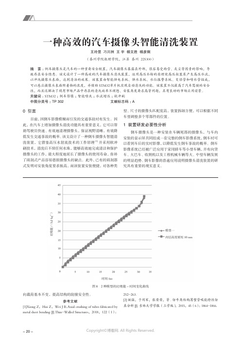
参考文献[1]Xiong Z,Hui Z,Wei J R.Axial crushing of tubes fabricated by metal sheet bending [J].Thin-Walled Structures,2018,122(1):252-263.[2]皱猛,于用军,张荣荣,等.仿牛角结构薄壁管吸能特性仿真分析[J].吉林大学学报(工学版),2015,45(6):1864-1866.时间/ms比吸能/(k J ·k g -1)模型一内层高度缩短10 mm图8 2种模型的比吸能-时间变化曲线4540353025201510551015202530350 引言目前,因倒车影像模糊而引发的交通事故时有发生。
因此,在汽车上增加摄像头清洗功能具有重要意义,它可以帮助驾驶员快速、有效地清理摄像头,保证视野清晰,有效降低发生交通事故的概率。
该文设计了一种倒车摄像头智能清洗装置,它借鉴高压水射流技术的工作原理[1]并采用软冲刷技术,清洗后不留任何水珠,能够高效地完成清洁和保护摄像头的工作,最大程度地延长了摄像头的使用寿命,弥补了雨刮式产品容易磨损摄像头的缺点。
此外,已有的雨刮器式发明对安装角度要求极高,而该装置安装便捷,对各种类型、尺寸的摄像头匹配度高,装置拆卸方便,可以根据不同车型调整多个零部件的位置。
1 装置研发必要性分析倒车摄像头是一种安装在车辆尾部的摄像头,与车内安装的显示屏共同组成一套完整的倒车影像系统,倒车时可以看到车后的实时影像,以降低发生倒车事故的概率。
倒车影像系统已经被广泛应用于家用轿车等小型车辆,并有向货车、大巴车、收割机以及工程机械车辆等大、中型车辆发展的明显趋势。
倒车影像的普遍应用说明摄像头清洗装置的研究具有重要的现实意义。
一种高效的汽车摄像头智能清洗装置王玲昱 刁川洲 王 宇 杨文胜 杨彦炯(泰州学院数理学院,江苏 泰州 225300)摘 要:倒车摄像头是汽车的一种重要安全配置,汽车摄像头暴露在外部,很容易受雨雪、灰尘等因素的影响,导致存在安全隐患。
超声波传感器使用说明
超声波传感器使用说明书浙江亚龙教育装备股份有限公司全国机电一体化产品的装配与调试竞赛指定产品目录一、超声波传感器介绍: (3)(一)、超声波传感器参数表 (3)(二)、外观介绍 (3)(三)、工作原理 (4)(四)、参数设置 (4)(五)、超声波传感器接线说明 (5)二、西门子S7-224XP与超声波传感器使用说明 (6)(一)、接线原理图 (6)(二)、编程思路 (6)三、三菱FX0N-3A模拟量模块与超声波传感器的使用说明 (8)(一)、接线原理图 (8)(二)、编程思路 (9)四、汇川H2U-6A扩展卡与超声波传感器的使用说明 .............................................................. 错误!未定义书签。
(一)、接线原理图 .................................................................................................................. 错误!未定义书签。
(二)、编程思路 ...................................................................................................................... 错误!未定义书签。
一、超声波传感器介绍:(一)、超声波传感器参数表(二)、外观介绍图1-1如1-1图所示:左边绿色指示灯为电源和信号强度指示灯,右边黄色指示灯为信号输出指示灯,TEACH为调节按钮(三)、工作原理图1-2 工作原理图如图1-2所示:可分为四个区域,最小和最大工作范围,近限和远限设定点。
(1)检测物体在最小和最大工作范围内,电源指示灯变为绿色,代表物体在可工作区域内;(2)检测物体在近限和远限设定点内,信号指示灯变为黄色,代表物体在设定点范围内,有信号输出;(3)检测物体在最小和最大工作范围外,电源指示灯变为红色,信号指示灯变为白色,代表物体在工作范围外,无信号输出。
超声波体积传感器
声波体积传感器声波体积传感器的探测范围为0.25m到5.00m,由4-20ma Internal Ssensor Supply SCP 板供电。
同时,它也可以连接到MEB。
1.描述探测器必须安装在特定的温度范围内(-40度到+60度),必须远离电源线,SCR控制设备。
传感器的安装环境对测量非常重要。
2.安装位置传感器的探头必须垂直对着液面,否则,探头接收不到反馈回来的信号。
因为声波的波动有个10度的角度,所以在液体上方最好有一个直径10cm左右的圆形空间。
传感器的安装尽量远离泥浆搅拌机,管线和其他障碍物。
声波传感器有一个比其他体积传感器容易破碎的塑料体。
传感器必须固定在底座上,安装好后,检查传感器是否晃动注意:在传感器探头和最大泥浆液面之间至少保持20cm的距离。
3.标定标准的标定原理是当空罐时获得一个低信号(4mA),当满罐时获得一个高信号(20mA)标定传感器有两种方法:安装前标定和安装后标定。
不管哪种方法标定,都要知道传感器与液面的最大和最小距离。
3.1 安装前标定将传感器连接到系统后,打开传感器的盖子,放一块挡板在传感器正对面(垂直),挡板和传感器之间的距离必须是液面最低时与传感器之间的距离。
例如:罐高度为3.50m,当液面最高时与传感器之间的距离为0.5m◎当液面为最低时,调整传感器与挡板的垂直距离为4米(3.50m+0.50m)。
当传感器显示4米时,按一下4,图形消失后,再按一次4,c4会出现。
过一段时间,4.00m会出现在传感器的显示屏上,这时传感器的信号是4ma,ALS可以根据相应的电压和体积标定了。
◎当液面为最高时,调整传感器与挡板的垂直距离为0.50m,当传感器显示0.50m时,按一下20,图形消失后,再按一次20,c20会出现。
过一段时间后,0.5m会出现在传感器的显示屏上,这时传感器的信号是20ma,ALS 可以根据相应的电压和体积标定了。
3.2 安装后标定必须保证罐是空的。
UW超声波操作手册最新
退格键,可在输入字符时移动光标。
· 在手动[HOLD]状态中,按[·]可显示软件版本及发布时间,也可用做小数点。
SHIFT [SHIFT]灯不亮时,选择数字/字符键。 [SHIFT]灯亮时,可选择字母。 字符/数字键:用于对字符输入。 ENTER 保存/确定设定好的参数;在输入位号时,可向右移动光标作为空格键。
第三层菜单
4mA -
20mA -
Echo Loss Mode
失波模式
4-20mA 0-20mA -
ON 开
Off 关
No change 不变
30 继电器设置
31 查看继电器的设定分配情况 32 设置:数值:可输入动作值
死区:继电器变化范围可防止其振荡 高/低:继电器在大于高位或低位后改
变状态 33 添加:可以为当前通道添加继电器(最多
62 圈数:设定发射脉冲的圈数 63 功率:探头的功率大小与应用有关,范围为
0-100%,默认值与快速组态参数有 关。当控制测量的值有上下突发波动 时,可以调整功率大小来消除。 64 延时:一般用于单点应用,(特别是测液体时) 可消除各种杂波信号。 65 TVG:可调整控制器接收回波的能力。 66、67、68、69:用于调整接收波的能力。
-Target 目标 - Monitor 监测 - Select 选择
High Limit 高位限制
Low Limit 低位限制
监测 Monitor -
显示值 Exponent -
延时 Delay -
Decrease Step 率减速率
Decrease Qualify 率减限制
模式 Mode -
-1
邦纳超声波传感器使用说明

超声波传感器使用说明书浙江亚龙教育装备股份有限公司一、超声波传感器介绍:(一)、超声波传感器参数表(二)、外观介绍图1-1如1-1图所示:左边绿色指示灯为电源和信号强度指示灯,右边黄色指示灯为信号输出指示灯,TEACH为调节按钮(三)、工作原理图1-2 工作原理图如图1-2所示:可分为四个区域,最小和最大工作范围,近限和远限设定点。
(1)检测物体在最小和最大工作范围内,电源指示灯变为绿色,代表物体在可工作区域内;(2)检测物体在近限和远限设定点内,信号指示灯变为黄色,代表物体在设定点范围内,有信号输出;(3)检测物体在最小和最大工作范围外,电源指示灯变为红色,信号指示灯变为白色,代表物体在工作范围外,无信号输出。
(四)、参数设置1、近限和远限手动设置(1)进入编程模式:长按TEACH Push Button 直到OUT灯变红;(2)设置低限:短按TEACH Push Button,设置完成OUT灯闪烁;(3)设置高限:短按TEACH Push Button,设置完成退出编程模式,进入RUN 模式OUT灯变回初始状态;(4)低限或高限没有设置完成前,长按TEACH Push Button,退出编程模式;(5)在编程模式下,低限设置前,如果时间超过120秒,退出编程模式(五)、超声波传感器接线说明图1-3棕色(bn):+24v蓝色(bu):0V(模拟量输出公共端)白色(wh):模拟量输出端黑色(bk):开关量信号端灰色(gy):远程终端屏蔽线(shiled):接地端mm 数字量68mm28mm6000320000二、西门子S7-224XP 与超声波传感器使用说明(一)接线原理图图1-4(二)编程思路S18UIA 传感器输出为4~20ma 的电流,西门子224XP 系列PLC 模拟量输入为0~10v 满量程为0~32000;所以在模拟量输出端外加500欧姆的电阻转化为2~10v 的电压。
此处实例:下限高度为28mm 上限高度为68mm由公式y=kx+b 可以计算出 K=650;b=-12200图1-5首先把模拟量转化成数字量的值读出来,放到累加寄存器AC0内,然后把AC0内的值转化成实数,进行实数运算,按照公式和图1-5所示,要得到X的值,首先把b的值进行补偿计算,然后再除以斜率K的值,得到高度值存放在VD1051中。
超声波模块使用说明书
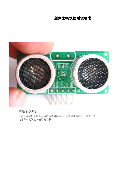
超声波模块使用说明书尊敬的客户:您好!感谢您选用本店的超声波测距模块,为了更快更好的使用本产品,请您仔细的阅读本使用说明书。
一、超声波测距模块简介检测距离:5CM-5M分辨率:5MM数字电平信号,可直接接单片机,无需任何辅助电路,也无需单片机产生任何信号辅助,距离和模块输出信号脉冲长度成正比。
尺寸:43.5*20.5毫米高度:13.8毫米二、超声波测距模块的引脚功能如上图所示:从左到右依次为VCC、控制发射、接收信号(距离信号由此输出)、空脚、GND。
(以上是正确顺序,模块上所标的不对,特此更正)三、测距方式:通过单片机i/o口向模块控制信号接口发送一个>=10US的高电平信号(启动测距功能),等待然后是检测输出信号,输出信号的高电平时间与距离成正比。
然后根据高电平的时间便可计算出距离。
示例程序:///////////////////////////////////////////////////////////////////// ///////////////PIC16F877+DYP-ME007+LCD03example//Written October2005by Gerald Coe,using HITECH PIC16compiler////Note-assumes a20MHz crystal,which is5MHz timer clock//A1:4prescaler is used to give a 1.25MHz timer count(0.8uS per tick)////This code is Freeware-Use it for any purpose you like./////////////////////////////////////////////////////////////////////// //////////#include<pic.h>#include<stdio.h>__CONFIG(0x3b32);#define trig RB0#define echo RB1void clrscn(void);//prototypesvoid cursor(char pos);void print(char*p);void setup(void);unsigned int get_srf04(void);char s[21];//buffer used to hold text to printvoid main(void){unsigned int range;setup();//sets up thePIC16F877I2C portclrscn();//clears the LCD03disply cursor(2);//sets cursor to1st row of LCD03sprintf(s,"SRF04Ranger Test");//text,printed into our bufferprint(s);//send it to the LCD03while(1){//loop foreverrange=get_srf04();//get range from srf04 (round trip flight time in0.8uS units)cursor(24);//sets cursor to2nd row of LCD03sprintf(s,"Range=%dcm",range/72);//convert to cmprint(s);//send it to the LCD03cursor(44);//sets cursor to3rd row of LCD03sprintf(s,"Range=%dinch",range/185);//convert to inchesprint(s);//send it to the LCD03TMR1H=0;//52mS delay-this is so that the SRF04ranging is not too rapidTMR1L=0;//and the previous pulse has faded away before we start the next oneT1CON=0x21;//1:4prescale and runningTMR1IF=0;while(!TMR1IF);//wait for delay timeTMR1ON=0;//stop timer }}unsigned int get_srf04(void){TMR1H=0xff;//prepare timer for10uS pulse TMR1L=-14;T1CON=0x21;//1:4prescale and runningTMR1IF=0;trig=1;//start trigger pulsewhile(!TMR1IF);//wait10uStrig=0;//end trigger pulseTMR1ON=0;//stop timerTMR1H=0;//prepare timer to measure echo pulseTMR1L=0;T1CON=0x20;//1:4prescale but not running yetTMR1IF=0;while(!echo&&!TMR1IF);//wait for echo pulse to start(go high)TMR1ON=1;//start timer to measure pulsewhile(echo&&!TMR1IF);//wait for echo pulse to stop(go low)TMR1ON=0;//stop timerreturn(TMR1H<<8)+TMR1L;//TMR1H:TMR1L contains flight timeof the pulse in0.8uS units}void clrscn(void){SEN=1;//send start bitwhile(SEN);//and wait for it to clearSSPIF=0;SSPBUF=0xc6;//LCD02I2C addresswhile(!SSPIF);//wait for interruptSSPIF=0;//then clear it.SSPBUF=0;//address of register towrite towhile(!SSPIF);//SSPIF=0;//SSPBUF=12;//clear screenwhile(!SSPIF);//SSPIF=0;//SSPBUF=4;//cursor offwhile(!SSPIF);//SSPIF=0;//PEN=1;//send stop bitwhile(PEN);//}void cursor(char pos){SEN=1;//send start bitwhile(SEN);//and wait for it to clearSSPIF=0;SSPBUF=0xc6;//LCD02I2C addresswhile(!SSPIF);//wait for interruptSSPIF=0;//then clear it.SSPBUF=0;//address of register to write towhile(!SSPIF);//SSPIF=0;//SSPBUF=2;//set cursorwhile(!SSPIF);//SSPIF=0;//SSPBUF=pos;//while(!SSPIF);//SSPIF=0;//PEN=1;//send stop bitwhile(PEN);//}void print(char*p){SEN=1;//send start bitwhile(SEN);//and wait for it to clearSSPIF=0;SSPBUF=0xc6;//LCD02I2C addresswhile(!SSPIF);//wait for interruptSSPIF=0;//then clear it.SSPBUF=0;//address of register to write to while(!SSPIF);//SSPIF=0;//while(*p){SSPBUF=*p++;//write the datawhile(!SSPIF);//SSPIF=0;//}PEN=1;//send stop bitwhile(PEN);//}void setup(void){unsigned long x;TRISB=0xfe;//RB0(trig)is outputPORTB=0xfe;//and starts lowTRISC=0xff;PORTC=0xff;SSPSTAT=0x80;SSPCON=0x38;SSPCON2=0x00;SSPADD=50;//SCL=91khz with20Mhz Oscfor(x=0;x<300000L;x++);//wait for LCD03to initialise}注:只是提供一个编程思路,可能还需要自己动手编程,没有其他程序了。
巴卢夫超声波传感器说明书
BUS Ultrasonic SensorsPrecise – simple and reliable TouchControl2Use maximumprecision with Balluffultrasonic sensors. With over 50 years of sensor experience, Balluff is a leading globalsensor specialist with its own line of connectivity products for everyarea of factory automation. Balluff is based in Germany and has atight international network of 54 representatives and subsidiaries.Balluff stands for comprehensive systems from a single source, con-tinuous innovation, state-of-the-art technology, highest quality, andgreatest reliability. That's not all: Balluff also stands for exceptionalcustomer orientation, customized solutions, fast worldwide service,and outstanding application assistance.High-quality, innovative products – certified in accordancewith DIN ISO 9001:2008 (EN 29001) – are a secure foundation foroptimized value creation for our customers.Whether electronic and mechanical sensors, rotary and linear trans-ducers, identification systems or optimized connection technologyfor high-performance automation, Balluff masters not only the entiretechnological variety with all of the different operating principles, butalso provides technology that fulfills regional quality standards andis suitable for use worldwide. Wherever you are in the world, Ballufftechnology is never far away. You won't have to look far for younearest Balluff expert.Balluff products increase performance, quality and productivityaround the world every day. They satisfy prerequisites for meetingdemands for greater performance and cost reductions on the globalmarket. Even in the most demanding areas. No matter how stringentyour requirements may be, Balluff delivers state-of-the-art solutions.Ultrasonic Sensors Precise – simple and reliableRegardless of color and materialBUS ultrasonic sensors are perfect for distance measurement or position detection of granules, fluids and powders. They measure fill levels, heights and sag without making contact as well as count and monitor the presence of objects.They are extremely versatile, operate independently of color and sur-face finish, and are not affected by transparent objects that generate strong reflections.Ultrasonic sensors are precision all-rounders designed for critical situations. Dust, dirt and steam do not pose a problem.Broad detection range – high precisionTheir detection range extends from 20 mm to 8 m, meaning that even longer object distances can be handled without problem. Their high resolution and small blind zones ensure extreme precision. Integral synchronization means that the sensors do not interfere with one another.Switching and analog variantsOur BUS ultrasonic sensors differ form one another in their output signal. Each series is available as a switching or analog version, whereby all analog versions are available with voltage or current output (0...10 V or 4...20 mA). The BUS M30 includes variants with two switching outputs, one switching and one analog output or two switching outputs and one analog output so that one sensor can adopt the function of a second sensor.IO-LinkBUS 18M sensors with push/pull output are equipped with anIO-Link interface that enables a change from SIO mode to IO-Link mode.Table of contents 3 Media 4 Industries, application areas 5 Application areas, sensor selection 6 Modes 7 M30 tubular-style housing 8 M18 tubular-style housing 10 R06 block-style housing 12 M12 tubular-style housing 14 Q80 block-style housing 1534Ultrasonic SensorsMediaLiquidsClear water, cloudy liquids, oils or black coffee — ultrasonic sensors can be used with nearly any liquid. The liquid surface should have no foam.ColorsRed, green, yellow or blue — all make no difference to Balluff ultrasonic sensors: they reliably detect all colors.ContrastsBlack objects against a black background or white on white — even with weak contrasts, our BUS sensors measure without ifs and buts.Transparent layersGlass plates, Plexiglas and razor thin foils — BUS ultrasonic sensors reliably detect transparent layers.Material surfacesWhether velvet, wool or leather — nearly all clothing materials can be simply detected with our BUS ultrasonic sensors.Surfaces of bulk materialsFine sand, shavings or coarse-grainedmaterials — in the areas of fill-level measure-ment, our ultrasonic sensors are unbeatable.The all-rounders, even for difficult environmentsBecause the distance to the object is de-termined via a sound transit time, ultrasonic sensors have excellent background suppres-sion. With their transit time measurement, ultrasonic sensors can record the measuredvalue with highly-precise resolution. Some sensors to even 0.025 mm.The sensors are able to measure in dusty air or through paint spray mist. Nearly all materi-als that reflect the sound are detected. Eventhin foils, crystal clear materials and different colors are no problem for ultrasonic sensors. Thin deposits on the sensor membrane do not affect sensor function.Ultrasonic SensorsIndustries, application areasHandling and automation Bottling and packaging Automotive industryBUS ultrasonic sensors are particularly wellsuited for the following industries■■Handling and automation■■Specialty machine construction■■Automotive industry■■Bottling and packaging■■Pharmaceutical industry■■Plastic and rubber industry■■Timber and furniture industry■■Paper and printing industry■■Conveying■■Commercial vehicles■■Scales■■Agricultural machinery■■Food processing machinery■■Office and information technology■■Construction andbuilding material machinery■■Textile machineryUltrasonic sensors can be used in many application areasOther applications on the next pageHeight andwidth measurementThrough the use ofmultiple BUS M30 orBUS _18M ultrasonicsensors, three-dimen-sional measurements canbe made for everythingfrom small boxes to largecartons.Foil tear monitoringUltrasonic sensorswith switching outputcan be used for foil tearmonitoring. If largewaves are formed in thefoil, the sensor shouldbe operated as a diffusereflective sensor. Thisoperating mode functionsreliably even if the soundis reflected by waves inthe foil.Detection of peopleIf people need to bedetected, a sensorshould be used that hasan operating scanningrange that is considerablygreater than the requiredmeasurement distance.The greater the operatingscanning range, the lowerthe ultrasonic frequency.And the better absorbentpieces of clothing, suchas wool, can be detected.Presence verificationBUS detect filled orempty pallets andmeasure the content oftransport containers. If abox or a container is tobe inspected with multiplesensors, they can besynchronized with eachother.Robot positioningDue to their smalldimensions, BUS areideally suited for exactlypositioning robot arms:BUS_18M ultrasonicsensors in threadedsleeve and BUS R06K inblock-style housing. 56The red areas are measured with a thin round rod (Ø 10 mm or 27 mm, depending on sensor type) and show the typical working range of a sensor.To obtain the blue areas, a plate is moved into the sound fields from the side. In doing so, the optimum angle of the plate to the sensor is set. This is thus the maximum detection range of the sensor.It is not possible to evaluate ultrasound reflections outside of the blue sound cones.Detection rangesDefinitions■■Blind zoneThe blind zone defines the smallest reliable scanning range of the sensor. There must be no objects or interfering reflections within the blind zone, as measurement errors may otherwise occur.■■Operating scanning rangeThe operating scanning range is the typical working range of a sensor. For objects with good reflective properties, it can also be used up to its limiting scanning range.■■Detection rangeThe detection range is measured using various standard reflectors.ObjectScanning rangeLimiting scanning rangeSensor selectionImportant selection criteria for an ultrasonic sensor are its scanning range and the associated, three-dimensional detection range.Fill-level monitoring In silos, bunkers, contain-ers – for all bulk materials (e.g., sand, gravel, coal, grain), our ultrasonic sen-sors are ideal.PositioningWhen scanning glass plates or other smooth and flat surfaces, make certain that the ultra-sound strikes the surface at a right angle.Object detectionBUS ultrasonic sensors sort containers and parts with different heights. BUS count objects. And with absolute reliability.Wire-breakage monitoringWhen winding and unwinding a wire rope, ultrasonic sensors with analog output detect its position on the layer.Stack-height detection Whether wooden boards, glass plates, paper or color plastic plates, BUS ultrasonic sensors measure stack heights with high precision.Ultrasonic SensorsModesThe ultrasonic sensor as a diffuse reflective sensor is theclassic operating mode. Compared to other sensor principles, it hassuperior background suppression. During operation, the switchingoutput is set as soon as the object is located within the set switchingdistance. The switch point has a hysteresis. The operating mode issuitable for, e.g., counting objects on a conveyor belt or for perform-ing presence verification.The ultrasonic sensor in window mode is an extended functionof the ultrasonic diffuse reflective sensor. In this case, the switchingoutput can only be set if the object is located within a window thatis defined by two window limits. This can be used to monitor, e.g.,the correct bottle size in a bottle crate. Bottles that are too tall or tooshort are sorted out. Window mode and the diffuse reflection ultra-sonic sensor can be set on all ultrasonic sensors that are equippedwith teach-in.The function of the diffuse reflection ultrasonic sensor is similar to that of a photoelectric sensor. Any reflector, such as a metal sheet, is sufficient. In window mode, the ultrasonic sensor is set so that the permanently mounted reflector lies within the window. The ultrasonic sensor returns a signal as soon as an object fully covers the reflector. It plays no role here whether the object completely absorbs or reflects away the sound. This operating mode is therefore used for materials than can be only poorly reflected, such as foam, or for scanning objects with irregular surfaces.Ultrasonic sensors with analog output output the measured dis-tance value as a voltage that is proportional to distance (0...10 V) or as current that is proportional distance (4...20 mA). For the ultrasonic sensors with analog output, the sensor-near and sensor-distant window limits of the analog characteristic as well as a rising or falling characteristic can be set. Depending on the sensor model and win-dow width, the resolution is between 0.025 mm and 0.36 mm. Ultrasonic sensors with IO-Link enable gapless communication through all levels of the system architecture: from the sensor to the top fieldbus level. Transmission of the measured distance value to the controller is bit serial.Set windowSetanalog windowSetwindowReflector Set switching distance7Ultrasonic SensorsM30 tubular-style housingInspecting transport boxes for completeness Performance shows up on conveyor belts. Multiple ultrasonic sensors simultaneously monitor transport containers for completeness. Reflective, transparent or different-colored surfaces are reliably detected. Inmultiplex operation, mutual interference of the sensors is prevented.TouchControlWith TouchControl, all settings are made on the sensors. The three-digit LED indicator continuously displays thecurrent distance value and automatically switches between mm and cm display. Two buttons are used to call up the configuration and navigate through the self-explanatory menu structure.Scanning range ■■Display with direct, measured value output for immediately visible results■■Numeric setting of the sensor via the display for completely presetting the sensor■■Automatic synchronization and multiplex operation for simultaneous operation of up to ten sensors■■5 scanning ranges with a measuring range from 30 mm to 8 m ■■1 or 2 switching outputs in PNP- or NPN-design ■■Analog output 4...20 mA and 0...10 VAutomatic changeover between current and voltage output ■■Analog output plus switching outputfor measurement that is proportional to distance with an additional limit value ■■Teach-in via 2 buttonsfor simple, menu-driven commissioning8Ultrasonic SensorsM30 tubular-style housingYou can find additional electrical accessories in our catalog Industrial Networking and Connectivity .You can find additional mechanical accessories in our catalog Accessories Line .9Ultrasonic SensorsM18 tubular-style housingControl foil sag and monitor roll diameterUsing an ultrasonic sensor with analog output, the material on a roll or a coil is detected and the roll drive or a brake readjusted. Another sensor with analog output readjusts the material infeed at the dancer roller as a function of the cable loop.■■Variant with 90° angled headfor individual installation situations ■■IO-Link interfacefor supporting the new industrial standard■■Automatic synchronization and multiplex operation for simultaneous operation of up to ten sensors■■4 scanning ranges with a measuring range from 20 mm to 1.3 m ■■1 push/pull switching output PNP- or NPN-switching ■■Analog output 4...20 mA or 0...10 V for analog distance measurements ■■Teach-in via control line (pin 5)IO-Link — the new standardWith the IO-Link interface, the prerequisites are filled for gapless communication through all levels of the system architecture all the way to the sensor. Commission-ing and maintenance of a machine are simplified and productivity increased.10Ultrasonic SensorsM18 tubular-style housingYou can find additional electrical accessories in our catalog Industrial Networking and Connectivity .You can find additional mechanical accessories in our catalog Accessories Line .BUS M18… straight BUS W18… angled11Ultrasonic SensorsR06 block-style housing■■Small ultrasonic sensor in block-style housing makes possible completely new solutions■■Same construction as many optical sensors a true alternative in critical applications ■■Option for focusing attachment for challenging measurement tasks■■■■1 switching output in PNP or NPN design ■■Analog output 4...20 mA or 0...10 V ■■Teach-in via a buttonFill-level measurement in narrow containersOn a rotary indexing table, narrow containers are filled with liquid or solid media. The ultrasonic sensor then checks the exact filling level.Focusing attachmentFor fill-level measurement through tiny openings with diameters to 5 mm, the sensor with focusing attachment is positioned directly over the measure-ment location. The tightly bundled sound field is incident exactly on the location that is to be measured.The blind zone of the sensor lies within the focusing attachment, makingmeasurement possible starting directly from the sound outlet.Comment: Can be used with BUS R06K1..-02/007-.. and BUS R06K1..-02/015-.. for measurements inboreholes and filling levels as well as for scanning circuit boards or highly transparent foils.12Operating scanning ranges 20–70 mm and 20–150 mm Operating scanning range 120–700 mmUltrasonic SensorsR06 block-style housingYou can find additional electrical accessories in our catalogIndustrial Networking and Connectivity .You can find additional mechanical accessories in our catalog Accessories Line .13Ultrasonic SensorsM12 tubular-style housing■■Stainless steel housing■■Measuring range from 25 mm to 200 mm ■■1 switching output in PNP or NPN design ■■Teach-in via line (PIN 2)You can find additional electrical accessories in our catalog Industrial Networking and Connectivity .You can find additional mechanical accessories in our catalog Accessories Line .Monitoring of packagesHigh hygienic requirements in the food industry place special demands on sensor technology. The ultrasonic sensor reliably monitors the proper sealing of packages and thereby ensures uniform quality.14Fill-level monitoring in silosThe fill level of bulk materials in a container is detected by a continuous measurement with ultrasonic sensors. The fill level can optionally be output by an analog signal or with two switching signals – as min./max. value.Ultrasonic SensorsQ80 block-style housing■■Measuring range from 600 mm to 6000 mm ■■2 switching outputs in PNP- or NPN-design ■■Analog output 4...20 mA or 0...10 V ■■Teach-in via line (PIN 5)You can find additional electrical accessories in our catalog Industrial Networking and Connectivity .15Balluff GmbHSchurwaldstrasse 973765 Neuhausen a.d.F .GermanyPhone +49 7158 173-0Fax +49 7158 5010******************Object DetectionLinear Position SensingFluid SensorsIndustrial IdentificationIndustrial Networking and ConnectivityAccessoriesServiceDoc. no. 892815/Mat. no. 227188 E Edition 1210; subject to changes.。
超声波(一体外贴式)油位传感器用户手册

3
THINKTEC
厦门忻德信息技术有限公司
1. 产品介绍
超声波一体外贴式油位传感器(型号:TUB)是一款为企业的车队管理者设计的油量监控设备, 可用于防范偷油、优化运营成本、优化司机驾驶行为、辅助统计决策等。传感器利用超声波探头来探 测油位高度,再通过主机的内置程序对油量高度信号进行智能处理,最后将油量信息通过 GPS 发送到 系统平台,解析后生成油量报表。传感器支持串口与模拟量输出,方便和车机的对接,可轻松将传感 器接入后台监管系统。
3.3 接线定义
延长线接线定义:
引脚 1 2 3 4A) SGND V+ V-
说明 串口输出 串口输入 信号地 电源输入正极 电源输入负极
3.4 串口如何使用
当超声波油位传感器通过 RS232 与车机连接时,需将传感器的黄线与车机的 Rx 连接,传感器的蓝线与车
机的 Tx 连接,传感器的棕线与车机的 GND 连接; 传感器的串口可连接电脑
(棕) (蓝)(黄)
DB-9 母头
5
THINKTEC
3.5 辅助安装显示屏介绍
辅助安装显示屏
3.6 胶水使用说明
AB胶
小瓶装
大瓶装
3.7 耦合剂使用说明
耦合剂
厦门忻德信息技术有限公司
说明 1、用于油箱材质、油箱高度的参数设置 2、用于查看回波数、高度、状态码
拌均匀(搅拌时间 1 分钟左右) 粘保护壳:分别推出一格 A 与 B 到保护壳表面,充
分搅拌均匀(搅拌时间 1 分钟左右) AB 胶的初步固化时间为 6~10 分钟 AB 胶按 1:1 的体积比例混合 使用时,每次推出约 1 厘米长度的胶体 粘探头:推出约 1 厘米长度的胶体到探头表面,充
超声波物位计使用说明书.doc

超声波物位计菜单简易设置操作说明本公司生产的超声波物位计,使用全中文的菜单,进行简易的设置,就能满足客户不同的需求。
正常情况下,按照说明书的安装要求,安装好设备后,只需要设置以下几个参数,设备就可以正常使用了。
面板上有三个按键,通过这三个按键可对仪表进行调试.调试后液晶屏幕上显示测量值.SET键键◇进入菜单项◇移动光标◇确认菜单项◇选择菜单项◇确认参数修改◇参数修改(1)仪表通电显示后,长按设置键(SET)两秒进入一级菜单。
菜单模式有:专家设置模式和简易设置模式。
简易设置模式的菜单查询表,如下表所示专家设置模式的菜单查询表,见“附录:超声波物位计工程师菜单查询表”.(2)选择测量模式:测量模式分距离测量和物位测量。
出厂默认为物位测量.(3)将探头的高度值输入到“参考零点”。
(探头高度为探头发射面到罐底或池底的距离)①距离测量模式下,参考零点设置没有意义,量程高点、量程低点的位置参见附图1.1。
②物位测量模式下,参考零点、量程高点、量程低点的位置参见附图1。
2。
附图1.1 距离测量示意图附图1。
2 物位测量示意图量程低点:参考平面到该位置的距离值。
当量程低点高于参考平面时数值为正,低于参考平面时数值为负.液位在该位置时输出4mA电流.量程高点:参考平面到该位置的距离值.当量程高点高于参考平面时数值为正,低于参考平面时数值为负。
液位在该位置时输出20mA电流。
(4)带继电器工作的:进入报警设置选项,设置三个参数:①报警模式:选择高位报警、低位报警或者关闭。
②报警值:高位报警:液位高于报警值时报警低位报警:液位低于报警值时报警③回差值:回差值是为了防止测量误差引起在报警点附近报警开关反复跳动.高位报警状态:液位低于(报警值-回差值)时解除报警低位报警状态:液位高于(报警值+回差值)时解除报警(5)探头选择、参数校正、算法选择项请在专业技术人员指导下进行设置。
(6)设备安装完毕,必须真正单独接地,不要与电气箱或者仪表箱的公用地接地.(7)建议:超声波物位计在与变频器、PLC等有干扰的设备连接时,电源部分要加隔离变压器,信号部分要加信号隔离器,并做可靠接地处理. ★信号线不可与动力线、电源线在同一个线槽内,要单独穿金属管安装,或者是远离动力线和电源线安装,在没有穿管安装的前提下,距离动力线、电源线距离至少1米以上。
超声波中文说明书

超声波液面探测仪简介注:超声波液面探测仪只能按本手册描述的方法使用。
超声波液面探测仪由传感器和相关电路组成一体,用于测量开敞式容器和密封容器的液面高度。
传感器涂有特氟龙,可广泛用于各行各业,尤其是食品和化学工业。
传感器包含超声波变送器和温度感应元件。
变送器发出超声波脉冲,物质对每个脉冲都有回声,变送器接收回声并用“Milltronics 声音智能〞技术进展处理。
真假回声进展过滤。
超声波传到物质再回来的时间和温度补偿计算后转化为距离,用毫安单位输出。
安装工作环境探测仪工作环境温度在规定的范围内,适合传感器外壳和被测物质工作。
前盖应活动自如,以便于编程、走线和显示。
探测仪应防止接近高电压、高电流、接触器和SCR控制驱动器。
安装位置传感器安装后,它和被测液面之间应在垂直方向上有清晰的声音通道。
传感器声音通道应防止充油口、粗糙墙面、裂缝、横档等。
注:传感器安装后,其外表据最高液面应有25厘米以上。
拧螺纹探测仪有三种螺纹:2〞NPT,BSP和PF2。
注:把传感器放入安装口之前应确认两边的螺纹类型相匹配。
法兰配适器〔选项〕探测仪可配75毫米〔3〞〕法兰配适器,法兰有3〞ANSI、DIN 65PN 10 和JIS 10K3B 等型号。
连接电缆输入:A.关上盖子,翻开电缆入口两端。
B.拧松螺丝,翻开盖子。
C.接入电缆。
D.连接环状电路。
E. 关上盖子。
拧紧螺丝,扭力1.1到1.7N·m。
系统图联接到DAQ使用启动·探测仪正确安装后〔距液面0.25米到5米〕,通电。
·启动时探测仪显示如下:·默认状态为RUN状态,即传感器外表到被测物的距离。
如下图:·如默认状态不是RUN状态,参见“使用状态〞章。
调校进展输出调校后,输出值与液面高度可为正比或反比。
正比范围反比范围高液面=20毫安高液面=4毫安低液面=4毫安低液面=20毫安注:可按正比或反比进展调校。
调校方法:确定与输出值对应的距离后,分别按“4〞和“20〞键。
科学实验用40kHz超声传感器说明书
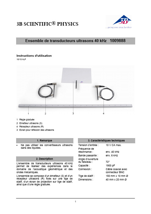
3B SCIENTIFIC ®PHYSICS1Instructions d'utilisation10/15 ALF1 Règle graduée2 Emetteur ultrasons (S) 4Récepteur ultrasons (R)3Ecran pour réflexion des ultrasonsNe pas utiliser lesconvertisseurs ultrasons dans des liquides.L’ensemble de transducteurs ultrasons 40 kHz permet de réaliser des expériences dans le domaine de l’acoustique géomét rique et des ondes mécaniques.L’ensemble se compose d’un émetteur (S) et d’un récepteur ultrasons (R) fixés sur une tige de statif, d’un écran de projectionsur tige de statif, ainsi que d’une règle graduée.Tension d’entrée : 10 V CA max. Fréquence de résonnance :env. 40 kHz Bande passante : env. 6 kHzAngle d’ouverture du faisceau : 72°Capacité : 1900 pFConnexion : Câble coaxial avecconnecteur BNC Tige de statif : 150 mm x 10 mm Ø Dimensions : 40 mm x 20 mm Ø3B Scientific GmbH ▪ Rudorffweg 8 ▪ 21031 Hambourg ▪ Allemagne ▪ Sous réserve de modifications techniques © Copyright 2015 3B Scientific GmbH1 générateur de fonctions FG 100 @230 V 1009957 ou1 générateur de fonctions FG 100 @115 V 1009956 1 oscilloscope analogique 2x30 MHz 1002727 3 socles de serrage, 0,5 kg 1001046 1 câble HF 1002746 1 adaptateur BNC en T 1002752 1 adaptateur BNC / fiches mâle 4 mm 10027515.1 Réglage de la fréquence de résonnance ∙ Disposer l’émetteur et le récepteur ultrasonsà courte distance l’un en face de l’autre.∙Brancher l’émetteur sur la sortie du générateur HF et régler la fréquence sur 40 kHz.∙ Brancher le récepteur sur l’oscillosc ope.∙Observer le signal du récepteur et maximiser l’amplitude des signaux par des réglages précis de la fréquence.5.2 Exemple d'expérience∙ Disposer l’émetteur et le récepteur ultrasonscôte à côte devant l’écran.∙ Brancher l’émetteur sur la sortie dugénérateur HF et régler la fréquence de résonnance (cf. par. 5.1).∙ Brancher le récepteur sur l’oscilloscope.∙ Déplacer l’écran et observer l’amplitude et ledéphasage entre les signaux.Fig. 1 Montage expérimental - Réglage de la fréquence de résonnanceFig. 2 Montage expérimental - Réflexion des ondes ultrasonores sur l'écran de projection。
超声波传感器URM37 V4.0使用说明

一、简介URM37 V3.2上已经很好的实现了超声波开关量、串口(TTL和RS232电平可选)、脉冲输出功能、模块还可以控制一个舵机的旋转组成一个空间超声波扫描仪。
为了方便客户使用模块,在出厂时可以根据客户需要配置其相应的参数,也可以根据客户具体需求定制软件,使他成为一个专用的模块。
当前版本URM37 V4.0在V3.2基础上对功能进行了升级使其具有更好的智能功能,机械尺寸与引脚接口以及通信命令兼容V3.2,在V3.2基础上做了如下更改:●串口电平选择由原来的跳针方式改为通过按键设置,用户可以轻松的选择TTL电平输出或是RS232电平输出(重启之后模式生效)。
●修改了测距算法,使测量盲区减小,精度提高。
●具有模拟电压输出功能,电压和测量距离正比。
●宽电压支持+3.3V-5.0V。
●具有电源接反保护功能。
●自动测量时间间隔可修改。
●修改舵机控制角度为0-180,兼容市面大部分舵机。
●测量时长为100ms。
二、产品参数1.产品规格●工作电源:+3.3V~+5.0V●工作电流:<20mA●工作温度范围:-10℃~+70℃●超声波距离测量:●最大测量距离―500cm●最小测量距离―5cm●分辨率-1cm●精度-1%●模块尺寸22mm ×51 mm●模块重量:约25g●超声波一次测量时间为100ms2.技术说明●由于使用了更好的测距处理方法,使测量距离更远更稳定,在测量上完全兼容V3.2,但是我们可以做到在0.3-3M的距离上稳定2mm的精度,如果有需要可以和公司联系定制。
●模块使用RS232串口通讯可靠性更高,同时可以通过电脑串口采集数据,编写通讯程序非常的便捷。
●串口电平工作方式是TTL还是RS232选择方式为按键设置或者软件设置(重启之后模式生效)。
●模块可以通过脉宽输出的方式将测量数据输出,这样使模块使用更简单。
●模块可以预先设定一个比较值,在自动测量模式下,测量距离小于这个值后管脚COMP/Trig输出一个低电平,这样模块能够方便的作为一个超声波接近开关使用。
- 1、下载文档前请自行甄别文档内容的完整性,平台不提供额外的编辑、内容补充、找答案等附加服务。
- 2、"仅部分预览"的文档,不可在线预览部分如存在完整性等问题,可反馈申请退款(可完整预览的文档不适用该条件!)。
- 3、如文档侵犯您的权益,请联系客服反馈,我们会尽快为您处理(人工客服工作时间:9:00-18:30)。
一、简介URM37 V3.2上已经很好的实现了超声波开关量、串口(TTL和RS232电平可选)、脉冲输出功能、模块还可以控制一个舵机的旋转组成一个空间超声波扫描仪。
为了方便客户使用模块,在出厂时可以根据客户需要配置其相应的参数,也可以根据客户具体需求定制软件,使他成为一个专用的模块。
当前版本URM37 V4.0在V3.2基础上对功能进行了升级使其具有更好的智能功能,机械尺寸与引脚接口以及通信命令兼容V3.2,在V3.2基础上做了如下更改:●串口电平选择由原来的跳针方式改为通过按键设置,用户可以轻松的选择TTL电平输出或是RS232电平输出(重启之后模式生效)。
●修改了测距算法,使测量盲区减小,精度提高。
●具有模拟电压输出功能,电压和测量距离正比。
●宽电压支持+3.3V-5.0V。
●具有电源接反保护功能。
●自动测量时间间隔可修改。
●修改舵机控制角度为0-180,兼容市面大部分舵机。
●测量时长为100ms。
二、产品参数1.产品规格●工作电源:+3.3V~+5.0V●工作电流:<20mA●工作温度范围:-10℃~+70℃●超声波距离测量:●最大测量距离―500cm●最小测量距离―5cm●分辨率-1cm●精度-1%●模块尺寸22mm ×51 mm●模块重量:约25g●超声波一次测量时间为100ms2.技术说明●由于使用了更好的测距处理方法,使测量距离更远更稳定,在测量上完全兼容V3.2,但是我们可以做到在0.3-3M的距离上稳定2mm的精度,如果有需要可以和公司联系定制。
●模块使用RS232串口通讯可靠性更高,同时可以通过电脑串口采集数据,编写通讯程序非常的便捷。
●串口电平工作方式是TTL还是RS232选择方式为按键设置或者软件设置(重启之后模式生效)。
●模块可以通过脉宽输出的方式将测量数据输出,这样使模块使用更简单。
●模块可以预先设定一个比较值,在自动测量模式下,测量距离小于这个值后管脚COMP/Trig输出一个低电平,这样模块能够方便的作为一个超声波接近开关使用。
●模块提供一个舵机控制功能,在非自动测量模式下,可以和一个舵机组组成一个180度测量组件用于机器人扫描0~180度范围障碍物。
●模块内带温度补偿电路提高测量的精度。
●模块内带123字节内部EEPROM,可以用于系统记录一些调电不丢失的系统参数。
●模块内带一个温度测量部件,可以通过通讯口读出分辨率0.1摄氏度的环境温度数据。
●具有电源接反保护功能。
●自动测量时间间隔可修改。
●具有模拟电压输出功能,电压和测量距离成正比。
3.引脚说明测距的模式有三种:一PWM触发测量模式、二自动测量模式、三串口被动测量。
还具有以下特性:模拟量输出(和测量距离正比)、温度读取、和串口电平方式设置(TTL或者RS232电平)、内部EEPROM掉电不丢失数据保存、串口读取EEPROM数据等。
URM37出厂时我们进行了严格的测试,用户购买到之后可根据自己的需求进行相关设置,首先是串口电平方式的设置(TTL或者RS232电平),设置好之后我们就可以通过串口对模块进行访问,然后设置测距模式(对内部EEPROM地址0x02写入数据),之后就可以通过MCU或者PC对超声波模块驱动。
注意:URM37 V4.0的出厂设置为串口TTL电平、测量模式为PWM触发测量方式、比较距离为0、自动测量时间间隔为25ms,内部EEPROM内数据全部为0x00,EEPROM地址0x00~0x04内存的数据为系统保留配置字,用户需谨慎操作。
1.模式/参数设置方法由于该模块有测距模式,电平选择等需要选择,因此这里将简单介绍相关的模式设定方法。
(1)EEPROM各地址配置字节含义关于模式设定,用户可以了解一下URM37内部EEPROM中,各存储单元中配置字节的含义(详见通信协议)。
地址意义0x00 比较距离高8位0x01 比较距离低8位0x02 测量模式(对模式寄存器写入0xaa自动测量模式,其他非0xaa数据都是PWM被动测量模式)0x03 串口工作模式(写入数据0x00为TTL电平,也是默认工作方式哦,写入数据0x01为RS232电平,当然如果用户对0x03这个地址写入其他数据,会被修改为默认方式TTL电平)0x04 自动测量时间间隔(默认最小间隔为25ms,写入数据为八位16进制,最小单位为ms。
例如写入64,即为100ms)(2)按键选择串口电平模式要和模块通信,首先需要进行的就是串口电平的选择(TTL电平、RS232电平)。
按下模块上的按键,指示灯亮,按住不动1s过后,设置成功,指示灯灭。
松开按键,重新上电。
即可更改串口输出模式。
再次上电后指示灯出现一长一短闪则为TTL电平输出,一长两短闪为RS232电平。
串口电平的选择,也可以通过对EEPROM地址0x03写入数据(见上表)。
注意:禁止在RS232工作模式下,将传感器接到TTL 适配器上,这样会造成器件损坏。
反之亦然!(3) 上位机软件选择测量模式当你按照上图连接好模块后,就可以使用我们的“URM37 V3.2伴侣”对模块进行在线测试了,当然我们需要按照前面的按键设置串口电平方式改变一下串口的工作模式,按照现在的配图我需要串口工作在RS232电平模式下。
软件的使用极其简单:先保证电脑上没有其他软件占用串口,然后运行伴侣,先选择COM口,再点击“打开串口”,右边窗口选择探测功能,选择“16位温度读取”可以进行温度测量,选择“16位距离读取”可以进行距离测量,“控制指令”窗口同时显示将要发送的指令,点击“启动功能”便完成操作。
此时,“返回数据”窗口中间两位显示的是16进制数据,软件下方状态栏内也会显示出温度及距离的10进制数据。
该软件使用方便、数据直观。
如果你还购买了我们的专用舵机,便可以使用舵机控制部分。
如图所示,在“舵机角度”窗口内选择要执行的角度,同时在选择“16位距离读取”,然后点击“启动功能”,舵机便旋转到相应的角度上,同时超声波测量该方向上障碍物的距离。
由此URM37V4.0配合舵机就可以完成空间障碍物扫描功能。
测量模式的切换通过给内部EEPROM地址0x02写入0xaa的数据即切换到自动测量模式。
串口发送数据0x44 0x02 0xaa 0xf0 .注意:测量模式的选择,也可以通过修改程序达到。
2.PWM触发模式测距使用教程硬件连接:●Vcc (Arduino) -> Pin 1 VCC (URM V4.0)●GND (Arduino)-> Pin 2 GND (URM V4.0)●Pin 3 (Arduino) -> Pin 4 ECHO (URM V4.0)●Pin 5 (Arduino) -> Pin 6 COMP/TRIG (URM V4.0)●Pin A0 (Arduino) -> Pin 7 DAC (URM V4.0)通过Arduino给超声波传感器Pin 6 COMP/TRIG发低电平触发脉冲启动测量后读取测量数据。
方法一:读取Pin 4 ECHO低电平持续的时间(通过pulseIn函数),测量到的距离数据以脉宽方式输出一个低电平脉冲,每50US代表1厘米,可以通过对这个低电平脉冲宽度的测量读取距离数据。
当测量无效时将返回一个50000US的脉冲表示这次的测量是无效的。
方法二:读取Pin 7 DAC的模拟量(使用analogeRead函数),读得的模拟电压值和测量距离成正比6.8mV/cm,模拟值*0.718即为距离值(单位cm)3.自动测量模式使用教程(1)设置模块为自动测量模式,设置方法:通过上位软件或者单片机串口对模块内部EEPROM 0x02地址写入数据0xaa即可切换到自动测量模式,对0x04地址写入一个8位的16进制数即可修改测量时间间隔。
(2)超声波传感器每隔一定时间间隔(由0x04地址内数据决定)自动测量数据,并将测量到的数据和比较值(由0x000x01地址内数据设定)做比较,如果测量距离等于或者小于比较值,COMP/TRIG脚输出低电平。
(3)通过控制器读取Pin 4 ECHO低电平持续时间获得距离值,每50US代表1厘米。
硬件接线图如下:电源、Pin 4 ECHO(读取测量数据)、RXD、TXD(用于单片机串口设置自动测量模式参数,如单片机通过串口发送0x44,0x02,0xaa,0xf0给超声波模块,即设定超声波模块为自动测量模式)4.串口被动测量模式使用教程串口被动测量模式不需要特别设定,任何时候都可以给超声模块串口发送命令来获取超声波模块测量的数据。
通信命令格式为:命令+数据0+数据1+校验和;通信模块串口波特率9600,无奇偶校验,一位停止位。
具体通信协议如下:(1)读取温度数据指令*发送:0x11+NC+NC+SUM*返回:0x11+温度高+温度低+SUM命令启动一次读取命令,测量温度完毕后模块发出带相同命令头的数据加两字节的温度数据:0x11+温度高+温度低+SUM(SUM代表效验和,NC代表任意数据)。
温度高字节的高4位代表温度正负,当高4位都是1时说明是负温度,当高4位都是0时是正温度,除去温度高字节的高4位后是12位的温度。
分辨率0.1度,每个数字代表0.1摄氏度。
当测量无效时返回的温度高位和低位数据都是0xff。
例如:发送:0x11 0x00 0x00 0x11返回:0x11 0x00 0xFA 0x0B效果:返回的数据0xFA就是测量到的温度即温度为25.0度(2)读取距离数据指令发送:0x22+度数+NC+SUM返回:0x22+距离高+距离低+SUM度数是控制舵机先旋转到一个度数后再进行测距。
180度分为46个角度,每个角度4度,数字范围是十进制0到45,如果数字超过45电机将不动作。
上电初始,舵机将旋转到当中即0度的位置。
当指令是0时,舵机逆时针旋转到0度,当指令是45时,舵机顺时针旋转到180度。
当测量完毕这时返回的数据是0x22+距离高+距离低+SUM。
当测量无效时返回的距离高位和低位数据都是0xff。
例如:发送:0x22 0x19 0x00 0x47返回:0x22 0x00 0x64 0x86效果:模块上的MOTO输出一个50Hz的方波,控制舵机转到100度(见参考表),返回距离低的数据为0x64,即距离为100cm。
(3)读取EEPROM数据指令0x33 0x00 0x00 0x33发送:0x33+地址+NC+SUM返回:0x33+地址+数据+SUM发送读取指令后,返回的数据即内部EEPROM地址的数据(4)写入EEPROM数据指令0x44 0x02 0x00 0x46发送:0x44+地址+写数据+SUM返回:0x44+地址+写数据+SUM写地址范围包括0-127单元,其中地址0x00-0x04内存储的数据是模块使用的配置字,操作时需谨慎!可以通过读指令来校验数据是否被写入。