切换器使用说明书
至尊A 4x2 HDMI v1.3 切换器说明书
A tlonA4x2 HDMI™ v1.3 SwitcherAT-HDMI-V421. Introduction (1)2. Features (1)3. Operation Controls and Functions (2)3.1 Front Panel (2)3.2 Rear Panel (2)4. Remote Control (3)5. RS-232 Remote Control Protocol (3)5.1 RS-232 transmission format (3)5.2 RS-232 command (4)6. Specifications (4)7. Connection and Installation (4)8. Safety (5)9. Warranty (6)The is a high performance HDMI™ v1.3 Switcher with remote control. It allows your various HDMI™ source to share two HDTV display. Simply pressing one button to select your desired HDMI™ source for display on the HDTV.Each product in this series is compatible to HDMI™ v1.3 specifications, a cutting-age technol-ogy which defines the support to transfer Deep Color (10-bit and 12-bit) video and new loss-less compressed (Dolby TrueHD, Dolby Digital Plus and DTS-HD Master Audio) digital audio, with a high bandwidth up to 225MHz.* HDMI™ 1.3, HDCP1.1 and DVI1.0 compliant Receiver.* Deep color video up to 12bit, 1080p@60Hz.* Four HDMI™ sources to connect up to two HDMI™ displays simultaneously.* Supports DVI source and DVI display by using HDMI™ to/from DVI adaptor cable.* Dolby Digital, DTS digital audio transmission (32-192kHz Fs sample rate).* Supports a wide range of PC and HDTV resolutions from VGA to UXGA and 480i to 1080p. * HDMI™ cable distance test with 1080p resolution: Input/Output source can run up to30M/5.1CH.* Full HDCP Compliant.3.1. Front Panel3.2. Rear Panel1 Remote Control Sensor.2 HDMI™ input Select/Indicator: Press the “Input” button sequentially to switch to your de -sired input (HDMI™ 1 to HDMI™ 4), the LED will illuminate to indicate which input source is selected3 POWER Switch/Indicator: Press the “POWER” button to turn on/off the power, the power LED illuminate in red color means the power is turned on, when the LED not illuminate power is turned off.1 HDMI™ Outputs 1 and 2: Connect each of the output ports to the HDMI™ display. When more than one output connected, the HDMI™ outputs play identical video signal simultane -ously.2 RS232: 9-pin D-Sub connector for connecting to your PC or other control console for remote control.3 HDMI Inputs 1 to 4: Connect each of the input ports to the HDMI or DVI output of your source equipment such as DVD player or set-top-box.4 Power: Plug the 5V DC power supply into this unit and connect the adaptor to AC wall outlet.POWERINPUT 4321123A tlonA1 Power: Press the button to turn on/off the unit.2 Direct input selector:Press 1, 2, 3 or 4 to select the desired input source.The connection between splitter and remote controller with RS-232 modem cable.ns definition of modem cable5.1 RS-232 transmission format:Baud Rate: 9600 bps Data bit: 8 Bits Parity: None Stop Bit: 1 bitDVD 1DVD 2DVD 3STBRS-232 command OperationPOWER 00Select power OFF POWER 01Select power ON PORT 01Select port 1PORT 02Select port 2PORT 03Select port 3PORT 04Select port 45.1 RS-232 transmission format:Frequency bandwidth 2.25Gbps (single link)Input port 4x HDMI female ports Output port 2 x HDMI female portsPower Supply 5VDC/2.6A (US/EU standards, CE/FCC/UL certified)Remote Control Discrete IR remoteDimensions (mm)240(W) x 104(D) x 44(H)Weight(g)0.8 kgs Chassis Material Metal Silk Skin ColorBlackOperating TemperatureOperating from 0°C ~ 48°CHDTV 2HDTV 1SafeguardsTo reduce the risk of electric shock, do not expose this product to rain or moisture.If the wall plug does not fit into your local power socket, hire an electrician to replace your obsolete socket.Do not modify the wall plug.Doing so will void the warranty and safety features.This equipment should be installed near the socket outlet and the device shouldbe easily accesible in case it requires disconnection.PrecautionsFCC Regulations state that any unauthorized changes or modifications to this equipment not expressly approved by the manufacturer could void theuser’s authority to operate this equipment.Operate this product using only the included external power supply. Use of other power supplies could impair performance, damage the product or cause fires.In the event of an electrostatic discharge, this device may automatically turn off. If this occurs, unplug the device, and plug it back in.Protect and route power cords so they will not be stepped on or pinched by anything placed on or against them. Be especially careful of plug-ins, or cord exit points from this product.Avoid excessive humidity, sudden temperature changes or temperature extremes.Keep this product away from wet locations such as bathtubs, sinks, laundries, wet basements and swimming pools.Use only accessories recommended by ATLONA to avoid fire, shock or other hazards.Unplug the product before cleaning. Usea damp cloth for cleaning. Do not use cleaning fluid or aerosols, which could enter the unit and cause damage, fire or electrical shock. Some substances may also mar the finish of the product.Never open or remove unit panels or make any adjustments not described in this manual. Attempting to do so could expose you to dangerous electrical shock or other hazards. It may also cause damage to your AT-HDMI-V42. Opening the product will void the warranty.Do not attempt to service the unit. Instead disconnect it and contact your Authorised ATLONA reseller or contact ATLONA directly.1. LIMITED WARRANTYAtlona Technologies warrants that (a) its products (the “Product”) will perform substantially in accordance with the accompanying written materials for a period of 3 YEARS from the date of receipt and (b) that the Product will be free from defects in materials and workmanship under normal use and service for a period of 3 years. In the event applicable law imposes any implied warranties, the implied warranty period is limited to 3 years from the date of receipt. Some jurisdictions do not allow such limitations on duration of an implied warranty, so the above limitation may not apply to Customer.2. CUSTOMER REMEDIESAtlona Technologies and its suppliers’ entire liability and Customer’s exclusive remedy shall be, at Atlona Technolo-gies’ option, either return of the price paid for the Product, or repair or replacement of the Product that does not meet this Limited Warranty and which is returned to Atlona Technologies with a copy of Customer’s receipt. This Limited Warranty is void if failure of the Product has resulted from accident, abuse, or misapplication. Any replacement Prod-uct will be warranted for the remainder of the original warranty period or 3 year, whichever is longer.3. NO OTHER WARRANTIESTO THE MAXIMUM EXTENT PERMITTED BY APPLICABLE LAW, ATLONA TECHNOLOGIES AND ITS SUPPLI-ERS DISCLAIM ALL OTHER WARRANTIES, EITHER EXPRESS OR IMPLIED, INCLUDING, BUT NOT LIMITED TO IMPLIED WARRANTIES OF MERCHANTABILITY AND FITNESS FOR A PARTICULAR PURPOSE, WITH REGARD TO THE PRODUCT AND ANY RELATED WRITTEN MATERIALS. THIS LIMITED WARRANTY GIVES CUSTOMER SPECIFIC LEGAL RIGHTS. CUSTOMER MAY HAVE OTHER RIGHTS DEPENDING ON THE JU-RISDICTION.4. NO LIABILITY FOR DAMAGESTO THE MAXIMUM EXTENT PERMITTED BY APPLICABLE LAW, IN NO EVENT SHALL ATLONA TECHNOLO-GIES OR ITS SUPPLIERS BE LIABLE FOR ANY DAMAGES WHATSOEVER (INCLUDING WITHOUT LIMITA-TION, SPECIAL, INCIDENTAL, CONSEQUENTIAL, OR INDIRECT DAMAGES FOR PERSONAL INJURY, LOSS OF BUSINESS PROFITS, BUSINESS INTERRUPTION, LOSS OF BUSINESS INFORMATION, OR ANY OTHER PECUNIARY LOSS) ARISING OUT OF THE USE OF OR INABILITY TO USE THIS PRODUCT, EVEN IF ATLONA TECHNOLOGIES HAS BEEN ADVISED OF THE POSSIBILITY OF SUCH DAMAGES. IN ANY CASE, ATLONA TECHNOLOGIES’ AND ITS SUPPLIERS’ ENTIRE LIABILITY UNDER ANY PROVISION OF THIS AGREEMENT SHALL BE LIMITED TO THE AMOUNT ACTUALLY PAID BY YOU FOR THE PRODUCT. BECAUSE SOME JU-RISDICTIONS DO NOT ALLOW THE EXCLUSION OR LIMITATION OF LIABILITY FOR CONSEQUENTIAL OR INCIDENTAL DAMAGES, THE ABOVE LIMITATION MAY NOT APPLY TO YOU.ATLONA2151 O’toole Ave, Ste DSan Jose CA 95131Toll Free: 1-877-536-3976International: 408-954-8782FAX: 408-954-8792Website: E-MAIL:***************。
aten ALTUSCN KL3116 KL3116T LCD KVMP切换器 说明书

用户注意事项
制造商有修改与变更手册所包含的信息、文件和规格表的权利,且不需事前通知。制 造商不会保证、明示、暗示或法定声明其内容或特别否认其对于特殊用途的可销售性 和适用性。本手册所描述的任何被销售与授权的制造商软件亦同。如果在购买后发现 软件程序有瑕疵,购买者(及非制造商、其经销商或其购买商家)将需承担所有因软 件瑕疵所造成的必要服务费用、维修责任及任何偶然事件或间接损害。
ATEN NJ
中国
电话支持
如果您需要电话支持,请拨打:
国际
886-2-8692-6959
北美
ATEN TECH
1-888-999-ATEN
中国
ATEN NJ
1-732-356-1703 400-7080-600
制造商并不担负任何未经授权调整本设备所造成的收音机及/或电视干扰的责任,用 户必须自行修正干扰。
操作前如未正确选择操作电压的设定,制造商将不担负因此所导致任何损害的责任。 使用前请务必确认电压设置为正确的。
iii
KL3116/KL3116T 用户手册
包裝明細
基本包装
KL3116/KL3116T 产品包装说明如下:
RoHS
该产品符合 RoHS 规范。
SJ/T 11364-2006
ii
KL3116/KL3116T 用户手册
用户信息
在线注册
请在我们的在线支持中心注册您的产品:
国际
北美 ATEN TECH
/product_registration
1 附有标准机架安装套件的 KL3116/KL3116T LCD KVMP 切换器 2 定制的 KVM 线缆套装 1 定制的控制端连接线缆套装 1 固件更新线缆 1 电源线缆 1 用户手册 * 1 快速安装卡
HDMI接口KVM切换器用户手册
■ Please do not dismantle the equipment, avoid damaging the internal electrical component.
HDMI Type A x1 (female)
Switch way
Key switch, remote control switch
Automatic scanning interval
Default 5 seconds (time 5~999 seconds adjustable)
Resolution
safety of the user, please observe the following matters during the process of installation, use and maintenance.
■ Please do not use this product in the following places: the place of dust, soot and electric conductivity dust, corrosive gas, combustible gas; the place exposed to high temperature, condensation,wind and rain; the occasion of vibration and impact. Electric shock, fire, wrong operation can lead to damage and deterioration to the product, either;
Atlona 2x16 HDMI 切换器用户指南说明书
.................................................. 6
9.4 Unit Reset
.................................................. 6
10. Applications .................................................. 7
PANEL DESCRIPTION
1. Front Panel
12 3
45 6
7
1. POWER SWITCH. The power switch turns the unit on and off. The LED will illuminate red to indicate that the switcher is ON
9.1 Standby Mode
.................................................. 6
9.2 Power Off Mode
.................................................. 6
9.3 Front Panel Lock
2. Features .................................................. 2
3. Specification .................................................. 2
4. Package Contents
7. IR Extender
.................................................. 4
N6 无缝切换器 用户手册说明书

N6无缝切换器V3.0.0用户手册版权所有©2020西安诺瓦星云科技股份有限公司。
保留一切权利。
非经本公司书面许可,任何单位和个人不得擅自摘抄、复制本文档内容的部分或全部,并不得以任何形式传播。
商标声明是诺瓦科技的注册商标。
声明欢迎您选用西安诺瓦星云科技股份有限公司(以下简称诺瓦科技)的产品,如果本文档为您了解和使用产品带来帮助和便利,我们深感欣慰。
我们在编写文档时力求精确可靠,随时可能对内容进行修改或变更,恕不另行通知。
如果您在使用中遇到任何问题,或者有好的建议,请按照文档提供的联系方式联系我们。
对您在使用中遇到的问题,我们会尽力给予支持,对您提出的建议,我们衷心感谢并会尽快评估采纳。
目录1 产品概述 (1)产品简介 (1)产品特性 (1)2 外观说明 (3)前面板 (3)后面板 (4)产品尺寸 (5)3 应用场景 (6)4 液晶屏菜单操作 (7)操作说明 (7)主界面 (7)屏体配置 (9)4.3.2 输出模式 (9)4.3.3 屏体结构 (10)4.3.4 输出设置 (10)4.3.5 输出接口配置 (11)窗口设置 (11)4.4.1 窗口分屏模板 (11)4.4.2 BKG配置 (12)4.4.3 窗口配置 (13)场景设置 (14)输入设置 (15)画面控制 (15)测试画面 (16)预监选择 (17)高级设置 (18)4.10.2 系统模式 (18)4.10.3 同步模式 (18)4.10.4 AUX (18)4.10.5 Fn键设置 (19)4.10.6 返回主界面时长 (20)4.10.7 工厂复位 (20)4.10.8 HDCP开关 (20)4.10.9 硬件版本 (20)4.10.10 设备自检 (21)4.10.11 关于我们 (21)通讯设置 (21)5 V-CAN控制 (23)6 C1控制 (25)7 常见问题 (27)8 规格参数 (28)1 产品概述产品简介N6是由诺瓦科技自主研发的集视频处理,画面拼接,特效切换和多画面显示的高性能无缝切换器。
SL1 切换器用户手册说明书

WHAT IS THE SL1 SWITCH?• 113CM X 20CM X 2 CM - 45 X 7.8 X 0.8 "• 170 W MAX CONSUMPTION• 3.4 KG - 7.5 LBS• 3000°K TO 5600°K•24 VDC• FLICKER FREE AT ANY FRAME RATE •SL1 V4SL1 AC Power SupplySL1-EPS-V4Battery Mounting Plate SL1-MINI-VL-V4 or ABSL1 Driver SL1-CT-SWWDMX Driver UBB-DMXUSER MANUAL -POWERING OPTIONS• Place the Mount at the center of the SL1 and apply a quarter turn until the spring loaded pin drops in it’s lodging.• If you have purchased the SL1 with the Powerbox, you can attach the Powerbox at the back of the light before attaching the mount :1. Place the SL1 on a flat surface.2. Place the Powerbox on the back of the light, making sure the 4 feet are in their lodging.3. With an Allen Key n°4, screw the 4 spring loaded screw of the Powerbox to the SL1. Make sure the 4 screws are properly attached.• Once the Powerbox is attached you can mount any of the mounts to the Powerbox like you would on the head.1. On/Off2. DMX SWITCH• Switch between local andDMX control3. Local Indicator• If ON, the light is in local control mode 4. DMX Indicator• If ON, the light is in DMX control mode 5. 3200/DMX Addressing• In LOCAL mode, switches the CCT to 3200°K • In DMX mode, allows input ofDMX channel6. 5600/DMX Addressing• In LOCAL mode, switches the CCTto 5600°K• In DMX mode, increments the DMX digit7.DMX Signal• Red : no DMX input• Blinking Green : DMX signal recieved8. COLOR Indicator• If ON, the dimmer controls the CCT9. CCT Display10. SWITCH Button• Switch the function of the dimmer,from CCT control to INTENSITY control11. Intensity Indicator• If ON, the dimmer controlsthe intensity12. Intensity Display13. Dimmer• Changes CCT or intensity14. Power Out• Power out to the SL1 Head light15.Female Plate• Female plate for K1, K2 or HandleMount16. DMX IN - XLR517. DMX OUT - XLR518. Power IN - IEC151381124567910121314161718• Turn on the controls with the ON/OFF button.• power source (AC for the POWERBOX, for the DC/DC drivers).• If you have attached the controls at the back of the light, you can connect the cable-out directly to the controls. If you need to distance the SL1 from its controls, you can add the extension cable.CONTROLLING THE SL1 :SAFETY WARNING : Make sure power is off before connecting or disconnectingthe SL1 to the controls.• To control the brightness of the light, make sure to press the SWITCH button until the “Brightness” indicator is on. You can now control the brightness with the dimmer button.• You can switch the increment from 1% to 0.1% by pressing the dimmer button.• To switch from brightness to color temperature, press the SWITCH button once more until the “Color” indicator is on. You can now control the color of the SL1 with the dimmer button, from 3000°K to 5600°K.In local mode:The SL1 one takes 2 DMX channels, channel one is the brightness, channel 2 the color Setting up the DMX MODE :CONTROLLING THE SL1 (CONTINUED) :• Then, to control the SL1 in DMX, you need to switch from LOCAL to DMX mode. Do this by pressing the button between LOCAL and DMX. The DMX indicator will turn on when in DMX mode.• To setup the DMX address, press the first DMX button (also the 3200°K button). The first digit can be set by pushing the second DMX button (also the 5600°K button).• Press the 3200°K button again to change of digit. Repeat until all of your digits are set.• Once the address is set, the DMX indicator will blink if a DMX signal is received. Otherwise, please check your DMX signal.1. Menu• Go to the general menu 2. Back• Step back in menu• Lock/unlock UBB when pressed for 2secs.3. SWITCH• Change between CCT and intensity control4. CCT• Quickly change from 3200°k to 5600°K• Enter the preset menu to store or recall values5. Dimmer button• Press to change intensity or CCT • Select fine or coarse dimming when pressed• Navigate through the menu and push to validate6. USB plug• Upgrade the UBB’s firmware 7. 12~30VDC input8. Connector for Wifi antenna 9. Mounting plate for EPS and Battery mounts10. Attachment for shoulder strap 11. DMX IN 12. DMX OUT 13. LAN IN14. ON/OFF• Turns SL1 or MINI SWITCH ON 15. Door for antennas storage 16. Connector for Wireless DMX antenna17. 8 pins connector for SL1 SWITCH 18. 4 pins connector for Mini SWITCH1235498181712141311151610761. Connect the UBB to a power source (DMG EPS, DMG Battery mount or any 12 to 30VDC power supply)2. Connect the Mini SWITCH or SL1 SWITCH to the UBB3. Turn on the UBB by selecting which light you are powering (SL1 or Mini)Four modes are available :• LOCAL MODE• DMX MODE• Wireless DMX MODE• CUSTOM MODELOCAL MODE:DMX MODE:Control the UBB remotely with the Wireless DMXprotocol.• Make sure the Wireless DMX antenna should be intalled• Press the dimmer button to enter the DMX startnumber of the UBB• Validate by pressing goWireless DMX dot is red when no signal is received, greenwhen the UBB is connected to a Wireless DMX emitter.To synchronize with a new emitter, go back to general menu and enter Wireless DMX mode again.Control the UBB locally with the dimmer button.• Press the SWITCH button to change between CCT and intensity control• Press CCT button for a quick change between 3200°K and 5600°K• Press the dimmer button to select coarse or fineintensity tuningControl the UBB remotely by cable with the DMX protocol.• Press the dimmer button to enter the DMX startnumber of the UBB CUSTOM MODE:In custom mode the UBB acts as a translator betweendifferent protocols. It still controls the SL1 SWITCH orMini SWITCH connected to it.• Make sure the Wireless DMX antenna should be installed ifsing Wireless DMX.• Make sure the Wi-Fi antenna should be installed if using Wi-Fi.• Press the dimmer button to select data input, dataoutput and DMX address.• Validate by selecting «Go».If Wi-Fi input is selected, the UBB creates a Wi-Fi networks with the following specifications:SSID: UBB serial numberPassword: dmglumiereThese informations can be find in the “info” section of the UBB menu.Wireless DMX dot is red when no signal is received, green when the UBB is connected to a Wireless DMX emitter.• To synchronize with a new emitter, go back to general menu and enterWireless DMX mode again.CUSTOM MODE (FOLLOWING) :(...)Wi-Fi dot is red when no signal is received, green when the UBB is connected to a Wi-Fi device with an Art-Net app enabled.UPGRADING THE UBB :• Download the firmware from the DMG Lumière website:/upgrade• Copy the file to a USB stick• Insert the USB key in the UBB.If a correct file is found on the USB stick, the UBB will prompt an upgrade menu.• Select YES to upgrade• Wait for upgrade to finish. The UBB will turn off and on automatically toactivate the upgrade.INFO :Displays the firmware version, the Network name and password for the Wi-Fi mode.DMG Lumière lights or any Wireless DMX enabled lightOur wireless DMX is compatible with anypowered devices.WDMXWDMX WDMX WDMXWIFIWIFI12435876111091291. Connect the CT to a power source (DMG EPS, DMG Battery mount or any 12 to35VDC power supply)2. Connect the SL1 SWITCH to the CT3. Turn on the CT1. On/Off2. Intensity Indicator• If ON, the dimmer controlsthe intensity3. Intensity Display4. Color Indicator• If ON, the dimmer controls the CCT 5.SWITCH Button• Switch the function of the dimmer, from CCT control to INTENSITY control 6. 3200°K Addressing• Switches the CCT to 3200°K 7. 5600°K Adressing• Switches the CCT to 5600°K 8. Dimmer• Changes CCT or intensity9. Attachments for shoulder strap10.12~35 VDC input11.Mounting plate for EPS and Battery mounts12. Power Out• Power out to the SL1 Head lightCT GUIDELINESUSER MANUAL -General precautions• DMG Lumière products are made to be used by trained professionals only.DMG Lumière products are not for household use.Risk of falling• If the SL1 SWITCH, the MINI SWITCH or the MAXI SWITCH are not secured with their two security cables on the lights, there is a risk of falling and death.• Make sure the slings or chains chosen to secure the light complies with standards in the country you are in.Risk of electric shock and fire• High voltage when using with the powerbox and External power supply !• Use only the power supplies sold by DMG Lumière to power the lights.• When inputting 220V or 110V AC current, make sure the POWERBOX is connected to the ground before using.• Do not open the product. There are no user serviceable parts inside.Overheating• Do not operate the product if the ambient temperature exceeds 45° C.• Intensive use can cause the surface to become hot .• Let the product cool down completely before you handle it.• Do not cover the air vents !Intense light• Do not look at the light directlyWarnings• Stage and Studio Use Only• Dry Location Only• Hazardous Voltage• Risk of Electrical Shock• Disconnect Power Before Servicing• Not For Residential Use ApprovalsEU Safety :• EN 55015:2013• EN 61547:2009• EN 61000-3-2:2014• EN 61000-3-3:2013• EN 61000-4-2:2009• EN 61000-4-3:2006+A1:2008+A2:2010• EN 61000-4-4:2012• EN 61000-4-5:2006• EN 61000-4-6:2009• EN 61000-4-8:2010• EN 61000-4-11:2004• EN 62471FCC :• 47 CFR of part 15CSA and UL :• CSA C22.2 No. 250.4-14• CAN/CSA C22.2 No. 250.13-14• UL Standard No. 153• UL Standard No. 8750ROHS :• EPA3050B:1996• EN1122B:2011• EPA3052:1996• EPA7196A:1992• APE3540C:1996• EPA8270D:2007。
Pelco MS500系列手动视频切换器产品说明书

561C820 / REVISED 5-20-08International Standards Organization Registered Firm; ISO 9001 Quality SystemMS500 Series SwitcherMANUAL, VIDEO Product Features•Economical•4, 8, 12, 18, or 40 Inputs •Terminating or Looping •Desktop or Rack Mount•Compatible with Color or B-W Composite Video Signals•Single Monitor Output (Except 40-Position Switcher Which Has Two Monitor Outputs)•120 VAC Input Models OnlyThe MS500 Series of manual, passive switchers provide an econom-ical means of switching 4, 8, 12, 18, or 40 inputs to a single monitor. The interlocked manual push-button switches provide 75-ohm termination at each switch.The MS500L Series of manual, looping switchers provide the same functions as the MS500 manual switchers except no termination is used and connectors are provided so that the video inputs may be looped through and terminated elsewhere.Pelco has engineered a unique method of selecting over 18 inputs. By inter-wiring two sets of switches (4-position and 10-position), you can economically and reliably switch up to 40 inputs in only 1.75 inches (4.45 cm) of panel height on most models.All switchers are desktop models. Optional rack mounting kits are available.Audio follow options of single (AF) or balanced (BAF) audio are avail-able for up to 18 positions. AF switchers are equipped with SPST, nor-mally open switch closures for each position; BAF switchers haveDPDT, normally open switch closures for each position.MS504DT562Pelco, Inc. Worldwide Headquarters:3500 Pelco Way, Clovis, California 93612-5699 USAUSA & Canada Tel: (800) 289-9100 • FAX (800) 289-9150International Tel: +1 (559) 292-1981 • FAX +1 (559) MODELSMS504DT Manual switcher, 4 inputs, terminating MS508DT Manual switcher, 8 inputs, terminating MS512DT Manual switcher, 12 inputs, terminating MS518DT Manual switcher, 18 inputs, terminating MS504GDT Manual switcher, 4 inputs, illuminated buttonsMS508GDT Same as MS504GDT, 8 inputs MS512GDT Same as MS504GDT, 12 inputs MS518GDT Same as MS504GDT, 18 inputs MS504LDT Manual switcher, 4 inputs, looping MS508LDT Manual switcher, 8 inputs, looping MS512LDT Manual switcher, 12 inputs, looping MS518LDT Manual switcher, 18 inputs, looping MS540LDT Manual switcher, 40 inputs, looping MS504GLDT Manual switcher, 4 inputs, illuminated buttons, loopingMS508GLDT Same as MS504GLDT, 8 inputs MS512GLDT Same as MS504GLDT, 12 inputs MS518GLDT Same as MS504GLDT, 18 inputsMS504AF Manual switcher, 4 inputs, terminating with audio followMS508AF Manual switcher, 8 inputs, terminating with audio followMS518AF Manual switcher, 18 inputs, terminating with audio followMS504AFL Manual switcher, 4 inputs, looping, with audio followMS508AFL Manual switcher, 8 inputs, looping, with audio followMS512AFL Manual switcher, 12 inputs, looping, with audio followMS504BAF Manual switcher, 4 inputs, terminating with balanced audio followMS508BAF Manual switcher, 8 inputs, terminating with balanced audio followMS504BAFL Manual switcher, 4 inputs, looping with balanced audio followMS508BAFL Manual switcher, 8 inputs, looping with balanced audio followMS512BAFLManual switcher, 12 inputs, looping with balanced audio followVIDEOInputs4, 8, 12, 18, or 40 as indicated by the last two digits of the model number Video Connectors BNCAudio Connectors AF Switchers 1/8-inch RF phono jack BAF Switchers Terminal blockTerminationTerminated or Non-looping ModelsInput –75-ohm internal termination Output –75-ohm source termination Looping ModelsInput –High impedance looping Output –High impedance loopingELECTRICAL(Models MS500GDT, MS500GLDT, and MS540LDT)Input Voltage 120 VAC, 50/60 Hz Power Requirements 0.095 amp (11 VA)Fuse 3 AG 1/16 ASB Power Cord 3-wire grounded, 18 AWG (Model MS540LDT only)Output Amplifier One amplified output and one non-amplifiedoutput for use with MPT9000CZ/MPT9000PZ or KBD9000Gain Unity Frequency Response Flat within ±1 dB to 10 MHz Maximum Signal Level 2 Vp-pGENERALSwitching Interlocked manual push buttons Construction Cover Steel, black polyester powder coat Chassis Steel, zinc platedPanel Aluminum, black polyester powder coat Environment32° to 120°F (0° to 49°C)Dimensions/WeightAs noted below (weights approximate)CERTIFICATIONS/RATINGS•UL Listed•Meets NEMA Type 1 standardsOPTIONAL ACCESSORIESR300Rack mount kit for up to three switchers. (Factory racking available for R300 rack kits only.) 1 RU. Use with ᕡ above.RKS10Rack mount kit for single switcher. 1 RU. Use with ᕢ above.RKS20Rack mount kit for single switcher. 1 RU. Use with ᕣ above.RKS40Rack mount kit for single switcher. 2 RUs. Use with ᕤ above.Pelco and the Pelco logo are registered trademarks of Pelco, Inc.Product specifications and availability subject to change without notice.©Copyright 2008, Pelco, Inc. All rights reserved.ᕡMS504AF, MS504DT,MS504GDT, MS504GLDT, MS504LDT1.75" H x 5.3" W x 9.3" D (4.45 x 13.46 x 23.62 cm) Unit Weight: 3 lb (1.35 kg) Shipping Weight: 4 lb (1.81 kg)ᕢMS504AFL, MS504 BAF,MS504BAFL, MS508AF, MS508BAF, MS508BAFL, MS508DT, MS508GDT, MS508GLDT, MS508LDT, 1.75" H x 14.3" W x 9.3" D (4.45 x 36.32 x 23.62 cm)Unit Weight: 6 lb (2.71 kg) Shipping Weight: 8 lb (3.62 kg)ᕣMS508AFL, MS512AFL, MS512GDT, MS512GLDT, MS512LDT, MS518AF, MS518DT, MS518GDT, MS518GLDT 1.75" H x 17.12" W x 9.30" L (4.45 x 43.48 x 23.62 cm) Unit Weight: 7 lb (3.17 kg) Shipping Weight: 9 lb (4.07 kg) ᕤMS540LDT3.50" H x 17.12" W x 9.30" L (8.89 x 43.48 x 23.62 cm)Unit Weight: 9 lb (4.07 kg)Shipping Weight: 11 lb (4.98 kg)。
矩阵切换器使用说明书
矩阵切换器
Professional Matrix
前言
感谢您使用本公司矩阵切换器,使用时请注意以下事项:
1.本产品所使用电源必须有电源保护地线,输入、输出设备的电源保护地 线要为同一保护地线。确保设备的输入电源为 AC 100~240V/50Hz。
2.使用计算机控制本产品时必须保证控制计算机与本产品的连接电源保护 地线是同一个地线。
1
矩阵切换器
目录
Professional Matrix
前 言....................................................................................................................... 1 目 录....................................................................................................................... 2 一、清单、外形及安装说明 ................................................................................... 4
7
矩阵切换器
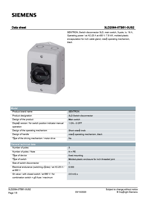
SENTRON 3LD 三极切换器手动操作说明书
3
3LD2064-0TB51-0US2 Page 3/9
03/10/2020
Subject to change without notice © Copyright Siemens
Hasp thickness / of the bracket locks / minimum Hasp thickness / of the bracket locks / maximum
2.5 kA2.s
100 000 50 1/h
690 V 6 kV 16 A
690 V
IP65 IP65
0.5 W
0.5 W
9A 16 A 16 A 16 A 16 A 16 A 16 A 16 A 16 A 16 A
16 A 16 A 16 A 16 A 16 A 20 A
3 kA
3LD2064-0TB51-0US2 Page 2/9
Protection class Protection class IP Protection class IP / on the front
Dissipation Power loss [W] ● for rated value of the current / at AC / in hot operating state / per pole ● per conductor / typical
03/10/2020
Subject to change without notice © Copyright Siemens
● at 690 V / for combination switch + gG fuse / maximum permissible Short-time withstand current (Icw) ● limited to 1 s / rated value ● at 690 V / limited to 1 s / rated value
INV-V1800系列超大型矩阵切换器使用说明书
INV-V1800系列超大型矩阵切换器使用说明书S e c u r i t y s y s t e m司标输入端矩阵类型输入口数量输出端输出口数量系列号INV-V X R X C X视频:V1800系列一、前言本手册是安装人员、调试人员和系统操作人员的指导文件,严格按照本手册规定的方法和要求实施,即可保证达到满意的应用效果。
技术指标:视频输入幅度1Vp-p(75Ω)视频输出幅度1Vp-p(75Ω)带宽:10MHz通道S/N:大于65dB通道隔离度:大于65dB通道串扰度:大于60dB通道增益:+1dB差分增益:3%差分相位:3°通讯方式:RS-485通讯速率:9600Bit/s、4800 Bit/s、2400 Bit/s、1200 Bit/s50 dB每一路输入端口具有共模抑制功能:通讯距离:大于7Km(无中间接力)通信口保护:瞬间大于3000V 强电220V供电:AC220V±10%,50H Z功耗:小于100W二、信号连接插座的位置及功能说明2.1 本机后面板各种信号接口功能说明POWER IN/BPOWER IN/ACOM 3RS 232COM 1COM 2IN1OUT1OUT2OUT3OUT4OUT5OUT6OUT7OUT8OUT1OUT2OUT3OUT4OUT5OUT6OUT7OUT8IN2IN3IN4IN5IN6IN10IN7IN11IN8IN12IN9IN19IN22IN16IN13IN20IN23IN17IN14IN21IN24IN18IN15IN37IN40IN46IN43IN31IN34IN28IN25IN38IN41IN47IN44IN32IN35IN29IN26IN39IN42IN48IN45IN33IN36IN30IN27INV-V1800后面板示意图POWER OUT/A POWER OUT/BAC220V1A配套电源箱后面板示意图IN1…IN48 输入信号连接插座 OUT1…OUT8 输出信号连接插座 RS-232 计算机汉字连接接口 COM1、COM2、COM3 本系统通信总线连接接口2.2 各种信号接口方法及要求 2.2.1 视频图像信号输入接口视频图像信号输入接口选用了标准25芯插座,每一对输入信号插座路数为1~16路。
FSR 4x1 HDMI 切换器用户手册说明书

DV-HSW4K-41HDMI 4x1 SwitcherBased on firmware 01.09244 Bergen Boulevard, Woodland Park, NJ 07424 ∙ Tel 973-785-4347 ∙FAX 973-785-3318 ∙ Web: 43097 LIT1565AUser ManualImportant Safety Instructions Contents are subject to change without notice WarningsTo reduce the risk of fire, electric shock or product damage:Table of ContentsImportant Safety Instructions (2)Overview (4)Features (4)Package Contents (5)Typical Application (5)Dimensions (6)DV-HSW4K-41 Front Panel (7)DV-HSW4K-41 Rear Panel (8)Hardware Installation (9)EDID Management (10)RS-232 Operation (11)RS-232 Serial Protocol (11)Request/Response Format (11)Field Separators (12)Command Request Syntax: (12)Acknowledging Receipt of Commands (13)Error Response (13)REQUEST LIST QUICK REFERENCE (13)Connection Request (14)Disconnect Request (14)HDCP Request (15)Model Request (16)Reconnect Request (16)Status Request (17)Version Request (18)Specifications (19)Limited Warranty (20)OverviewThe DV-HSW4K-41 is a 4 by 1 4K HDMI switcher, a perfect solution for managing multiple sources. It provides four inputs for direct connection of HDMI devices, which gives you a high performance connection between four sources and a display without signal loss.Simply pressing one button to selects the desired HDMI source for display on the HDTV. The front panel indicators show the currently selected source.It can be widely used in digital entertainment centers, control centers, conference rooms, schools and corporate training environments.The DV-HSW4K-41 is also an integral part of FSR's HuddleVU Collaboration SystemsFeatures∙ Easy installation∙Resolutions up to 4K@30Hz∙Both input/output port support HDMI cable up to 10m∙Four push buttons to select the input source∙HDMI 1.4 with 4K∙ HDCP compliant∙ EDID management∙12V DC Power Supply with locking connector includedPackage Contentsx HDMI Switcher DV-HSW4K-41 • 1• 1 x 12VDC Power Supply• 2 x Mounting Ears• 1 x 3.81mm Phoenix Connector (3 Pin) Typical ApplicationDimensions.30DV-HSW4K-41 Front PanelFront PanelID Name Description1 Power LED Lit when power is on2 Select Button Press to select HDMI IN 1 as input source3 Indicator LitHDMI IN 1 is selectedwhen4 Select Button Press to select HDMI IN 2 as input sourceHDMI IN 2 is selected5 Indicator Litwhen6 Select Button Press to select HDMI IN 3 as input sourcewhenHDMI IN 3 is selected7 Indicator Lit8 Select Button Press to select HDMI IN 4 as input sourceHDMI IN 4 is selected9 Indicator LitwhenDV-HSW4K-41 Rear PanelID Name Description 1 Power 12V 1A DC power input 2 HDMI IN 1 Connects to an HDMI source 3 HDMI IN 2 Connects to an HDMI source 4 HDMI IN 3 Connects to an HDMI source 5 HDMI IN 4 Connects to an HDMI source 6HDMI OUTConnects to an HDMI display 7 RS232RS232 control.For API commands, please refer to DV-HSW4K-41 RS-232 Serial Protocol8EDID DIP Switch Adjust EDID settingsHardware Installation1. Connect the HDMI input sources (such as Blu-Ray, game console, mediaserver etc.) to the input ports of the HDMI switcher using quality HDMI cables.Power off all equipment when connecting /extracting cables.2. Connect the HDMI display (LED/LCD display or projector) to the HDMIoutput port of the HDMI switcher.3. Connect the power supply to the HDMI switcher and power on all thedevices.4. To operate DV-HSW4K-41, use the front panel select button or remotecontrol handset.EDID ManagementThe HDMI Switcher features an EDID copy mode that can be used when the EDID’s do not meet the installation requirements.Note: The change doesn’t take effect until you restart the HDMI Switcher. Position Functions0 Automatically copy HDMI display's EDID to all HDMI Inputs, iffailed, the EDID of all HDMI inputs won’t change.1 4K2K 30Hz 2CH (Default)2 1280 x 800 60Hz 2CH3 1920 x 1080 60Hz 2CH4 1920 x 1200 60Hz 2CH5 1280 x 720 60Hz 2CH6 1024 x 768 60Hz 2CH7 800 x 600 60Hz 2CH10RS-232 OperationThe DV‐HSW4K‐41 switcher may be configured or queried via the RS232 serial connection.Baud Rate: 38,400bpsData bits: 8Stop bits: 1Parity: NoneFlow control: NoneComputer (DTE)DV-HSW4K-41Pin 2 Rx←TxPin 3 Tx→RxPin 5 Ground—GroundRS‐232 Serial ProtocolThe DV‐HSW4K‐41 switcher may be configured or queried via the RS‐232 serial connection.Request/Response FormatAll requests and responses will be entirely in ASCII. The requests can be in either upper or lower case.All requests will have three character command field followed by the data required for that specific request. All requests are terminated with a carriage return (0Dh), which will be referred to in this document as <cr>. All responses are terminated with a carriage return <cr> and a line feed (0Ah) which will be referred as <lf>.Field SeparatorsFields are separated by white space, that is any number of spaces or tabs as long as the entire command is less than 80 characters. A <cr> terminates the command. Below is an example describing a command.CON num <cr>So the actual message would look like this:CON 2<cr>Command Request Syntax:This document uses the following notation when describing the syntax of a command request:BOLD – identifies the commandlower case – identifies data to be entered which is described in the text following the syntax description" " ‐ entry defined within double quotes is to be entered exactly as shown< > ‐ entry defined within these brackets is required[ ] ‐ entry defined within these brackets is optional{ } ‐ entry defined within curly brackets must be entered at least once| ‐ a vertical bar denotes a logical choice of entry* ‐ an asterisk following either [ ] brackets or curly brackets { } above denotes that data within either brackets or curly brackets may be entered multiple times.Acknowledging Receipt of CommandsEach request sent to the DV‐HSW4K‐41 switcher will have by default two possible responses, an acknowledgement of a correct request or an error response. The acknowledge response will be:Ok<cr><lf>Error ResponseIt is inevitable that errors occur in the requests sent to the DV‐HSW4K‐41 switcher. If an invalid command is sent to the DV‐HSW4K‐41 switcher, the DV‐HSW4K‐41 switcher will respond with the message "ERR: unknown command". If an invalid parameter is sent to the DV‐HSW4K‐41 switcher, the DV‐HSW4K‐41 switcher will respond with the message "ERR:" followed by the valid syntax for the errored entry.Example:A connect request with an incorrect input number:CON 5<cr>The error response would be:ERR: CON 5<cr>REQUEST LIST QUICK REFERENCEREQUEST DESCRIPTIONCON Connection RequestDIS Disconnect RequestHDCP High Definition Content Protection Status RequestMOD Model RequestREC Reconnect RequestSTA Status RequestVER Request Version NumberConnection RequestThe connection request is used to connect one of the four available inputs to the output. A connection may be disconnected by using the DIS command (see later in document).CON input | "?" <cr>Syntax:CON <input | "?"><cr>Where:CON Connection request headerinput Input number in the range 1‐4"?" Request to return the currently selected input (the frontpanel LEDs reflect the currently selected input).(Note: A CON input command will override the disconnected output, ie via the DIS command. See below for description of DIS command.)Example:To connect input 2 to output, the connection request would look like this:CON 2<cr>To request the currently connected input, the connection request would looklike this: CON ?<cr>The response from the DV‐HSW4K‐41 switcher would be:CON 2<cr><lf>If a previously connected input were subsequently disconnected via the DIS command, then the CON ? command will return the currently selected input. Disconnect RequestThe disconnect request is used to disconnect (disable) the output of the switcher.DIS <cr>Syntax: DIS<cr>Where:DIS Disconnect request headerExample:To disconnect (disable) the output of the switcher, the user would send the following message:DIS<cr>HDCP RequestThe High‐bandwidth Definition Content Protection status request allows identification of the presence of HDCP on each of the available inputs. The format for the HDCP request is as follows:HDCP <cr>Syntax: HDCP<cr>Where:HDCP High Definition Content Protection request headerResponse: HDCP xxxxWhere:x is either 0 or 1, with 0 representing that HDCP is not present and 1 representing that HDCP is present.Example:To query the HDCP status of the unit the user would send the followingmessage: HDCP<cr>The response for the DV‐HSW4K‐41 switcher could be:HDCP 0111<cr><lf>That is, HDCP is not present on input 1 and HDCP is present on inputs 2‐4.Model RequestThe MOD Model request allows identification of the model number of the DV‐HSW4K‐41 switcher. The unit will return the current model identification, ie DV‐HSW4K‐41. The format for the model request is as follows:MOD <cr>Syntax: MOD<cr>Where:MOD Model request headerResponse: MOD model_numberWhere:model_number is DV‐HSW4K‐41 for this product.Example:To query the model number of the unit the user would send the followingmessage: MOD<cr>The response for the DV‐HSW4K‐41 switcher would be:MOD DV‐HSW4K‐41<cr><lf>Reconnect RequestThe REC request allows the user to reconnect the disconnected output to the currently selected input. Note that the input to be reconnected is as indicated by the input LED on the front panel. The command has no effect if an input is already connected to the output.REC <cr>Syntax: REC<cr>Where:REC Reconnect request headerExample:To reconnect the previously connected input 2 to output, the user would send the following message:REC<cr>Status RequestThe STA request returns the presence of signal on the respective inputs, 1 = signal present, 0 = no signal present.STA <cr>Syntax: STA<cr>Where:STA Status request headerExample:To query for the presence of signal on inputs 1‐4 the user would send the following message:STA<cr>If signal were present on input 1 and input 3, but not present on input 2 and input 4, then the response from the DV‐HSW4K‐41 switcher would be:STA 1010<cr><lf>If signal were not present on input 1 and input 3, but present on input 2 and input 4, then the response from the DV‐HSW4K‐41 switcher would be:STA 0101<cr><lf>Version RequestIn order to be able to identify the current firmware version populated in the unit, the user may request using the VER request. The format for the request will be as follows:VER <cr>Syntax: VER<cr>Where:VER Version Request headerResponse: VER DV‐HSW4K‐41 <XX.xx>Where:XX.xx XX = Major version number, xx = Minor version numberExample:VER<cr>To which the DV‐HSW4K‐41 switcher will respond:VER DV‐HSW4K‐41 01.09<cr>SpecificationsVideoInput 4 x HDMIOutput 1 x HDMIInput/ output Signal Type HDMI: HDMI 1.4 with HDCPInput/output Resolution Support HDMI: 480i,576i,480p,576p,720p@50,720p@60,1080p@24,1080i@25,1080i@30,1080p@30,1080p@50, 1080p@60, 4K x 2K@30Maximum Pixel Clock 297 MHzInput Video Signal 0.5~1.5 volts p-pVideo Impedance 100 ohmsGeneralPower Supply 12V 0.5A DCPower Consumption 4.1 Watts MaxControl Method Front Panel Buttons, RS232 controlOperating Temperature 32°F to 113°F(0°C to 45°C) 10% to 90%, non-condensingStorage Temperature -4°F to 140°F (-20°C to 70°C) 10% to 90%, non-condensingESD Protection Human-body Model:±4kV(Contact discharge)GeneralDimensions (L x W x H) 7.51" x 3.50" x 1.03"(191mm x 89mm x 26.1mm)Weight 1.00 lb (0.45kg.)Limited WarrantyThe DV-HSW4K-41 is warranted against failures due to defective parts or faulty workmanship for a period of three years after delivery to the original owner. During this period, FSR will make any necessary repairs or replace the unit without charge for parts or labor. Shipping charges to the factory or repair station must be prepaid by the owner, return-shipping charges (via UPS Ground) will be paid by FSR.This warranty applies only to the original owner and is not transferable. In addition, it does not apply to repairs done by other than the FSR factory or Authorized Repair Stations.This warranty shall be cancelable by FSR at its sole discretion if the unit has been subjected to physical abuse or has been modified in any way without written authorization from FSR. FSR’s liability under this warranty is limited to repair or replacement of the defective unit.FSR will not be responsible for incidental or consequential damages resulting from the use or misuse of its products. Some states do not allow the exclusion of incidental or consequential damages, so the above limitations may not apply to you. This warranty gives you specific legal rights, and you may also have other rights which vary from state to state.Warranty claims should be accompanied by a copy of the original purchase invoice showing the purchase date (if a Warranty Registration Card was mailed in at the time of purchase, this is not necessary). Before returning any equipment for repair, please read the important information on service below.SERVICEBefore returning any equipment for repair, please be sure that it is adequately packed and cushioned against damage in shipment, and that it is insured. We suggest that you save the original packaging and use it to ship the product for servicing. Also, please enclose a note giving your name, address, phone number and a description of the problem.NOTE: all equipment being returned for repair must have a Return authorization (RMA) Number. To get a RMA Number, please call the FSR Service Department (1-800-332-FSR1).Please display your RMA Number prominently on the front of all packages.CONTACT INFORMATION:FSRINC.244 Bergen Blvd.Woodland Park, NJ 07424Phone: (973) 785-4347Order Desk Fax: (973) 785-4207WebSite:。
Filax 2 超高速交流电转换器切换器用户操作手册说明书

DEUTSCHFilax 2Ultraschneller Wechselstrom-Transferschalter01 - 10/2021Diese Anleitung ist auch im HTML5-Format verfügbarInhaltsverzeichnis1. Allgemeine Sicherheitshinweise (1)2. Einführung (2)3. Systemdesign (3)4. Installation (8)5. Betrieb (10)6. Fehlersuche und Support (11)6.1. Falsche Schwellenwerte für Spannung oder Frequenz (11)6.2. Filax schaltet nicht auf die primäre Quelle um (11)6.3. Der Fehlerstromschutzschalter wird ausgelöst, wenn der Filax die Last überträgt (11)7. Gewährleistung (12)8. Technische Angaben (13)9. Anhang (14)9.1. Gehäuseabmessungen (14)9.2. Internes Schaltbild (14)WARNUNG•Im Gerät gibt es keine Teile, die der Verbraucher selbst warten könnte.•Nehmen Sie das vordere Paneel nicht ab und schalten Sie das Produkt nicht ein, wenn das vordere Paneel entfernt wurde.•Arbeiten an dem Gerät, gleich welcher Art, sollten ausschließlich von qualifizierten Fachkräften ausgeführt werden.•Lesen Sie vor der Installation des Geräts die Installationshinweise im Kapitel Installation [8] dieses Handbuchs.•Sorgen Sie dafür, dass das Gerät nur innerhalb der zulässigen Betriebsbedingungen genutzt wird.Der Filax ist ein ultraschneller Wechselstrom-Transferschalter. Der Schalter stellt sicher, dass empfindliche oder kritische Lasten, wie z. B. Computer oder unternehmenskritische Geräte, immer mit Strom versorgt werden, entweder von der primären Quelle oder von einer alternativen Quelle.Falls die primäre Quelle ausgefallen ist oder außerhalb der Spannungs- oder Frequenzspezifikation liegt, überträgt der Filax die Last von der primären Quelle auf eine alternative Quelle. Die Transferzeit beträgt weniger als 16 Millisekunden, so dass die Last immer mit Strom versorgt wird und unterbrechungsfrei weiterarbeitet.Sobald die primäre Quelle wiederhergestellt ist und mindestens 30 Sekunden lang innerhalb der Spezifikation liegt, überträgt der Filax die Last von der alternativen Quelle zurück auf die primäre Quelle. Die Transferzeit beträgt wiederum weniger als 16 Millisekunden, so dass die Last unterbrechungsfrei weiterläuft.Als primäre Quelle wird in der Regel das Stromnetz oder ein Generator verwendet, die alternative Quelle ist in der Regel ein Wechselrichter oder ein Wechselrichter/Ladegerät.Der Filax ist ein Transferschalter mit lückender (nicht brückender) Schaltfunktion. Er kann sowohl für den Einsatz in 50 Hz- als auch in 60 Hz-Systemen konfiguriert werden.Der Filax ist in 2 Modellen erhältlich:•Filax 2 Transferschalter CE 230 V / 50 Hz - 240 V / 60 Hz•Filax 2 Transferschalter CE 110 V / 50 Hz - 120 V / 60 HzModell 230 V / 50 Hz - 240 V / 60 Hz .......... Modell 110 V / 50 Hz - 120 V / 60 HzDer Filax eignet sich nicht für die Versorgung von Geräten mit hoher Leistung oder hoher Überspannung, wieElektromotoren, Waschmaschinen usw.Der Filax wird typischerweise in Notstromsystemen eingesetzt, damit kritische Lasten immer von einer Wechselstromquelle versorgt werden.Die Funktionsweise des Filax:Die kritische Last wird normalerweise von der primären Quelle versorgt. Wenn die primäre Quelle unterbrochen wird, wird die Last auf die alternative Quelle umgeschaltet. Sobald die primäre Quelle wiederhergestellt ist und 30 Sekunden lang stabil ist, wird die Last wieder auf die primäre Quelle umgeschaltet.In diesem Kapitel werden einige unterschiedliche Systemausführungen von Filax vorgestellt.Netz (oder Generator) mit Notstromversorgung durch Wechselrichter:Bei einem Stromausfall oder bei einem Ausfall des Generators (kein Brennstoff) schaltet der Filax die Last auf den Wechselrichter um. Sobald die Versorgung durch das Netz (oder den Generator) wiederhergestellt ist, schaltet der Filax die Last zurück zum Netz (oder Generator) um.Filax-System mit Notstromversorgung durch Wechselrichter zum Netz oder GeneratorNetz (oder Generator) mit Notstromversorgung durch Wechselrichter und Batterieladegerät:Falls ein Wechselrichter als alternative Quelle verwendet wird, muss die Batterie in einem guten Betriebszustand gehalten werden. Die Batterie sollte rechtzeitig und regelmäßig aufgeladen werden. Erweitern Sie dazu das System um ein Wechselstromladegerät oder ein Solarladegerät.Filax-System mit Notstromversorgung durch Wechselrichter und Wechselstromladegerät und/oder SolarladegerätNetz (oder Generator) mit Notstromversorgung durch Wechselrichter/Ladegerät:Es besteht auch die Möglichkeit, einen Wechselrichter/Ladegerät von Victron als Notstromversorgung (UPS) zu verwenden (ohne Filax). Der Wechselrichter bzw. das Ladegerät selbst bietet bereits eine Notstromfunktion (UPS).Sollte eine zusätzliche Redundanzstufe erforderlich sein, kann ein Filax zu einem System mit Wechselrichter/Ladegerät hinzugefügt werden. Dies dient als Ersatz für den Fall, dass ein Fehler des Wechselrichters/Ladegeräts auftritt. Außerdem kann der Wechselrichter/Ladegerät ausgetauscht werden, ohne dass die Versorgung der kritischen Last unterbrochen wird.Filax-System mit Notstromversorgung durch Wechselrichter/LadegerätNetz (oder Generator) mit Notstromversorgung durch zwei Wechselrichter/Ladegeräte:Bei Ausfall des Generators oder des Netzes versorgt der erste Wechselrichter/Ladegerät die Last. Bei einer Störung oder einem Ausfall des vorrangigen Wechselrichters/Ladegeräts überträgt der Filax die Last auf den zweiten Wechselrichter/Ladegerät. Im Vergleich zum vorherigen System wird dadurch eine zusätzliche Redundanzstufe hinzugefügt.Es gibt zwei Möglichkeiten, um ein solches System zu entwerfen. Entweder mit einer individuellen Batteriebank, je eine für jedes MultiPlus, oder mit einer einzigen Batteriebank für beide MultiPlus-Geräte.Filax-System mit zwei Wechselrichtern/Ladegeräten, die an einzelne Batteriebänke oder an eine einzelne Batteriebankangeschlossen sindErwägen Sie den Einsatz von IsolationsschalternEs ist eine bewährte Methode, vor und nach jedem Wechselrichter/Ladegerät Isolationsschalter einzubauen. Dadurch kann der Wechselrichter / das Ladegerät bei Wartungen oder im Falle eines Austauschs leicht isoliert und getrennt werden, ohne dass die Stromversorgung der kritischen Last unterbrochen wird.Filax-System mit zwei Wechselrichtern/Ladegeräten und IsolationsschalternErwägen Sie den Einsatz eines BatteriemonitorsEs ist wichtig, die Batterie zu überwachen. Wenn die Netz- oder Generatorversorgung nicht wiederhergestellt wird, entlädtder Wechselrichter oder das Wechselrichter/Ladegerät die Batterie. Schließlich sinkt die Batteriespannung so weit ab, dassder Wechselrichter oder das Wechselrichter/Ladegerät nicht mehr funktioniert. Mit einem Batteriemonitor können Sie den Ladezustand der Batterie überwachen oder bei niedriger Batteriespannung oder niedrigem Ladezustand eine Vorwarnung erhalten.Der Batteriemonitor BMV verfügt über ein Relais, das so programmiert werden kann, dass es in Abhängigkeit vom Ladezustand der Batterie oder der Batteriespannung ein- oder ausschaltet. Das Signal des Relais kann für Überwachungszwecke verwendet werden.Wenn eine Fernüberwachung erforderlich ist, kann der BMV oder der Batteriemonitor SmartShunt an ein Überwachungsgerät, wie den Globallink 520, oder ein GX-Gerät, wie den Cerbo GX, angeschlossen werden. Dadurch ist eine Fernüberwachung der Batteriespannung, des Ladezustands und der Alarme möglich (für ein GX-System siehe nächster Abschnitt).Filax-System mit BatterieüberwachungErwägen Sie den Einsatz einer vollständigen SystemüberwachungErweitern Sie Ihr System für eine vollständige Überwachung mit einem GX-Gerät, wie dem Cerbo GX. Das GX-Gerät überwacht nicht direkt den Filax, sondern die Wechselrichter/Ladegeräte, Batteriemonitore und/oder Solarladegeräte von Victron, die Teildes Filax-Systems sind. Die Systemüberwachung kann lokal, z. B. über WiFi, Ethernet, ein Display oder GX Modbus-TCP, oder aus der Ferne, z. B. über das Internet und das VRM-Portal, erfolgen.Filax-System mit vollständiger Lokal- und FernüberwachungPhysikalische Installation:•Installieren Sie den Filax in einer trockenen und gut belüfteten Umgebung.•Befestigen Sie den Filax über die 4 Löcher am Gehäuseboden.•Entfernen Sie zum Öffnen oder Schließen des Gehäuses die 4 Schrauben an der Oberseite des Gehäusedeckels. Elektrische InstallationSicherheitshinweise zur elektrischen Installation:•Achten Sie darauf, dass alle Wechselstromquellen ausgeschaltet sind oder während der Installationgetrennt wurden.•Die Verkabelung der Wechselstromeingänge und der Wechselstromausgänge muss mit Sicherungen oderStromkreisunterbrechern abgesichert werden, die für den verwendeten Leitungsquerschnitt geeignet sind.•Achten Sie darauf, dass sowohl die Haupt- als auch die alternativen Wechselstromeingänge gegenStromstärken von mehr als 16 A geschützt sind.•Es müssen externe Fehlerstromschutzschalter (RCD oder RCCB) in das elektrische System des Filaxintegriert werden.•Schließen Sie die primäre Wechselstromquelle an die PRIORITY (primär): L-, N- und PE-Anschlüsse an.•Schließen Sie die alternative Wechselstromquelle an die ALTERNATE (alternativ): L-, N- und PE-Anschlüsse an.•Achten Sie darauf, dass sowohl die Haupt- als auch die alternativen Wechselstromeingänge gegen Stromstärken von mehr als 16 A geschützt sind.•Schließen Sie die Wechselstromlast an die OUTPUT (ausgang): L-, N- und PE-Anschlüsse an.Elektrische VerbindungenKonfigurationKabelverbindungen:•Wenn die Wechselstromlast weniger als 850 W beträgt, entfernen Sie die Kabelverbindungen LINK+HIGH POWER: L und N.•Wenn die Wechselstromlast mehr als 850 W beträgt, lassen Sie die Drahtverbindungen LINK+HIGH POWER: L und N bestehen.Entfernen Sie beide Verbindungen, wenn die Last weniger als 850 W beträgtFrequenzüberbrückung:•Wenn die Installationsfrequenz 50 Hz beträgt, sollten Sie die Frequenzüberbrückung entfernen oder sie nur auf einen der Stifte stecken (das ist die Standardeinstellung).•Wenn die Installationsfrequenz 60 Hz beträgt, setzen Sie die Überbrückung auf beide Stifte.Überbrückung gesetzt = 60 HzÜberbrückung nicht gesetzt = 50 HzBeim ersten Einschalten:Der Filax verfügt nicht über einen Ein/Aus-Schalter. Sobald die primäre Quelle und/oder die alternative Quelle eingeschaltet wird, schaltet sich der Filax ein.Beim ersten Einschalten leuchtet die gelbe LED …Alternate Quelle“. Dies ist auch dann der Fall, wenn die primäre Quelle eingeschaltet wird. Nach 30 Sekunden Wartezeit erlischt die LED …Alternative Quelle“ und die LED …Primäre Quelle“ leuchtet auf. Die Lasten werden nun von der primären Quelle versorgt und der Filax ist betriebsbereit.Allgemeiner Betrieb:Die Last wird von der primären Quelle zur alternativen Quelle umgeschaltet, wenn:•Die Spannung der Hauptstromquelle unterschreitet den Schwellwert.•Die Frequenz der Hauptstromquelle unterschreitet den Niederfrequenz-Schwellwert bzw. sie überschreitet den Hochfrequenz-Schwellwert.Die Last wird von der alternativen Quelle zurück zur primären Quelle umgeschaltet, wenn:•Die primäre Quelle ist 30 Sekunden lang innerhalb der Grenzwerte für Spannungs- und Frequenzumkehrschaltung in Betrieb gewesen.Schlagen Sie in diesem Kapitel nach, wenn ein unerwartetes Verhalten auftritt oder wenn Sie einen Produktfehler vermuten.Bei der Fehlerbehebung und dem Support sollten Sie zunächst die in diesem Kapitel beschriebenen allgemeinen Probleme beachten.Sollte das Problem dadurch nicht behoben werden, wenden Sie sich an die Verkaufsstelle für technischen Support. Wenn die Verkaufsstelle nicht bekannt ist, informieren Sie sich auf der Support-Website von Victron Energy.6.1. Falsche Schwellenwerte für Spannung oder FrequenzPrüfen Sie, ob die Frequenzüberbrückung richtig eingestellt ist.Wenn die Überbrückung nicht für die richtige Frequenz eingestellt wurde, sind die Umschaltschwellenwerte für Spannung und Frequenz falsch. Die Spannungs- und Frequenzschwellenwerte für jede Frequenzeinstellung finden Sie im Kapitel Technische Angaben [13].6.2. Filax schaltet nicht auf die primäre Quelle umWenn die rote LED für Prioritätsfehler leuchtet, bedeutet dies, dass der Filax nicht mit der primären Wechselstromquelle verbunden ist.•Prüfen Sie, ob die primäre Versorgung verfügbar ist und innerhalb der Spannungs- und Frequenzschwellenwerte liegt.•Überprüfen Sie die Verkabelung der primären Quelle, Stromkreisunterbrecher, Fehlerstromschutzschalter und Sicherungen. Beachten Sie, dass wenn die rote LED für Prioritätsfehler nicht leuchtet, die primäre Quelle verfügbar ist und der Filax sich nach 30 Sekunden mit ihr verbinden sollte.6.3. Der Fehlerstromschutzschalter wird ausgelöst, wenn der Filax die LastüberträgtDer Filax ist ein zweipoliger Transferschalter, der ohne Unterbrechung schaltet. Für den korrekten Betrieb des Fehlerstromschutzschalters sollten beide Eingänge als einzelne Stromquellen betrachtet werden. Aus diesem Grund müssen beide Eingangsquellen eine Nullleiterverbindung haben. Die Nullleiter dürfen nicht zwischen den Eingängen oder zwischen einem Eingang und dem Ausgang miteinander verbunden werden.Für dieses Produkt gilt eine Gewährleistung von 5 Jahren. Diese Gewährleistung deckt Materialmängel und Verarbeitungsfehler an diesem Produkt ab. Sie gilt für fünf Jahre gerechnet ab dem ursprünglichen Kaufdatum dieses Produktes. Um die Garantiein Anspruch zu nehmen, muss der Kunde dann das Produkt zusammen mit der Quittung dorthin zurückbringen, wo er es gekauft hat. Diese beschränkte Gewährleistung gilt nicht für Beschädigungen, Abnutzung oder Fehlfunktionen durch: Umbau, Veränderungen, unsachgemäße oder zweckentfremdete Nutzung, Verletzung der Sorgfalt, wenn das Gerät zu viel Feuchtigkeit oder Feuer ausgesetzt wurde; wenn es nicht ordnungsgemäß verpackt wurde, bei Blitzschlag, Stromschwankungen oder andere Natureinflüsse. Diese eingeschränkte Gewährleistung deckt keine Beschädigungen, Abnutzungen oder Fehlfunktionen ab, die aufgrund von Reparaturen durch eine Person verursacht werden, die nicht von Victron Energy zur Durchführung solcher Reparaturen befugt ist. Bei Nichtbeachtung der Hinweise in dieser Anleitung erlischt der Gewährleistungsanspruch. Victron Energy übernimmt keine Haftung für Folgeschäden, die sich aus der Nutzung dieses Produktes herleiten. Die maximale Haftung durch Victron Energy im Rahmen dieser beschränkten Gewährleistung übersteigt nicht den tatsächlichen Einkaufspreis dieses Produktes.9.1. Gehäuseabmessungen20025523R5(4x)75 2375.2(4x)755050100176120SDFI0000000Filax 2 Transfer Switch CE 230V/50Hz-240V/60Hz SDFI0000110Filax 2 Transfer Switch CE 110V/50Hz-120V/60HzDimension Drawing - Filax 2Dimensions in mm9.2. Internes Schaltbild。
音频切换器使用说明书

凯联音频切换器使用说明凯联音频切换器包括4路音频输入,2路音频输出(预监和节目),可以通过通讯端口自动控制切换,提供两个RS-232接口可与两台计算机相连并同时使用。
凯联切换器采用1U 标准上架机箱,使用灵活方便,可广泛应用于广播电台、电视台、电教中心等各类广电系统。
【技术指标】●供电电压交流220V±(220*10%)V 50HZ●工作温度范围 5°C-30°C●极限工作温度范围 -5°C-40°C【装置结构】前置面板:①②③④⑤图1-前面板①电源开关:红灯亮机器通电工作②OUT1-OUT4选择主输出音频通道,红灯亮为当前所选通道,支持自动切换功能③PREVIEW5-PREVIEW8选择预监输出音频通道,红灯亮为当前所选通道④A/M选择主输出手动/自动切换模式,红灯亮为自动切换⑤调整主输出的音频音量后置面板:①②③④⑤图2-后面板①四路音频输入,从左到右分别为1、2、3、4,其中第1路支持掉电直通。
②OUT:主输出③MON:预监输出④COM1、COM2:控制口,直接连接到计算机的COM口。
⑤220V电源插1【操作指南】本机控制方式有手动及自动,其中主输出及预监输出均支持手动切换方式;手动控制电路采用自复式按键,电路互锁,带回灯指示。
控制码经锁存器锁存后送音频切换器。
与计算机串口连接,可控制自动切换,自动切换方式只有主输出支持。
在计算机控制时,首先将前面板控制按键打到自动位置,计算机为COM口输出,可以直接RS232与本机通讯。
1.将音频输入信号接入后面板输入口2.从主输出口-OUT输出到播出设备,预监口-MON输出到监听器3.连接COM1/COM2口到计算机的COM口4.连接电源,开机5.前面板A/M-手动/自动转换:A-自动(灯亮),M-手动注:插拔输入输出电缆及COM口线时,请先关闭主机电源。
Schmersal SE-100C安全切换器说明书
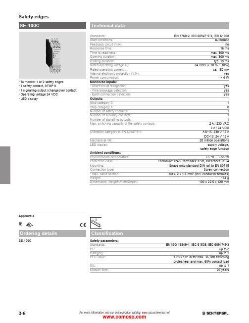
3-6For more information, see our online product catalog: • T o monitor 1 or 2 safety edges • 1 safety contact, STOP 0• 1 signalling output (changeover contact)• O perating voltage 24 VDC • L ED displayApprovalsHSE-100CStandards: EN 1760-2, IEC 60947-5-3, IEC 61508Start conditions: automatic Feedback circuit (Y/N): no Response time: 16 ms Time to readiness: max. 300 ms Opening duration: max. 300 ms Closing duration: typ. 15 ms Rated operating voltage U e : 24 VDC (+ 20 % / -10%)Rated operating current I e : ca. 150 mA Internal electronic protection (Y/N): yes Power consumption: < 4 WMonitored inputs: - Short-circuit recognition: yes - Wire breakage detection: yes - Earth connection detection: yes Outputs:Stop category 0: 1Stop category 1: 0Number of safety contacts: 1Number of auxiliary contacts: 1Number of signalling outputs: 1Max. switching capacity of the safety contacts: 2 A / 230 VAC2 A / 24 VDCUtilization category to EN 60947-5-1: AC-15: 230 V / 2 ADC-13: 24 V / 2 AMechanical life: 20 million operations LED display: supply voltage,safety edge functionAmbient conditions:Environmental temperature: +5 °C … +55 °C Protection class: Enclosure: IP40, Terminals: IP20, Clearance: IP54Mounting: Snaps onto standard DIN rail to EN 60715Connection type: Screw connection - max. cable section: max. 2 x 1.5 mm² (incl. conductor ferrules)Weight: 164 g Dimensions (Height/Width/Depth):100 x 22.5 x 120 mmSafety parameters: Standards: EN ISO 13849-1; IEC 61508; IEC 60947-5-3PL:up to c Category: up to 1PFH value: 1.73 x 10⁻⁶/h for max. 36,500 switching cycles/year and max. 60% contact loadSIL:up to 1Mission time:20 years3-7For more information, see our online product catalog: • M onitoring the safety edges SE 40 / SE 70 with a safety monitoring unit SE-100C for PL c and category 1.• I f only one safety edges SE 40 / SE 70 is connected, the terminals S12-S22 must be bridged.• T he manual reset function, if required, must be realized in the machine control. Both re-initialization and auto-reset must comply with the requirements of EN 1760-2 (diagram A2, A3).• The wiring diagram is shown for the de-energized condition.• T he overall machine safety depends on the professional mounting and installation of thesafety monitoring module and the signal transmitter, as well as on the correct and professional e lectrical connection of the components.• I f there it any risk whatsoever, the machine may not be restarted.• I nductive loads (e.g. contactors, relays, etc.) are to be suppressed by means of a suitable circuit.。
DH1000A-F副机切换器说明书
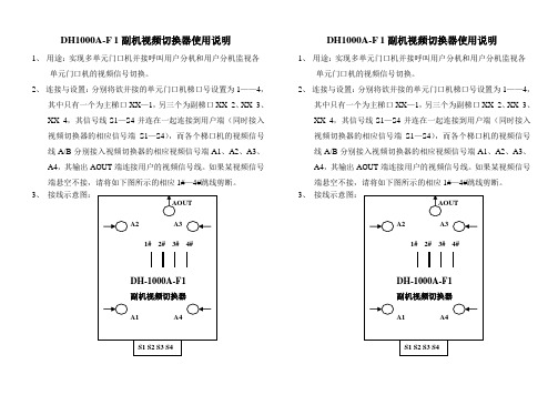
DH1000A-F 1副机视频切换器使用说明
1、用途:实现多单元门口机并接呼叫用户分机和用户分机监视各
单元门口机的视频信号切换。
2、连接与设置:分别将欲并接的单元门口机梯口号设置为1——4,
其中只有一个为主梯口XX—1,另三个为副梯口XX_2、XX_3、XX_4,其信号线S1—S4并连在一起连接到用户端(同时接入视频切换器的相应信号端S1—S4),而各个梯口机的视频信号线A/B分别接入视频切换器的相应视频信号端A1、A2、A3、A4,其输出AOUT端连接用户的视频信号线。
如果某视频信号端悬空不接,请将如下图所示的相应1#—4#跳线剪断。
3、接线示意图:
DH1000A-F 1副机视频切换器使用说明
1、用途:实现多单元门口机并接呼叫用户分机和用户分机监视各
单元门口机的视频信号切换。
2、连接与设置:分别将欲并接的单元门口机梯口号设置为1——4,
其中只有一个为主梯口XX—1,另三个为副梯口XX_2、XX_3、XX_4,其信号线S1—S4并连在一起连接到用户端(同时接入视频切换器的相应信号端S1—S4),而各个梯口机的视频信号线A/B分别接入视频切换器的相应视频信号端A1、A2、A3、A4,其输出AOUT端连接用户的视频信号线。
如果某视频信号端悬空不接,请将如下图所示的相应1#—4#跳线剪断。
3、接线示意图:。
INV-V32系列视频矩阵切换器

INV-V32系列视频矩阵切换器使用说明书S e c u r i t y s y s t e m版本:NO.6INV-V32系列视频矩阵切换器使用说明书一、概述:INV-V32系列视频矩阵切换器是中等规模的矩阵切换器,该机是由微处理器控制,主芯片为专用视频矩阵芯片。
最大32路视频输入,8路视频输出。
与INV-K5005、INV-K5009或多媒体电脑相联,组成一个完整的图像监控控制系统;配上INV-A32系列音频矩阵,可实现音频同步切换;配上INV-M84系列报警联动控制器,可实现报警联动切换。
二、主要功能:1.可任意切换:通过操作键盘的控制可实现任意一个输入可切换到任意一个输出上。
2.时序切换功能:通过操作键盘的控制定时切换图像到输出通道上。
3.切换时间间隔:1~60秒可调。
4.报警联动功能:配合报警联动控制器,一旦接收到报警信号,通过后面板的报警联动输出端子,输出一个开关量信号,用以启动录像机进入录像状态;同时有二个辅助开关量输出,用于联动其他设备。
5.屏幕菜单功能,使用户对该机的操作更为直观和简便。
注:上述功能的具体操作方法见INV-K5005、INV-K5009或多媒体电脑使用说明书。
三、技术参数:1.视频输入信号幅度:1Vpp(75Ω)2.视频输出信号幅度:1Vpp(75Ω)3.通讯接口方式:RS-4854.通讯速率:9600bit/s5.通讯线联接:总线制,用一根带屏蔽双绞线与通讯总线相连6.图像带宽:10MB7.通道隔离度:42dB8.供电电源:AC220V±10%50Hz9.整机功耗:30W10.工作环境温度:-10℃~+50℃。
四、接线方法:1.连接方法:►将32只摄像机的视频输出用75Ω同轴电缆分别接入1...32号视频输入端。
►用75Ω同轴电缆连接视频输出到对应的监示器上。
►用电线连接本机的通讯接口至通讯总线上。
通讯线应是两根为红、绿色的线,连接通讯线时应注意通讯总线的正负极性(即红线与红线相连,绿线与绿线相连)。
ANT-RGB系列矩阵切换器使用说明书
使用红外线遥控器(可选)
安装方式 通过面板上的固定孔固定在19”机架上
外形尺寸
16x16:5U(482mm×222mm×300mm) 32x32:10U(482mm×444mm×300mm)
①、除了 RGBHV 以外,大多数信号不采用带 RGBHV 传输电缆,这时候需要自备转换接头。
第 6 页 共 28 页
通讯接口 1200 ~ 115200 bps(缺省 9600 bps) 8 位数据/1 位停止位/无校验位
电源 220V(±20%)/50Hz
第 5 页 共 28 页
ANT-RGB 系列矩阵切换器使用说明书
功耗 55W
其它
切换时间 200ns
状态记忆 可保存 16 种工作状态
使用前面板按键
控制方式 通过 RS-232 接口远程控制
输入信号分别切换到任何一个或多个输出通道。该设备具有断电现场保护功能,能保存设备关机前的工作 状态,具备与计算机联机使用的 RS-232 通讯接口,并提供通讯协议和演示程序,方便联机使用。表 A 列 出了现在本系列所包含的七款矩阵切换器。
本产品广泛应用于需要切换和选择 RGBHV 信号的各类场合,如:广播电视、大屏幕投影电视、电化教 育、电视电话会议、多媒体会议室等。
三、 外观说明
1、 矩阵切换器的前面板 16 x 16
ANT- RGB 系列矩阵切换器使用说明书
①
②③④⑤
⑥
32 x 32
①
②③④ ⑤ ⑧ ⑨ ⑩
第 7 页 共 28 页
ANT-RGB 系列矩阵切换器使用说明书
① 液晶显示模块。 ② 电源指示灯。 ③ 通讯指示灯,有按键按下时,闪烁一下,接收到有效的串口数据包或遥控器数据后,会闪烁两下。 ④ 红外线信号接收器。 ⑤ 功能按键,上面一个是确定键,下面一个是取消键。 ⑥ 端口选择按键,上面一排是输入按键,下面一排是输出按键。 ⑦ 音/视频选择键,哪个按键上的指示灯点亮,表明切换哪种信号。 ⑧ 数字输入键,在切换和其它设置操作的时候输入数字。 ⑨ 切换控制键,左边一个是“I->O”键,右边一个是“OUT”键。 ⑩ 保存/调出预案,左边是保存键,右边是调出键。
轩氏KVM切换器使用说明书
KVM切换器使用说明书唐山轩氏科技有限公司Tangshan XuanShi Electronic Co.,Ltd轩氏KVM切换器功能特点:1、支持单独或同事开机、关机2、切换速度快、切换无延迟3、内置看门狗,永远不死机4、支持面板按键、键盘、遥控器三种方式切换5、数码管显示、直观、大方6、不用转接头,直接接入就能使用7、支持串口控制单台计算机8、支持单次、循环轮显方式9、支持检测电脑是否在线10、支持鼠标绝对定位和相对定位两种工作方式11、支持热键设置、可以自由设置切换按键12、支持同步功能(KVM同步器功能开启方法:【Scroll lock】+【Scroll lock】+ 顿号)13、同步功能:【scrolllock】+【scrolllock】+顿号功能简介:一、VGA切换a、键盘切换:1、热键切换:【scrolllock】+【scrolllock】+小键盘的1-4,进行切换;同时面板对应显示01-042、轮显切换:【scrolllock】+【scrolllock】+s,自动轮显;按空格键停止轮显。
3、单次轮显切换:连续按下两次win键,轮显一次。
如:当前显示03,连续两次按键win 将显示:03-04-05-06-07-08-01-02一次b、kvm面板按键切换1、单键切换:按下kvm面板上的按键进行切换,同时面板对应显示01-042、轮显切换:(1)4口kvm先按下kvm面板上的F1键,再按下面板上的1键,自动轮显;(2)4口kvm第一次按下面板上的F1键,自动轮显;再次按下面板上的F1键,停止轮显c、遥控器切换:1、单键切换:按遥控器上对应的按键实现1-4号机的切换,同时面板对应显示01-042、轮显切换:(1)4口KVM先按遥控器的菜单键,再按1键,自动轮显;按静音键,停止轮显。
(2)4口KVM第一次按下菜单键,自动轮显;再次按下菜单键,停止轮显。
注:1、如果面板显示-01--04,表示对应某台计算机只接了VGA线,没接USB线。
- 1、下载文档前请自行甄别文档内容的完整性,平台不提供额外的编辑、内容补充、找答案等附加服务。
- 2、"仅部分预览"的文档,不可在线预览部分如存在完整性等问题,可反馈申请退款(可完整预览的文档不适用该条件!)。
- 3、如文档侵犯您的权益,请联系客服反馈,我们会尽快为您处理(人工客服工作时间:9:00-18:30)。
科迪矩阵控制软件使用说明
第一章软件安装
本软件为绿色软件,将该科迪矩阵控制软件目录复制到硬盘上即可。
复制完成后,运行RWMP286.exe。
默认的用户名为:aaa,密码:123
第二章软件使用
运行RWMP286.exe后,会出现如下界面:
(以下图片仅供参考,软件版本以应用软件为准)
A切换画面简介:
上图中,每一个彩色圆饼处所处的交叉点位置对应一路信号的输入输出关系。
右方为输出信号(即矩阵的目的端口),上方为输入数(即矩阵的源信号端口)。
例如,上图表示输入1切换至输出1,输入2切换至输出2,......,输入16切换至输出16。
当鼠标在屏幕上移动时,对应的输入和输出路数颜色会变化,以示区别,上图中鼠标停留在输入16(in16)和输出14(out14)的位置上。
圆饼被分隔成几部分,就表示矩阵有多少层,上图中圆饼有红色、蓝色两部分,故有视频、音频两层;当只点亮其中一层时,就单独切换该层,若全部点亮,则为多层同时切换。
按钮:状态刷新按钮,点击该按钮,矩阵的所有状态将刷新一遍。
当矩阵规模较大时,刷新时间会较长(几秒至几十秒不等)。
按钮:通过点击该按钮,可以放大或缩小的大小和显示的圆饼个数。
按钮:在预置后,‘切换’为按照预置进行切换;‘取消’为取消预置键。
保存预置设置功能:。
按“增加”键,进行预置,
单击鼠标左键,如上图所示,预置切换路数,按“Done”即可按照自己定义的“Name”一栏的名称进行保存。
调用时,单击下拉菜单中选择已经预置的内容,所预置的内容通过“编辑”可以进行修改,并保存。
显示与矩阵之间的通讯数据,供专业人士参考。
B快速使用入门:
1、查询矩阵状态:
1)单路查询:鼠标左键单击屏幕右侧的输出按键,圆饼的位置就是所对应的输入路数。
2)多路查询:鼠标左键单击状态刷新按钮,所有路的状态将刷新一遍。
2、切换路数:
1)单路切换:鼠标左键双击输入、输出的交叉点位置,既将所对应的输入路切换到所对应的输出路。
鼠标左键单击输入、输出的交叉点位置,既将所对应的输入路预置到所
对应的输出路,之后按‘切换’键,即实现切换。
2)多路切换:鼠标左键单击多处输入、输出的交叉点位置,预置多路,之后按‘切换’键,即实现切换。
预置多路
点击‘切换’切换
3、锁定、解锁:
单击鼠标右键,选项中有“锁定”选项,单击它,即将该输出路数锁定。
锁定后,该输出路数不可切换。
若想切换必须先单击右键对该路进行“解锁”操作。
锁定前
锁定后
4、下拉菜单中的其他选项:
1)读矩阵配置:读取矩阵的设置并执行“刷新”操作。
2)打开:设置预置。
3)关闭:取消预置。
4)配置:设定一些软件配置,单击后出现系统设置界面。
通讯:通讯串口号选择;
速率:通讯的传输速率(不可更改);
层:矩阵的层数;(注:矩阵的层数和规模在软件启动后自动获取,一般不需要设置)输入:输入的最大路数;
输出:输出的最大路数;
使用TCP/IP通讯:
使用网口通讯时,请点击“使用TCP/IP通讯”,软件的默认IP地址为192.168.0.247(如上图),请根据使用环境或咨询网络管理员设定合理的IP地址,(也可以通过串口助手向设备发送*RI#命令读取设备的IP地址)端口选择处输入22,23,24中的一个,不支持其他的端口号。
注意:此处输入的IP地址必须与矩阵主机的IP地址一致,否则无法连通!
使用串口调试助手可以通过串口修改矩阵的IP地址,修改完成后必须对矩阵主机断电并重新上电,IP地址更改才能生效(具体串口指令请参考通讯协议的“读写IP地址指令”)。
5、定时切换的说明
选择定时切换后将出现如下界面
下面通过定时切换设置举例进行说明 (1)编辑定时切换列表区
通过对任务的插入、删除、清除的操作,编辑将要定制的任务列表。
每一列均代表在特定时间某一输入端口切换至某一输出端口。
比如,列表第一行表明,“循环1234567”周一至周日,每天的10:46:43,进行将输入端口1切换至输出端口1的操作。
在当前选中行之前插入任务
在当前选中行之后插入任务 删除当前选中行
删除所有行
(2)对单个任务的编辑 ①对切换内容的操作
注意:编辑操作必须先选中列表中的某一任务,否则操作无效。
对光标选中当前所在行进行操作
注意:
操作时必须选中某一行
通过对输入、输出的下拉选单进行指定路数的切换设置换
通过对层中的V 、A 前面的圆形标记的双击操作进行层的增减,必须至少有一层前面的圆形图标存在,代表切换某层或某几层
②对切换循环周期中日期的操作
通过对循环的下拉菜单选中已经预置好的循环种类,对应显示在右侧循环对话框中注意:
操作时必须选中某一行
对光标选中当前所在行进行操作
双击红色旗帜,
天作为预置切换的循环周期,
与左侧循环下拉菜单中不同,
对话框内显示为准进行周期切换
③对切换循环周期中时间的操作
对当前选中行进行的修改时间按操作,将显
示在上方任务列表中。
注意: 操作时必须选中某一行
对光标选中当前所在行进行操作 秒清
0操作即将该选中任务的秒清0。
简化
设定操作。
此操作同样在选定的任务中进行
(3)任务的保存与加载
将修改后的任务列表保存在指定目录
也可导入已有的任务列表添加到当前列表中。
(4)任务的启动
注意,所设置的任务,必须在设置页面中启动,并在总页面中勾选Task ,方可启动定时任务。
没有这两部分的启动,将无法进行定时的切换操作。
设置完成后,可保存任务列表,退出当前对话框。
通过对某一任务的双击操作,可以改变某一单个
任务的使能状态
也可通过“全部启动”或“全部停止”进行总的
使能和禁止的操作。
注意:启动定时切换,需要在设置中将任务列表中任务启动后
,在总 界面中,必须勾选Task 复选框
,此时右下角有红色闪动上下方向的箭头
,此时表明已启动定时切换。
6:关于输入输出信号名称的修改
如果需要修改软件上显示的输入输出端口名称,请打开title.txt 文件,编辑文件中对应的路数即可,注意要与默认的格式一致。
可修改名称。