惠普Procurve以太网交换机配置指南-Version-1.0
hp procurve 6120 系列刀片交换机常见技术问题与解答

HP ProCurve常见问题HP ProCurve 6120系列刀片交换机的硬件与软件架构是什么?硬件架构基于惠普虚拟连接模块。
HP ProCurve 6120G/XG刀片交换机硬件可借助HP 1/10Gb-F虚拟连接以太网模块充分发挥自身潜能;HP ProCurve 6120XG刀片交换机硬件以惠普虚拟连接Flex-10万兆以太网模块为基础彰显巨大优势。
软件架构基于HP ProCurve交换软件。
在第一个版本中,该功能可借助企业级管理、安全和配置,提供强大的第2层交换能力。
其他功能目前正在规划中。
这些交换机是否享有HP ProCurve终身保修?享有。
刀片交换机间有一个内置链路。
该内置链路如何在6120G/XG和6120XG刀片交换机上发挥作用?这些交叉链路端口可用于连接两台相邻刀片交换机间的数据层,构建冗余配置,以便一台刀片交换机的上行链路出现故障时,刀片服务器仍可通过交叉链路中的另一台刀片交换机实现通信。
6120G/XG刀片交换机间有一个内置万兆交叉链路。
该链路不包括外置端口,可以通过默认设置禁用,并通过CLI命令启用。
插入收发器不会影响内置交叉链路,但必须先运行CLI命令。
6120XG刀片交换机配有2个内置交叉链路,但需要与2个外置SFP+端口共享。
通过CLI启用内置交叉链路后,外置端口无法使用。
再次强调,插入或移除收发器不会影响内置交叉链路。
注意,可以在6120XG刀片交换机的2个交叉链路端口上,静态激活链路汇聚控制协议(LACP),使其可以发挥单一实体的作用。
生成树协议可以通过刀片交换机上的默认设置激活,因此即使启用交叉链路,也不会产生回路。
6120XG刀片交换机拥有双功能定制交叉链路端口,但收发器处于热插拔状态时,可以通过默认设置关闭这些端口。
带外管理(OOBM)端口有什么作用?如何利用该端口配置刀片交换机?可以借助HP BladeSystem c-Class服务器机箱上的onboard administrator (OA)模块,通过带外管理端口配置刀片交换机。
HP procurv交换机配置手册2524_lacp

HP ProCurve Switch 2524(config)# hostname Switch_A
2500 Switches. The first command in the sequence of CLI commands given below will first reset a
Series 2500 Switch back to its factory default settings. We recommend saving your current
configuration if necessary. Otherwise, skip the first command.
WARNING:
NOTES:
1. By default, LACP is enabled (all ports are set to LACP passive) on the Series 2500 Switches. For a dynamic LACP trunk to form, at least one end of the link must be LACP active. 2. The Series 2500 Switches support one trunk group of up to four ports, and the ports need not be consecutive or contiguous on the switch. 3. Dynamic LACP trunks are always created in the DEFAULT_VLAN of Series 2500 Switches. That is because the LACP protocol does not send VLAN information, so the switches have no way to know what VLAN or VLANs to put the trunk into. 4. There is no limit, besides the number of physical ports available on the switch, on the number of "standby" ports in an LACP trunk group. 5. If STP and/or IGMP is enabled in the switch, a dynamic LACP trunk operates only with the default settings for these features and does not appear in the port listings for these features. 6. Port security does not operate on a trunk group. 7. The configuration examples below were created on software version F.01.07.
以太网交换机怎么设置

以太网交换机怎么设置以太网交换机怎么设置在计算机上运行Telnet客户端程序(这个程序在Windows系统中与UNIX、Linux系统中都有,而且用法基本是是兼容的,特别是在Windows2000系统中的Telnet程序),并登录至远程交换机。
如果我们前面已经设置交换机的IP地址为:61.159.62.182。
一、交换机怎么用组网设备准备另外,另一必不可少的设备就是交换机,计算机之间的相互通信全靠它作中转设备;还有就是每台计算机需要安装一块网卡负责接收数据,以及急讣父荽涞耐ǖ馈撸琌K,基本上就这些东西了。
而如果你只有两台计算机,大可不必如此麻烦,直接在两台计算机里各安装一块网卡,再用网线连接起来就OK了。
1、交换机怎么用:宽带路由器宽带路由器有两个作用,一个作用是连通不同的网络,另一个作用是选择信息传送的线路,它是共享宽带连接的最佳解决方案。
并以易使用、易管理、零维护的优点成为Internet共享接入的首选设备。
选择路由器和选择电脑是一个道理,首先要看硬件。
硬件是路由器运行的基础,硬件型号好,质量高,路由器不但功能稳定,而且可进行功能的扩展。
比如接入计算机数量,一般中上档次的接入路由器可支持100台PC机,且除了IP共享和路由功能外还具有防火墙、时间管理、DMZ等功能;再比如大容量的内存和闪存,都可为路由器提供强劲的处理能力。
目前市面上,这类产品的品牌不少,大家可向周围朋友打听打听,什么牌子在当地口碑不错。
比较常见的有:友讯(D-LINK)、TP-LINK、艾泰科技、思科、3Com、华为3Com等。
2、交换机怎么选购交换机,这个集线器的后续产品,无论是在速度及具备功能上,都是前者所不能比拟的。
其主要功能就是实现多台计算机的互连互通,相当于文前提到的“中间人”的作用。
而在如今家用交换机市场,因为不同品牌、不同端口数的交换机价格差距很大。
所以在选购时,应该根据自己的实际情况来选择,比如选择的'组网方式、承受的价格、品牌、喜欢的交换机外形等,另外还必须注意交换机的各项性能指标,比如接口数量等,一般说来,5口和8口的交换机是首选。
ProCurve Switch 2510 系列交换机

• ProCurve Auto-MDIX:自动适应所有 10/100 和 10/100/1000 铜端口上的直连或交叉电缆
灵活性和高可用性
• 多种用户身份验证方法:
-IEEE 802.1X:符合行业标准的用户身份验证方 法,结合使用客户端上的 IEEE 802.1X 申请者
• IEEE 802.3ad 链 路 汇 聚 控 制 协 议 (LACP)和
IEEE 802.1w 提供传统支持
第 2 层交换
• VLAN 支持和标记:支持高达 64 个基于端口的 VLAN 和 IEEE 802.1Q VLAN 动态控制标记,以在 工作组间提供安全性
• GARP VLAN 注册协议:可使 VLAN 进行自动获悉 和动态分配
• 巨型包支持(仅 2510G):支持高达 9216 字节的帧, 从而提高海量数据传输的性能
• TACACS+:使用密码验证服务器简化交换机安全 络问题,并通知管理员
性管理
• 双闪存映象:可提供独立的主、辅操作系统文件,
融合性
以便在升级过程中进行备份
• IP 组播(数据驱动的 IGMPv3):自动防止 IP 组播流 • 软件升级:从网上免费下载
量的泛滥(仅 2510-24)
灵活性
服务质量(QoS)
• RMON:为统计信息、历史记录、报警和事件提 供高级监测及报告功能
3
ProCurve Switch 2510 系列交换机
服务
附件
• 3 年 4 小时现场硬件服务,13 x 5 覆盖(U4683E) ProCurve Gigabit-SX-LC Mini-GBIC (J4858C)
• 3 年 4 小时现场硬件服务,全天候覆盖(U4835E) ProCurve Gigabit-LX-LC Mini-GBIC (J4859C)
ProCurve交换机配置手册

第一章交换机的初始配置1.1使用CONSOLE口进行交换机的配置1.超级终端配置如下:开始-附件-通讯-超级终端,在COM口属性的窗口中选择还原默认值。
端口配置参数值每秒位数(B):9600数据位(D):8奇偶校验(P):无停止位(S): 1数据流控制(F):无2.配置好超级终端后,回车登陆。
H P系列产品默认需要认证,才能进行管理配置,默认的用户名为空,口令为空。
图:此时将进入登陆模式,登陆模式的符号是一个大于号“>”,在此模式下可以实现基本的状态查看功能,通过问号“?”可以查看此状态下所有可操作的命令.HP系列产品所有模式下(登陆模式,管理模式和配置模式)均有这种帮助功能,同时在输入命令时,可以通过<tab>键进行命令补足.登陆模式:以“>”开头,仅仅能够进行一些基本状态查看管理模式:以“#”开头,能够进行所有状态信息的查看,同一时刻允许有多个管理员处在此模式下。
从登陆模式进入管理模式的命令:en able(可简写为e n),通过enab le口令认证后,即可进入管理模式。
配置模式:以“(con fig)”开头,能够对设备进行配置和管理,同一时刻仅仅允许一个管理人员处在配置模式下。
此模式下可以同时具有管理模式和登陆模式的功能。
从管理模式进入配置模式的命令为:conf igur e,即可进入配置模式。
从高级模式退出到低级模式的命令为exi t或disa b le。
3.基本命令1)、查看操作系统版本及硬件信息命令:s h o w v er sion作用:查看当前系统版本和状态信息系统当前版本:test_5304x l#s h o w v ers i onIm age sta mp:/s w/c ode/buil d/al pm o(m35)A ug2200511:27:11E.10.044015B oot Im age:Pr i m ar y系统主机名:系统C P U类型:系统内存容量:系统启动时间:系统当前时间:系统端口类型:系统序列号:系统当前能实现的功能:2)、配置主机名:命令:hostname<n ame-st ring>:其中主机名长度最长为64字节实例:例如需要配置设备的名称为B lue,则命令如下。
惠普企业级计算系统报修及日常维护简介-Ver1.0

2006年4月
安装计划支持中心
中国惠普有限公司
© 2004 Hewlett-Packard Development Company, L.P. The information contained herein is subject to change without notice
MSL6000等序列号在设备后面
8
获得设备序列号
rp7420/rx7620主机 需打开前面板
2006-10-24 China HPS Plan
rp8420/rx8620主机 需打开前面板
9
远程Modem拨入
为了便于在设备出现故障时的快速定位,惠普公司要求在机房中准备至 少一根电话线,以便于惠普工程师进行故障诊断。
2006-10-24
China HPS Plan
13
ISEE即时支持服务
ISEE能够帮助您:
•
24X7监控系统,快速发现并报告故障,减少宕机,提高系统可用性
− 一旦检测到系统报警,ISEE诊断程序将收集相关信息,及时发给惠普支持中心,支 持中心工程师将主动与用户的运维人员联系
•
快速定位故障,加快故障诊断进程
乌鲁木齐
西 宁 拉 萨 昆 明
银 川 兰 州 成 都
• 对惠普硬件、主流操作系统及常用 第三方产品的全面支持; • 全球化的支持服务网络; • 覆盖全国的完整服务网络; • 完善的IT管理理论及实践体系
2006-10-24 China HPS Plan
4
惠普技术支持服务
关键业务(MC)服务组合
PE主动式基本服务
MP LAN
M-Cable RS-232 Combined port (UPS, Local, Remote)
HP交换机主要配置

test(config)# ip default-gateway 10.0.6.1 //设置默认网关
方式2:
test(config)# vlan 600 ip address 10.0.6.8 255.255.255.0 //设置管理地址
test(config)# ip default-gateway 10.0.6.1 //设置管理地址
3、设置管理员用户账户和密码
test# configure
test(config)# password manager user-name admin //设置用户名
New password for Manager: ******** //输入密码password
Please retype new password for Manager: ******* //确认输入password
4、配置VLAN
test(config)#vlan 600 tagged 1-3 //给1-3口打上vlan600的tag
1、配置主机名
test(config)# hostname test
2、配置管理IP
方式1:
test(config)# VLAN 600
test(vlan-600)# IP ADDress 10.0.6.8 255.255.255.0 //设置管理地址,管理VLAN为600
test(config-con0)#password MD5 12345678
test(config-con0)#login
8、配置telnet密码
testconfig)#line telnet 0 4
HP交换机简明使用手册

HP交换机简明使用手册HP5400/5300及HP26002006/10目录HP交换机简明使用手册 (1)第一章交换机的初始配置 (4)1.1使用CONSOLE口进行交换机的配置 (4)1.2使用TELNET或者WEB方式对交换机进行配置 (6)1.2.1使用TELNET方式对交换机进行配置 (6)1.2.2通过WEB方式对交换机进行配置 (6)1.3 设置用户名及密码 (7)1.4 配置SNMP相关信息 (8)1.5 LLDP配置 (9)1.6密码恢复方法 (11)1.7 交换机映像更新及配置文件备份与恢复 (11)1.将配置文件备份到TFTP服务器上 (11)2.将从TFTP服务器上的配置文件恢复到交换机 (12)3.升级交换机的映象文件 (12)第二章二层相关协议设置 (13)2.1端口的命名方式 (13)2.2端口物理参数配置 (13)1.设置端口的工作模式 (14)2.对端口的流量进行限制 (14)2.3 802.1qVLAN的基本概念 (15)2.4基于端口的VLAN划分方法 (15)2.5 GVRP的配置 (16)2.6 TRUNKING(LAG)的配置 (17)2.7 生成树的基本概念(STP/RSTP)及配置方法 (17)2.7.1.生成树的基本概念 (17)2.7.2.生成树的配置方法 (19)2.8 实验 (20)一、演示设备架构 (20)二、基本操作命令 (21)三、演示配置 (22)1、5304xl (22)2、2626_1 (23)3、2626_2 (24)4、测试结果 (24)第三章第三层相关设置 (25)3.1 VLAN间路由的配置 (25)3.2 静态路由的配置 (25)3.3 RIP路由协议基本概念 (26)3.4 RIP的配置 (26)3.5 OSPF路由协议的基本概念 (29)3.6 OSPF的配置 (30)3.7路由重分发 (31)3.8 VRRP/XRRP配置 (32)3.9 DHCP Relay 的配置 (34)第四章安全与认证 (36)4.1端口安全性(MAC绑定) (36)4.2访问控制表 (37)4.2.1标准访问控制列表 (37)4.2.2扩展访问控制表 (37)4.4 802.1X认证(OPEN VLAN) (37)4.5 WEB认证 (39)4.6 MAC认证 (40)4.7病毒抑制的原理与配置 (40)第五章组播协议 (42)5.1组播基本概念 (42)5.2 IGMP的配置 (42)5.3 PIM的配置 (42)附件A:5400交换机的许可证安装与删除 (44)第一章 交换机的初始配置1.1使用CONSOLE口进行交换机的配置1.超级终端配置如下:开始-附件-通讯-超级终端,在COM口属性的窗口中选择还原默认值。
超级终端使用和HP交换机的基本配置
超级终端使用和HP交换机的基本配置1. 实验目的·学习为交换机进行初始化配置·熟悉交换机各种模式的切换和使用·熟悉交换机的基本配置·熟练使用菜单(menu)模式和网页(web)模式配置交换机。
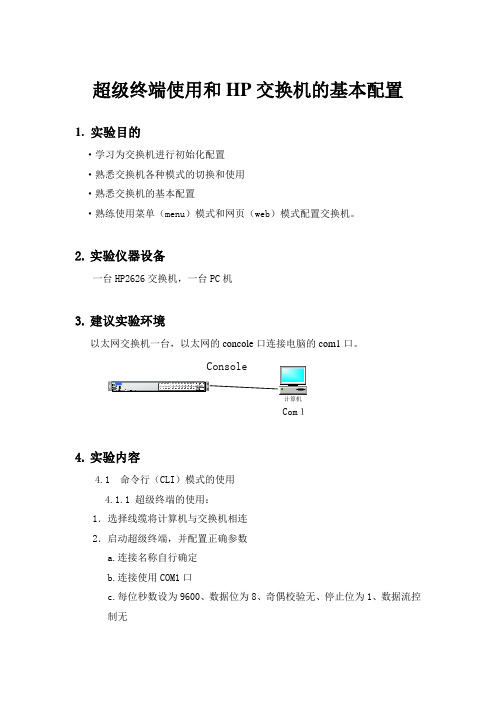
2.实验仪器设备一台HP2626交换机,一台PC机3.建议实验环境以太网交换机一台,以太网的concole口连接电脑的com1口。
ConsoleCom14.实验内容4.1 命令行(CLI)模式的使用4.1.1 超级终端的使用:1.选择线缆将计算机与交换机相连2.启动超级终端,并配置正确参数a.连接名称自行确定b.连接使用COM1口c.每位秒数设为9600、数据位为8、奇偶校验无、停止位为1、数据流控制无按ENTER键进入,显示交换机提示符4.1.2用户模式的选择用户EXEC模式——以有限的命令可用性(基本上是简单的监控和故障排除命令)提供对IOS的基本访问。
特权EXEC模式——提供对IOS的高级别的管理访问,包括在User EXEC 模式中所有可用的命令。
配置模式——允许改变这台设备的配置。
两种EXEC模式都是受口令保护的,从而允许用户限制能够访问其设备进行管理、配置和故障排除任务的人。
步骤1:登陆交换机,进入用户模式显示如下:ProCurve Switch 2626>步骤2:进入特权模式输入命令“enable”,进入特权模式。
显示如下:ProCurve Switch 2626#步骤3:进入全局配置模式输入命令“configure terminal or config”进入全局配置模式。
显示如下:ProCurve Switch 2626 (config) #步骤4:进入vlan配置模式输入命令“vlan 1”ProCurve Switch 2626 (config) # vlan 1ProCurve Switch 2626 (vlan-1) #步骤5:退出vlan配置模式输入命令“exit”ProCurve Switch 2626 (vlan-1) #exitProCurve Switch 2626 (config) #步骤6:进入端口配置模式输入命令“interface 1”ProCurve Switch 2626 (config) # interface 1ProCurve Switch 2626 (eth-1) #步骤7:退出全局配置模式使用命令“end”退出全局配置模式,进入特权模式。
新手配置交换机详细教程

新手配置交换机详细教程介绍交换机是计算机网络中的重要设备,用于连接多台计算机和网络设备,实现数据的传输和网络资源的共享。
对于初学者来说,正确地配置交换机是非常重要的,本文将提供一份新手配置交换机的详细教程,帮助你正确地配置交换机并使网络工作正常。
步骤一:物理连接首先,确保你已经正确地连接交换机到你的局域网中。
在连接之前,确认以下几点: - 交换机的电源已连接并打开。
- 交换机的端口与计算机或其他网络设备的网线正确地连接。
- 电缆质量好,无损坏和松动。
步骤二:访问交换机要配置交换机,你需要访问交换机的管理界面。
通常,交换机的管理界面可以通过以下几种方式访问: 1. 串口连接:通过串口线将计算机与交换机直接连接,并使用串口终端软件(如SecureCRT、Putty等)进行访问。
2. 网络连接:将计算机通过网线与交换机连接到同一局域网中,并使用终端软件或者Web浏览器通过IP地址访问交换机的管理界面。
步骤三:登录交换机一旦访问了交换机的管理界面,你就需要登录到交换机进行配置。
首先,需要输入正确的用户名和密码。
如果是第一次登录交换机,默认的用户名和密码通常为admin/admin或者admin/空密码。
请注意,这些用户名和密码可能会因不同的交换机厂商和型号而有所不同。
步骤四:基本设置一旦登录成功,你可以开始进行基本的交换机设置。
以下是一些常见的配置项:- 主机名:设置交换机的名称,以便于识别和管理。
- 网络协议:配置交换机的IP地址、子网掩码和网关,确保其在你的局域网中具有正确的网络配置。
- VLAN(虚拟局域网):配置不同的VLAN,以将交换机上的端口划分到不同的虚拟网络中。
步骤五:端口配置一旦完成基本设置,你可以对交换机的端口进行配置。
以下是一些重要的端口配置项: - 端口速率和双工模式:根据连接的设备和需求来设置端口的速率和双工模式。
- VLAN成员关系:将端口关联到对应的VLAN,以实现不同VLAN之间的通信。
惠普网络简介

病毒减速软件 (2005)
HP 演示万兆物理层原 型 (1998)
HP ProCurve 集线器及交换机(自 1998 年 3 月) 集线器及交换机( HP AdvanceStack
HP 在新加坡成立研发中心 (2003) PNB 开始在新加坡生产 (1992) ProCurve 认证 (2004) 众多万兆交换机 (2005)
3500yl-48G-PWR
•性能
•
所有功能和服务活动时达到线速性能
3500yl 10GbE X2 模块
2 端口 CX4 和 2 端口介质灵活的 X2
性能、功能、能力
面面俱到
20
HP ProCurve 3400cl交换机
HP ProCurve Switch 3400cl- J4905A 24G
88Gbps/64Mpps 44个自适应 个自适应10/100/1000M端口 个自适应 端口 4个双选端口(10/100/1000Base-T或者 个双选端口( 或者mini-GBIC连接) 连接) 个双选端口 或者 连接 2个可扩展万兆接口(CX4,LR) 个可扩展万兆接口( 个可扩展万兆接口 , )
为合作伙伴的成长提供极佳的机会! 为合作伙伴的成长提供极佳的机会!
3、领先的性价比的产品
(工业标准/ (工业标准/连网简单)
5400
……电信级交换机 电信级交换机
4200 5300 2810
功能
2800 2600 2600-PWR
2510 1800
2500
非网管交换机…… 非网管交换机
性/价比 价比
机箱产品
交换容量
•
5406zl 4U
•
5412zl 692Gbps/428Mpps 5406zl 346Gbps/214Mpps 5412 48个万兆端口/288个千兆端口 5406 24个万兆端口/144个千兆端口 冗余电源
惠普 HP ProCurve Switch 1700系列 交换机 说明书
抗干扰性 EN ESD 辐射 EFT/脉冲 电涌 导电 电源频率磁场 电压突降与中断 谐波 闪动 管理 备注
HP ProCurve Switch 1700-24 (J9080A)
22个自适应10/100端口(IEEE 802.3 Type 10Base-T、IEEE 802.3u Type 100Base-TX);介质类型:Auto-MDIX;双工:半双工或全双工
HP ProCurve Switch 1700系列
功能和优势
业界知名的保修服务
监控和诊断
• 端口镜像:使端口上的流量可以同时发送到网络分析器,以便进 行监控
易用性
• 带端口指示器的综合LED显示屏:可以一目了然地查看状态、活 动、速度和全双工运行情况
恢复能力和高可用性
• ProCurve/IEEE Auto-MDIX:自动适应所有10/100/1000端口上 的直连或交叉电缆
惠普网络“网”者之选
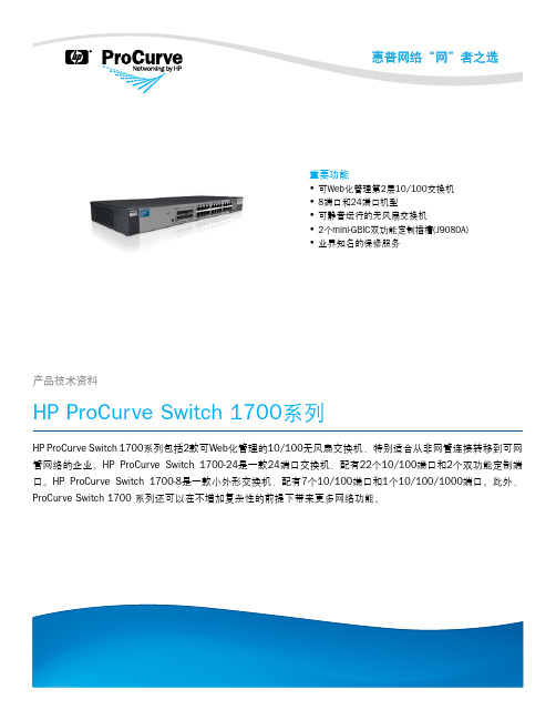
重要功能 • 可Web化管理第2层10/100交换机 • 8端口和24端口机型 • 可静音运行的无风扇交换机 • 2个mini-GBIC双功能定制插槽(J9080A) • 业界知名的保修服务
产品技术资料
HP ProCurve Switch 1700系列
HP ProCurve Switch 1700系列包括2款可Web化管理的10/100无风扇交换机,特别适合从非网管连接转移到可网 管网络的企业。HP ProCurve Switch 1700-24是一款24端口交换机,配有22个10/100端口和2个双功能定制端 口。HP ProCurve Switch 1700-8是一款小外形交换机,配有7个10/100端口和1个10/100/1000端口。此外, ProCurve Switch 1700 系列还可以在不增加复杂性的前提下带来更多网络功能。
HP ProCurve 2910al交换机系列 说明书

• 查找-解决-通知:自动查找并解决常见的网络问题,然后通知管 理员。
全新 HP ProCurve 10-GbE SFP+ 1米直连电缆(J9281A) 全新 HP ProCurve 10-GbE SFP+ 3米直连电缆(J9283A)
• 双闪存映像:可提供独立的主、辅操作系统文件,以便在升级过 程中进行备份
• 多配置文件:允许多个配置文件存储到闪存映像中。 • 易用的端口名称:允许为端口指定描述性名称
HP ProCurve 620冗余/外置电源(J8696A) HP ProCurve 100-FX SFP-LC收发器(J9054B) 全新 HP ProCurve 100-BX-D SFP-LC收发器(J9099B) 全新 HP ProCurve 100-BX-U SFP-LC收发器(J9100B) HP ProCurve Gigabit-SX-LC Mini-GBIC (J4858C) HP ProCurve Gigabit-LX-LC Mini-GBIC (J4859C) HP ProCurve Gigabit-LH-LC Mini-GBIC (J4860C) 全新 HP ProCurve 1000-BX-D SFP-LC Mini-GBIC (J9142B) 全新 HP ProCurve 1000-BX-U SFP-LC Mini-GBIC (J9143B) 全新 HP ProCurve 10-GbE SFP+ SR收发器(J9150A) 全新 HP ProCurve 10-GbE SFP+ LR收发器(J9151A) 全新 HP ProCurve 10-GbE SFP+ LRM收发器(J9152A)
电缆
安全性
• 多种用户身份验证方法:
HP交换机简明使用手册
HP交换机简明使用手册HP5400/5300及HP26002006/10目录HP交换机简明使用手册 (1)第一章交换机的初始配置 (4)1.1使用CONSOLE口进行交换机的配置 (4)1.2使用TELNET或者WEB方式对交换机进行配置 (6)1.2.1使用TELNET方式对交换机进行配置 (6)1.2.2通过WEB方式对交换机进行配置 (6)1.3 设置用户名及密码 (7)1.4 配置SNMP相关信息 (8)1.5 LLDP配置 (9)1.6密码恢复方法 (11)1.7 交换机映像更新及配置文件备份与恢复 (11)1.将配置文件备份到TFTP服务器上 (11)2.将从TFTP服务器上的配置文件恢复到交换机 (12)3.升级交换机的映象文件 (12)第二章二层相关协议设置 (13)2.1端口的命名方式 (13)2.2端口物理参数配置 (13)1.设置端口的工作模式 (14)2.对端口的流量进行限制 (14)2.3 802.1qVLAN的基本概念 (15)2.4基于端口的VLAN划分方法 (15)2.5 GVRP的配置 (16)2.6 TRUNKING(LAG)的配置 (17)2.7 生成树的基本概念(STP/RSTP)及配置方法 (17)2.7.1.生成树的基本概念 (17)2.7.2.生成树的配置方法 (19)2.8 实验 (20)一、演示设备架构 (20)二、基本操作命令 (21)三、演示配置 (22)1、5304xl (22)2、2626_1 (23)3、2626_2 (24)4、测试结果 (24)第三章第三层相关设置 (25)3.1 VLAN间路由的配置 (25)3.2 静态路由的配置 (25)3.3 RIP路由协议基本概念 (26)3.4 RIP的配置 (26)3.5 OSPF路由协议的基本概念 (29)3.6 OSPF的配置 (30)3.7路由重分发 (31)3.8 VRRP/XRRP配置 (32)3.9 DHCP Relay 的配置 (34)第四章安全与认证 (36)4.1端口安全性(MAC绑定) (36)4.2访问控制表 (37)4.2.1标准访问控制列表 (37)4.2.2扩展访问控制表 (37)4.4 802.1X认证(OPEN VLAN) (37)4.5 WEB认证 (39)4.6 MAC认证 (40)4.7病毒抑制的原理与配置 (40)第五章组播协议 (42)5.1组播基本概念 (42)5.2 IGMP的配置 (42)5.3 PIM的配置 (42)附件A:5400交换机的许可证安装与删除 (44)第一章 交换机的初始配置1.1使用CONSOLE口进行交换机的配置1.超级终端配置如下:开始-附件-通讯-超级终端,在COM口属性的窗口中选择还原默认值。
POE网络交换机用户手册说明书
Contents1.Introduction (3)2.Hardware Descriptions (4)2.1 Front Panel (4)2.2 LED Indicators (4)2.3 Rear Panel (4)2.4 Specification (5)3.Getting Started (5)3.1 Management Options (5)3.2 Using Web-based Management (6)4.Configuration (7)4.1 Welcome (7)4.2 Administrator (8)4.3 Port Management (12)4.4 VLAN Setting (15)4.5 Per Port Counter (17)Per Port Counter -> Port Counter (17)4.6 QoS Setting (18)4.7 Security (19)4.8 Spanning Tree (21)4.9 Trunking (23)4.10 DHCP Relay Agent (23)4.11 Backup/Recovery (25)4.12 Miscellaneous (26)4.13 SNMP Settings (26)4.14 Logout (27)4.15 PoE Settings (27)1. IntroductionPower-over-Ethernet (PoE) eliminates the need to run DC power to other devices on a wired LAN. Using a Power-over-Ethernet system, installers need to run only a single Category 5 Ethernet cable that carries both power and data to each device. This allows greater flexibility in the locating of network devices and, in many cases, significantly decreases installation costs.There are two system components in PoE - the PSE (Power Sourcing Equipment) and the PD (Powered Device). The IEEE 802.3af/at specification defines PSE as a device that inserts power onto an Ethernet cable. The PSE may be located at the switch (End-span configuration). or it may be a separate device located between the switch and the PD (Mid-span configuration). The PD is the natural termination of this link, receiving the power, and could be an IP phone, a WLAN access point, or any other IP device that requires power. The current is transmitted over two of the four twisted pairs of wires in a Category-5 cable.Power-over-Ethernet follows the IEEE 802.3af/at specification and is completely compatible with existing Ethernet switches and networked devices. Because the Power Sourcing Equipment (PSE) tests whether a networked device is PoE-capable, power is never transmitted unless a Powered Device is at the other end of the cable. It also continues to monitor the channel. If the Powered Device does not draw a minimum current, because it has been unplugged or physically turned off, the PSE shuts down the power to that port. Optionally, the standard permits Powered Devices to signal t0 the PSEs exactly how much power they need.The PoE switch is a multi-port fast Ethernet switch that can be used to build high-performance switched workgroup networks. This switch is a store-and-forward device that offers low latency for high-speed networking. It also features a ‘store-and-forward switching’ scheme that allows the switch to auto-learn and store source addresses in a 8K-entry MAC address table. The switch is targeted at workgroup, department or backbone computing environments.2. Hardware Descriptions2.1 Front PanelThe front panel consists of LED indications, reset button and 16/24x10/100 PoE ports + 2x10/100/1000 Uplink pots.2.2 LED IndicatorsPower LED: The Power LED lights up when the switch is connected to a power source.Link/Act LED:Green (for megabit ports): Indicates that the port is running at 100M.Green (for gigabit ports): Indicates that the port is running at 100M.Blinking: Indicates that the switch is either sending or receiving data to the port.Light off: No link.PoE LED:Green: Indicates the PoE powered device (PD) is connected and the port supplies power successfully.Light off: Indicates no powered device (PD) connected.Reset: By pressing the Reset button for 10 seconds the switch will change back to the default configuration and all changes will be lost.2.3 Rear PanelThe rear panel view of the switch consists of a AC power connector, Power Switch and Glass Fuse(AC250V 10A,Φ5*L20mm).2.4 Specification3. Getting StartedThis chapter introduces the management interface of the switch.3.1 Management OptionsThe Switch can be managed through any port on the device by using the Web-based ManagementEach switch must be assigned its own IP Address, which is used for communication with Web-Based Management. The PC’s IP address should be in the same range as the switch. Each switch can allow only one user to access the Web-Based Management at a time.Please refer to the following installation instructions for the Web-based Management.3.2 Using Web-based ManagementAfter a successful physical installation, you can configure the switch, monitor the network status, and display statistics using a web browser.Connecting to the SwitchYou will need the following equipment to begin the web configuration of your device:⏹ A PC with a RJ-45 Ethernet connection⏹ A standard Ethernet cableConnect the Ethernet cable to any of the ports on the front panel of the switch and to the Ethernet port on the PC. Login Web-based ManagementIf DHCP is not enabled on the local LAN, the switch will be able to log in to the web page with 192.168.2.1 after 2 minutes. If DHCP is enabled, the DHCP server (router) will assign the address to the switch, and use DHCP to log in to the switch. Login to the switch web page.In case no DHCP server, In order to login and configure the switch via an Ethernet connection, the PC must have an IP address in the same subnet as the switch. For example, if the switch has an IP address of 192.168.2.1, the PC should have an IP address of 192.168.2.x(where x is a number between 2 ~ 254), and a subnet mask of 255.255.255.0. Open the web browser and enter 192.168.2.1 (the factory-default IP address) in the address bar. Then press <Enter>.When the following logon dialog box appears, enter the username and password then click OK. The default username is admin and password is system.Note:If the DHCP server (routing) to the switch assigned address, you can use the Auto Discovery tool to query the switch ip4. ConfigurationThe features and functions of the switch can be configured for optimum use through the Web-based Management.4.1 WelcomeAfter a successful login you will see the screen bellows:4.2 AdministratorAdministrator -> Authentication ConfigurationHere you can enter a new Username/Password and confirm it.If the switch is used to open the DHCP environment, the switch will automatically obtain an IP address from a DHCP server, the switch for the landing web page.The factory defaultIP address: 192.168.2.1Username: adminPassword: systemAdministrator -> System IP ConfigurationThere are two ways for the switch to obtain an IP address: Static and DHCP (Dynamic Host Configuration Protocol).If the switch is used to open the DHCP environment, the switch will automatically obtain an IP address from a DHCP server, the switch for the landing web page, as shown below:When using static mode, the IP address, Subnet Mask and Gateway can be manually configured. When using DHCP mode, the Switch will first look for a DHCP server to provide it with an IP address (including network mask and default gateway) before using the default or previously entered settings. By default the IP setting is static mode with IP address is 192.168.2.1 and subnet mask is 255.255.255.0Administrator -> System StatusComment: By entering a Comment, the device can more easily be recognized on the LAN.Idle Time Security: It controls the idle time-out period for security purposes, when there is no action for a specific time span in the Web-based Management. If the current session times out (expires), the user is required a re-login before using the Web-based Management again. Selective range is from 3 to 30 minute, and the defaultsetting is 5 minutes.Administrator -> Load default settingProvide a safe reset option for the switch. All configuration settings in non-volatile RAM will be reset to factorydefault and then the switch will reboot.You must enter the password of device in order to determine the firmware needs to be updated.After a correct password the switch will erase the old firmware first.After completing the erase you will see the screen bellows. Specify the Firmware Path (or Browse for one) that you are going to use, and then click Update. The state will show ‘OK’ after completion and ‘Fail’ is firmware upgrade fails or cannot be completed for any reason.Administrator -> Reboot DeviceProvide a safe way to reboot the system. Click Reboot to restart the switch.4.3 Port ManagementPort Management -> Port ConfigurationIn this page, the status of all ports can be monitored and adjusted for optimum configuration.Enable: Enable or disable the port’s connectionAuto-Nege: Enable or disable port auto-NDI/MDIXSpeed: Copper connections can operate in Forced Mode settings (1000M Full, 100M Full, 100M Halt, 10M Full, 10M Half), Auto, or Disabled. The default setting for all ports is Auto.Duplex: Copper connections can operate in Full-Duplex or Half-Duplex ModeAddr. Learning: Enable or disable port learning MAC address.Port Management -> Port MirroringPort Mirroring is a method of monitoring network traffic that forwards a copy of each incoming and/or outgoing packet from one port of the Switch to another port where the packet can be studied. This enables network managers to better monitor network performances.TX (transmit) mode: Duplicates the data transmitted from the source port and forwards it to the Target Port. Click “all” to include all ports into port mirroring.RX (receive) mode: Duplicates the data that received from the source port and forwards it to the Target Port. Click “all” to include all ports into port mirrori ng.Both (transmit and receive) mode: Duplicate both the data transmitted from and data sent to the source port, and forwards all the data to the assigned Target Port. Click “all” to include all ports into port mirroring.The target ports will stop mirroring packets if there are unknown tags or destination packets sent out by source ports.Port Management -> Bandwidth ControlThe Bandwidth Control page allows network managers to define the bandwidth settings for a specified port’stransmitting and receiving data rates.TX Rate: This allows you to enter data receive rate from 0 to 255 (base on speed base), 0 for full speed. RX Rate: This allows you to enter data transmit rate from 0 to 255 (base on speed base), 0 for full speed. Speed Base:Port Management -> Broadcast Storm ControlThe Broadcast Storm Control feature provides the ability to control the receive rate of broadcast packets. Once a packet storm has been detected, the Switch will drop packets coming into the Switch until the stormhas subsided.4.4 VLAN SettingVLAN Setting -> VLAN ModeA VLAN is a group of ports that can be anywhere in the network, but communicate as though they were in the same area. VLANs can be easily organized to reflect department groups (such as R&D, Marketing), usage groups (such as e-mail), or multicast groups (multimedia applications such as video conferencing), and therefore help to simplify network management by allowing users to move devices to a new VLAN without having to change any physical connections.Prot Based VLAN: Port-Based VLANs are the simplest and most common form of VLAN. It assigns the appliance LAN ports to VLANs, effectively transforming the appliances. You can assign multiple ports to the same VLAN, or each port to a separate VLAN.802.1Q VLAN: By default, 802.1Q VLAN is disabled. With 802.1Q VLAN enabled, the VLAN VID 1 is created by default with an empty VLAN name field and all ports are configured as “Untagged” members.VLAN SettingAdd VLAN: Click to create a new VLAN name and to select VLAN ports. The VLAN name should be less than 10 characters. To save the members in a group, click Add.VLAN Setting ->VLAN Setting ->4.5 Per Port CounterPer Port Counter -> Port CounterThe Statistics screen displays the status of each port packet count.4.6 QoS SettingQoS Setting -> Priority ModeQoS Setting -> Port, 802.1p ,IP/DS basedQoS Setting -> TCP/UDP Port BasedSecurity -> MAC Address BindingSecurity -> Scan MACSecurity -> TCP/UDP FilterSecurity -> Web Management FilterSpanning Tree -> STP Bridge SettingsSpanning Tree -> STP Port SettingsSpanning Tree -> Loopback Detection4.9 TrunkingTrunking -> Link Aggregation SettingsThe Trunking function allows the switch to combine two or four ports together to increase bandwidth. Select the Trunking Groups, choose the Members to be grouped together, and then click Submit to activate the selected Trunking Groups.4.10 DHCP Relay AgentDHCP Relay Agent -> DHCP Relay AgentDHCP Relay Agent -> Relay ServerDHCP Relay Agent -> VLAN MAP Relay Agent4.11 Backup/RecoveryAllow the current configuration settings to be saved to a file (not including the password), and if necessary,you can restore configuration settings from the file.Backup or restore the configuration file to or from your local drive.Click Download to save the current settings to your disk.Click Browse to browse your inventories for a saved backup settings file.Click Update after selecting the backup settings file you want to restore.Switch will reboot after restore and all current configurations will be lost4.12 Miscellaneous Miscellaneous -> Miscellaneous Settings4.13 SNMP Settings4.14 LogoutClick this to end this sessionIf you close the web browser without clicking the Logout button, it will be seen as an abnormal exit and the login session will still be occupied.4.15 PoEPoE -> PoE SettingThis section provides PoE (Power over Ethernet) Configuration and PoE output status of PoE Switch.Main Power consumption: The Statistics screen displays the total Watts usage of PoE Switch.Status: Can enable or disable the PoE function.Class: Class 0 is the default for PDs. However, to improve power management at the PSE, the PD may opt to provide a signature for Class 1 to 4.The PD is classified based on power. The classification of the PD is the maximum power that the PD willdraw across all input voltages and operational modes. A PD shall return Class 0 to 4 in accordance with theCurrent (mA): It shows the PoE device current Amp.PoE -> PoE Power DelayThis section provides PoE Power Delay Configuration.Delay Mode: Enable or disable the port’s PoE Power Delay function.Delay Time: Set PoE power delay time (0~300).PoE -> PoE SchedulingPoE Schedule user can configure a duration time for PoE port as default value does not provide power.: Please enable NTP and correct the System Time first.As default value, all PoE Schedule Profile functions are disabledPlease use mouse to click on the block about what time you want to supply power for PoE port. PoE -> NTP SettingThis section provide the NTP Configuration of PoE SwitchSystem Time: Display current time informationNTP Server: Allow assign #1 or #2 NTP server IP address manuallyTime Zone: Allow select the time zone according to current locationPoE -> PoE Auto-checkThe PoE Switch can be configured to monitor connected PD’s status in real-time via ping action. Once the PD stops working and without response, the PoE Switch is going to restart PoE port power, and bring the PD back to work. It will greatly enhance the reliability and reduces administrator management burden.Need to write the correct address, you can open auto-check function.Set Port No.: Select the port witch you want to set IP AddressIP Address: Allow assign IP address witch you want to monitorChecking Time: Select time interval of ping action (1-10Min)Reset Delay Time: Select time PD Reset time (1-3Seconds)Enable Checking Port. No: Select the port witch you want to enable PoE Auto-check --------------------------- End-------------------------。
无线通信-HP ProCurve配置说明-如何利用集中管理功能设置强大的可扩展无线连接

简介 ...................................................................2前提条件 ............................................................3网络图 ................................................................4配置无线接入点 (5)配置服务控制器 (9)安装来宾管理工具 (15)参考文档 (18)HP ProCurve 配置说明 — 中小型企业无线解决方案如何利用集中管理功能设置强大的可扩展无线连接1. 简介:独立接入点可以提供基于控制器的集中管理功能本文将通过几个简单的步骤,展示适用于小型和成长型企业的安全无线网络设置方法。
以下解决方案带有简单的来宾访问部署选项,特别适用于需要在无线网络中实施漫游和集中管理功能的企业。
借助此款采用智能接入点的分布式可扩展无线HP ProCurve架构,您能够从独立接入点(HP ProCurve Access PointMSM 310或HP ProCurve Access Point MSM410)轻松转换到以HP ProCurve Access Controller MSM710为中心的、集成的、集中管理的移动解决方案。
这些智能接入点均采用集中配置,可以直接转发无线流量,而不是将其重新路由到控制器,因而消除了单点故障,提高了网络性能。
同时,您还可以通过这些接入点轻松迁移到802.11n技术,实现不同无线基站技术的混合使用。
另外,企业内的每一个员工均可通过这些无线来宾访问管理软件为来宾、客户以及合作代理商分配相应的网络访问权限。
应用环境:您的企业正在蓬勃发展。
您希望通过一款可扩展的无线解决方案充分发挥已有产品的强大功能,并根据业务需求轻松迁移到高性能IEEE 802.11n无线连接。
网络交换机的详细配置方法

交换机配置方法网络交换机的详细配置方法(图文教程)06-26 21:56:48作者:脚本之家在“傻瓜”型交换机肆意的今天,如何配置交换机对很多人来说都是一门高深的学问,甚至在被问及交换机如何配置时,有人会反问道:交换机还需要配置的么?确实,交换机的配置过程复杂,而且根据品牌及产品的不同也各不相同,那么我们应该如何配置交换机呢?本文将以图文结合的方式来具体介绍一下交换机配置,希望对大家有所帮助。
交换机本地配置谈起交换机本地配置,首先我们来看一下交换机的物理连接。
交换机的本地配置方式是通过计算机与交换机的“Console”端口直接连接的方式进行通信的。
计算机与交换机的“Console”端口连接网管型交换机一般都有“Console”端口,用于进行交换机配置。
物理连接完成后就要进行交换机软件配置,下面以思科“Catalyst 1900”为例来说明如何进行交换机软件配置:第1步:单击“开始”按钮,在“程序”菜单的“附件”选项中单击“超级终端”,弹出如图所示界面。
第2步:双击“Hypertrm”图标,弹出如图所示对话框。
这个对话框是用来对立一个新的超级终端连接项。
第3步:在“名称”文本框中键入需新建超的级终端连接项名称,这主要是为了便于识别,没有什么特殊要求,我们这里键入“Cisco”,如果您想为这个连接项选择一个自己喜欢的图标的话,您也可以在下图的图标栏中选择一个,然后单击“确定”按钮,弹出如图所示的对话框。
第4步:在“连接时使用”下拉列表框中选择与交换机相连的计算机的串口。
单击“确定”按钮,弹出如图所示的对话框。
第5步:在“波特率”下拉列表框中选择“9600”,因为这是串口的最高通信速率,其他各选项统统采用默认值。
单击“确定”按钮,如果通信正常的话就会出现类似于如下所示的主配置界面,并会在这个窗口中就会显示交换机的初始配置情况。
Catalyst 1900 Management ConsoleCopyright (c) Cisco Systems,Inc。
HP_ProCurve_2910al_Switch_Series(产品说明)
• 交换机管理登录安全性:可以要求进行RADIUS或TACACS+身份验
-基于MAC的身份验证:根据客户端的MAC地址,利用RADIUS服 证,以确保安全的交换机CLI登录
务器对客户端进行身份验证
• STP BPDU端口保护:拦截端口上不必要的桥接协议数据单元
• 身份验证的灵活性:
(BPDU),以免假冒BPDU攻击
• STP Root Guard:保护根网桥受到恶意攻击或发生配置错误
-每端口可同时进行IEEE 802.1X以及Web或MAC身份验证:交换 机端口将接受任何IEEE 802.1X、Web或MAC身份验证
• 访问控制列表(ACL):提供基于源/目标IP地址/子网及源/目标TCP/
• 自定义信息显示:在用户登陆到交换机时显示安全策略 • 按端口广播限制:选择配置大流量端口上行链路的广播控制
管理工作
到8个队列
• Secure Shell (SSHv2):加密传输的所有数据,确保IP网络上安全 • 第4层优先级:可根据TCP/UDP端口号进行优先化
的命令行界面(CLI)远程访问
• 服务级别(CoS):根据IP地址、IP服务类型(ToS)、L3协议、TCP/
• Secure FTP/SCP:确保与交换机进行安全的文件传输,以免下载 UDP端口号、源端口和DiffServ,设置IEEE 802.1p优先级标记
-每端口多个IEEE 802.1X用户:可为每端口上的8个IEEE 802.1X 用户提供身份验证,避免其他用户在进行IEEE802.1X身份验证 时产生“重叠”
• USB Secure Autorun (需要ProCurve Manager Plus):使用USB闪存 盘部署、诊断并升级交换机,可配合安全证书一起使用以防篡改
- 1、下载文档前请自行甄别文档内容的完整性,平台不提供额外的编辑、内容补充、找答案等附加服务。
- 2、"仅部分预览"的文档,不可在线预览部分如存在完整性等问题,可反馈申请退款(可完整预览的文档不适用该条件!)。
- 3、如文档侵犯您的权益,请联系客服反馈,我们会尽快为您处理(人工客服工作时间:9:00-18:30)。
惠普Procurve以太网交换机配置指南-Version-1.0中国惠普有限公司Administrator2011年5月5日惠普ProCurve以太网交换机安装配置指南Version1.0产品介绍ProCurve 6120系列交换机分为两种型号:●6120G/XG●6120XG产品名称的规则:以6120产品的G/XG为例,G和XG都指端口速率,其中G表示1Gb per second,XG表示10Gb per second;”/”以前的部分特指内部端口速率,”/”以后的部分特指外部端口速率。
前面板及端口介绍:端口•10GbE CX4—The CX4 interface requires the use of copper cabling, similar to the variety used in InfiniBand technology, and is designed to work up to a distance of15 m. CX4 technology is an attractive solution because ithas the lowest cost per port of all 10Gb interconnects, at the expense of range. CX4 has a bigger form factor than either SFP or SFP+.•10GbE XFP ports—These 10GbE ports support SR (multi-mode fiber, 300 m) and LR (single-mode fiber, 10 km) optic transceivers based on the XFP version of the small form factor pluggable specification. XFP transceivers have a smaller form factor compared to several standards (XENPAK, X2, XPAK) that preceded it. The XFP ports support Industry Standard Servers (ISS) optics only.•1GbE SFP ports—These 1GbE ports support SX (multi-modefiber, 550 m) and LX (single-mode fiber, 10 km) optictransceivers based on the SFP version of the small formfactor pluggable specification using an LC physicalconnector. These ports also support 1000BASE-T copperconnections using an RJ-45 connector. The SFP ports supportISS and ProCurve optics.•10/100/1000 RJ-45 ports—These ports support standard RJ-45 Ethernet cables and each port can operate at one ofthree autosensing speeds.•5x 10GbE SFP+ ports—These five ports are dedicated10GbE SFP+ ports that support SR (multi-mode fiber, 300 m), LR(single-mode fiber, 10 km), and LRM (multi-mode fiber, 220m) optic SFP+ transceivers.•2x 10GbE SFP+ ports—Individually, the two ports labeled23 and 24 can be used as either external 10GbE SFP+ portsor internal 10GbE switch-to-switch (cross-link) ports. ForSFP+ connectivity, these ports support the same fiber optictransceivers as the other SFP+ ports.•Internal Network Ports—The 6120G/XG also has “internal”Ethernet ports that function as downlinks to devices in the enclosure. The internals ports are essentially communication interfaces used to transfer data to and from server blades,storage blades, and even another 6120G/XG (if it is installed in an adjacent bay of the enclosure). The internal ports use the enclosure’s midplane circuitry to communicate with the other c-Class enclosure components.•Management Port—The IP address within the OA subnet that you assign to the blade switch is used by a switch component known as Out-Of-Band Management (OOBM).交换机系统指示灯:Module status LED:绿色表示交换机工作正常;橙色表示有故障Module locator LED:用户可以通过命令chassislocate <off|on|blink>来控制其状态,方便用户找到此交换机端口指示灯介绍:Link status LED:绿色表示已连接;橙色表示有故障Link activity LED绿色闪烁表示正在通讯RJ-45指示灯绿色闪烁表示端口正在10/100Mb per second速率通讯橙色闪烁表示端口正在1000Mb per second速率通讯管理口介绍:Mini USB接口,交换机产品包装里都有对应的线缆;使用其管理交换机时,需要先安装相应的驱动程序,并通过终端模拟器软件访问。
驱动程序如下USB Console Driver for HP ProCurve 6120 Series Ethernet Blade Switches for WindowsC LEAR AND R ESET C ONTROL B UTTONS:Clear用来清除用户密码;Reset使交换机重启;当Clear和Reset同时按,将使交换机恢复出厂配置配置细则:管理接口ProCurve 6120系列交换机管理接口有三个:Mini USB模拟串口,与OA直连的内部串口,与OA直连的Out-Of-Band Management (OOBM)以太网接口M INI USB访问Mini USB分别连接交换机和PC的USB接口,安装驱动后,在终端模拟器软件中选择连接端口’COM4’,串口属性9600/n/8/1OA内部串口访问telnet <OA IP addr>connect interconnect <bay number>通过以上两种串口访问方式可以配置OOBM以太网接口的IP地址OOBM以太网接口可以用telnet 访问,或者用IE 访问。
建议在做配置时使用telnet 方式。
这样的好处是:1.命令行方式便于把事先制订好的配置脚本粘贴到终端上执行2.避免了IE 方式可能遇到的Java 版本问题,Java 响应速度慢的问题常用交换机参数配置OOBM端口管理方法:端口启用/禁用(默认情况下是启用状态)ProCurve# configureProCurve(config)# oobmProCurve(oobm)# enable ##启用ProCurve(oobm)# disable ##禁用DHCP获取IPProCurve# configureProCurve(config)# oobmProCurve(oobm)# ip address dhcp-bootp手工指定IPProCurve# configureProCurve(config)# oobmProCurve(oobm)# ip address <IP-ADDR/MASK-LENGTH> ## IP-ADDR指32位IP地址的十进制表示;配置网关ProCurve# configureProCurve(config)# oobmProCurve(oobm)# ip default-gateway<IP-ADDR>用户管理交换机默认有manager和operator两个用户,默认密码为空。
修改密码ProCurve# configureProCurve(config)# password managerNew password for manager:Please retype new password for manager:ProCurve(config)#password operatorNew password for operator:Please retype new password for operator:修改系统名称ProCurve# configureProCurve(config)# hostname TTETTE(config)#前面板恢复出厂按钮的启用/禁用ProCurve(config)# front-panel-securityfactory-reset Enable/Disable factory-reset ability password-clear Enable/Disable password clearpassword-recovery Enable/Disable password recovery.清空配置文件ProCurve# erase startup-config保持配置到交换机ProCurve# write memory保持配置到TFTP服务器ProCurve# copy running-config tftp <IP-ADDR><FILENAME-STR>常用交换机状态查看查看固件版本ProCurve# show flashProCurve# show version查看当前配置文件ProCurve# show running-config查看端口状态ProCurve# show interfaces <port-name>查看OOBM状态ProCurve# show oobm查看VLAN状态ProCurve# show vlans查看交换机系统ProCurve# show system查看交换机日志ProCurve# show tech allProCurve# show logging常用交换机应用配置配置VLAN及VLAN TAGGINGProCurve# configureProCurve(config)# vlan 10 ##建立Vlan 10ProCurve (vlan-10)# name train_the_engineer ##为Vlan 10命名ProCurve# show vlans 10 ##显示所有vlan信息,可以发现Vlan 10名称已经成功更改TaggedProCurve (vlan-10)# tagged ethernet D1-D4 ##将端口D1到D4加入到新的vlanProCurve# show vlans 10 ##显示vlan 10状态,可以发现D1到D4端口已经成功加入vlan 10ProCurve# show running-config ##显示当前配置,可以发现D1到D4端口不但属于vlan 10,同时属于DEFAULT_VLAN(Vlan 1)UntaggedProCurve (vlan-10)# untagged ethernet D1-D4 ##将端口D1到D4加入到新的vlanProCurve# show vlans 10 ##显示vlan 10状态,可以发现D1到D4端口已经成功加入vlan 10ProCurve# show running-config ##显示当前配置,可以发现D1到D4端口只属于vlan 10VLAN及Trunk配置实例注意以下配置要按顺序执行1.ProCurve# configure2.ProCurve(config)# interfaces ethernet 1-4 ##进入端口1-4配置模式3.ProCurve (eth-1-4)# lacp active ##选择LACP协议模式为”active”4.ProCurve(eth-1-4)# end5.ProCurve# configure6.ProCurve(config)#trunk ethernet 1-4 trk8 lacp ##将端口1到4加入到Trunk Group 8中,同时启用LACP协议协商;同一Trunk Group中所有端口的LACP mode必须一致7.ProCurve(config)# vlan 28.ProCurve (vlan-2)# tagged ethernet 1-4 ##将端口1到4加入到vlan 2,这里不能用”untagged”9.ProCurve (vlan-2)# vlan 310.ProCurve (vlan-3)# tagged ethernet 1-4 ##将端口1到4加入到vlan 311.ProCurve(eth-1-4)# end配置UFDProCurve(config)# uplink-failure-detectionProCurve(config)# uplink-failure-detection-track 1links-to-monitor 20 links-to-disable 3,12ProCurve(config)# uplink-failure-detection-track 5links-to-monitor 17-18 links-to-disable 7,14Switch# sh ufdUplink Failure Detection InformationUFD Enabled : YesTrack ID | Monitored Links Links to Disable LtM State LtD State------------ + ------------------ ------------------ ------------- ------------1 | 20 3,12 Down Auto-Disabled5 | 17-18 7,14 Up Up固件版本升级通过管理端口升级升级前的准备建立TFTP服务器,保证TFTP服务器能够与OOBM通讯,并将固件文件存入TFTP服务器root目录执行升级步骤ProCurve# copy tftp flash <TFTP IP addr><固件文件名><primary|secondary> oobm ##由于是经由OA及OOBM端口升级,故关键字”oobm”必须加上,否则无法升级ProCurve# show flash ##查看固件版本。