制动系统设计手册(NEW)
(完整word版)制动系统设计
GD12A电动汽车行车制动系统设计毕业设计说明书姓名:俞翼鸿专业:汽车维修与检测班级:(2)指导老师: 邹章鸣南昌理工学院机械工程系1.。
目录摘要Troduction前言第一章绪论 (6)1。
1 制动系统设计的意义 (6)1。
2 制动系统研究现状 (6)1.3 本次制动系统应达到的目标 (6)1.4 本次制动系统设计要求 (6)第二章制动系统方案论证分析与选择 (7)2.1 制动器形式方案分析 (7)2。
1.1 鼓式制动器 (7)2。
1。
2 盘式制动器 (9)2。
2 制动驱动机构的结构形式选择 (10)2.2.1 简单制动系 (10)2。
2。
2 动力制动系 (10)2。
2。
3 伺服制动系 (11)2。
3 液压分路系统的形式的选择 (11)2.3.1 II型回路 (11)2.3.2 X型回/路 (12)2。
3。
3 其他类型回路 (12)2。
4 液压制动主缸的设计方案 (12)第三章制动系统设计计算 (15)3.1 制动系统主要参数数值 (15)3.1.1 相关主要技术参数 (15)3.1.2 同步附着系数的分析 (15)3.2 制动器有关计算 (16)3.2。
1 确定前后轴制动力矩分配系数β (16)3。
2。
2制动器制动力矩的确定 (16)3.2。
3 后轮制动器的结构参数与摩擦系数的选取 (17)3.2.4 前轮盘式制动器主要参数确定 (18)3。
3 制动器制动因数计算 (19)3.3.1 前轮盘式制动效能因数 (19)3.3。
2 后轮鼓式制动器效能因数 (19)3。
4 制动器主要零部件的结构设计 (20)第四章液压制动驱动机构的设计计算 (22)4。
1 后轮制动轮缸直径与工作容积的设计计算 (22)4.2 前轮盘式制动器液压驱动机构计算 (23)4.3 制动主缸与工作容积设计计算 (24)4.4 制动踏板力与踏板行程 (24)4.4。
1 制动踏板力 (24)4.4.2 制动踏板工作行程 (25)第五章制动性能分析 (26)5.1 制动性能评价指标 (26)5.2 制动距离S (26)5。
汽车制动系统设计说明书
目录1、汽车制动系统概述及设计要求 (4)1.1 概述 (4)1.1.1制动系统的组成 (4)1.1.2 制动系统的类型 (4)1.2 设计制动系统时应满足的要求 (5)2、整车性能参数: (6)3、制动器形式的选择 (6)4、鼓式与盘式制动器主要参数的确定 (8)4.1制动鼓内径D (8)4.2摩擦衬片宽度b和包角β (8)4.3摩擦衬片起始角 0 (9)4.4制动器中心到张开力0F作用线的距离e (10)4.5制动蹄支撑点位置坐标a和c (10)4.6摩擦片摩擦系数 (10)4.7制动盘直径D (10)4.8制动盘的厚度h (11)4.9摩擦衬块内外半径的确定 (11)4.10制动衬块工作面积A (11)5、鼓式制动器主要零部件的设计 (12)5.1制动蹄 (12)5.2制动鼓 (12)5.3摩擦衬片 (13)5.4摩擦材料 (14)5.5蹄与鼓之间的间隙自动调整装置 (14)5.6制动支承装置 (16)5.7制动轮缸 (16)5.8张开机构 (16)6、盘式制动器主要零部件设计计算 (17)6.1 滑动钳体 (17)6.2 固定支架 (17)6.3 制动盘 (17)6.4 制动块 (17)6.5同步附着系数的确定 (19)6.6地面对前、后轮的法向反作用力 (19)6.7制动力分配系数的确定β[]4 (20)6.8前、后制动器制动力矩的确定[]4 (20)6.9应急制动和驻车制动所需的制动力矩[]1 (21)6.9.1应急制动 (21)6.9.2驻车制动 (22)6.9.3衬片磨损特性的计算 (23)7、制动驱动机构的设计与计算 (25)7.1 制动驱动机构的形式 (25)7.2 分路系统 (26)7.3 液压制动驱动机构的设计计算 (28)7.3.1 制动轮缸直径的确定 (28)7.3.2 制动主缸直径的确定 (29)7.3.3制动踏板力p F和制动踏板工作行程p S (30)7.3.4真空助力器的设计计算 (31)8、制动性能分析 (31)8.1制动性能评价指标 (31)8.2 制动效能 (31)8.3 制动效能的恒定性 (32)8.4 制动时汽车的方向稳定性 (32)8.5制动器制动力分配曲线分析 (32)8.6制动减速度j和制动距离S (34)参考文献 (35)1、汽车制动系统概述及设计要求1.1 概述使行驶中的汽车减速甚至停车,使下坡行驶的汽车的速度保持稳定,以及使已经停驶的汽车保持不动,这些作用统称为汽车制动。
毕业设计阁瑞斯轻型客车制动系统设计说明书

摘要随着高速公路的不断发展,汽车车速的不断提高,车流密度也不断增大。
现代汽车对制动系的工作可靠性要求日益提高。
因为只有制动性能良好,制动系工作可靠的汽车才能充分发挥出其高速行驶的动力性能并保证行驶的安全性。
由此可见,本次制动系统设计具有实际意义。
对于福田风景轻型客车的制动系统设计,首先制定出制动系统的结构方案,本设计确定采用前盘后鼓式制动器,串联双腔制动主缸,HH型交叉管路布置。
其次计算制动系统的主要设计参数(确定同步附着系数,制动力分配系数,制动器最大制动力矩),制动器主要参数设计和液压驱动系统的参数计算。
再次利用计算机辅助设计绘制装配图,布置图和零件图。
最终进行制动力分配编程,对设计出的制动系统的各项指标进行评价分析。
通过本次设计的计算结果表明设计出的制动系统是合理的、符合标准的。
其满足结构简单、成本低、工作可靠等要求。
关键词:福田风景轻型客车;制动系统设计;前盘后鼓式制动器;制动主缸AbstractWith the continuous development of highways, the continuous improvement of vehicle speed, traffic density has increased continuously. Hyundai Motor brake on the work of the increasing reliability requirements. Only good braking performance, the braking system of reliable car to give full play to its high-speed driving performance and to ensure that the momentum on security. Evidently, this braking system design of practical significance.For the design of Foton View Light Bus,First developed structure of the braking system, the design determined by pre-and post-drum brakes, dual-chamber tandem brake master cylinders, HH-cross-line layout. This was followed by calculation of the main braking system design parameters (attachment coefficient determined simultaneously, the braking force distribution coefficient, the biggest brake brake torque), the main parameters of design and brake hydraulic drive system parameters. Drawing once again use computer-aided design assembly drawing, layout plans and parts. Final braking force distribution of programming, the design of the braking system of indicators to evaluate the analysis.Through this design calculations designed to show that the braking system is reasonable, in line with standards. To meet its structure is simple, low cost, reliability requirements.Keywords:Foton View Light Bus;Brake System Design;Qianpanhougu brake;Brake master cylinders目录第1章绪论 (1)1.1制动系统工作原理 (1)1.2汽车制动系统的组成 (2)1.3汽车制动系统的类型 (2)1.4 汽车制动系统的功用和要求 (3)1.4.1 汽车制动系统的功用 (3)1.4.2 汽车制动系统的设计要求 (3)第2章制动系统设计方案 (4)2.1 制动器结构形式方案 (4)2.2液压制动管路布置方案 (6)2.3制动主缸的设计方案 (7)2.4制动驱动机构形式方案 (8)2.4.1简单制动系 (9)2.4.2动力制动系 (9)2.4.3伺服制动系 (9)第3章制动系统主要参数确定 (10)3.1 轻型货车主要设计参数 (10)3.2 同步附着系数的确定 (10)3.3 制动器制动力分配系数β的确定 (11)3.4 前后制动器最大制动力矩的确定 (12)3.5 制动器主要参数的确定 (12)3.5.1 制动鼓直径D的确定 (12)3.5.2 制动器主要参数的确定b和包角θ的确定 (13)θ的确定 (13)3.5.3 摩擦衬片起始角3.5.4 制动器中心到张开力作用线距离e的确定 (13)3.5.5 制动蹄支销连线至制动器中心值a的确定 (13)3.5.6 支销中心距c2的确定 (13)3.5.7 摩擦片摩擦系数μ的确定 (13)第4章制动器的设计与计算 (14)4.1 前、后鼓式制动器制动转矩计算 (14)4.1.1 制动蹄的压力中心 (14)4.1.2 制动蹄的效能因数 (14)4.1.3 每一制动器的制动转矩 (15)4.2 制动性能计算 (15)4.2.1 制动减速度j (15)4.2.2 制动距离 (15)第5章制动驱动机构设计 (17)5.1 制动轮缸直径d的确定 (17)d的确定 (17)5.2 制动主缸直径F的确定 (17)5.3 制动踏板力P5.4 制动踏板工作行程的确定 (18)第6章评价分析 (19)6.1 汽车制动性能评价指标 (19)6.2 制动效能 (19)6.3 制动效能的恒定性 (19)6.4 制动时汽车的方向稳定性 (19)6.5 前、后制动器制动力分配 (20)6.5.1 地面对前、后车轮的法向作用力 (20)6.5.2 理想的前、后制动器制动力分配曲线 (21)6.6 制动系统的发展趋势 (22)第7章结论 (26)参考文献 (27)致谢 (28)附录一外文翻译 (29)附录二相关程序 (38)第1章绪论汽车制动系是用于使行驶中的汽车减速或停车,使下坡行驶的汽车的车速保持稳定以及使已停驶的汽车在原地(包括在斜坡上)驻留不动的机构。
汽车制动系统手册说明书
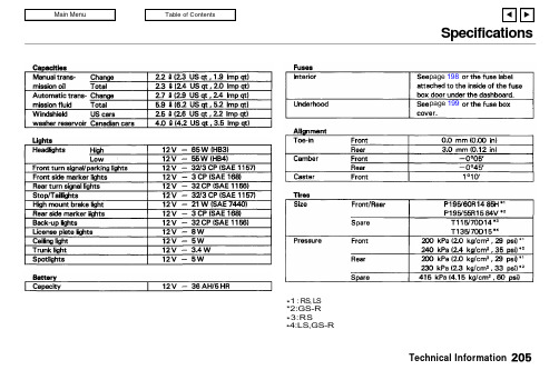
SpecificationsTechnical Information*1 : RS, L S *2:GS-R *3:RS*4:LS,GS-Rpage 198page199Anti-lock Brake SystemThe Anti-lock Brake System (ABS)is standard equipment on the LS and GS-R models. It is not available on the RS model.The ABS works by measuring how fast the wheels are turning during braking and comparing their speed.If any wheel is rotating much slower than the others (on the verge of locking up and skidding),the system reduces hydraulic pressure to that wheel's brake caliper. When that wheel's speed matches the other wheels, the system applies normal hydraulic pressure. This can take place several times per second at each wheel. You feel the ABS working as rapid pulsations in the brake pedal.Each wheel has a wheel speed sensor assembly. As the wheel rotates, the sensor sends electrical pulses to the ABS control unit. The pulse frequency varies with the wheel speed.The electrical output of the ABS control unit is connected to the modulator/solenoid unit. During braking, the ABS control unit monitors the pulse frequencies from the four wheels. When the control unit detects a wheel locking up, it energizes the appropriate solenoid in the modulator/solenoid unit. There are three solenoids: one for each front wheel, and one for the rear wheels. The energized solenoid reduces hydraulic pres-sure to one side of a modulatorvalve. This, in turn, reduces hydrau-lic pressure in the brake line going to the affected wheel. When that wheel speeds up because of the re-duced braking effort, the controlunit de-energizes the solenoid. This builds hydraulic pressure on the modulator valve. The pressure in-creases in the hydraulic line to the wheel.For the system to react quickly, the modulator/solenoid unit must have brake fluid under high pressure.This is supplied by an accumulator that is pressurized by an electric pump. A pressure-sensing switch on the accumulator controls this pump.The control unit also contains error detection circuitry. It monitors the operation of the wheel sensors,solenoids, pump, and electronics. If the control unit detects any faults,it shuts off power to the pump motor and solenoids. The light on the instrument panel comes on.The brakes then work like aconventional system without anti-lock capabilities.Technical InformationSupplemental Restraint SystemThe SRS includes the steering wheel airbag assembly, sensors in the dashboard, and a control unit with sensors behind the center console.(All models except the Canadian RS model)The system also has a dashboard-mounted airbag assembly for the passenger.The sensors are decelerometers,set to trigger in a severe frontal impact that generates more force than a 25 mile per hour crash into a parked vehicle of similar size. For the SRS to activate, at least two sensors must trigger. This duplica-tion is to prevent accidental activa-tion.When the control unit receives trigger signals from at least two sensors, it sends voltage to the airbag. The control unit stores this charge in capacitors to insure reliability even if a severe impact damages the car's battery or electrical connections.The electrical charge sent to the airbag assembly ignites its propel-lant, which burns instantaneously.The gas produced by the burning propellant inflates the airbag instantly.The airbag is vented so it stays inflated for only an instant and does not block the driver's vision.Smoke from the burned propellant comes out of the airbag and into the car's interior. This is normal and does not mean there is a fire.The airbag collapses onto the driver's lap.The airbag must be replaced after it is activated. After use, your Acura dealer must check the complete Supplemental Restraint System and replace the airbag assembly.To ensure long-term reliability, the SRS uses gold-plated electrical connections throughout. Exposed components are sealed with epoxy.The control unit monitors the SRS circuitry whenever the ignition is ON (II). If the control unit senses any faults, it turns on the SRS indicator light on the instrument panel. Take the car to your Acura dealer to diagnose and repair the system as soon as possible.The SRS needs no regular mainte-nance other than an inspection by your Acura dealer ten years after manufacture.Technical InformationEmission ControlsThe burning of gasoline in your car's engine produces several by-products. Some of these are carbon monoxide (CO), oxides of nitrogen (NOx) and hydrocarbons (HC).Gasoline evaporating from the tank also produces hydrocarbons. Con-trolling the production of NOx, CO,and HC is important to the environ-ment. Under certain conditions of sunlight and climate, NOx and HC react to form photochemical "smog."Carbon monoxide does not contri-bute to smog creation, but it is a poisonous gas.The Clean Air ActThe United States Clean Air Act*sets standards for automobile emissions. It also requires that automobile manufacturers explain to owners how their emission controls work and what to do to maintain them. This sectionsummarizes how the emission con-trols work. Scheduled maintenance is on page 125.* In Canada, Acura vehicles comply with the Canadian Motor Vehicle Safety Standards (CMVSS) for Emissions valid at the time they are manufactured.Crankcase Emission Control SystemYour car has a Positive Crankcase Ventilation System. This keeps gasses that build up in the engine's crankcase from going into the atmosphere. The Positive Crank-case Ventilation valve routes them from the crankcase back to the intake manifold. They are then drawn into the engine and burned.Evaporative Emission Control SystemAs gasoline evaporates in the fuel tank, an evaporative emissioncontrol canister filled with charcoal adsorbs the vapor. It is stored in this canister while the engine is off.After the engine is started andwarmed up, the vapor is drawn into the engine and burned during driving.Technical InformationEmission ControlsExhaust Emission Controls The exhaust emission controls include three systems: PGM-FI,Ignition Timing Control and Three Way Catalytic Converter. These three systems work together to control the engine's combustion and minimize the amount of HC,CO, and NOx that comes out the tailpipe. The exhaust emission control systems are separate from the crankcase and evaporative emission control systems.PGM-FI SystemThe PGM-FI System uses sequen-tial multiport fuel injection.It has three subsystems: Air Intake,Engine Control, and Fuel Control.The Engine Control Module (ECM)uses various sensors to determine how much air is going into the engine. It then controls how much fuel to inject under all operating conditions.Ignition Timing Control System This system constantly adjusts the ignition timing, reducing the amount of HC, CO and NOx produced.Three Way Catalytic Converter The three way catalytic converter is in the exhaust system. Through chemical reactions, it converts HC,CO, and NOx in the engine's exhaust to carbon dioxide (CO 2),dinitrogen (N 2), and water vapor.Replacement PartsThe emission control systems are designed and certified to work to-gether in reducing emissions to levels that comply with the Clean Air Act. To make sure the emis-sions remain low, you should use only new genuine Acura replace-ment parts or their equivalent for repairs. Using lower quality parts may increase the emissions from your car.The emissions control systems are covered by warranties separate from the rest of your car. Read your warranty manual for more information.Technical InformationThree Way Catalytic ConverterThe three way catalytic converter contains platinum, palladium and rhodium. These metals serve as catalysts, promoting chemical reactions to convert the exhaust gasses without affecting the metals.The catalytic converter is referred to as a three-way catalyst, since it acts on HC, CO, and NOx. A re-placement unit must be an original Acura part or its equivalent.The three way catalytic converter must operate at a high temperature for the chemical reactions to take place. It can set on fire any com-bustible materials that come near it.Park your car away from high grass, dry leaves, or other flamma-bles.A defective three way catalytic converter contributes to air pollution, and can impair yourengine's performance. Follow these guidelines to protect your car'sthree way catalytic converter.Always use unleaded gasoline.Even a small amount of leaded gasoline can contaminate the catalyst metals, making the three way catalytic converter inef-fective.Keep the engine tuned-up.Have your car diagnosed and repaired if it is misfiring, back-firing, stalling, or otherwise not running properly.Technical InformationTHREE WAY CATALYTIC CONVERTER。
汽车制动系统计算

后
b.
F1
Gb L hg
jd1 max
F1 m
g b L hg
前
F 2
Ga L hg
j d 2 max
F 2 m
g a L hg
制
S
1 3.6
(t1
t2 ) v 2
v2 25.92 jmax
根
a
2
b
L
g g
0 .8
各个设计方案均能满足法规对行车制动性能的要求,同时也满足设计要求。 4 ) 助施力器失效时,制动力完全由人力操纵踏板产生,最大踏板力要求:N1类车700N。 加
△g2—鼓式制动器的蹄、鼓间隙
△g3—鼓式制动器摩擦衬片的厚度公差
(3)储油壶总容量Vmax
空载同步附着系数
0
车满载同步附着系数
' 0
型
标杆
方案
P201-NAM-SD-DP-G3-2
选配方案(四轮盘式)
Fif
Fir
图2 车型的I曲线与β线 ©版权归江淮汽车股份有限公司所有 未经授权禁止复制
第 4 页,共 13 页
制动系统方案设计计算说明书
P201-NAM-SD-DP-G3-2
通 过 1、在空载状态下,地面附着系数为0.8,标杆管路压力达到6MPa,管路压力达到5MPa,选 配方案管路压力达到5MPa,制动器发生抱死,此时后轴早于前轴抱死,这时整车稳定性非常差 。需要ABS进行调节。
n1、n2—前、后制动器单侧油缸数目(仅对盘式制动器而言)
Kv—考虑软管膨胀时的主缸容积系数,汽车设计推荐:轿车 =1.1,货车 =1.3
其中 要根据制动器的类型、参考同类车型确定,对鼓式制动器:汽车设计推荐δ=2-2.5mm;汽车工 程手册推荐3.5-5.5(考虑软管膨胀量及磨损间隙不能自调的影响),公司目前车型均可实现间隙
汽车底盘部分制动系统的设计开发指南

汽车底盘部分制动系统的设计开发指南1. 引言
1.1 制动系统的重要性
1.2 本指南的目的和适用范围
2. 制动系统概述
2.1 制动系统的基本原理
2.2 制动系统的主要组成部分
3. 制动系统设计要求
3.1 法规和标准要求
3.2 性能要求
3.3 可靠性和耐久性要求
3.4 制造和维修要求
4. 制动系统设计过程
4.1 概念设计阶段
4.2 详细设计阶段
4.3 原型制造和测试
4.4 设计验证和优化
5. 制动系统关键技术
5.1 制动力分配技术
5.2 制动辅助系统技术
5.3 制动材料和制动盘技术
5.4 制动液压系统技术
6. 制动系统集成和优化
6.1 制动系统与底盘其他系统的集成 6.2 制动系统性能优化
6.3 制动系统噪声和振动优化
7. 制动系统测试和验证
7.1 台架测试
7.2 道路测试
7.3 测试数据分析和评估
8. 制动系统维护和故障诊断
8.1 制动系统维护要求
8.2 故障诊断和排除方法
9. 制动系统未来发展趋势
9.1 电子制动系统
9.2 智能制动系统
9.3 新型制动材料和技术
10. 总结
11. 参考文献。
汽车制动系设计方案PPT(共 45张)

二、制动系的分类:
行车制动装置 驻车制动装置 应急制动装置 辅助制动装置
汽车制动系统图组
三、制动系的设计要求:
1)足够的制动能力; 2)工作可靠 ; 3)不应当丧失操纵性和方向稳定性 ; 4)防止水和污泥进入制动器工作表面; 5)热稳定性良好 ; 6)操纵轻便,并具有良好的随动性 ; 7)噪声尽可能小; 8)作用滞后性应尽可能短; 9)摩擦衬片(块)应有足够的使用寿命; 10)调整间隙工作容易; 11)报警装置 。
(2)制动鼓逆时针旋转时
使鼓向相反的方向转动,唯一 变化的是摩擦力µP 的方向。
制动鼓逆时针旋转
制动蹄上 的摩擦力 有减小作 用在鼓上 的压力的 趋势,这 类蹄为 “松蹄”。
制动鼓逆时针旋转 时的制动力矩曲线
2)解析法 法向力 制动力矩
对于紧蹄 对于松蹄
液力驱动 自锁条件:当 领蹄表面的最大压力
Ⅱ型管路布置特点:
•结构简单,可与传统的单轮缸鼓式制动器配合使用,成本较低; •若后制动回路失效,则一旦前轮抱死即极易丧失转弯制动能力。
•对于采用前轮驱动因而前制动器强于后制动器的轿车,当前制动回路 失效而单用后桥制动时,制动力将严重不足,并且若后桥负荷小于前 轴,则踏板力过大时易使后桥车轮抱死而汽车侧滑。
制动器效能
制动器在单位输入压力或力的作用下所输出的力或力矩。
易
混 制动器效能因数
概 念
在与制输动入鼓力或F0之制比动。盘的作用半径KR上 所M 得到摩擦力(Mμ/R)
制动器效能的稳定性
F0 R
效能因数K对摩擦因数f的敏感性(dK/df)。
1.领从蹄式
每块蹄片都有自己的固定支点,而且两固定支点位于两蹄的同一端 。
双轴汽车的单 个前轮和后来 制动器的比能
制动系统的设计规范

制动系统的设计规范目录一概述 (1)1.1 制动系统基本介绍 (1)1.2 制动系统的结构简图 (2)二法规要求 (2)2.1 GB12676-1999法规要求 (2)2.2 GB 7258-2012法规要求 (3)三制动动力学 (3)3.1 稳定状态下的加速和制动 (3)3.2 制动系统设计与匹配的总布置设计硬点或输入参数 (5)3.3、理想的前、后制动器制动力分配曲线 (5)3.3.1 基本理论 (5)四计算算例与分析改进方法 (7)4.1 前、后轮制动器制动力矩的确定 (7)4.1.1制动器的制动力矩计算 (7)4.1.2确定车型的制动器制动力矩 (11)4.2 比例阀的设计 (12)4.2.1 举例基本参数 (12)4.2.2 GMZ1的校核 (13)4.2.3 GZM2的校核 (14)4.2.4设计优化曲线 (14)4.3 总泵的校核 (16)4.3.1基本参数 (16)4.3.2基本理论 (17)4.3.3校核结果 (17)一概述制动系是汽车的一个重要的组成部分。
它直接影响汽车的行驶安全性。
为了保证汽车有良好的制动效能,本规范指导汽车的制动性能及制动系结构的设计。
1.1 制动系统基本介绍微型电动货车的行车制动系统采用液压制动系统。
前、后制动器分别为盘式制动器和鼓式制动器,前制动盘为空心通风盘,制动踏板为吊挂式踏板,带真空助力器,制动管路为双回路对角线(X型)布置,采用ABS以防止车辆在紧急制动情况下发生车轮抱死。
驻车制动系统为机械式手动后轮鼓式制动,采用远距离棘轮拉索操纵机构。
1.2 制动系统的结构简图图1 制动系统的结构简1. 真空助力器带制动主缸总成2.制动踏板3.车轮4.轮速传感器5. 制动管路6. 制动轮缸7.ABS控制器二法规要求2.1 GB12676-1999法规要求发动机脱开的0型试验性能要求。
发动机接合的O型试验性能要求2.2 GB 7258-2012法规要求GB 7258-2012法规要求:汽车、无轨电车和四轮农用运输车的行车制动,必须采用双管路或多管路,当部分管路失效时,剩余制动效能仍能保持原规定值的30%以上。
汽车手册:汽车制动系统操作指南说明书
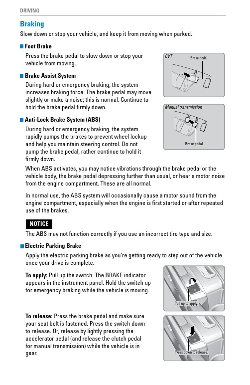
DRIVINGBraking Slow down or stop your vehicle, and keep it from moving when parked.Foot BrakePress the brake pedal to slow down or stop your vehicle from moving.Brake Assist SystemDuring hard or emergency braking, the system increases braking force. The brake pedal may move slightly or make a noise; this is normal. Continue to hold the brake pedal firmly down.Anti-Lock Brake System (ABS)During hard or emergency braking, the system rapidly pumps the brakes to prevent wheel lockup and help you maintain steering control. Do not pump the brake pedal, rather continue to hold it firmly down.When ABS activates, you may notice vibrations through the brake pedal or the vehicle body, the brake pedal depressing further than usual, or hear a motor noise from the engine compartment. These are all normal.In normal use, the ABS system will occasionally cause a motor sound from the engine compartment, especially when the engine is first started or after repeated use of the brakes.The ABS may not function correctly if you use an incorrect tire type and size. Electric Parking BrakeApply the electric parking brake as you’re getting ready to step out of the vehicle once your drive is complete.To apply: Pull up the switch. The BRAKE indicator appears in the instrument panel. Hold the switch up for emergency braking while the vehicle is moving.To release: Press the brake pedal and make sure your seat belt is fastened. Press the switch down to release. Or, release by lightly pressing the accelerator pedal (and release the clutch pedal for manual transmission) while the vehicle is in gear.Pull up to apply. Press down to release.DRIVINGAutomatic Brake HoldUse brake hold to make stop-and-go driving easier. It maintains rear brake hold even after the brake pedal is released. Make sure the vehicle is on and your seat belt is fastened when operating this feature.1.Press the BRAKE HOLD button behind the shift lever. The BRAKE HOLD indicator appears in the instrument panel.2.With the shift lever in Drive (D) or Neutral (N), press the brake pedal and come to a complete stop. The HOLD indicator appears, and brake hold is applied. Release the brake pedal.Press the accelerator pedal (or shift into a gear and release the clutch pedal for manual transmission) to cancel brake hold and start moving.To turn off brake hold:Press the brake pedal and press the BRAKE HOLD button again.Automatic brake hold cancels when:•Braking is applied for more than 10 minutes.•The electric parking brake is engaged.•The foot brake is pressed and the shift lever* is moved to Park or Reverse.•The engine stalls (manual transmission).•The driver’s seat belt is unfastened.•The engine is turned off.•There is a problem with the automatic brake hold system.DRIVINGVehicle Stability Assist® (VSA®)Also known as Electronic Stability Control (ESC), VSA helps to stabilize the vehicle during cornering if the vehicle turns more or less than what was intended. It assists in maintaining traction on slippery surfaces by regulating engine output and selectively applying the brakes.Turning VSA On or OffVSA is turned on every time you start the engine, Array even if you previously turned it off. If you turn VSAoff, your vehicle has normal braking and corneringability, but traction control will be less effective.Press and hold the VSA OFF button until youhear a beep to turn VSA on or off. The VSA OFFindicator appears when the system is off.When VSA is off, traction control stopsfunctioning, which may make it easier when tryingto free your vehicle if it is stuck in mud or snow.。
汽车刹车系统设计说明书
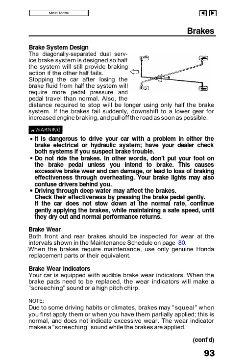
Brake System Design The diagonally-separated dual serv-ice brake system is designed so half the system will still provide braking action if the other half fails.Stopping the car after losing the brake fluid from half the system will require more pedal pressure and pedal travel than normal. Also, the distance required to stop will be longer using only half the brake system. If the brakes fail suddenly, downshift to a lower gear for increased engine braking, and pull off the road as soon as possible.It is dangerous to drive your car with a problem in either the brake electrical or hydraulic system; have your dealer check both systems if you suspect brake trouble.Do not ride the brakes. In other words, don't put your foot on the brake pedal unless you intend to brake. This causes excessive brake wear and can damage, or lead to loss of braking effectiveness through overheating. Your brake lights may also confuse drivers behind you.Driving through deep water may affect the brakes.Check their effectiveness by pressing the brake pedal gently.If the car does not stow down at the normal rate, continue gently applying the brakes, while maintaining a safe speed, until they dry out and normal performance returns.Brake WearBoth front and rear brakes should be inspected for wear at the intervals shown in the Maintenance Schedule on page 80.When the brakes require maintenance, use only genuine Honda replacement parts or their equivalent.Brake Wear Indicators Your car is equipped with audible brake wear indicators. When the brake pads need to be replaced, the wear indicators will make a "screeching" sound or a high pitch chirp.NOTE:Due to some driving habits or climates, brakes may "squeal" when you first apply them or when you have them partially applied; this is normal, and does not indicate excessive wear. The wear indicator makes a "screeching" sound while the brakes are applied.Brakes(cont'd)Brakes (cont'd)Brake FluidCheck the fluid level in the brakereservoir periodically; it should bebetween the MAX and MIN markson the reservoir.If the level is near the MIN mark, addfluid to raise it to the MAX mark. Donot overfill. Use only brake fluidmanufactured to DOT 3 or DOT 4specifications (see reservoir cap)from a sealed container. Follow themanufacturer's instructions printedon the can.NOTE:A low brake fluid level may be an indication of brake pad wear or of brake fluid leakage. You should have your brakes checked if the brake fluid level in the reservoir is low before re-filling it.CAUTION:The arrow on the reservoir cap must be pointing forward after the cap is installed. Make sure the brake warning switch wiring doesn't get caught between the cap and top edge of the reservoir.ANTI-LOCKBRAKE FLUID RESERVOIRAnti-lock Brake Fluid (SE)Check the fluid level in the Anti-lock brake reservoir periodically.To check, drive the car for a few minutes to equalize fluid pressure inthe system.The level should be between theMAX and MIN marks on thereservoir. If the level is near the MINmark, add fluid to raise it to theMAX mark.Do not overfill. Use only brake fluidmanufactured to DOT 3 or DOT 4specifications from a sealed container.Follow the manufacturer's instructions printed on the can.If the level is more than 10 mm (0.4 in) above the MAX mark, it may indicate a malfunction of Anti-lock brake system. Have an authorized Honda dealer check the system as soon as possible.MAXMINClutch Fluid (Manual Transmission)Check the fluid level in the clutch reservoir periodically; it should be between the MAX and MIN marks on the reservoir.If the level is near the MIN mark, add fluid to raise it to the MAX mark. Do not overfill. Use only brake fluid manufactured to DOT 3 or DOT 4specifications from a sealed con-tainer. Follow the manufacturer's in-structions printed on the can.NOTE:A low clutch fluid level may be an indication of clutch fluid leakage.You should have your clutch checked if the clutch fluid level in the reservoir is low.CLUTCH FLUIDRESERVOIRPower Steering The power steering on your car provides easy handling while parking and maneuvering in traffic, without loss of road "feel" at highway speeds. An engine-driven hydraulic pump provides full power assist at low speeds and decreasing assist as the car goes faster.CAUTION:If the power steering system should fail,or if the engine should stall, the car can still be steered. However, much greater effort will be required, particularly in sharp turns at low speed.NOTE:You may feel a slight clunk or knock when turning the wheel with the engine off. This is a normal condition due to the design of the system.Power Steering Fluid Check the power steering fluid level with the engine cold and the car parked on level ground. Make sure the fluid level is between the upper and tower marks on the reservoir. If the level has dropped close to or below the tower mark, check for leaks before adding fluid to the upper mark. Do not overfill.CAUTION:Use only genuine Honda power steering fluid. The use of other fluids such as A.T.F. or other manufacturer's power steering fluid will damage the system.RESERVOIR CAPUPPERLOWERAir and Fuel FiltersAir FilterReplace the air filter every 24 months or 30,000 miles (48,000 km),whichever comes first (more often in extremely dusty conditions).Loosen the attaching bolts, then remove the cover.Remove the air filter and replace it with a new filter. Reinstall the cover and tighten the bolts.Fuel FiltersThe fuel filter is located in the engine compartment, on the right center of the lower dashboard. It should be replaced at 60,000 miles (96,000 km) or 48 months whichever comes first, or any time you suspect contaminated gas may have clogged it.CAUTION:Because the fuel system is under pressure, the filter should be replaced only by a qualified Honda technician.BOLTSSpark plugs should be replaced every 24 months or 30,000 miles (48,000 km), whichever comes first.Recommended spark plugs:ZFR5F-11 (NGK) KJ16CR-L11 (ND)(for all normal driving)ZFR6F-11 (NGK) KJ20CR-L11 (ND)(for hot climates or continuous high speed driving)Keep hands away from the radiator fan. The fan may start automatically without warning and run for up to 15 minutes, even after the engine is turned off.CAUTION:Never use spark plugs with an improper heat range; they will adversely affect engine performance and durability.Replace plugs one at a time, so you don't get the wires mixed up.1. Clean any dirt from around the spark plug base.2. Disconnect the plug cap, then remove and discard the old plug.3. Check the gap of the new spark plug before installation.Plug gap should be:1.1 mm (0.04 in)4. Thread the new spark plug in by hand to prevent cross-threading.5. After the plug seats against the cylinder head, tighten 1/2 turn with a spark plug wrench to compress the washer.6. Reinstall the spark plug cap.CAUTION:The spark plugs must be securely tightened, but not overtightened.A plug that's too loose can get very hot and possibly damage the engine; one that's too tight could damage the threads in the cylinder head.Spark Plugs Thread in by hand.PLUG CAPWiper Blades For maximum visibility, replace worn or cracked wiper blades when you notice they do not wipe the windshield cleanly or smoothly.To Replace Worn-out Blades 1. Detach the blade assembly from the arm by pressing the lock tab in, then pushing the blade toward the base of the arm.2. Firmly grasp the end of the blade rubber and pull until the tabs are free of the metal support.3. Remove the metal retainers from the worn-out blade rubber and put them in a new blade rubber.4. Insert the new blade rubber from the opposite side of the blade tabs and position the tabs in the metal support.5. Reinstall the blade assembly on the wiper arm.Press LockTab inPushMETAL SUPPORTPull outTABSRETAINERS。
制动系统设计指南
制动系统的设计1.前言1.1适用范围1.2引用标准1.3轿车制动规范对制动系统制动性的总体要求1.4制动系统的设计方法1.5整车参数1.6设计期望值2 行车制动系统的设计2.1制动器总成的设计2.2人力制动系和伺服制动系2.3踏板总成的设计2.4传感器设计2.5 的设计3 应急制动及驻车制动的设计五、制动系统的设计1.前言1.1适用范围:本设计指南适用于在道路上行驶的汽车的制动系统1.2引用标准7258—1997 ******1.3轿车制动规范对制动系统制动性的总体要求汽车应设置足以使其减速、停车和驻车的制动系统。
设置对前、后轮分别操纵的行车制动装置。
应具有行车制动系。
汽车应具有应急制动功能和应具有驻车制动功能。
汽车行车制动、应急制动和驻车制动的各系统以某种方式相联,它们应保证当其中一个或两个系统的操纵机构的任何部件失效时(行车制动的操纵踏板、操纵连接杆件或制动阀的失效除外)仍具有应急制动功能。
制动系应经久耐用,不能因振动或冲击而损坏。
1.4制动系统的设计方法1.4.1制动系统开发流程1.4.2制动系统方案的确定1.4.3制动系统方案确定的顺序1.5整车参数1.5.1整车制动系统布置方案1.6设计期望值1.6.1制动能力汽车制动时,地面作用于车轮的切线力称为地面制动力,它是使汽车制动而减速行驶的外力。
在轮胎周缘克服制动器摩擦力矩所需的力称为制动器制动力。
地面制动力是滑动摩擦约束反力,其最大值受附着力的限制。
附着力FΦ与的关系为=FΦ=·Φ。
为地面垂直反作用力,Φ为轮胎—道路附着系数,其值受各种因素影响。
若不考虑制动过程中Φ值的变化,即设为一常值,则当制动踏板力或制动系压力上升到某一值,而地面制动力达最大值即等于附着力时,车轮将抱死不动而拖滑。
踏板力或制动系压力再增加,制动器制动力由于制动器摩擦力矩的增长,仍按直线关系继续上升,但是地面制动力达到附着力的值后就不再增加了。
制动过程中,这三种力的关系,如图1所示。
制动系统设计说明书
PDF 文件使用 "pdfFactory Pro" 试用版本创建
前轴荷:6500Kg
后轴荷:11500Kg
将相关参数代入制动系计算程序
得到:(以下所称标准均为中国汽车标准) ---------------制动过程模拟计算分析-------------
1.空载同步系数. 0.702951652069104 2.满载同步系数. 0.487450622408438 3.驻车制动力符合实验要求. 4.空载时制动力与轴荷比符合标准. 5.满载时制动力与轴荷比符合标准. 6.空载时前制动力与前轴荷比符合标准. 7.满载时前制动力与前轴荷比符合标准. 8.在初速度 30Km/h 情况下制动距离符合制动标准.
13.在初速度 60Km/h 情况下平均减速度符合 ECE 标准
14.上坡驻车角度. 28.301318090934
15.下坡驻车角度. 20.9464441425081
************************** 一.在 30Km/h 制动初速度下地面附着系数为:0.3,0.4,0.5,0.6,0.7 时的制动平均减速度: 2.23812423873325 2.76419706656638 3.21803852889667 3.61356932153392 3.96134893748075
六.结论
根据以上分析可以得出选用的制动系统制动力大小和前后分配符合本底盘的制动要求,并满 足制动法规。同时制动器的左右制动差要满足要求,如在实验中不能满足左右制动差要求请 对制动间隙进行调整。(左右轮制动力差与该轴左右轮中制动力大者之比对前轴应≤20%,对 后轴应≤24%)
制动系统设计指南

整车制动性能要求,确定制动 分解目标
制动配置、电子控制要求
以往历史问题清单
设计初期规避历史问题 DFMAE
制动力矩匹配
根据整车输入参数,制动力矩 满足整车在 0.8 路面附着系数路面 时的理论需求力矩,初步确定前后 制动器的规格,缸径、作用半径、 摩擦系数(0.35-0.45 之间)
1 范围
本规范规定了制动系统的设计流程、设计方法及技术要求。 本规范适用于公司液压制动系统配置车型制动系统的设计和开发。
2 规范性引用文件
GB 7258-2012 机动车安全运行技术条件。 GB 12676-2014 商用车辆和挂车制动系统技术要求及试验方法。 GB 21670-2008 乘用车制动系统技术要求及试验方法。 GBT 13594-2003 汽车和挂车防抱制动性能和试验方法 ECER13-09,ECER13H-00 欧洲法规 FMVSS 105、FMVSS 126 美国法规
II
前言
为保证制动系统设计符合国家及行业标准,根据***公司要求规定,特制定制动系统设计指南,作 为设计、组织生产的依据。本标准规定了制动系统设计规范,适用于***公司各种制动系统设计。同时 在格式和内容的编排上均符合 GB/T 1.1-2000 和 GB/T 1.2-2002 的规定。
1
制动系统设计规范
b)、制动效能的恒定性,即抗热衰退和抗水衰退; c)、制动的稳定性,即制动时汽车不发生跑偏、侧滑以及失去转向能力的性能;
4 制动系统开发流程
4.1 开发工作及要求
序号 阶段
开发流程
表 1 制动阶段性工作及设计要求
具体事宜
基本技术要求及注意事项
1. P1
制动系统设计规范精选全文完整版

可编辑修改精选全文完整版一、国标要求1、GB 12676-1999《汽车制动系统结构、性能和试验方法》2、GB 13594-2003《机动车和挂车防抱制动性能和试验方法》3、GB 7258-1997《机动车运行安全技术条件》二、整车基本参数及样车制动系统主要参数整车基本参数样车制动系统主要参数三、计算1. 前、后制动器制动力分配1.1 地面对前、后车轮的法向反作用力 公式:gz h dt du mGb L F +=1 ………………………………(1) gz h dt du mGa L F -=2 (2)参数:1z F ——地面对前轮的法向反作用力,N ;2z F ——地面对后轮的法向反作用力,N ;G ——汽车重力,N ;b ——汽车质心至后轴中心线的水平距离,m ;a ——汽车质心至前轴中心线的距离,m 。
m ——汽车质量,kg ;gh ——汽车质心高度,m ;L ——轴距,m ;dt du——汽车减速度,m/s 2四、制动器的结构方案分析制动器有摩擦式、液力式和电磁式等几种。
电磁式制动器虽有作用滞后小、易于连接且接头可靠等优点,但因成本高而只在一部分重型汽车上用来做车轮制动器或缓速器。
液力式制动器只用作缓速器。
目前广泛使用的仍为摩擦式制动器。
摩擦式制动器按摩擦副结构形式不同,分为鼓式、盘式和带式三种。
带式只用作中央制动器。
一、鼓式制动器鼓式制动器分为领从蹄式、双领蹄式、双向双领蹄式、双从蹄式、单向增力式、双向增力式等几种,见图la ~f 。
不同形式鼓式制动器的主要区别有:①蹄片固定支点的数量和位置不同。
②张开装置的形式与数量不同。
③制动时两块蹄片之间有无相互作用。
因蹄片的固定支点和张开力位置不同,使不同形式鼓式制动器的领、从蹄数量有差别,并使制动效能不同。
制动器在单位输入压力或力的作用下所输出的力或力矩,称为制动器效能。
在评比不同形式制动器的效能时,常用一种称为制动器效能因数的无因次指标。
制动器效能因数的定义为,在制动鼓或制动盘的作用半径R 上所得到的摩擦力(RM μ)与输入力0F 之比,即RF M K 0μ=式中,K 为制动器效能因数;μM 为制动器输出的制动力矩。
制动系统设计说明书
摘要国内汽车市场迅速发展,而轿车是汽车发展的方向。
然而随着汽车保有量的增加,带来的安全问题也越来越引起人们的注意,而制动系统则是汽车主动安全的重要系统之一。
因此,如何开发出高性能的制动系统,为安全行驶提供保障是我们要解决的主要问题。
另外,随着汽车市场竞争的加剧,如何缩短产品开发周期、提高设计效率,降低成本等,提高产品的市场竞争力,已经成为企业成功的关键。
本说明书主要介绍了鼓式制动系统的设计。
首先介绍了汽车制动系统的发展、结构、分类。
除此之外,它还介绍了制动器、制动主缸的设计计算,主要部件的参数选择。
关键字:制动;鼓式制动器;AbstractThe rapid development of the domestic vehicle market, saloon car is an important tendency of vehicle. However, with increasing of vehicle, security issues are arising from increasingly attracting attention, the braking system is one of important system of active safety. Therefore, how to design a high-performance braking system, to provide protection for safe driving is the main problem we must solve. In addition, with increasing competition of vehicle market, how to shorten the product development cycle, to improve design efficiency and to lower costs, to improve the market competitiveness of products, and has become a key to success of enterprises.This paper mainly introduces the design of braking system. Fist of all, braking system’s development, structure and category are shown. Besides, this paper also introduces the designing process of rear brake, braking cylinder, parameter’s choice of main components braking and channel settings.Key words: braking; brake drum;第1章绪论 (1)1.1 制动系统设计的意义 (1)1.2 制动系统研究现状 (1)1.3 本次制动系统应达到的目标 (2)1.4 本次制动系统设计要求 (2)第2章鼓式制动系统分析 ..................................................... 错误!未定义书签。
制动部分设计指南
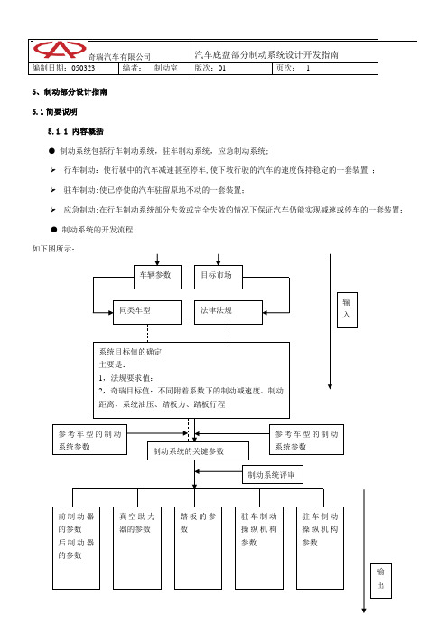
编制日期:050323 编者:制动室版次:01 页次:- 1 -5、制动部分设计指南5.1简要说明5.1.1 内容概括●制动系统包括行车制动系统,驻车制动系统,应急制动系统;➢行车制动:使行驶中的汽车减速甚至停车,使下坡行驶的汽车的速度保持稳定的一套装置;➢驻车制动:使已停使的汽车驻留原地不动的一套装置;➢应急制动:在行车制动系统部分失效或完全失效的情况下保证汽车仍能实现减速或停车的一套装置;●制动系统的开发流程:车辆参数目标市场同类车型法律法规系统目标值的确定主要是:1,法规要求值:2,奇瑞目标值:不同附着系数下的制动减速度、制动距离、系统油压、踏板力、踏板行程参考车型的制动系统参数制动系统的关键参数前制动器的参数后制动器的参数真空助力器的参数踏板的参数驻车制动操纵机构参数驻车制动操纵机构参数参考车型的制动系统参数制动系统评审输入输出编制日期:050323 编者:制动室版次:01 页次:- 2 -5.1.2适用范围适用于所有奇瑞公司所开发的车型.5.1.3 设计目的合理设计汽车的制动系统,其目的在于:在满足国家法规要求的同时,具有良好的舒适性,满足用户的要求.5.1.4 零件结构图制动系统主要分为三部分:1行车制动系统:包括基础制动器,真空助力器,制动管路,踏板,2.驻车制动系统,包括驻车操纵机构总成,制动拉索,驻车制动器3.压力调节装置包括包括ABS控制器总成或比例阀,ABS传感器等,5.2设计构想5.2.1 设计原则5.2.1.1 制动系统的功能要求●行车制动必须保证驾驶员在行车过程中能控制机动车安全、有效地减速和停车。
行车制动必须是可控制的,且必须保证驾驶员在其座位上双手无须离开方向盘(或方向把)就能实现制动; 驻车制动应能使机动车即使在没有驾驶员的情况下,也能停在上、下坡道上。
驾驶员必须在座位上就可以实现驻车制动。
编制日期:050323 编者:制动室版次:01 页次:- 3 -●制动效能要满足法规要求●有良好的制动稳定性●驾驶感好(包括踏板力,踏板行程)●有良好的热衰退性能(通过AMS试验来验证,详见试验部分)5.2.1.2 制动系统的顾客要求在满足制动性能的前提下,还应该满足舒适性要求,如:操作方便,行车制动在产生最大制动效能时的踏板力,对于乘用车不应大于230N ;手握力不应大于 250 N,除了这些力的要求,尽量避免有制动点头,制动时摩擦片尖叫等不良现象,同时在行车制动系统失效的情况下,还应具有应急制动的功能.5.2.1.3 制动系统的性能要求制动系统性能要满足法规GB/T12676要求,GB/T12676等同于欧洲法规ECER13-09,ECER13H-00及美国法规FMVSS 1355.2.2 制动系统设计计算5.2.2.1 ●决定制动系统关键参数的因素:详见下表决定制动系统参数的整车调查表Laden Weight [kg] : 满载质量Laden Weight perc.front [%] :满载前轴轴荷比重Laden Height of c.g. [mm] :满载重心高度(hg)Unladen weight [kg] : (kerb Weight)空载质量Unladen Weight perc. Front [%] :空载前轴轴荷比重Unladen height of c.g. [mm] :空载重心高度Wheelbase[mm] :轴距Split F/R, X, L, HI, or HH):管路布置型式奇瑞汽车有限公司汽车底盘部分制动系统设计开发指南编制日期:050323 编者:制动室版次:01 页次:- 4 -Maximum axle load front [kg] :前轴最大轴载Maximum axle load rear [kg] :后轴最大轴载Maximum speed [km/h] :最高车型Engine Power [ kW] :发动机功率Engine stroke volume [ccm]:发动机排量Laden acceleration 0 to 100 km/h [s] :满载车速从0到100的加速时间Half laden acceleration 80km/h to 90% vmax [s] :半载车速从80到最大车速的90%的加速时间Power Transmission (Front, Rear or 4 wheels) :驱动型式Tire rolling radius front [mm] : 前轮滚动半径Tire rolling radius rear [mm] :后轮滚动半径Rim Size [in] :轮辋规格Tire size front : 前轮胎规格Tire size rear :后轮胎规格●计算过程汽车制动时,地面作用于车轮的切线力称为地面制动力F xb,它是使汽车制动而减速行驶的外力。
汽车制动系统设计开发流程教材(PDF 44页)

Fbf m(gB ugh) u ( A B)
Fbr m(gA ugh)u (A B)
对同一车辆来说,上两式中,只有u为变量,取不同的u值便可得 到不同Fbf和Fbr值。这便是理想制动力分配曲线,如下页
F 线组是前轮抱死时前后轮地面制动 力的变化关系
h
A
B
Ff mg B ma h (A B) (A B)
Fr mg A ma h (A B) (A B)
a Fb m
假设制动时车轮完全抱死,整车制动力就等于地面附着力
Fbf u Ff Fbr u Fr
u 为地面提供的附着系数
Fb u mg Fbf Fbr Fb
分析可发现,将制动钳后置在制动时施加在轴承上的径 向载荷远小于制动钳前置的情况。
为了减小簧下质量,在赛车上将制动钳与制动盘移至传动轴 内球笼一侧,从而由簧下质量变为簧载质量。这样的好处多方面 的。可以用小的减振器,刚度小的弹簧…
制动盘的布置位置
理想情况是轮胎中线线及制动盘中心还有轴承中心在 y方向重合,这样在制动时在轴承及轮毂上就不会产 生附加的弯矩。
后轮地面制动 力增量(负值)
后轮制动器制 动力增量
前轮制动器制 动力亦地面制
动力增量
R线组
实际制动力分配曲线
关于制动系统理 论,如果在此分析将 占用很大的篇幅,今 后将在制动系统设计 指南中详细分析,在 此就不赘述了!
理想制动力分配曲线
F线组
在附着系数等于0.5的路面上制动,随着制动器 制动力的增加,地面制动力随之上升,当达到实际制 动力与理想制动力的焦点时,前后制动器同时抱死。 此后制动器制动力再增加已无意义。
汽车制动系统设计开发流程
- 1、下载文档前请自行甄别文档内容的完整性,平台不提供额外的编辑、内容补充、找答案等附加服务。
- 2、"仅部分预览"的文档,不可在线预览部分如存在完整性等问题,可反馈申请退款(可完整预览的文档不适用该条件!)。
- 3、如文档侵犯您的权益,请联系客服反馈,我们会尽快为您处理(人工客服工作时间:9:00-18:30)。
总体上写得不错,需要进一步改进的建议如下:
1.主要零部件的典型结构图。
2.分泵、总泵、吊挂助力器和阀等试验验证与试制验证的方法与标准(结合参考上次L项目验证计划)细化与补充。
3.分泵、总泵、吊挂助力器和阀的DFMEA分析的主要内容。
3.做到图文并茂,无经验的年轻的设计人员(《设计手册》主要读者)一看就明白。
3.3.6制动管路的布置:
首先以不与其它零部件干涉为前提,应尽量理顺;其次各管路的结构应合理,尤其是管路两端在整车行驶过程中有相对运动的件应考虑吸震方案,必要时采用软管连接;另外,在进行管路布置时应考虑管子的卡固,在空间允许的前提下管卡子的间隔以500~600mm为佳,当然在局部障碍部位可能要密一些。
真空助力器的直接作用在于降低制动踏板力,当制动踏板力太大时,仅依靠人的输入力(按照标准要求人的最大输入力不得大于700N)可能不足以使整车完全制动,而利用真空对助力器内橡胶膜片及反馈盘的作用可以成数倍(取决于真空助力器的助力比)地放大制动踏板的输入力,即增大制动总泵活塞的输入力,从而增大制动管路的压力。当然真空助力器助力比的选取应合适,助力比太大易使驾驶员失去踏板感,而太小又使人在制动过程中感到吃力,且对于一定规格的助力器来说,助力器的助力比越大,其最大输出拐点越低,这就容易造成整个制动过程在初期省力,但在后期特废力,严重时也会刹不住车,故真空助力器助力比的选取以使制动踏板力调整适当为宜。另当某一规格的助力器对整车制动踏板力的调整不能满足要求且适当调整助力比仍不能达到要求时应更换助力器的规格。
3.3制动系统各总成零部件在设计和布置过程中的注意事项:
3.3.1制动器总成:
优先采用社会成熟资源,但在与整车实际应用时应考察制动器的效能、制动底板、制动蹄铁、制动鼓的刚性与整车的符合性。
3.3.2制动总泵:
应严格控制总泵的空行程、建压行程和建压曲线,一般总泵每腔的空行程以不大于1.5mm,在输出口输出压力达0.4Mpa时总泵活塞推杆的行程不得大于4mm(一般0.4Mpa的管路压力可以消除制动蹄与制动鼓之间的间隙),总泵的建压曲线越陡越好,不能过于平坦,否则会造成制动踏板感发绵、发软。
3.1.1.2制动器结构型式的选型原则:
根据整车档次、使用地区、用户群体等确定制动器的结构型式;
系统类型
制动器结构型式
制动器特点
适用整车工作情况
备注
液压制动系统
盘式
具有优良的热稳定性和水稳定性,适应于高速的需求,但由于其制动效能低(需要输入较高的液压),制动液的工作温度较高,且价格也较高
广泛用于中高档车上
3.1.2真空助力器带制动总泵总成
3.1.2.1制动总泵的选取原则:
制动总泵的选取主要取决于制动分泵,在制动器间隙合适的情况下,其直径的选取将直接引响制动踏板的行程,对于单分泵制动器的系统,一般以总泵的直径与后制动器直径相当为宜,而对于双分泵制动器的系统其总泵助力器的选用原则:
3.2.2.4制动距离:
根据相关标准的要求应与其符合,必要时按法规要求在规定的制动踏板下进行部分管路失效计算;
3.2.2.5制动器的磨损容量和热容量:
一般用磨擦片的比能量耗散率[每单位衬片(衬块)磨擦面积的每单位时间耗散的能量]、比磨擦力[每单位衬片(衬块)磨擦面积的制动器的磨擦力]来衡量制动器的热容量和磨损容量。鼓式制动器的热容量以不大于1.8w/mm2,盘式制动器不大于6w/mm2,磨损容量不大于0.48N/mm2为宜。
领从蹄式
制动过程较稳定,构造简单,价格也比较低,但制动效能较低
适用范围较广,一般用于后制动器,与盘式或双领蹄式制动器配合。
双领蹄式/双向双领蹄式
制动过程较稳定,价格适中,但制动效能也比较适中
广泛应用于各类中高档汽车中,尤其是轻卡新产品
双从蹄式
虽然其结构简单、稳定性好,但其制动效能太低
在汽车产品中较少应用
5.闭环反馈设计验证
主要根据性能试验结果对制动系统各零部件的匹配进行重新调整(必要时),当然在重新匹配验证时要求对整车参数进行准确测定。
附:
XXXXXXX车型制动系统设计计算书
1.结构简述
2.整车参数
轴距离L(mm)
参数
空载
满载
质心距前轴a (mm)
质心高hg (mm)
总质量Ga (kg)
前轴负荷G1 (kg)
效能较低双领蹄式制动过程较稳定价格适广泛应用于各类中高档汽车中尤双向双领蹄中但制动效能也比较适中其是轻卡新产品式双从蹄式虽然其结构简单稳定性在汽车产品中较少应用好但其制动效能太低冲压底板渐开线凸轮价格低廉但制动底板的刚性相对较弱且凸轮与制动蹄铁之间为滑动摩擦时间久现主要用于经济型汽车或农用车中了或润滑不良的情况下在接触面易形成沟槽或浊点气压制领从蹄式引起制动蹄回位不良等问动系统题铸造底板s凸轮价格较高制动底板的刚性较强凸轮与制动蹄铁之间为滚广泛用于各类气制动系统的车型中动摩擦整个制动过程相对较为稳定3113制动器直径的选型原则
2.2根据车型提供的整车参数,结合各项强制法规的要求,初步分析各所选制动零部件与整车匹配的合理性;
2.3根据强制法规的要求,制定试验方案进一步验证整车制动系统匹配和各制动元件选型的合理性。
3.设计方案初步规划
3.1各主要零部件的选型及相关注意事项:
3.1.1制动器总成
3.1.1.1通过对所开发车型与已开发同类车型(或标杆车)的比较,初步确定系统各零部件的型式、结构和相关参数,而单纯从整车对制动力的需求方面来说,制动器的制动力越大越好,但由于制动器所产生的制动力与制动器的结构型式、制动器直径、制动器的分泵直径、制动器摩擦副的相对摩擦系数、制动管路压力等等因素有关,故在选取时应遵循以下原则;
3.1.1.5制动器分泵直径的选型和确定:
在上述参数选定以后,根据整车所需的各轴制动力来确定制动器分泵的直径。对于单个制动器而言,制动器所产生的制动力与制动分泵活塞的有效面积(直径的平方——液压制动器)成正比,在选取过程中应兼顾国家标准规格(为提高零部件资源的通用性,国家对制动总、分泵的直径的规格制定了相关标准)和社会成熟资源,液压制动器的分泵直径最大不超过32mm。
3.2.2分析计算过程中的相关注意事项:
3.2.2.1整车基本参数应尽可能地准确,尤其是空、满(超)载质心的位置;
3.2.2.2制动踏板的行程:
根据制动系统各部分总的杠杆比情况一般不得大于制动踏板总行程的75%;
3.2.2.3制动踏板力:
一般情况下制动踏板力不宜过大,在0.8制动强度下整车的制动踏板力轻卡以不大于250N、小卡、微卡以不大于200N为宜;
广泛用于各类气制动系统的车型中
3.1.1.3制动器直径的选型原则:
由于制动器的直径与轮辋直径有关,在选型时应根据整车布置及轮辋的要求,考虑制动鼓的散热问题,一般制动鼓与轮辋的间隙应不小于10mm,否则会导致制动器散热不良,引起制动鼓早期龟裂、制动衬片烧结、炭化,大大降低制动器的制动效能;另外,制动器与轮辋的间隙太小,制动过程所产生的热量也将大量传导至轮辋上,对轮胎不利。
3.1.1.4制动器衬片摩擦系数的确定:
由于制动器衬片的摩擦系数是决定制动器制动力的主要原因之一,在同型、同规格的制动器中,制动衬片的摩擦系数越高,制动器所产生的制动力越大,但对于不同结构的制动器来说,并不是摩擦系数越高越好,摩擦系数太高对制动鼓(或盘)的磨损也越大,且对于双向自增力式制动器,摩擦系数越高,制动过程越粗暴,对制动底板、制动蹄铁、制动鼓的刚性要求越高,否则在制动过程中越易产生制动器颤动、整车发抖的现象,故对于摩擦系数的选取根据本人的经验建议:双向自增力式制动器的取0.38左右,其它结构型式的制动器取0.45~0.5左右,盘式制动器取0.35左右。
制动系统一般可分为四种,即行车制动系、应急制动系(也称第二制动系)、驻车制动系和辅助制动系统(一般用于山区、矿山下长坡时)。
各种制动系统一般有执行机构和控制机构两个部分组成。其执行机构是产生阻碍车辆的运动或运动趋势的力(制动力)的部件,通常包括制动鼓、制动蹄、制动盘、制动钳和制动轮缸等;其控制机构是为适应所需制动力而进行操纵控制、供能、调节制动力、传递制动能量的部件,一般包括助力器、踏板、制动主缸、储油杯、真空泵、真空罐、比例阀、ABS、制动管路和报警装置等,有的还包括具有压力保护和故障诊断功能的部件。在其控制机构中如果按其制动能量的传输方式制动系统又可分为:机械式、液压式、气压式和电磁式(同时采用两种以上传能方式的制动系统可称为组合式制动系统,如气顶油等)。
4.试验验证
4.1试验目的:通过性能试验验证系统的配置与整车及法规的符合性;通过可靠性试验以验证系统各零部件的工作可靠性。
4.2试验前提:在试验前一定要将整个系统按规范进行调整完毕,即:管路系统无空气、踏板的自由行程(一般不大于15mm)符合要求、制动器的间隙合适等。
4.3试验标准和方法:按GB12676强制标准所要求的制动系统性能要求和试验方法进行性能试验验证。
对制动液的要求高,否则制动液会气化形成气阻
双向自增力式
价格低廉、制动效能高但制动过程较粗暴、稳定性较差,且效能太高易发生制动器自锁
在国外尤其是美国、澳大利亚等较多地用于大型高速轿车中,但由于国内在制造工艺、生产水平等方面存在一定的问题,该类制动器不适合高速车辆配置;普遍用于农村或城乡结合带且超载较为频繁的车辆上
前轴质量分配%
后轴负荷G2 (kg)
后轴质量分配%
以上参数根据车型所提供(确定)的整车输入参数而定。
3.汽车动轴荷分配计算:
3.1动轴荷计算:
当汽车以一定的制动减速度jt进行制动时,由于减速度而产生的惯性力,使轴荷分配相应改变:(下表所列为不同制动强度下各轴的轴荷)
3.1.1.6前后制动器制动分泵的选取、分配原则:
从各方面的调查分析,对于一般的驾驶员来说,在正常行车的过程中实施制动的概率分布如下:制动强度在0.25以下的约占95%左右,在0.5以上的仅占0.1%。这一统计数据表明通常的制动都是在小制动减速度下进行,且此时各轴的车轮均未出现抱死现象,即制动衬片与制动鼓之间一直处于滑动摩擦阶段,而此时整个制动系统的管路压力一样,对于同样结构的制动器,如果分泵活塞直径大,则制动器产生的制动力就大,从而导致制动衬片的磨损加大,因此,在确定前后制动分泵直径时,最佳原则时前后制动器分泵直径相等或后分泵比前分泵稍小,以确保前后制动器在正常情况下同步磨损。当然,当前后制动分泵直径相等或相差不大时,在实施较大制动强度的制动时易出现后轮先抱死甩尾,故在采取此种分配方式时必须增加阀类元件调节后管路的压力,以防止后轮先抱死。
