完美公司奖金制度6000PV以上优惠18%
TJNB6000变频器使用说明书2017版.pdf

目录第一章安全注意事项与检查 (5)1.1 安全注意事项 (5)1.2 开箱之后检查 (6)第二章安装及配线 (7)2.1 使用环境 (7)2.2 安装方向与空间 (7)2.3 配线 (8)2.4 主回路端子 (9)2.5 控制回路端子 (9)2.6 接线注意事项 (10)2.7 备用电路 (10)第三章操作键盘 (11)3.1 按键说明及功能: (11)3.2 键盘尺寸: (13)3.3 参数设定方式 (14)第四章功能参数一览表 (15)4.1控制与显示 (15)4.2输入输出端子 (17)4.3基本运行参数 (19)4.4扩展及保护功能 (20)4.6跳跃频率 (21)4.7自设定V/F曲线功能 (21)4.8 PID控制 (22)4.9程序运行 (23)4.10摆频运行 (24)4.11故障查询功能 (25)4.12变频器状态及系统参数 (26)第五章功能参数说明 (28)5.1控制与显示 (28)5.2输入输出端子 (34)5.3基本运行参数 (40)5.4扩展及保护功能 (48)5.5直流制动功能 (52)5.6跳跃频率 (53)5.7自设定V/F曲线功能 (54)5.8 PID控制 (57)5.9程序运行 (60)5.10摆频运行 (63)5.11故障查询 (64)5.12变频器状态及系统参数 (64)六、保护功能 (67)6.2 短路保护 (69)6.3输出缺相保护 (69)6.4 变频器过热保护 (69)6.5 过电压保护 (69)6.6 欠电压保护 (69)6.7参数设置错误 (69)6.8 变频器外部故障 (69)第七章异常诊断与处理 (70)第八章保养与检修 (71)8.1 检查与保养 (71)8.2 必需定期更换的器件 (72)8.3 储存与保管 (72)8.4 测量与判断 (72)第九章标准规范 (73)9.1 TJNB6000系列各种规格的额定输出电流表 (73)9.2标准规范 (76)9.3 安装尺寸 (77)第十章主回路图与附件 (78)10.1主回路及外接附件图 (78)10.2制动单元及制动电阻 (79)10.3电抗器 (80)第十一章品质保证 (82)第一章 安全注意事项与检查1.1 安全注意事项● 绝不可将交流电源接至变频器输出端U、V、W等端子。
PowerFlex 中壓交流變頻器選型指南说明书

PowerFlex 中壓交流變頻器型號編號 6000G 、6000T 、7000A 、7000 與 7000LPowerFlex 中壓交流變頻器 產品選型指南內容主題頁碼最新消息2PowerFlex 中壓變頻器的優點3為您的應用選擇適合的 PowerFlex 變頻器4中壓變頻器選型流程圖6PowerFlex 中壓變頻器比較7一般應用負載扭矩系列9PowerFlex 6000T 中壓 交流變頻器11PowerFlex 7000 中壓交流變頻器15變頻器選項20其他資源23最新消息PowerFlex® 6000T 的增強功能包括:高速應用PowerFlex 6000T 可在所有控制模式下,以固有的方式控制高達 120 Hz 輸出頻率的高速應用。
已啟用 CIP SecurityPowerFlex 6000T 已啟用 CIP Security™,可支援深度防禦策略並保護⾃⾝不受所有網路資安事件影響。
擴充輸入電壓功能PowerFlex 6000T A 框架 IEC 變頻器的輸出電壓額定值為 3.3 和 4.16 kV,現在可提供高達 13.8 kV 的主要輸入功能。
選購的 RealSine 解決方案可用範圍 2.4…4.16 kV 且最高 215 A,無需變更變頻器專用變壓器的⼆次繞組數量,每個繞組經過特別的相位偏移分別可達到 54 脈衝或 72 脈衝,在這個電壓範圍下,其他傳統的設計只能達到 18 脈衝或 24 脈衝。
選購的 RealSine™ 解決方案在輸入總諧波電流失真 (THDi) 方面可改善高達 30%。
此新設計不需要額外的硬體,也不會影響變頻器的佔地面積。
減少佔地面積的 A 框架額定電壓為 6 與 6.6 kV 的 PowerFlex 6000T IEC 變頻器現在提供最高可達 215 A 的一體式設計。
這些小巧的變頻器可在不變更變頻器尺⼨下提供最高可達 13.8 kV 的一次側電壓。
NTP18N06L中文资料

NTP18N06L, NTB18N06L Power MOSFET 15 Amps, 60 Volts,Logic LevelN−Channel TO−220 and D 2PAKDesigned for low voltage, high speed switching applications in power supplies, converters and power motor controls and bridge circuits.Typical Applications•Power Supplies •Converters•Power Motor Controls •Bridge CircuitsMAXIMUM RATINGS (T= 25°C unless otherwise noted)MARKING DIAGRAMS & PIN ASSIGNMENTSNTx18N06L= Device Code x = B or PLL= Location Code Y = YearWW= Work Week4DrainDrain NTx18N06L LLYWW1Gate 3Source4Drain2DrainSee detailed ordering and shipping information in the package dimensions section on page 10 of this data sheet.ORDERING INFORMATIONELECTRICAL CHARACTERISTICS(T= 25°C unless otherwise noted)2.Switching characteristics are independent of operating junction temperature.Figure 5. On−Resistance Variation withTemperature T J , JUNCTION TEMPERATURE (°C)V DS , DRAIN−TO−SOURCE VOLTAGE (VOLTS)Figure 6. Drain−to−Source Leakage Currentversus VoltageI D , D R A I N C U R R E N T (A M P S )R D S (o n ), D R A I N −T O −S O U R C E R E S I S T A N C E (W )R D S (o n ), D R A I N −T O −S O U R C E R E S I S T A N C E (N O R M A L I Z E D )POWER MOSFET SWITCHINGSwitching behavior is most easily modeled and predictedby recognizing that the power MOSFET is charge controlled. The lengths of various switching intervals (D t)are determined by how fast the FET input capacitance can be charged by current from the generator.The published capacitance data is difficult to use forcalculating rise and fall because drain−gate capacitancevaries greatly with applied voltage. Accordingly, gatecharge data is used. In most cases, a satisfactory estimate ofaverage input current (I G(A V)) can be made from arudimentary analysis of the drive circuit so thatt = Q/I G(A V)During the rise and fall time interval when switching aresistive load, V GS remains virtually constant at a levelknown as the plateau voltage, V SGP . Therefore, rise and falltimes may be approximated by the following:t r = Q 2 x R G /(V GG − V GSP )t f = Q 2 x R G /V GSPwhereV GG = the gate drive voltage, which varies from zero to V GGR G = the gate drive resistance and Q 2 and V GSP are read from the gate charge curve.During the turn−on and turn−off delay times, gate current isnot constant. The simplest calculation uses appropriatevalues from the capacitance curves in a standard equation forvoltage change in an RC network. The equations are:t d(on) = R G C iss In [V GG /(V GG − V GSP )]t d(off) = R G C iss In (V GG /V GSP )The capacitance (C iss ) is read from the capacitance curve at a voltage corresponding to the off−state condition when calculating t d(on) and is read at a voltage corresponding to the on−state when calculating t d(off).At high switching speeds, parasitic circuit elementscomplicate the analysis. The inductance of the MOSFET source lead, inside the package and in the circuit wiring which is common to both the drain and gate current paths,produces a voltage at the source which reduces the gate drive current. The voltage is determined by Ldi/dt, but since di/dt is a function of drain current, the mathematical solution is complex. The MOSFET output capacitance alsocomplicates the mathematics. And finally, MOSFETs have finite internal gate resistance which effectively adds to the resistance of the driving source, but the internal resistance is difficult to measure and, consequently, is not specified.The resistive switching time variation versus gate resistance (Figure 9) shows how typical switching performance is affected by the parasitic circuit elements. Ifthe parasitics were not present, the slope of the curves would maintain a value of unity regardless of the switching speed.The circuit used to obtain the data is constructed to minimize common inductance in the drain and gate circuit loops andis believed readily achievable with board mounted components. Most power electronic loads are inductive; thedata in the figure is taken with a resistive load, which approximates an optimally snubbed inductive load. Power MOSFETs may be safely operated into an inductive load;however, snubbing reduces switching losses.GATE−TO−SOURCE OR DRAIN−TO−SOURCE VOLTAGE (VOLTS)C , C A P A C I T A N C E (p F )Figure 7. Capacitance VariationV SD , SOURCE−TO−DRAIN VOLTAGE (VOLTS)Figure 10. Diode Forward Voltage versus CurrentV G S , G A T E −T O −S O U R C E V O L T A G E (V O L T S )SAFE OPERATING AREAThe Forward Biased Safe Operating Area curves define the maximum simultaneous drain−to−source voltage and drain current that a transistor can handle safely when it is forward biased. Curves are based upon maximum peak junction temperature and a case temperature (T C ) of 25°C.Peak repetitive pulsed power limits are determined by using the thermal response data in conjunction with the procedures discussed in AN569, “Transient Thermal Resistance −General Data and Its Use.”Switching between the off−state and the on−state may traverse any load line provided neither rated peak current (I DM ) nor rated voltage (V DSS ) is exceeded and the transition time (t r ,t f ) do not exceed 10 m s. In addition the total power averaged over a complete switching cycle must not exceed (T J(MAX) − T C )/(R q JC ).A Power MOSFET designated E−FET can be safely used in switching circuits with unclamped inductive loads. Forreliable operation, the stored energy from circuit inductance dissipated in the transistor while in avalanche must be less than the rated limit and adjusted for operating conditions differing from those specified. Although industry practice is to rate in terms of energy, avalanche energy capability is not a constant. The energy rating decreases non−linearly with an increase of peak current in avalanche and peak junction temperature.Although many E−FETs can withstand the stress of drain−to−source avalanche at currents up to rated pulsed current (I DM ), the energy rating is specified at rated continuous current (I D ), in accordance with industry custom.The energy rating must be derated for temperature as shown in the accompanying graph (Figure 12). Maximum energy at currents below rated continuous I D can safely be assumed to equal the values indicated.SAFE OPERATING AREAFigure 11. Maximum Rated Forward BiasedSafe Operating Areat, TIME (s)0.11.00.01T J , STARTING JUNCTION TEMPERATURE (°C)E Figure 12. Maximum Avalanche Energy versusStarting Junction TemperatureV DS , DRAIN−TO−SOURCE VOLTAGE (VOLTS)Figure 13. Thermal Response1100I D , D R A I N C U R R E N T (A M P S )0.110Figure 14. Diode Reverse Recovery WaveformTIMEr (t ), T R A N S I E N T T H E R M A L R E S I S T A N C EINFORMATION FOR USING THE D2PAK SURFACE MOUNT PACKAGE RECOMMENDED FOOTPRINT FOR SURFACE MOUNTED APPLICATIONSSurface mount board layout is a critical portion of the total design. The footprint for the semiconductor packages must be the correct size to ensure proper solder connection interface between the board and the package. With the correct pad geometry, the packages will self align when subjected to a solder reflow process.SOLDER STENCIL GUIDELINESPrior to placing surface mount components onto a printed circuit board, solder paste must be applied to the pads. Solder stencils are used to screen the optimum amount. These stencils are typically 0.008 inches thick and may be made of brass or stainless steel. For packages such as the SC−59, SC−70/SOT−323, SOD−123, SOT−23, SOT−143, SOT−223, SO−8, SO−14, SO−16, and SMB/SMC diode packages, the stencil opening should be the same as the pad size or a 1:1 registration. This is not the case with the DPAK and D2PAK packages. If one uses a 1:1 opening to screen solder onto the drain pad, misalignment and/or “tombstoning” may occur due to an excess of solder. For these two packages, the opening in the stencil for the paste should be approximately 50% of the tab area. The opening for the leads is still a 1:1 registration. Figure 15 shows a typical stencil for the DPAK and D2PAK packages. The pattern of the opening in the stencil for the drain pad is not critical as long as it allows approximately 50% of the pad to be covered with paste.Figure 15. Typical Stencil for DPAK andD2PAK PackagesSOLDER PASTEOPENINGSSTENCILSOLDERING PRECAUTIONSThe melting temperature of solder is higher than the rated temperature of the device. When the entire device is heated to a high temperature, failure to complete soldering within a short time could result in device failure. Therefore, the following items should always be observed in order to minimize the thermal stress to which the devices are subjected.•Always preheat the device.•The delta temperature between the preheat and soldering should be 100°C or less.*•When preheating and soldering, the temperature of the leads and the case must not exceed the maximum temperature ratings as shown on the data sheet. When using infrared heating with the reflow soldering method, the difference shall be a maximum of 10°C.•The soldering temperature and time shall not exceed 260°C for more than 10 seconds.•When shifting from preheating to soldering, the maximum temperature gradient shall be 5°C or less.•After soldering has been completed, the device should be allowed to cool naturally for at least three minutes.Gradual cooling should be used as the use of forced cooling will increase the temperature gradient and result in latent failure due to mechanical stress.•Mechanical stress or shock should not be applied during cooling.* *Soldering a device without preheating can cause excessive thermal shock and stress which can result in damage to the device.* *Due to shadowing and the inability to set the wave height to incorporate other surface mount components, the D2PAK is not recommended for wave soldering.TYPICAL SOLDER HEATING PROFILEFor any given circuit board, there will be a group of control settings that will give the desired heat pattern. The operator must set temperatures for several heating zones,and a figure for belt speed. Taken together, these control settings make up a heating “profile” for that particular circuit board. On machines controlled by a computer, the computer remembers these profiles from one operating session to the next. Figure 16 shows a typical heating profile for use when soldering a surface mount device to a printed circuit board. This profile will vary among soldering systems but it is a good starting point. Factors that can affect the profile include the type of soldering system in use, density and types of components on the board, type of solder used, and the type of board or substrate material being used. This profile shows temperature versus time.The line on the graph shows the actual temperature that might be experienced on the surface of a test board at or near a central solder joint. The two profiles are based on a high density and a low density board. The Vitronics SMD310 convection/infrared reflow soldering system was used to generate this profile. The type of solder used was 62/36/2 Tin Lead Silver with a melting point between 177−189°C. When this type of furnace is used for solder reflow work, the circuit boards and solder joints tend to heat first. The components on the board are then heated by conduction. The circuit board, because it has a large surface area, absorbs the thermal energy more efficiently, then distributes this energy to the components. Because of this effect, the main body of a component may be up to 30degrees cooler than the adjacent solder joint.STEP 1PREHEAT ZONE 1STEP 2VENT “SOAK”STEP 3HEATING ZONES 2 & 5STEP 4HEATING ZONES 3 & 6STEP 5HEATING ZONES 4 & 7STEP 6VENT STEP 7COOLING 200°150°100°5°°C Figure 16. Typical Solder Heating Profile11TO−220CASE 221A−09ISSUE AASTYLE 5:PIN 1.GATE 2.DRAIN 3.SOURCE 4.DRAIND 2PAKCASE 418AA−01ISSUE OVIEW W−WVIEW W−WVIEW W−W123ON Semiconductor and are registered trademarks of Semiconductor Components Industries, LLC (SCILLC). SCILLC reserves the right to make changes without further notice to any products herein. SCILLC makes no warranty, representation or guarantee regarding the suitability of its products for any particular purpose, nor does SCILLC assume any liability arising out of the application or use of any product or circuit, and specifically disclaims any and all liability, including without limitation special, consequential or incidental damages.“Typical” parameters which may be provided in SCILLC data sheets and/or specifications can and do vary in different applications and actual performance may vary over time. All operating parameters, including “Typicals” must be validated for each customer application by customer’s technical experts. SCILLC does not convey any license under its patent rights nor the rights of others. SCILLC products are not designed, intended, or authorized for use as components in systems intended for surgical implant into the body, or other applications intended to support or sustain life, or for any other application in which the failure of the SCILLC product could create a situation where personal injury or death may occur. Should Buyer purchase or use SCILLC products for any such unintended or unauthorized application, Buyer shall indemnify and hold SCILLC and its officers, employees, subsidiaries, affiliates,and distributors harmless against all claims, costs, damages, and expenses, and reasonable attorney fees arising out of, directly or indirectly, any claim of personal injury or death associated with such unintended or unauthorized use, even if such claim alleges that SCILLC was negligent regarding the design or manufacture of the part. SCILLC is an Equal Opportunity/Affirmative Action Employer. This literature is subject to all applicable copyright laws and is not for resale in any manner.PUBLICATION ORDERING INFORMATION。
华为NetEngine AR6000系列企业路由器产品介绍说明书

DatasheetProduct OverviewHuawei's next-generation NetEngine AR6000 series enterprise routers use high-performance multi-core processors and a non-blocking switching structure, helping to deliver higher forwarding performance than the industry average. The NetEngine AR6000 also integrates functions such as SD-WAN, routing, switching, VPN, security, and MPLS, ensuring diversified and cloud-based services are fully supported.Huawei NetEngine AR6000 series enterprise routers can be deployed at enterprise headquarters or branches as required to provide enterprise network egress capabilities. The NetEngine AR6000 series consists of models such as NetEngine AR6120, NetEngine AR6121, NetEngine AR6140-9G-2AC, NetEngine AR6280, NetEngine AR6300, which can meet networking requirements of enterprises of different scales.Front and rear views of Huawei NetEngine AR6120Front and rear views of Huawei NetEngine AR6121Front and rear views of Huawei NetEngine AR6140-9G-2ACHuawei NetEngine AR6000 Series Enterprise RoutersFront and rear views of Huawei NetEngine AR6280Front and rear views of Huawei NetEngine AR6300Features and BenefitsFeatures and BenefitsArchitecture HighlightsProduct SpecificationsHuawei NetEngine AR6000 Series Enterprise RoutersHuawei NetEngine AR6000 Series Enterprise Routers***Note: For AR6120, the chipset of flash is 1GB, and 512MB is used for the users. Software Features and ProtocolsHuawei NetEngine AR6000 Series Enterprise RoutersSafety and Regulatory StandardsHuawei NetEngine AR6000 Series Enterprise RoutersHuawei NetEngine AR6000 Series Enterprise RoutersHuawei NetEngine AR6000 Series Enterprise RoutersNetworking and Application●SD-WAN Using Hybrid LinksIn the SD-WAN Solution, the NetEngine AR6000 functions as the hub of medium- to large-sized enterprises or gateway of large branches and supports hybrid access using multiple physical links, such as MPLS private lines and Internet links. The solution also leverages Huawei's next-generation controller, the Agile Controller, which implements centralized and visualized management. The NetEngine AR6000 provides extensive SD-WAN features and delivers optimal service experience for enterprises through intelligent application identification, intelligent traffic steering, and intelligent acceleration. For details about Huawei SD-WAN Solution, visit https:///en/solutions/business-needs/enterprise-network/sd-wan .SD-WAN networking●Building Different Types of VPNs by Leveraging Internet ResourcesThe NetEngine AR6000 provides various secure access functions for communication between enterprise branches and between branches and headquarters. These functions also allow an enterprise's partners to access its resources. Secure tunnels such as GRE VPN, IPSec VPN, DSVPN, L2TP VPN, and EVPN tunnels can be set up between the headquarters and branches for secure data access and transmission. The NetEngine AR6000 supports quick tunnel deployment andauthentication for branches. Furthermore, partners authenticated and authorized by the NetEngine AR6000 can remotely access the enterprise resources over these tunnels.The NetEngine AR6000 supports a wide selection of cards and meets the extended service security requirements. Data encryption and decryption is hardware-based, greatly improving data encryption and decryption performance and providing E2E security assurance for customers.VPN networkingHuawei NetEngine AR6000 Series Enterprise RoutersOrdering InformationBegin by ordering the chassis. Then select interface modules, any special licenses, and any desired accessories (SD card or USB disk).●Chassis OptionsThe device model is determined by the slot quantity, forwarding capacity and service features that you require.●Interface modulesThe interface modules, including SIC cards, WSIC cards and XSIC cards, are inserted into service card slots. Two SIC slots can be combined into one WSIC slot by removing the guide rail, and two WSIC slots can be used as one XSIC slot by removing the panel.●SoftwareThe basic software and licensed software are available. The basic software provides basic functions, such as routing, switching, voice, and security. The licensed software provides additional functions, such as AC.Ordering componentsHuawei NetEngine AR6000 Series Enterprise RoutersHuawei NetEngine AR6000 Series Enterprise Routers More InformationFor more information about Huawei next-generation AR enterprise routers, visit or contact us in the following ways:●Global service hotline: /en/service-hotline ●Logging in to the Huawei Enterprise technical support website: /enterprise/ ● Sending an email to the customer service mailbox: ********************Copyright © Huawei Technologies Co., Ltd. 2019. All rights reserved.No part of this document may be reproduced or transmitted in any form or by any means without prior writtenconsent of Huawei Technologies Co., Ltd.Trademarks and Permissionsand other Huawei trademarks are trademarks of Huawei Technologies Co., Ltd.All other trademarks and trade names mentioned in this document are the property of their respective holders.NoticeThe purchased products, services and features are stipulated by the contract made between Huawei and thecustomer. All or part of the products, services and features described in this document may not be within thepurchase scope or the usage scope. Unless otherwise specified in the contract, all statements, information, andrecommendations in this document are provided "AS IS" without warranties, guarantees or representations ofany kind, either express or implied.The information in this document is subject to change without notice. Every effort has been made in thepreparation of this document to ensure accuracy of the contents, but all statements, information, andrecommendations in this document do not constitute a warranty of any kind, express or implied. Huawei Technologies Co., Ltd. Address: Huawei Industrial Base Bantian, Longgang Shenzhen 518129 People's Republic of China Website: 。
PowerFlex6000变频器用户手册

安全说明
与安全有关的符号说明
是指,如果不按规程操作或不采取适当的防护措施,将会造成严重的人身 伤亡事故及设备损坏。
!
警告
是指,如果操作不当或不采取适当的防护措施,可能会导致严重的人身伤 害事故及设备损坏。
!
当心
是指,如果操作不当或不采取适当的防护措施,可能会导致轻度或中度的 人身伤害及设备损坏。
6J = 标准负载,海拔高度 0-1000 m 最高环境温度 50° C / 功率降额值(待定)
6Z = 自定义配置(请与厂家联系)
9
第 1 章 产品概要
表 A-3 电机额定电流 / 功率单元额定电流代码
代码 30 40 50 60 75 80 100 120 150 180 200 300 380 450
5过载能力1201min加减速时间013200s可参数设定环境温度040摄氏度相对湿度90无冷凝海拔高度01000m空气污染程度干燥不导电机壳保护ip31冷却方式强制风冷人机界面触摸屏开关量信号输入规格及数量dc24v8路可增加开关量信号输出规格及数量ac220v5a干接点8路可增加模拟量信号输入规格及数量05v420ma可选1路可增加模拟量信号输出规格及数量05v420ma可选2路可增加表12输入侧输出侧使用环境客户选项12第1章产品概要13设备的基本构成powerflex6000系列高压变频调速系统主要由控制柜功率单元柜隔离移相变压器远控操作箱可选旁路开关柜可选等部分组成
3. 请勿触摸变频器的接线端子,端子上有高电压。 有触电的危险。
4. 切断主回路电源,方可进行保养、检查。 注意电解电容上残余电压的危险。
5. 在进行检查和测量之前,必须将电源断开并锁定。在高压断开后一段时间内,功率单元仍有高压存在,非 常危险,必须确定电容已充分放电。 有触电的危险。
大型机组设备知识
十字头:具有导向作用, 将曲轴的旋转运动转变为 往复运动并将作用力传递 给活塞。
3、 电动机
a.型号
TAW2600-18/2600W
b.型式
增安型无刷励磁同步电动机
c.额定功率
2600KW
d.额定电压
10KV
e.转速(同步转速)
333r/min
f.电机重量
38500kg
往复式压缩机-机体
机体
活塞压缩机机体主要部件有:飞轮、曲轴、连杆、十字 头、活塞、气缸、气阀、填料。
往复式压缩机
往复式压缩机
气缸:为气阀、活塞、填料的载体,气体的压缩过程再其内 部完成。 气阀、活塞:气阀分为吸气阀、排气阀,它的开启与关闭通 活塞往复运动相配和,共同完成气体的压缩。
填料:密封元件,防止气体活塞杆泄 漏。
气缸、气阀、活塞、填料共同组成 了作功部件。通过气阀的开关和活塞 的往复运动,使气体在气缸内完成压 缩、排气、膨胀和吸气四个压缩过程。
n.噪声
≤85dB(A)
o.主机重量
45000kg
p.最大零件重量
29000Kg(电动机定子、转子)
q.传动方式
同步电机直接传动
r.机组外形尺寸(长、宽、高)
12000x10000x7500mm(不含抽芯长度)
S.介质:
氢气、甲烷等
T. 填料法兰处活塞杆温度 不超过125℃
u.主轴瓦,连杆瓦温度 不超过65℃
=4150r/min 第三阶水平临界转速=8950r/min 第一阶垂直临界转速=3050r/min 第二阶垂直临界转速
HuaweiTecalE6000刀片服务器整机介绍

•2个Nehalem 95W处理器
•2个PCIe 8x IO扩展卡
•4个2.5’ 热插拔硬盘
•12个DDR3内存插槽
•SAS RAID扣卡
Page 4
MM610 机框管理模块
•基于IPMI 2.0的带外机框管理模块,1+1冗余,支持IPMI、SOL、KVM Over IP、 虚拟媒体等;
•RS232管理串口 •10/100M管理网口
•RS232管理串口
•8个Uplink上行接口
•GE交换扣板
•10个Downlink下行接口 •1个Interconnect互连接口
Page 7
NX910 GE直通模块(电口)
•无阻塞GE直通模块,用于将刀片GE接口直接引出:
面板提供10个1000M Base-T接口; 背板提供10个1000M Base-BX,分别到10个刀片; 配置6个NX910时,整框最大提供60个GE电口;
红色、绿色
UID按 钮/指示 灯
定位指示灯
硬盘
Active 指示灯
硬盘状态指示灯
硬盘 Fault指 示灯
硬盘状态指示灯
蓝色 绿色 黄色
2
状态指示灯
4
KVM高密接口
6
8
10
说明
硬盘Fault指示灯 硬盘 弹片
灯灭:未上电。 绿灯亮:正常工作。 红灯闪烁:告警。
灯灭:处于非激活状态。 灯亮:处于激活状态。 灯闪烁:服务器刀片在被远程监控。
1 扳手
2 弹片
4 COM串口 5 ACT指示灯
说明
3 以太网接口 ETH0
6 ALM指示灯
红灯长亮:紧急告警。 黄灯长亮:严重告警。
绿灯以1Hz的频率闪烁:MM610处于启动状态。 绿灯以4Hz的频率闪烁:MM610处于备用状态。 绿灯常亮:主用MM610正常运行。
上海神源变频器sy6000参数表
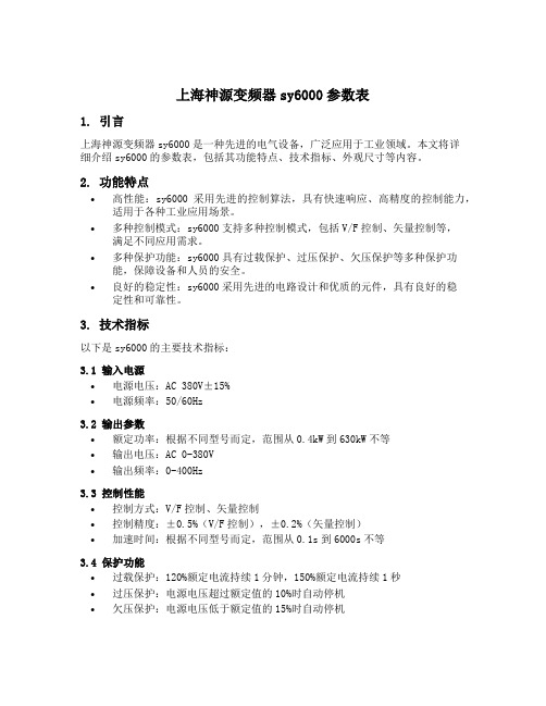
上海神源变频器sy6000参数表1. 引言上海神源变频器sy6000是一种先进的电气设备,广泛应用于工业领域。
本文将详细介绍sy6000的参数表,包括其功能特点、技术指标、外观尺寸等内容。
2. 功能特点•高性能:sy6000采用先进的控制算法,具有快速响应、高精度的控制能力,适用于各种工业应用场景。
•多种控制模式:sy6000支持多种控制模式,包括V/F控制、矢量控制等,满足不同应用需求。
•多种保护功能:sy6000具有过载保护、过压保护、欠压保护等多种保护功能,保障设备和人员的安全。
•良好的稳定性:sy6000采用先进的电路设计和优质的元件,具有良好的稳定性和可靠性。
3. 技术指标以下是sy6000的主要技术指标:3.1 输入电源•电源电压:AC 380V±15%•电源频率:50/60Hz3.2 输出参数•额定功率:根据不同型号而定,范围从0.4kW到630kW不等•输出电压:AC 0-380V•输出频率:0-400Hz3.3 控制性能•控制方式:V/F控制、矢量控制•控制精度:±0.5%(V/F控制),±0.2%(矢量控制)•加速时间:根据不同型号而定,范围从0.1s到6000s不等3.4 保护功能•过载保护:120%额定电流持续1分钟,150%额定电流持续1秒•过压保护:电源电压超过额定值的10%时自动停机•欠压保护:电源电压低于额定值的15%时自动停机3.5 外观尺寸•尺寸:根据不同型号而定,具体尺寸详见产品手册4. 应用领域sy6000广泛应用于以下领域: - 机械制造业:用于驱动各种机械设备,如输送带、机床等。
- 化工行业:用于控制化工设备的转速和运行状态。
- 矿山行业:用于控制矿山设备的运行,提高矿石开采效率。
- 建筑行业:用于控制建筑设备,如风机、水泵等。
5. 总结上海神源变频器sy6000是一款功能强大、性能稳定的变频器。
本文对其参数表进行了详细介绍,包括功能特点、技术指标、外观尺寸等内容。
06cr18ni11ti成分

06Cr18Ni11Ti是一种常见的不锈钢材料,其成分主要包括以下几个方面:1. 化学成分06Cr18Ni11Ti的化学成分主要由以下几个元素组成:碳(C)、硅(Si)、锰(Mn)、磷(P)、硫(S)、铬(Cr)、镍(Ni)和钛(Ti)。
其中,碳、硅、锰、磷和硫这几个元素被认为是杂质元素,它们的含量在不锈钢材料中需要控制在一定范围内,以保证材料的质量和性能。
而铬、镍和钛则是不锈钢材料中的主要合金元素,它们的含量和比例决定了不锈钢的耐腐蚀性能、强度和塑性。
2. 各元素含量根据06Cr18Ni11Ti不锈钢的标准,其各元素的含量应符合下表:元素 C Si Mn P S Cr Ni Ti含量()≤0.08 ≤1.00 ≤2.00 ≤0.045 ≤0.03 17.00-19.00 9.00-13.00 5*C其中,C表示碳的含量,Si表示硅的含量,Mn表示锰的含量,P表示磷的含量,S表示硫的含量,Cr表示铬的含量,Ni表示镍的含量,Ti 表示钛的含量。
这些元素的含量在不锈钢的生产和使用过程中起着至关重要的作用,它们的含量决定了不锈钢的物理和化学性质,直接影响了不锈钢的使用性能和寿命。
3. 材料特性根据06Cr18Ni11Ti不锈钢的成分,可以得出以下几点关于其材料特性的描述:(1)耐腐蚀性能:由于含有17以上的铬和9以上的镍,06Cr18Ni11Ti不锈钢具有良好的耐腐蚀性能,能够在大多数酸性和碱性介质中保持稳定的化学性能,因此被广泛应用于化工、医药、食品等领域。
(2)热处理性能:由于含有适量的钛元素,06Cr18Ni11Ti不锈钢具有良好的热处理性能,能够通过固溶退火、奥氏体化等热处理工艺改善材料的性能,提高其强度和塑性。
(3)焊接性能:06Cr18Ni11Ti不锈钢具有良好的焊接性能,可通过常规的焊接工艺进行加工和连接,焊接接头的性能与母材接近,因此被广泛用于需要焊接的场合。
通过以上对06Cr18Ni11Ti不锈钢成分的介绍,我们可以看出,该材料的化学成分对其性能和用途起着决定性的作用。
TY6000说明书
5.2 启停控制(P1 组)...............................................43 5.3 辅助运行(P2 组)...............................................46 5.4 IO端子控制(P3 组)...........................................48 5.5 模拟及脉冲功能(P4 组) ...................................55 5.6 PLC运行(P5 组) ...............................................57 5.7 纺织摆频(P6 组)...............................................59 5.8 PID控制(P7 组) ................................................59 5.9 定长功能(P8 组)...............................................62 5.10 高级控制(P9 组).............................................62 5.11 电机参数(PA组).............................................63 5.12 MODBUS通讯(Pb组).....................................64 5.13 显示控制(PC组) .............................................65 5.14 保护及故障参数(Pd组) ..................................67 5.15 运行历史记录(PE组) .....................................69 5.16 参数保护(PF组)..............................................69
新泰立NOVALINK调光台使用说明书

THEATRELIGHT调光台系列NOVALINK电脑调光台使用说明书THEATRELIGHT-ASIA中山新泰立灯光有限公司目录1、概述 (3)2、NOVALINK电脑调光台的规格 (3)3、装箱清单 (3)4、使用条件 (3)5、使用注意事项 (4)6、后面板介绍 (4)6.1、电源输入的连接 (4)6.2、麦克风口和音控接口 (4)6.3、遥控接口 (5)6.4、DMX512信号线缆的插口 (5)6.5、网络接口 (6)7、正面板介绍 (6)8、操作说明 (9)8.1、待用状态调整 (9)8.2、手动操作方式 (10)8.3、记录操作方式 (10)8.4、其它操作 (17)8.5、软配接操作 (20)说明:本操作说明书的重点是第5、8章,其中8.3,8.4.7和8.5是操作的核心。
NOVALINK电脑调光台使用说明书1.概述NOVALINK电脑调光台是新西兰Theatrelight公司设计的具有音控走灯功能和软配接等功能的调光台。
通过软配接,NOVALINK24可控制512硅路,NOVALINK36可控制1024硅路。
LCD显示软配接、测试亮度或各硅路和光路的实际输出亮度等。
NOVALINK调光台功能强大、性能稳定、抗震性好,是商店、旅馆、学校、宴会厅、小型演播室和小型流动演出理想的调光设备。
1)、DMX-512(USITT1990)标准信号输出。
2)、在集控上可存储手控、渐变、走灯和演出场景。
通过键盘进行软配接。
3)、LCD显示软配接、测试亮度或各硅路和光路的实际输出亮度等。
4)、淡入、淡出时间可分别在瞬间到30分钟之间任意设定。
5)、独特的音控走灯功能。
6)、手动交叉换场功能方便现场演出。
7)、特殊定制的长寿命电脑按键和带防尘膜的推杆。
8)、通过遥控可控制演出场景的进行。
9)、内存掉电保护,可保持存储内容5年。
10)、可使用SD卡备份存储内容,在意外的情况下恢复存储内容。
2. NOVALINK电脑调光台的规格型号输出光路输出硅路外型尺寸(mm)重量(kg)NOVALINK24 24 512 100H×540W×340D 7.5NOVALINK36 36 1024 100H×775W×340D 9.53. 装箱清单1)、NOVALINK电脑调光台一台;2)、2米DMX信号线一条(选配);3)、电源线一条;4)、使用说明书一份;5)、保修卡和合格证各一张;6)、防尘罩一张(选配)。
Voltech PM6000电源分析仪说明书

V oltech PM6000Power AnalyzerA New Standard in Power AnalysisThe Voltech PM6000 Power Analyzer• Up to 6 wattmeter channels• 0.02% basic accuracy for definitive power loss and efficiency measurements • Sampling at 40MHz (5MHz minimum) for error-free results• Outstanding rejection of common-mode signals for accuracy in all applications • A bright color display and intuitive menu system for ease of use • Connectivity: RS232, Printer, Ethernet, USB* (*Future Release)New generation power analyzer PM6000 has the power to provide:Versatile, accurate, fully-featuredand yet easy-to-useThe PM6000 provides definitive measurements of all electrical power quantities on all products that consume, convert or generate electrical power. The Voltech PM6000 combines years of power measurement know-how with the latest digital signal processing technology to provide a unique combination of measurement and reporting features that will solve power measurement problems.Why the PM6000? There is a constant consumer and legislative pressure to design electrical products that are more efficient, power electronics designers use more and more sophisticated control methods and increases in switching frequency to achieve this. Therefore more sophisticated, more accurate and higher bandwidth power measurements are required to validate and test power electronic designs.The PM6000 has been designed especially to meet the needs of today’s design and test engineers by providing greater flexibility and bandwidth at high accuracy.The PM6000 is an advanced digital sampling power analyzer. From 1 to 6 measurement channels may be fitted to a PM6000. Each measuring channel is a separate wattmeter with fully floating inputs for connection to the voltage and current of the power circuit to be measured.Voltages up to 2000 Vpk may be connected directly to the measurements channels and a wide variety of current transducers may be used, including wide-bandwidth resistive current shunts from Voltech. The Voltech shunts plug directly into the measurement channel for convenience, and have the advantage that the shunt’s calibration data is automatically transferred to the PM6000, providing optimum accuracy for the complete measurement path. For other external current transducers, each channel can supply ±12V DC power. Unique and proprietary algorithms are then used to process the samples and provide stable and accurate measurements in all applications.MeasurementsFront PanelThe intuitive menu system will guide you through the set-up and control of the analyzer. Working through the options step-by-step allows you to configure channels into groups for a variety of multi-phase connections, to set scaling for external voltage and current transducers, and to choose the required measurements.Rear PanelAt the rear, comprehensive control is provided via RS232. Standard printers may be connected directly for local print-out of numeric results.The ethernet port allows for powerful control and datalogging to a network drive.Set-Up and Controlcontrolfunction keysAdvantages• U p to six channels configurable as required, for example AC input plus 5 DC outputs or three-phase input and output.• Excellent 0.02% basic accuracy - useful for high efficiency measurements.• Accurate on all waveforms.• Samples continuously, without gaps at 5 MSPS so there is no missing dataduring integration or low-power standby measurements.Power transformers are characterized under open-circuit and short-circuit conditions. Open-circuit, the power factor of the transformer is closeto zero (<0.01), which demands very low phase error, from the power analyzer.The analog design of the PM6000 ensures that its voltage and current channels are carefully matched, providing optimum performance at low power factors.Applications - Power TransformersAdvantages• Up to six channels for simultaneous three-phase input and output – Star (Wye) or Delta connection.• Accurate at low power factors. (<0.01)• Simultaneous measurement of rms and mean voltage as required by IEC76 and IEEEC57.• Measure turns ratio directly using the math function.MeasurementsWatts, Vrms, Vrmn, Arms, VA, VAr, Apk, Harmonics, THD, Inrush.K-factor and corrected power to IEEE and IEC standards.Applications – Variable Frequency Drivesand MachinesThe versatile PM6000 will make simultaneous measurements at the input and output of a drive, allowing accurate efficiency measurements under all load and speed conditions.Advantages• Up to six channels configurable as required, for example 3 wattmeter, three- phase input, DC bus and two-wattmeter drive output and torque and speed measured simultaneously.• Excellent 0.02% basic accuracy - useful for high efficiency measurements.• 10MHz bandwidth captures all motor frequency and high-frequency data for the most accurate overall power measurement.• High rejection of common-mode signals found on the drive output. 140dB @ 60Hz, 95dB@1MhzMeasurementsApplications - Power Integration / StandbyThe power consumption of everyday home and office electrical appliances is of importance to consumers and generators of electricity alike.When the power consumption varies over time, then integration of the power ( W-h integration) is required. The PM6000 provides comprehensive integration features suitable for Energy Star measurements and for low-power measurements in accordance with international directives, eg. IEC 62301 which also requires crest factor measurements up to 8 and 50 harmonics.Advantages• Excellent 0.02% basic accuracy - useful for high efficiency measurements.• Accurate on all waveforms.• Samples continuously, without gaps at 5 MSPS so there is no missingdata during integration or low-power standby measurements.• Versatile current channel input for low – current measurements. 1A Voltech plug-in shunt available.MeasurementsIEC 62301Voltech continues to be a leader in producing power analyzers that meet the ever changing needs of today’s world. A mandatory measurement for products in Europe and many other countries, the IEC standards definespecific methods for testing current harmonics and flickerApplications - IEC Harmonics and FlickerAdvantages.• F ull compliance testing for EMC laboratories when used with an AC Source and Impedance Network.• S uperb pre-compliance measurements when used stand-alone.• P C software plays back previous tests and generates reports suitable for technical construction files.• D iscrete Fourier Transform (DFT) ‘reference instrument’ implementation avoids the problems of Fast Fourier Transform (FFT) analyzers.• S olutions for harmonics and flicker to 75A.(voltage changes). The PM6000 and its easy-to-use software provide design engineers and EMC test laboratories with a comprehensive suite of measurements and reports that fully comply with the latest standards.To measure the efficiency of a high-frequency ballast, its essential tohave an accurate measurement of both the input and output power of the ballast. With unbeatable accuracy at both low and high frequencies, and superior common-mode rejection, the PM6000 will make the most accurate efficiency measurements possible.Applications - Lighting BallastsPurposely designed for lighting applications, this device overcomes problems that are usually found when using conventional or Hall effect CTs.• Convenient: No need to feed cables through a CT core. • Better than 1% accuracy: Trifilar wound toroidal core.• 5kHz to 1MHz bandwidth . • 5mA to 1A measurement rangeAccessoriesPM6000 Back Panel with 6 channels and 3 Voltech 30A shunts fitted.• Accuracy better than 1%• Connect to the PM6000 via safety leads and 1A shunt • CL100 100A:1A • CL1000 1000A:1A• Accuracy (23°C ± 5°C): ± 0.2% of specified ratio • Frequency range: 45Hz to 1kHz• Current range: 100:1 ratio: 10A to 120A rms 1000:1 ratio: 100A to 1200A rms• Maximum input current: 1000A continuous 2000A for 1 hour • Phase error (23°C ± 5°C): Better than ± 0.1° at 50HzSolid-state switch for energizing loads (up to 200Apk) at either the peak or the zero crossing of AC voltage. Ideal for inrush current testing.Clamp-on Current TransformersCT1000 –Dual Ratio Precision Current TransformerPS1000 - Inrush SwitchBallast CTPM6000 ChassisWith color VGA display and 3½” floppy drive. Connectivity: RS232, Printer, Ethernet, USB*(*Future Release)Hard Disk Drive (Optional)PM6000 Measurement ChannelHigh performance wattmeter channel. Voltage 1500V , Current 2.5V for shunt or current transducer. ±12V DC supply for external current transducer.OrderingVoltageCurrentPower1. At 23ºC ± 5ºC, valid 1 year from calibration.2. %rdg = percentage of reading, % rng = percentage of range, F = frequency in kHz.3. Vrng = Voltage range: 5, 10, 20, 50, 100, 200, 500, 1000, 2000Vpk.4. Irng = Current range.30A shunt: 0.5, 1, 2.5, 5, 10, 20, 50, 100, 250Apk.1A shunt: 0.01, 0.02, 0.05, 0.1, 0.2, 0.5, 1.0, 2.0, 5.0Apk.Voltage input: 0.005, 0.010, 0.025, 0.05, 0.10, 0.25, 0.50, 1.0, 2.5Vpk.1A Shunt1A rms, 5Apk precision measuring shunt withcalibration stored in EEPROM. (Bandwidth 10MHz)30A shunt30A rms, 200Apk precision measuring shunt with calibration stored in EEPROM. (Bandwidth 1MHz)Lead set2 pairs (yellow and black) 1.5m, 2000V , 30A leads with safety connectors and alligator clips.Magnitude(V)=0.02%rdg +0.05%rng +(0.001%x F )rdg +20mVPhase (º)=0.005+ 0.0003x + +(0.001xF)][V rng V 0.05VMagnitude(A)=0.02%rdg +0.05%rng +(0.001%x F )rdg +20uVZ EXTPhase (º)=0.0025+ 0.0005x + +(0.0006x F)][I rng I0.00004IxZ EXT Specifications5. Ø = angle between voltage and current.6. Zext = 0.01 (30A shunt), 0.5 (1A shunt), 0.0125 (default voltage input) ohms.Voltech Instruments Inc.11637 Kelly Road, Suite 306Fort Myers, FL 33908USATel: (239) 437 0494Fax: (239) 437 3841**********************Voltech has an intensive program of design and development andreserves the right to alter product specification without notice. Although every care has been taken in compiling this information Voltech does not accept any liability for errors or omissions. ©2006 Voltech.Voltech Instruments Ltd.148 Harwell Int’l Business Centre Didcot, Oxon. OX11 0RA UKTel: +44 (0) 1235 834555Fax: +44 (0) 1235 835016Email:****************.ukV oltechDistributorVPN: 86-506/9Error(Watts)= + + (tan 0x(Vh1Ph error+Ah1Ph error ) x ) x W [V RMS V RMS error A RMSA RMS error]180 π。
Ni基合金NO6600的焊接工艺性介绍

Ni基合金NO6600的焊接工艺性介绍发表时间:2019-10-18T14:09:37.547Z 来源:《基层建设》2019年第18期作者:冯益锋[导读] 摘要:本文根据镍基合金NO6600材料的特点,针对有害气体对镍基材料焊接时的影响、焊缝金属流动性差、焊接熔深浅等分析该材料的焊接性能,论述镍基合金N06600管道的焊接工艺,对相应材料的焊接工艺的制定提供了重要指导作用。
中石化第五建设有限公司中国广州摘要:本文根据镍基合金NO6600材料的特点,针对有害气体对镍基材料焊接时的影响、焊缝金属流动性差、焊接熔深浅等分析该材料的焊接性能,论述镍基合金N06600管道的焊接工艺,对相应材料的焊接工艺的制定提供了重要指导作用。
关键词:镍基合金N06600;焊接性能分析;焊接工艺;指导Abstract:In this article,based on the nickel-base alloy NO6600 characteristics of the material for the harmful, gas welding nickel-based material impacts weld metal poor mobility, such as weld depth analysis of the material weldability, discusses N06600 nickel alloy pipe welding process, for corresponding material welding process was provide important guidance.Keyword:Nickel-based alloy N06600; welding performance analysis; welding process; important guidance0、前言镍基合金具有良好的高温强度和优良的耐磨损、耐高温、抗热震冲击、抗氧化性能和优良的耐强酸、氧化-还原复合介质、卤族以及化合物、强还原介质、氢氟酸、碱性介质、含有氯离子的氧化还原介质的腐蚀。
Altivar Process ATV600产品数据手册说明书
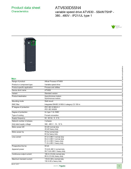
i s c l a i m e r : T h i s d o c u m e n t a t i o n i s n o t i n t e n d e d a s a s u b s t i t u t e f o r a n d i s n o t t o b e u s e d f o r d e t e r m i n i n g s u i t a b i l i t y o r r e l i a b i l i t y o f t h e s e p r o d u c t s f o r s p e c i f i c u s e r a p p l i c a t i o n sProduct data sheetCharacteristicsATV630D55N4variable speed drive ATV630 - 55kW/75HP -380...480V - IP21/UL type 1MainRange of productAltivar Process ATV600Product or component type Variable speed drive Product specific application Process and utilities Device short name ATV630VariantStandard version Product destination Asynchronous motors Synchronous motors Mounting mode Wall mountEMC filterIntegrated EN/IEC 61800-3 category C3 150 m IP degree of protection IP21 IEC 61800-5-1IP21 IEC 60529Degree of protection UL type 1 UL 508C Type of cooling Forced convection Supply frequency50...60 Hz - 5...5 %Network number of phases 3 phases[Us] rated supply voltage 380...480 V - 15...10 %Motor power kW 55 kW normal duty 45 kW heavy duty Motor power hp 75 hp normal duty 60 hp heavy duty Line current97.2 A 380 V normal duty 84.2 A 480 V normal duty 81.4 A 380 V heavy duty 71.8 A 480 V heavy duty Prospective line Isc 50 kAApparent power70 kVA 480 V normal duty 59.7 kVA 480 V heavy duty Continuous output current 106 A 2.5 kHz normal duty 88 A 2.5 kHz heavy duty Maximum transient current116.6 A 60 s normal duty 132 A 60 s heavy dutyAsynchronous motor control profile Constant torque standardVariable torque standardOptimized torque modeSynchronous motor control profile Permanent magnet motorOutput frequency0.0001...0.5 kHzSpeed drive output frequency0.1...599 HzNominal switching frequency 2.5 kHzSwitching frequency 2...8 kHz adjustable2.5...8 kHz with derating factorSafety function STO (safe torque off) SIL 3Discrete input logic16 preset speedsCommunication port protocol Modbus TCPModbus serialEthernetOption card Communication module Profibus DP V1 slot ACommunication module Profinet slot ACommunication module DeviceNet slot ACommunication module Modbus TCP/EtherNet/IP slot ACommunication module CANopen daisy chain RJ45 slot ACommunication module CANopen SUB-D 9 slot ACommunication module CANopen screw terminals slot ADigital and analog I/O extension module slot A/slot BOutput relay extension module slot A/slot BCommunication module Ethernet IP/Modbus TCP/MD-Link slot A ComplementaryOutput voltage<= power supply voltagePermissible temporary current boost 1.1 x In 60 s normal duty1.5 x In 60 s heavy dutyMotor slip compensation Automatic whatever the loadCan be suppressedNot available in permanent magnet motor lawAdjustableAcceleration and deceleration ramps Linear adjustable separately from 0.01...9999 sBraking to standstill By DC injectionProtection type Safe torque off motorMotor phase break motorSafe torque off driveOverheating driveShort-circuit protection driveMotor phase break driveOverspeed driveBreak on the control circuit driveOvervoltages on the DC bus driveOverload of output voltage driveLine supply overvoltage driveLine supply phase loss driveLine supply undervoltage driveOvercurrent between output phases and earth driveThermal protection motorThermal protection driveFrequency resolution Display unitAnalog inputElectrical connection Removable screw terminals 0.5...1.5 mm² AWG 20...AWG 16 controlScrew terminal 70...120 mm² AWG 1/0...250 kcmil line sideScrew terminal 70...120 mm² AWG 1/0...250 kcmil motor Connector type RJ45 Ethernet/Modbus TCP on the remote graphic terminalRJ45 Modbus serial on the remote graphic terminalPhysical interface2-wire RS 485 Modbus serialTransmission frame RTU Modbus serialTransmission rate10/100 Mbit/s Ethernet IP/Modbus TCP4.8, 9.6, 19.2, 38.4 kbit/s Modbus serialExchange mode Half duplex, full duplex, autonegotiation Ethernet/Modbus TCP Data format8 bits, configurable odd, even or no parity Modbus serialType of polarization No impedance Modbus serialNumber of addresses 1...247 Modbus serialMethod of access Slave Modbus TCPSupply Internal supply for reference potentiometer (1 to 10 kOhm) 10.5 V DC +/- 5 % <= 10 mA overload andshort-circuit protectionExternal supply for digital inputs 24 V DC 19...30 V <= 1.25 mA overload and short-circuit protectionInternal supply for digital inputs and STO 24 V DC 21...27 V <= 200 mA overload and short-circuitprotectionLocal signalling 3 LEDs local diagnostic3 LEDs dual colour embedded communication status4 LEDs dual colour communication module status1 LED red presence of voltageWidth290 mmHeight922 mmDepth323 mmProduct weight56.5 kgAnalogue input number3Analogue input type Software-configurable voltage AI1, AI2, AI3 0...10 V DC 30 kOhm 12 bitsSoftware-configurable current AI1, AI2, AI3 0...20 mA/4...20 mA 250 Ohm 12 bitsDiscrete input number8Discrete input type Programmable DI1...DI6 24 V DC 3.5 kOhmProgrammable as pulse input DI5, DI6 0...30 kHz 24 V DCSafe torque off STOA, STOB 24 V DC > 2.2 kOhmInput compatibility Level 1 PLC EN/IEC 61131-2 DI1...DI6 discrete inputLevel 1 PLC IEC 65A-68 DI5, DI6 discrete inputLevel 1 PLC EN/IEC 61131-2 STOA, STOB discrete inputDiscrete input logic Positive logic (source) DI1...DI6 < 5 V > 11 VNegative logic (sink) DI1...DI6 > 16 V < 10 VPositive logic (source) DI5, DI6 < 0.6 V > 2.5 VPositive logic (source) STOA, STOB < 5 V > 11 VAnalogue output number2Analogue output type Software-configurable voltage AO1, AO2 0...10 V DC 470 Ohm 10 bitsSoftware-configurable current AO1, AO2 0...20 mA 10 bitsSampling duration 2 ms +/- 0.5 ms DI1...DI4 discrete input5 ms +/- 1 ms DI5, DI6 discrete input5 ms +/- 0.1 ms AI1, AI2, AI3 analog input10 ms +/- 1 ms AO1 analog outputAccuracy+/- 0.6 % AI1, AI2, AI3 for a temperature variation 60 °C analog input+/- 1 % AO1, AO2 for a temperature variation 60 °C analog outputLinearity error+/- 0.15 % of maximum value analog input AI1, AI2, AI3+/- 0.2 % analog output AO1, AO2Relay output number3Relay output type Configurable relay logic R1 fault relay NO/NC 100000 cyclesConfigurable relay logic R2 sequence relay NO 100000 cyclesConfigurable relay logic R3 sequence relay NO 100000 cyclesRefresh time 5 ms +/- 0.5 ms R1, R2, R3 relay outputMinimum switching current 5 mA 24 V DC R1, R2, R3 relay outputMaximum switching current 3 A 250 V AC resistive 1 R1, R2, R3 relay output3 A 30 V DC resistive 1 R1, R2, R3 relay output2 A 250 V AC inductive 0.4 7 ms R1, R2, R3 relay output2 A 30 V DC inductive 0.4 7 ms R1, R2, R3 relay outputIsolation Between power and control terminalsFunctionality FullSpecific application UtilityIP degree of protection IP21Discrete and process manufacturing Building - HVAC compressor centrifugalFood and beverage processing other applicationMining mineral and metal fanMining mineral and metal pumpOil and gas fanWater and waste water other applicationBuilding - HVAC screw compressorFood and beverage processing pumpFood and beverage processing fanFood and beverage processing atomizationOil and gas electro submersible pump (ESP)Oil and gas water injection pumpOil and gas jet fuel pumpOil and gas compressor for refineryWater and waste water centrifuge pumpWater and waste water positive displacement pumpWater and waste water electro submersible pump (ESP)Water and waste water screw pumpWater and waste water lobe compressorWater and waste water screw compressorWater and waste water compressor centrifugalWater and waste water fanWater and waste water conveyorWater and waste water mixerPower range55...100 kW 380...440 V 3 phases55...100 kW 480...500 V 3 phasesMotor starter type Variable speed driveEnvironmentInsulation resistance> 1 mOhm 500 V DC for 1 minute to earthNoise level62.4 dB 86/188/EECPower dissipation in W131 W natural convection 380 V 2.5 kHz917 W forced convection 380 V 2.5 kHzVolume of cooling air295 m3/hOperating position Vertical +/- 10 degreeTHDI<= 48 % from 80...100 % of load IEC 61000-3-12Electromagnetic compatibility Conducted radio-frequency immunity test level 3 IEC 61000-4-61.2/50 µs - 8/20 µs surge immunity test level 3 IEC 61000-4-5Electrical fast transient/burst immunity test level 4 IEC 61000-4-4Electrostatic discharge immunity test level 3 IEC 61000-4-2Radiated radio-frequency electromagnetic field immunity test level 3 IEC 61000-4-3 Pollution degree 2 EN/IEC 61800-5-1Vibration resistance 1.5 mm peak to peak 2...13 Hz IEC 60068-2-61 gn 13...200 Hz IEC 60068-2-6Shock resistance15 gn 11 ms IEC 60068-2-27Relative humidity 5...95 % without condensation IEC 60068-2-3Ambient air temperature for operation-15...50 °C without derating50...60 °C with derating factorAmbient air temperature for storage-40...70 °COperating altitude1000...4800 m with current derating 1 % per 100 m<= 1000 m without deratingEnvironmental characteristic Chemical pollution resistance class 3C3 EN/IEC 60721-3-3Dust pollution resistance class 3S3 EN/IEC 60721-3-3Standards EN/IEC 61800-3EN/IEC 61800-3 environment 1 category C2EN/IEC 61800-3 environment 2 category C3UL 508CEN/IEC 61800-5-1IEC 61000-3-12IEC 60721-3IEC 61508IEC 13849-1Product certifications DNV-GLTÜVREACHATEX zone 2/22ULCSAATEX INERISMarking CEOffer SustainabilitySustainable offer status Green Premium productRoHS (date code: YYWW)Compliant - since 1426 - Schneider Electric declaration of conformity Schneider Electric declaration of conformity REAChReference not containing SVHC above the threshold Reference not containing SVHC above the threshold Product environmental profile AvailableProduct environmental Product end of life instructionsAvailableEnd of life manualProduct data sheetATV630D55N4 Dimensions DrawingsDimensionsViews: Front - LeftDrives Without IP21 Top Cover Views: Left - RearClearancesMounting TypesMounting Type A: Individual IP21a ≥ =110 mm (4.33 in.)Mounting Type B: Side by Side IP20 (Possible, 2 Drives Only)Mounting Type C: Individual IP20a ≥ =110 mm (4.33 in.)Connections and SchemaSingle or Three-Phase Power Supply with Upstream Breaking via Line ContactorConnection diagrams conforming to standards EN 954-1 category 1 and IEC/EN 61508 capacity SIL1, stopping category 0 in accordance with standard IEC/EN 6(1)Use digital output R1 set to operating state Fault to switch Off the product once an error is detected.A1 :DriveKM1 :Line Contactor Q2, Q3 :Circuit breakers S1, S2 :PushbuttonsT1 :Transformer for control partSingle or Three-Phase Power Supply with Downstream Breaking via Switch DisconnectorConnection diagrams conforming to standards EN 954-1 category 1 and IEC/EN 61508 capacity SIL1, stopping category 0 in accordance with standard IEC/EN(1)Use digital output R1 set to operating state Fault to switch Off the product once an error is detected.A1 :DriveQ1 :Switch disconnectorControl Block Wiring Diagram(1)Safe Torque Off(2)Analog Output(3)Digital Input(4)Reference potentiometer(5)Analog InputA1 :ATV6.. DriveR1A, R1B, R1C :Fault relayR2A, R2C :Sequence relayR3A, R3C :Sequence relaySensor ConnectionIt is possible to connect either 1 or 3 sensors on terminals AI2 or AI3.Sink / Source Switch ConfigurationThe switch is used to adapt the operation of the logic inputs to the technology of the programmable controller outputs.●Set the switch to Source (factory setting) if using PLC outputs with PNP transistors.●Set the switch to Ext if using PLC outputs with NPN transistors.Switch Set to SRC (Source) Position Using the Output Power Supply for the Digital InputsSwitch Set to SRC (Source) Position and Use of an External Power Supply for the DIsSwitch Set to SK (Sink) Position Using the Output Power Supply for the Digital InputsSwitch Set to EXT Position Using an External Power Supply for the DIsPerformance CurvesDerating Curves40 °C (104 °F) - Mounting type A, B and C50 °C (122 °F) - Mounting type A, B and C60 °C (140 °F) - Mounting type B and C In :Nominal Drive CurrentSF :Switching FrequencyMotor Starter BOMOur Proposal: Circuit Breaker + Contactor + Drive for Motor Power 55 kW and 380 or 440 VACNon contractual pictures.(*) You can select the contactor proposed or variants. Please consider examples hereafter or follow the link to the complete offer.(**) You can select the breaker proposed or variants. Please consider examples hereafter or follow the link to the complete offer.。
Victron Energy Multi RS 48 6000 双轨式 PV 输入混合逆变器说明书
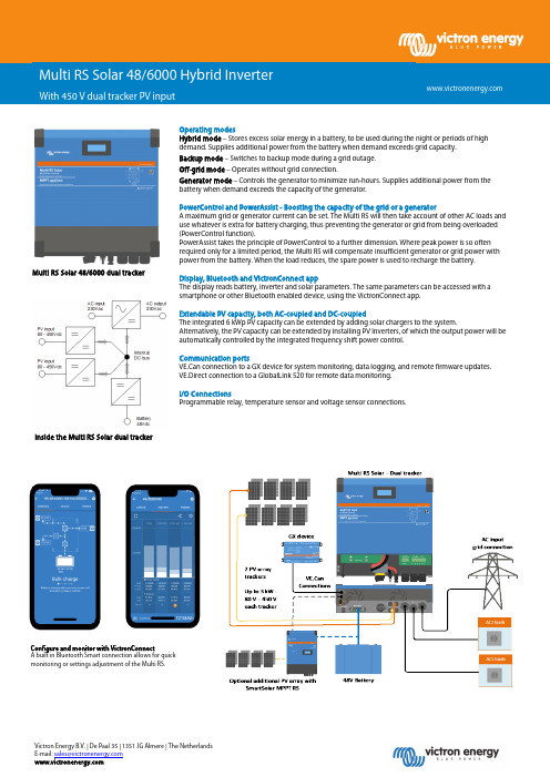
Victron Energy B.V. | De Paal 35 | 1351 JG Almere | The Netherlands E-mail: *********************** Operating modesHybrid mode – Stores excess solar energy in a battery, to be used during the night or periods of high demand. Supplies additional power from the battery when demand exceeds grid capacity. Backup mode – Switches to backup mode during a grid outage. Off-grid mode – Operates without grid connection.Generator mode – Controls the generator to minimize run-hours. Supplies additional power from the battery when demand exceeds the capacity of the generator.PowerControl and PowerAssist - Boosting the capacity of the grid or a generatorA maximum grid or generator current can be set. The Multi RS will then take account of other AC loads and use whatever is extra for battery charging, thus preventing the generator or grid from being overloaded (PowerControl function).PowerAssist takes the principle of PowerControl to a further dimension. Where peak power is so often required only for a limited period, the Multi RS will compensate insufficient generator or grid power with power from the battery. When the load reduces, the spare power is used to recharge the battery.Display, Bluetooth and VictronConnect appThe display reads battery, inverter and solar parameters. The same parameters can be accessed with a smartphone or other Bluetooth enabled device, using the VictronConnect app.Extendable PV capacity, both AC-coupled and DC-coupledThe integrated 6 kWp PV capacity can be extended by adding solar chargers to the system.Alternatively, the PV capacity can be extended by installing PV Inverters, of which the output power will be automatically controlled by the integrated frequency shift power control.Communication portsVE.Can connection to a GX device for system monitoring, data logging, and remote firmware updates. VE.Direct connection to a GlobalLink 520 for remote data monitoring.I/O ConnectionsProgrammable relay, temperature sensor and voltage sensor connections.Multi RS Solar 48/6000 dual trackerInside the Multi RS Solar dual trackerConfigure and monitor with VictronConnectA built in Bluetooth Smart connection allows for quick monitoring or settings adjustment of the Multi RS.PowerControl & PowerAssist Yes Transfer switch 50 A Maximum AC input and pass-through current 50 A DC Input voltage range (1)38 – 62 VAC Output (2)Output voltage: 230 VAC ± 2 %Frequency: 50 Hz ± 0,1 % Maximum continuous inverter current: 25 AacContinuous output power at 25 °C Increases linearly from 4800 W at 46 VDC to 5300 W at 52 VDCContinuous output power at 40 °C 4500 W Continuous output power at 65 °C 3000 WPeak power (3)9 kW for 3 seconds7 kW for 4 minutes Short-circuit output current 45 AMax. AC output overcurrent protection 30 AEfficiency 96,5 % at 1 kW load94 % at 5 kW load Zero load power consumption 20 WLow Battery shutdown 37.2 V (adjustable) Low battery restart 43.6 V (adjustable) Maximum open circuit PV array voltage (4)450 VStart-up voltage 120 VMPPT operating voltage range 80 – 450 V Maximum operational PV input current limit 13 A Maximum PV conversion power 6 kW total – 3 kW per tracker Maximum PV short circuit current 16 AEarth leakage trip level 30 mA Isolation fail level (detection before start-up) 100 kΩAC Input Nominal Voltage: 230 VAC, Input voltage range: 187-265 VAC Nominal frequency: 50 Hz, Input frequency: 45-65 HzAC inrush current: NAProgrammable charge voltage range (5)36 – 60 VCharge voltage 'absorption' Default setting: 57,6 V (adjustable)Charge voltage 'float' Default setting: 55,2 V (adjustable)Maximum charge current from AC (6)88 A @ 57,6 VDCTotal maximum charge current (AC + PV) 100 A DCBattery temperature sensor IncludedBattery voltage sense YesAuxiliary output (AC-out-2) (7)Yes3-phase and parallel operation 3-phase support with one unit per phase. Parallel not supported. Programmable relay (8)YesProtections (9) a - gData communications ports (10)VE.Direct, VE.Can & BluetoothBluetooth frequency & power 2402 - 2480 Mhz, 4 dBmProgrammable analog/digital input/output ports Yes, 2xRemote on-off YesOperating temperature range -40 to +65 °C (fan assisted cooling)Maximum altitude 2000 mHumidity (non-condensing) max 95 %Material & Colour steel, blue RAL 5012Protection category IP21 Protective Class: IBattery-connection M8 boltsPV Connection 2 strings, each with positive and negative MC4230 VAC-connection Screw terminals 10 mm² (6 AWG)Weight 12,3 kgDimensions (hxwxd) 425 x 460 x 125 mmSafety EN-IEC 60335-1, EN-IEC 60335-2-29, EN-IEC 62109-1, EN-IEC 62109-2Emission, Immunity EN 55014-1, EN 55014-2, EN-IEC 61000-3-2, EN-IEC 61000-3-3, IEC 61000-6-1, IEC 61000-6-2,IEC 61000-6-3, Pollution Degree 2Overvoltage Category Battery: OVC 1, PV port: OVC II, AC in / AC out: OVC III1) Minimum start-up voltage is 41 VDC. Over-voltage disconnect: 65,5 V.2) Can be adjusted to 240 VAC and 60 Hz3) Peak power capacity and duration depends on start temperature of heatsink.Mentioned times are with cold unit.4) The maximum PV voltage should not exceed 8x battery float voltage.If for example the float voltage of the battery is 50 V,the maximum PV voltage should not exceed 8 x 50 = 400 V.5) The Charger set points (float & absorption) can be set to max 60 V.The output voltage at the charger terminals can be higher due to compensationfor temperature & voltage drop over the battery cables.The maximum output current is reduced on a linear basis from full current at 60 V to5 A at 62 V. The equalization voltage can be set to max 62 V, the equalization currentpercentage can be set to max 6 %.6) The maximum charge current from AC sources depends on input voltage and battery current. At 230V input and 57.6V battery voltage, and 25C ambient, the maximum charge current is 88 A. See manual, limitations section, for further details.7) AC-out-2 is connected directly to the AC input and intended for non-critical loads. The AC-out-2 load is taken into account by PowerControl & PowerAssist.8) Programmable relay which can be set for general alarm, DC under voltage or genset start/stop function. DC rating: 4 A up to 35 VDC and 1 A up to 70 VDC9) Protection key: a) output short circuit b) overload c) battery voltage too high d) battery voltage too low e) temperature too high f) 230 VAC on inverter output g) solar earth leakage.10) Not currently compatible with VE.Smart Networks. Connection to a GX device (i.e. Cerbo GX) must be made via the VE.Can interface. The VE.Direct interface is for connection to the GlobalLink 520.。
腾龙TEK6000变频器使用说明书
TM目录第一章: 前言1.1 购入时注意事项 (1)1.2 产品型号及铭牌说明 (2)1.3 产品一览表 (3)1.4 标准规格 (4)第二章: 安装与配线2.1 安装 (5)2.1.1 安装方向与空间 (5)2.1.2 安装环境 (5)2.1.3 储存环境 (5)2.1.4 变频器尺寸 (6)2.2 配线 (9)2.2.1 接线端子排列 (9)2.2.2 回路端子说明 (10)2.2.3 控制端子 (10)2.2.4 控制回路端子功能说明 (11)2.3 基本接线图 (12)第三章: 操作面板说明3.1 操作面板功能及显示 (13)3.2 操作面板的使用 (14)第四章: 参数功能一览表 (15)第五章: 参数说明 (27)第六章: 故障显示 (63)第七章: 配件7.1 制动电阻配量 (64)第八章: 附件..8.1 保修协议 (65)..8.2 变频器保修单 (66)安全注意事项第一章: 前言感谢您购买本公司CNC系列多功能、高性能通用型变频器。
为正确使用变频器并能充分发挥其特性和确保使用者及设备安全,使用变频器前请务必详细阅读本说明书。
不正确使用可能会造成变频器运行异常、发生故障、降底其使用寿命或导致生命安全等事故。
请妥善保存此说明书,以便日后保养、维护、检修时使用。
1.1 购入时注意事项变频器在出厂前,均经严格的质量检验及防撞、防震等处理,但在运输途中,可能会出现异常损坏所以,用户收到产品后,请立即开箱进行下列检查:拆封前及后检查:•变频器有否损坏或变形。
•包装箱内是否有CNC系列变频器一台及使用说明书一本。
•检查变频器侧面的铭牌是否与订购的规格相符合。
储存:变频器在未安装之前必须置于其包装箱内,为了能够符合本公司的保修条件及日后维护,储存时务必注意下列事项:1.必须置于无尘垢、干燥的环境。
2.储存环境的温度必须在-20℃到+65℃范围内。
3.储存环境的相对湿度必须在0%到95%范围内,且无结露。
菱科LK600系列变频器功能参数一览表

菱科LK600系列变频器功能参数一览表菱科LK600系列变频器功能参数一览表(一)功能最小单出厂名称设定范围码位值0.00,最大输出频率同00-00 键盘频率设定 Hz 10.00 功能01-0400-01 输出频率 Hz00-02 设定频率显示 Hz00-03 输出电流 A00-04 输出电流百分比 %00-05 直流母线电压 v00-06 输出电压 v00-07 频率命令值显示 Hz00-08 记数器记数值 1 本次上电累计运行时 00-09 小时间(0.00,99.99) 累计运行时间(0.00, 00-10 小时 99.99)累计运行时间(0000,100小 00-11 9999)*100小时时输入端子断开接通状00-12 态输出端子断开接通状 00-13 态00-14 输出功率P(KW) 0.1kw00-15 输出转矩(保留) 0.1%00-16 PI控制给定值 0.1%00-17 PI控制反馈值 0.1% 100.00.0,100.0%,同功能 00-18 PI数字给定值 0.1% 05-1300-19 散热器的温度 0.1?00-20 V2(I2)输入值 0.1%00-21 VF(IF)输入值 0.1%00-22 选件VX输入值 0.1% V2(I2)设定值(变换 00-23 0.1% 后)VF(IF)设定值(变换 00-24 0.1% 后)选件VX设定值(变换 00-25 0.1% 后)00-26 累计输出kw.h 0.1度00-27 累计输出kw.h 1000度00-28 机械速度显示00-29 电机同步转速 1rpm00-30 过载累积百分比 0.1%00-31 变频器额定输出电流 0.1A00-32 变频器额定电压 v0: G型150%过载 00-33 过载能力显示 1: P型120%过载00-34 软件版本 1.00菱科LK600系列变频器功能参数一览表(二)最小单功能码名称设定范围出厂值位0: 键盘运行01-00 运行命令选择 1: 端子运行 1 02: RS-485运行0: 数字键盘1: 端子V2(I2)2: 端子VF(IF) 01-01 频率设定方式1 1 0 3: 键盘电位器(带电位器机型) 4: 上升下降端子5: RS-4850: 数字键盘1: 端子V2(I2)2: 端子VF(IF) 01-02 频率设定方式2 1 0 3: 键盘电位器(带电位器机型) 4: 上升下降端子5: RS-4850: 频率设定11: 频率设定22: 端子选择频率设定1与频率设定23: 频率设定1+频率设定201-03 频率设定选择 1 0 4: 频率设定1-频率设定25: 频率设定1×频率设定26: 频率设定1/频率设定27:min(频率设定1,频率设定2)8:max(频率设定1,频率设定2)01-04 键盘频率设定 0.00,最大输出频率 0.01Hz 10.00Hz 01-05 加速时间1 0.1S,6000.0S 0.1s 10.0s 01-06 减速时间1 0.1S,6000.0S 0.1s 10.0s 01-07 上限频率下限频率,最大频率 0.01Hz 50.00Hz 01-08 下限频率 0.00HZ,上限频率0.01Hz 0.00Hz 01-09 最小输出频率 0.00,最大频率 0.01Hz 0.50Hz 01-10 最大输出频率 10.00,300.0Hz 0.01 50.00Hz 01-11 基本频率设定 10.00,300.0Hz 0.01 50.00Hz 01-12 输出电压百分比 0.0,110.0% 0.10% 100.00% 01-13 转矩补偿 0.0,30.0% 0.10% 2.00%01-14 自动转矩补偿 0: 无 1: 有 1 00: 线性01-15 V/F模式选择 1: 平方 1 02: 自设定V/f模式(保留)01-16 AVR选择 0: 无效 1: 有效 1 1菱科LK600系列变频器功能参数一览表(三)最小单功能码名称设定范围出厂值位0,1100V 220V 1* 01-17 电源额定输入电压 1V 设定额定电源电压 380V 01-18 启动时直流制动选择 0: 无 1: 有 1 0 01-19 启动时直流制动时间 0.0,60.0S 0.1s 2.0S 01-20 直流制动电压 0.0,30.0% 0.1% 5.0% 01-21 停止时直流制动频率 0.00,300.0Hz 0.01Hz 0.50Hz 01-22 停止时直流制动时间 0.0,60.0S 0.1s 0.0s 01-23 滑差补偿增益 0,150% (0时无效) 1% 00: 无01-24 电机过载保护方式 1: 标准电机 1 12: 变频电机01-25 电机过载保护水平 0,110 1% 100%出厂值 01-26 载波频率 1,9KHz 1KHz 根据功率 01-27 电流限制选择 0: 无效 1: 有效 1 0G型150.0 01-28 电流限幅值 20.0,180.0% 0.1% P型120.0 01-29 过电压失速防止选择 0: 无效 1: 有效 1 1 01-30 自动节能运行选择 0: 无效 1: 有效 1 0 01-31 加速时间2 0.1S,6000.0S 0.1S 15.0s 01-32 减速时间2 0.1S,6000.0S 0.1S 15.0s 01-33 加速时间3 0.1S,6000.0S 0.1S 20.0s 01-34 减速时间30.1S,6000.0S 0.1S 20.0s 01-35 加速时间4 0.1S,6000.0S 0.1S 30.0s 01-36减速时间4 0.1S,6000.0S 0.1S 30.0s0: 线性1: S曲线(开始时) 01-37 加减速S曲线 1 0 2: S曲线(结束时)3: S曲线(全部)01-39 第一段速度下限频率,上限频率 0.01Hz 10.0Hz 01-40 第二段速度下限频率,上限频率 0.01Hz 20.0Hz01-41 第三段速度下限频率,上限频率 0.01Hz 30.0Hz 01-42 第四段速度下限频率,上限频率 0.01Hz 40.0Hz 01-43 第五段速度下限频率,上限频率 0.01Hz 50.0Hz 01-44 第六段速度下限频率,上限频率 0.01Hz 6.00Hz 01-45 第七段速度下限频率,上限频率 0.01Hz 7.00Hz 01-46 跳跃频率1 0.00,300.0Hz 0.01Hz0.00Hz 01-47 跳跃频率2 0.00,300.0Hz 0.01Hz 0.00Hz 01-48 跳跃频率30.00,300.0Hz 0.01Hz 0.00Hz 01-49 跳跃频率范围 0.00,50.00Hz 0.01Hz 2.00Hz 01-50 寸动频率 0.00,50.00Hz 0.01Hz 5.00Hz 01-51 下限频率选择 0: 运行 1: 停止 1 0菱科LK600系列变频器功能参数一览表(四)功能最小单名称设定范围出厂值码位0,1100V 220V 1* 02-00 电机额定电压 1V 设定额定电源电压 380V0.0,900.0A 变频器额02-01 电机额定电流 0.1A 定电流设定电机额定电流10.00,300.0Hz 02-02 电机额定频率 0.01Hz 50.00Hz 设定电机额定频率0,9000RPM 02-03 电机额定转速 1RPM 1425 设定电机额定转速2,12 02-04 电机极数 2 4 设定电机极数02-05 (保留)02-06 电机空载电流 0,100% 1% 50% 02-07 故障自动复位次数 0,100% 1 002-08 自动重启动延迟时间 0.0,60.0S 0.1s 5.0s 02-09 重启动次数恢复时间0.0,6000S 0.1s 600.0s0: 故障自动复位时继电器不动作故障自动复位时故障02-10 1 0 继电器动作 1: 故障自动复位时继电器动作0: 不启动 02-11 瞬时停电再启动选择 1 0 1: 电压恢复后重启动运行 02-12 允许停电的最大时间 0.0,60.0S 0.1S 0.0S0: 故障后追踪启动 02-13 追踪启动方式 1: 全部追踪启动 1 22: 追踪启动无效02-14 速度追踪减速时间 0.1,20.0S 0.1S 2.0S 02-15 速度追踪电压比例10,100% 1% 100%0: 减速停止 02-16 停止方式 1 0 1: 自由停止0: 二线式控制方式11: 二线式控制方式2 02-17 端子运行控制方式 1 0 2: 三线式控制方式1 3: 三线式控制方式20: 端子运行方式时无效 02-18 键盘停止键选择 1: 端子运行方式时, 1 0 STOP键有效0: 处理上电有效端子指令端子运行上电处理方02-19 1 0 式最小功能码名称设定范围出厂值单位0: 处理复位有效端子指令复位重启动方式02-20 1 0 1: 不处理复位有效端子指选择令0:允许反正运行02-21 反转禁止 1 01:禁止反正运行D1 端子设定为:0: 无效1: 多段子速度端子一2: 多段子速度端子二3: 多段子速度端子三多功能输入端子4: 上升频率指令 03-00 1 多段速1 D1 5: 下降频率指令6: 故障复位指令7: EF,外部异常,常开接点输入N.O8: EF,外部异常,常闭接点输入N.C9: 第二加减速时间选择10: 自由停止指令11: 寸动选择12: 三线式运行保持13: 计数器输入端子14: 清除计数器15: 定时器输入16: 程序运行暂停17: 禁止加减速指令18: REF1/REF2频率切换19: 键盘操作指令20: PI控制取消其它: 保留多功能输入端子03-01 D2端子设定同03-00 2 多段速2 D2多功能输入端子03-02 D3端子设定同03-00 3 多段速3 D3多功能输入端子03-03 D4端子设定同03-00 9 加速速2 D4多功能输入端子03-04 D5端子设定同03-00 10 FREE D5多功能输入端子03-05 D6端子设定同03-00 6 RESET D6最小单功能码名称设定范围出厂值位(开集电极输出1) 0,300: 无输出1: 正在运行(已有运行指令)2: 故障批示3: 零速(电机转速为零)4: 运行频率到达设定频率开集电极输出选择03-06 1 15 1 5: 到达频率水平检测值6: 大于频率水平检测值7: 小于频率水平检测值8: 运行频率等于下限频率9: 运行频率等于上限频率10: 正在反转运行11: 记数器到达设定值12: 记数器到达最大值13: 定时器输出14: VF(IF)信号丢失15: 电机过载预报警16: 电子热过载预报警(过载累积百分比大于50%)17: 故障自动复位时18: 欠电压19: 外部故障20: 变频器运行准备好21: V2(I2)信号丢失22: PLC阶段运行完成23: PLC循环周期完成其它: 保留开集电极输出选择开集电极输出2(SP2), 0,30 03-07 1 18 2 同03-06输出继电器1(TA1, TC1) 03-08 继电器1输出选择 1 1 0,30, 同03-06输出继电器2 (TA2,TB2,TC2) 03-09 继电器2输出选择 1 2 0,30, 同03-06 03-10 频率水平检测值 0.00,300.0Hz 0.01Hz 30.00Hz 03-11 频率检测范围0.00,50.00Hz 0.01Hz 1.00Hz 03-12 过载预警电流水平 0.0,150.0% 0.10%100.00% 03-13 记数器设定值 1,记数器最大值 1 50最小功能码名称设定范围出厂值单位1,9000,记数器到达最大值03-14 记数器最大值 1 100 后,自动归103-15 闭合时定时时间 0.0,6000.0S 0.1s 2.0s 03-16 断开时定时时间0.0,6000.0S 0.1s 2.0s 03-17 V2(I2)输入信号增益 -500.0,500.0% 0.1% 100.0% 03-18 V2(I2)输入信号偏置 -500.0,500.0% 0.10% 0.00%0: 0,10V (0,20mA)1: 2,10V (4,20mA)03-19 V2(I2)输入信号类型 1 0 2: 2,10V (4,20mA)带信号丢失保护3: -10V,10V (保留)03-20 V2(I2)输入滤波时间常数 0.00,10.00S 0.01s 0.50s 03-21 VF(IF)输入信号增益 -500.0,500.0% 0.1% 100.0% 03-22 VF(IF)输入信号偏置 -500.0,500.0% 0.10% 0.00%0: 0,10V (0,20mA)1: 2,10V (4,20mA)03-23 VF(IF)输入信号类型 1 0 2: 2,10V (4,20mA)带信号丢失保护3: -10V,10V (保留)03-24 VF(IF)输入滤波时间常数 0.00,10.00S 0.01s 0.50s 03-25 选件VX输入信号增益 -500.0,500.0% 0.1% 100.0% 03-26 选件VX输入信号偏置 -500.0,500.0% 0.1% 0.00%0: 0,10V (0,20mA)1: 2,10V (4,20mA) 选件VX输入信号类型03-27 注:带电位器机型对应参1 0 2: 2,10V (4,20mA)带信号数丢失保护3: -10V,10V03-28 选件VX输入滤波时间常数 0.00,10.00S 0.01S 0.50S0: 负频率为零频率03-29 负频率设定为反转 1 0 1: 输入信号对应频率直线,负频率为反转0: 无模拟表输出1: 频率输出阻抗(最大频率对应10V)2: 输出电流(200%对应03-30 模拟表输出选择 1 1 10V)3: 直流母线电压(1000V对应10V)4: 输出电压(电机额定电压对应10V)用于校正模拟表 03-31 模拟表增益调整 0.10% 100.0% -200.0,200.0%最小单功能码名称设定范围出厂值位置用于校正模拟表 03-32 模拟表偏置 0.1% 0.0% -200.0,200.0%03-33 模拟表输出滤波时间常数 0.00,10.00S 0.01s 1.00s0: 程序运行无效04-00 程序运行方式 1: 程序运行循环运行 1 02: 程序运行一周期后停止3: 程序运行一周期后,在最后一段运行04-01 程序运行段数显示 104-02 程序运行本段时间显示 0.1s 20.0s04-03 程序运行本段剩余时间显示 0.1s 20.0s 04-04 第一段时间0.1,6000.0s 0.1s 20.0s 04-05 第二段时间 0.1,6000.0s 0.1s 20.0s 04-06 第三段时间 0.1,6000.0s 0.1s 20.0s 04-07 第四段时间 0.1,6000.0s 0.1s 20.0s 04-08 第五段时间 0.1,6000.0s 0.1s 20.0s 04-09 第六段时间 0.1,6000.0s 0.1s 20.0s 04-10 第七段时间 0.1,6000.0s 0.1s 20.0s 04-11 一段运行加减速时间选择 1,4 1 1 04-12 二段运行加减速时间选择 1,4 1 1 04-13 三段运行加减速时间选择 1,4 1 1 04-14 四段运行加减速时间选择 1,4 1 1 04-15 五段运行加减速时间选择 1,4 1 1 04-16 六段运行加减速时间选择 1,4 1 1 04-17 七段运行加减速时间选择 1,4 1 10: 摆频运行无效 04-18 摆频运行方式 1 0 1: 摆频运行有效04-19 摆频运行幅值FH 0.10-50.00Hz 0.01Hz 5.00Hz 04-20 摆频运行差频?f 0.00-5.00Hz 0.01Hz 1.00Hz 04-21 摆频运行上升时间T1 0.1,6000s 0.1s 20.0s 04-22 摆频运行下降时间T2 0.1,6000s 0.1s 20.0s05-00 PI控制方式 0: 无效 1: PI闭环控制 1 00: 正极性 05-01 PI调节误差极性 1 0 1: 负极性0: 数字给定1: 外部V2(I2)05-02 PI给定信号选择 2: 外部VF(IF) 1 03: 选件VX输入4: RS485最小单功能码名称设定范围出厂值位 05-03 PI数字给定值 0.0,100.0% 0.10% 100.0%0: (保留)1: 外部V2(I2)05-04 PI反馈信号选择 2: 外部VF(IF) 1 23: 选件VX输入4: RS48505-05 (保留)05-06 比例增益P 0.0,100.0 0.1 1 05-07 积分时间TI 0.0,100.0S 0.1s 10.0s 05-08 微分时间TD 0.000,2.000S 0.001s 0.000s 05-09 PI调节最小运行频率 0.0,上限频率 0.01Hz 0.00Hz 05-10 PI调节最大运行频率 0.0,上限频率0.01Hz 50.00Hz0: 过转矩不检测1: 恒速运行中过转矩检测过转矩检测后报警2: 运行中过转矩检测,过06-00 过转矩保护方式 1 0 转矩检测后报警3: 恒速运行中过转矩检测,产生故障4: 运行中过转矩检测, 产生故障06-01 过转矩保护电流 50.0,150.0% 0.1% 150.0% 06-02 过转矩保护时间0.0,100.0s 0.1s 1.0s0: 不控制,全运转1: 按运行指令控制运转 06-03 冷却风扇动作选择 1 1 2: 按散热器温度自动控制运转0: 不保护 06-04 电机缺相保护选择 1 0 1: 缺相保护0: 不保护 06-05 直流电压波动保护选择 1 0 1: 保护0: 无 1: 安全式 06-06 能耗制动选择 1 0 2: 一般式06-07 低载预警电流水平 0.0,100.0%(0时无效) 0.1% 0.0% 06-08 低载预警保护时间 0.0,100.0S 0.1s 1.0s% 06-09 V2(I2)输入过高检测水平 0.0,100.0%(0时无效) 0.1% 0.0% 06-10 V2(I2)检测保护时间 0.0,100.0S 0.1s 1.0s% 07-00 当前故障信息07-01 最近一次故障信息07-02 最近二次故障信息。
VLT 6000 使用说明书 - 使用说明书 - 变频器 - Danfoss

■目录HVAC简介 (4)软件版本 (4)安全规定 (5)意外启动警告 (5)操作说明书简介 (7)相关文献 (8)VLT6000在HVAC应用中的优点 (8)控制原理 (9)AEO-自动能量优化 (10)应用示例-通风系统中风扇的速度控制 (11)应用示例-供水系统中的恒压调节装置 (12)火灾模式 (13)CE标志 (15)PC软件和串行通讯 (15)打开包装和订购VLT变频器 (16)型号代码订购号码 (16)订购单VLT6000HVAC (19)安装 (20)一般技术数据 (20)技术数据,主电源3x200-240V (24)技术数据,主电源3x380-460V (26)技术数据,主电源3x525-600V (31)保险丝 (35)外形尺寸 (37)IP00VLT6350-6550380-460V (43)有关电气安装的一般信息 (44)高压警告 (44)接地 (44)电缆 (44)屏蔽/铠装电缆 (44)与间接接触有关的额外保护措施 (44)射频干扰开关 (45)高压测试 (47)VLT6000HVAC的散热 (47)集成VLT6000HVAC的通风 (47)符合EMC修正的电气安装 (47)符合EMC修正的电缆的使用 (49)电气安装-控制电缆的接地 (50)VLT6000HVAC机箱 (51)紧固力矩和螺钉尺寸 (59)主电源连线 (59)电动机连接 (60)电动机旋转方向 (61)电动机电缆 (61)电动机热保护 (62)地线连接 (62)外接24伏直流电源的安装 (62)直流总线连接 (62)高压继电器 (62)控制卡 (62)电气安装,控制电缆 (63)开关1-4 (64)总线连接 (64)连接示例,VLT6000HVAC (65)编程 (67)控制单元LCP (67)用于参数设置的控制键 (67)指示灯 (68)本地控制 (68)显示模式 (68)在显示模式间切换 (71)更改数据 (72)人工初始化 (72)快捷菜单 (73)运行和显示001-017 (74)菜单配置 (74)用户定义读数的设置 (75)负载和电动机100-117 (80)配置 (80)电动机功率因数(Cosø) (85)参考值和极限200-228 (86)参考值处理 (87)参考值类型 (89)输入和输出300-328 (94)模拟输入 (97)模拟/数字输出 (100)继电器输出 (103)应用功能400-427 (106)睡眠模式 (107)过程控制的PID (111)PID概述 (113)反馈处理 (113)服务功能600-631 (119)继电器卡的电气安装部分 (124)实时时钟的说明 (125)有关VLT6000HVAC的所有信息 (128)状态信息 (128)警告和报警列表 (130)腐蚀性环境 (135)计算产生的参考值 (135)流电绝缘(PELV) (136)接地泄漏电流 (136)极端运行条件 (136)电动机峰值电压 (138)在输入上开关 (138)声源性噪音 (139)根据环境温度降低额定值 (139)根据气压降低额定值 (140)低速运行时降低额定值 (140)电动机电缆过长或电动机电缆横截面积过大时降低额定值 (140)使用较高开关频率时降低额定值 (140)振动 (141)空气湿度 (141)效率 (142)主电源干扰/谐波 (143)功率因数 (143)EMC测试结果(辐射、安全性) (144)EMC安全性 (145)定义 (147)参数概述与出厂设置 (149)Index (156)175Z A 691.14These Operating Instructions can be used for all VLT 6000HVAC frequency converters with software version 3.0x.The software version number can be seen from parameter当变频器与主电源连接时,其电压高于对人体安全的电压。
PA620-PV防逆流保护测控装置V1.04
PA620-PV防逆流保护测控装置说明书(V01.04)本说明书适用于PA620-PV防逆流保护测控装置标准单元,本说明书和产品在今后可能有小改动,请核实实际产品与说明书版本是否相符。
欢迎访问:。
南京因泰莱电器股份有限公司版权所有。
1PA620-PV防逆流保护测控装置1.1 应用范围此装置适用于110kV及以下电压等级,是分布式发电系统中重要的保护测控装置。
1.2装置保护功能1)逆功率保护2)过电压保护3)低电压保护4)高周保护5)低周保护6)电压滑差保护7)频率滑差保护8)低功率Ⅰ段保护9)低功率Ⅱ段保护10)低功率Ⅲ段保护11)低功率Ⅳ段保护12)低功率Ⅴ段保护13)低功率Ⅵ段保护14)低功率Ⅶ段保护15)低功率Ⅷ段保护16)过流Ⅰ段保护17)过流Ⅱ段保护18)过流Ⅲ段保护19)TV监测(TV断线和TV相序判断)20)TA监测(TA断线和相序判断)21)自动并网功能22)装置故障告警1.3主要测控功能1) 20路开入信号量的采集,除部分有特殊定义外,其余开入量可由用户定义。
本单元开入信号有两种接入方式可供选择:一种有源接点,外接电源;另一种是无源接点,本装置提供电源。
具体见后面的接线示意图。
用户在订货时需说明。
2) 测量数据√基本数据——三相保护电流:IA、IB、IC;三相电压:Ua、Ub、Uc。
√对称分量——电压对称分量:U1、U2、U0、I1、 I2 、3I0、P1、P2、3P0。
√谐波数据——测量电压(Ua、Ub、Uc)、保护电流(IA、IB、IC)、有效值、基波、二次、三次……到10次、11次谐波。
√功率数据——有功功率P(sec)、无功功率Q(sec)、功率因数COS。
3) 事件顺序记录功能,掉电不丢失。
“保护事件记录”只记录保护动作信息,便于用户快速查找故障事件。
4) 故障录波图、模拟量相角(显示所有模拟量相对Ua的相角,以便现场核对相序)、测试量查询等。
1.4装置整定内容1.4.1定值整定清单在“05.定值清单”子菜单中整定。
- 1、下载文档前请自行甄别文档内容的完整性,平台不提供额外的编辑、内容补充、找答案等附加服务。
- 2、"仅部分预览"的文档,不可在线预览部分如存在完整性等问题,可反馈申请退款(可完整预览的文档不适用该条件!)。
- 3、如文档侵犯您的权益,请联系客服反馈,我们会尽快为您处理(人工客服工作时间:9:00-18:30)。
2015年最新完美公司奖金制度? 亲爱的朋友们如果您真的要创业,一定要了解它。
序号级别奖金比例1 优惠顾客 0%--18%2 直销员 23%--30%(合格直销员另奖现金300元)3 客户经理 9% + 2% + 300元奖金4 大客户经理 9% +(2% + < 6% > )+ 专卖店(< 2%--6% > + 1% )5 钻石经理 9% +(2% + < 6% + 3% > )6 金钻石经理 9% +(2% + < 6% + 3% + 1%> )7 金钻石经理平级奖 2%8 双金钻石经理平级奖 1%9 超双金钻石经理平级奖 2%10 旅游奖11 特别奖? 详细分解一、优惠顾客,优惠比例0%--18%1、如何成为优惠顾客(vip顾客)?1.1、首次购买下列任意一套产品,加20元手续费,2元申请表费,即可以申请:编号产品名称价格积分fap02 08完美健康食品礼盒、活立多健肠口服液一盒 780 660 元 2% 2%amp+fd30+nb 芦荟矿物晶一瓶、完美高纤乐一盒、完美营养餐一罐 495元 412fan01 完美健康食品礼盒 495元 412ma3 玛丽艳敏感修护套装 468元 400ma5 玛丽艳滋润套装 468元 400ma6 玛丽艳清爽套装 468元 4001.2、需找一位已经成为完美优惠顾客的人作为你的介绍人;1.3、填写“vip顾客申请表”一张;1.4、交付本人身份证复印件一张。
2、成为优惠顾客的好处:2.1、可获得完美公司优质的上述任意一套产品;2.2、可获得完美公司kit一套,内含《公司简介》、《产品简介》、《玛丽艳产品说明书》各一本(合订本推出后由一本代替);2.3、可获得完美公司赠送的其它产品一件或几件,仍可享受原有新增顾客享受的优惠服务内容及参与公司的各类优惠活动;2.4、可获得完美公司购买的一份保期为一年、最高保额4万元的人身意外保险,保险期限从成功领取vip卡后次月开始生效。
2.5、可获得完美vip卡一张,拥有vip卡的好处如下:2.5.1、即日起成为完美公司最尊贵的优惠顾客,每12个月当中只要有一个月消费完美公司的产品达200pv(1pv = 1.17元)以上,此卡就继续有效;2.5.2、用vip卡消费完美公司的任何产品都会有一个相应的积分累积在你的卡上,而且月月累积、年年累积、永不归零,卡上的积分越高,使用完美的产品也就越来越便宜;2.5.3、在全国任何地方的完美专卖店或公司授权的服务中心购买完美公司的任何产品,也均享有相同积分累积和相同的优惠;2.5.4、通过你转介绍的所有普通顾客和优惠顾客消费完美公司的任何产品,也都会有相应的积分累积在你的卡上(此积分只作升直销员用,不作优惠积分用);2.5.5、拥有此卡,可在全国范围之内开展完美事业。
3、优惠顾客可获得的优惠如下:级别 pv范围优惠比例初级 0—500 pv 0%6% 一级 501—1000 pv二级 1001—2000 pv 9%三级 2001—4000 pv 12%四级 4001—6000 pv 15%五级 6001 pv以上 18%二、直销员:奖金比例23%--30%1、由于你所消费的产品和你转介绍的所有顾客消费的产品都有一个相应的积分累积在你的卡号上,而且月月累积、年年累积、永不归零,所以你总积分很快就会累积到3.6万pv。
1.1、当你的总积分达到了3.6万pv,你和你所介绍的顾客当月所消费的所有产品的积分达到1.2万pv:例一:你在3月31日之前的总积分已经累积到了2.4万pv,4月份当月之内你和你介绍的所有顾客的消费积分达到了1.2万pv以上;例二:你在3月31日之前的总积分已经累积到了3.6万pv,在以后任何一个月只要当月之内你和你介绍的所有顾客的消费积分达到了1.2万pv以上。
1.2、当具备了上面例一、例二其中一条时,你就成为了完美公司的直销员,直销员的奖金比例为:200---6000pv 优惠23% ,6001---11999pv 优惠26% ,12000pv及以上优惠30% 。
1.3、图例:注:实线表示你的直接顾客,虚线表示直接顾客转介绍的顾客,即:a、b、c、d、e、f、g、h都是你直接介绍的顾客;1、1-1、1-2、1-3和2、2-1、2-2、2-3都是a转介绍的顾客。
2、在你成为直销员的第二个月开始,直到你成为完美公司的客户经理之前,你和你所有顾客当月消费或零售完美产品的积分决定了你的奖金,三种情况:2.1、你和你所有顾客当月的实际积分是在200—6000pv之间,你的奖金是23%与所有顾客可享受的优惠所产生的百分比之差乘以顾客当月的实际积分,所得的数字就是你当月的奖金税。
举例:假如顾客享受优惠比例其当月有pv积分数你可得的收入奖金如a顾客:12% 1000pv 1000*(23%-12%)= 110元如b顾客:15% 1500pv 1500*(23%-15%)= 120元如c顾客:9% 500pv 500*(23%-9%)= 70元如1-1顾客:18%如1-3顾客:18% 3000pv 3000*(23%-18%)= 150元 6000pv 6000*(23%-18%)= 300元以此类推,最后的总和就是你当月的奖金,前提是当月你自己必须完成200pv或以上。
2.2、你和你所有顾客当月的实际积分是在6001—12000pv之间,你的奖金是26%与所有顾客可享受的优惠所产生的百分比之差乘以顾客当月的实际积分,所得的数字就是你当月的奖金税,算法与2.1例同。
2.3、你和你所有顾客当月的实际积分是在12000pv或以上,你的奖金是30%与所有顾客可享受的优惠所产生的百分比之差乘以顾客当月的实际积分,所得的数字就是你当月的奖金税,算法与2.1例同,另外还可以得到公司额外奖励的现金300元。
3、通过积累你可以成为直销员,同理a和其它顾客也一样可通过积累你可以成为直销员。
4、假设当a也成为直销员后,那么公司就会把a转介绍的所有顾客(1、1-1、1-2、1-3和2、2-1、2-2、2-3)脱离出你的顾客群,转归篇二:2015年完美公司最新奖金制度2015完美奖金制度一、传统营销模式工厂→省代理→市代理→批发商→超市/小店→消费者(每个人都是)如:从工厂出来一个10元的商品,经过各个代理商层层加价,其中还有一个高昂的的广告费(羊毛出在羊身上,都由消费者来承担),到消费者手中可能变成30元,中间有20元的利润。
如果是100个亿呢?利润相当可观!二、直销(完美采用的营销模式)工厂→直销商/专卖店→消费者(21世纪最先进的营销模式).三、申请完美公司vip卡有4个权力:1、优惠权(消费权)2、代理权(经营权)3、拓展权(介绍更多人从事)4、继承权(将业绩继承给您的继承人)完美公司的奖金制度是根据国家的有关法规所制定的。
完美公司承诺“三个永远不变”:①、为广大消费者提供优质产品的理念不会改变;②、为完美直销商提供事业发展的理念不会改变;③、在中国长远投资、永续经营的理念更不会改变。
完美优惠顾客及业务员的九大入息个人累积:一、优惠顾客。
无论您是消费者还是经营者,您都要从优惠顾客进入完美事业。
优惠幅度为6%-18% 的返利!501-----1000pv 优惠6% 注:117元=100pv1001----2000pv优惠9%2001---4000pv优惠12%4001—6000pv 优惠15%6000pv以上优惠18%◆条件是个人无限期累积,而且是永远不归零上到那个级别,就永远享受那个级别的待遇,不受时间地点限制,自己消费产品越用越便宜,锁住固定式、习惯性的消费群体,只升级不降级,压力轻,易达成。
如果您想从事这个行业,在这个阶段通过个人的销售也能得到一定的收益。
如果您想把事业做大,那就要转为公司的销售代表。
销售代表也很容易,只要您坚持一个动作,重复完成,您早晚可以成为公司的销售代表。
二、销售代表又称为【直销员或直销商】月收入在2000-10000元/月 0 -----199pv 0% 200----6000pv 23%6000---15000pv 26%15000pv以上 30%升级条件:无论是您还是您介绍的朋友自己消费或者销售的所有业绩都算您的升级积分,而且是整组累积,无限期累积到3.8万,升级当月整组达到15000pv这个时候您就成为公司的销售代表。
解释一下,就是您通过使用产品,认为产品不错然后告诉你周围的亲戚朋友让他们也用上好的产品。
通过您介绍的所有的业绩都是您的升级积分。
这样没有时间限制的累积到3.8万。
无论多少人无论多长时间只要达到3.8万积分pv就可以成为直销员——简单吧?这个时候的优惠条件为:1、当月整组业绩达到15000 pv。
你个人的优惠是30% ,也就是说这个时候您自己使用完美产品或者销售的话都有30%的优惠。
如果成为销售代表整组业绩后达不到15000的话,公司分成两个阶段也给你优惠。
当达到6000—15000时您是26%;当200---6000之间的时候是23%的优惠。
2、如果您成为销售代表后,你和你下面的每一个不是销售代表的优惠顾客都有差额奖金。
举个例子,比如您下边无论是谁发展的优惠顾客他从进入完美,所消费或者销售的业绩都和您有直接的关系。
当他在501—1000的时候,您有24%的差额奖金。
如你团队中有一消费者当月消费625。
你的提成就是150元。
如果当月您的团队中有十个这样的顾客您当月就有1500元的奖金。
我们可以看出即使我们到了销售代表这个级别,每个月拿到3000到5000也不是什么大问题。
所以希望想运作完美的朋友一定要看明白。
一定要弄懂,升到销售代表能给您带来什么样的结果。
只要你能无限期累积到3.8万,您就在您一生中有不小的改变了。
但这仅仅是开始阶段。
此时公司会颁发给你直销员证书和最低保障金300元大概月工资在2000-10000元之间。
三、【初级业务经理】(r)培训奖金9%+2% 月收入在3000-10000元/月只要你再帮助1-2位朋友做到直销员你就是客户经理你此时就是【客户经理】帮助 1-2位朋友↓↓↓↓直销员直销员(3.8)(3.8)◆此时你就是客户经理了——也很简单吧!给你9%的领导奖金和2%的特殊奖金(这个2%比较难解释清楚)。
还有公司给你的意外人身保险10万元。
然后公司会请你国内免费旅游到珠海澳门——然后去公司总部参观。
还走走红地毯住四星级酒店。
此时你的月工资在3000-10000元之间。
四、【中级业务经理】(e)培养奖金6% 月收入在10000-30000元/月你若帮助3-4位朋友做到直销员你就是大客户经理你此时就是【大客户经理】帮助 3-4位朋友 --↓↓↓↓直销员直销员直销员直销员(3.8)(3.8)(3.8)(3.8)◆这时你除了享受客户经理奖金外,还可获得6%的大客户经理领导奖金。