易驱MINI机说明书
mini车载说明书

MINI-MDVRShenzhen Technology Co., Ltd.版权所有侵权必究All rights reserved目录1产品介绍 (3)1.1产品概述 (3)1.2产品的主要功能 (3)1.3性能参数 (3)2操作说明 (5)2.1前面板 (5)2.2后面板............................................................................................ 错误!未定义书签。
2.3遥控器 (5)3基本操作手册............................................................................................. 错误!未定义书签。
3.1系统的开启与登陆.......................................................................... 错误!未定义书签。
3.1.1系统开启 ........................................................................................ 错误!未定义书签。
3.1.2系统登陆 ........................................................................................ 错误!未定义书签。
3.2系统的查询与设置.......................................................................... 错误!未定义书签。
3.2.1设备操作 ........................................................................................ 错误!未定义书签。
IE-MiniMc 用户手册说明书

Advantech B+B SmartWorx - Americas707 Dayton RoadOttawa, IL 61350 USAPhone (815) 433-5100Fax (815) 433-5105Advantech B+B SmartWorx - European HeadquartersWestlink Commercial ParkOranmore, Co. Galway, IrelandPhone +353 91-792444Fax +353 91-792445B+B SMARTWORX TECHNICAL SUPPORTUSA/Canada: 1 (800) 346-3119 (Ottawa IL USA location)(Monday - Friday, 7:00 a.m. to 7:00 p.m. CST) Europe: +353 91 792444 (Ireland location)(Monday - Friday, 8 a.m. to 5:00 p.m. GMT) Email: ************************Web: CONTENTSB+B SMARTWORX TECHNICAL SUPPORT (i)List of Figures (ii)List of Tables (iii)FCC RADIO FREQUENCY INTERFERENCE STATEMENT (iii)WARRANTY (iv)ABOUT THE IE-MINIMC (1)HARDWARE INSTALLATION -both product lines (2)hardware mounting options (2)powering options (3)LEDS (4)DC terminal block wiring instructions (5)Cascading DC Power (5)SPECIFICATIONS (6)CERTIFICATIONS/APPROVALS (7)ELECTROSTATIC DISCHARGE PRECAUTIONS (8)FIBER OPTIC CLEANING GUIDELINES (9)CERTIFICATIONS (10)LIST OF FIGURESFigure 1. Wall Mount Bracket (2)Figure 2. DIN Rail Mounting (3)LIST OF TABLESTable 1. LEDS (4)Table 2. Specifications (6)Table 3. Certifications (7)FCC RADIO FREQUENCY INTERFERENCE STATEMENTThis equipment has been tested and found to comply with the limits for a Class B computing device, pursuant to Part 15 of the FCC Rules. These limits are designed to provide reasonable protection against harmful interference when the equipment is operated in a commercial environment This equipment generates, uses and can radiate radio frequency energy and, if not installed and used in accordance with the instruction manual, may cause harmful interference to radio communications. Operation of this equipment in a residential area is likely to cause harmful interference in which the user will be required to correct the interference at his own expense.Any changes or modifications not expressly approved by the manufacturer could void the user’s authority to operate the equipment. The use of non-shielded I/O cables may not guarantee compliance with FCC RFI limits. This digital apparatus does not exceed the Class B limits for radio noise emission from digital apparatus set out in the Radio Interference Regulation of the Canadian Department of Communications. Le présent appareil numérique n’émet pas de bruits radioélectriquesdépassant les limites applicables aux appareils numériques de classe B prescrites dans le Règlement sur le brouillage radioélectrique publié par le ministère des Communications du Canada.WARRANTYEffective for products of B+B SmartWorx shipped on or after May 1, 2013, B+B SmartWorx warrants that each such product shall be free from defects in material and workmanship for its lifetime. This limited lifetime warranty is applicable solely to the original user and is not transferable.This warranty is expressly conditioned upon proper storage, installation, connection, operation and maintenance of products in accordance with their written specifications. Pursuant to the warranty, within the warranty period, B+B SmartWorx, at its option will:1. Replace the product with a functional equivalent;2. Repair the product; or3. Provide a partial refund of purchase price based on a depreciated value.Products of other manufacturers sold by B+B SmartWorx are not subject to any warranty or indemnity offered by B+B SmartWorx, but may be subject to the warranties of the other manufacturers.Notwithstanding the foregoing, under no circumstances shall B+B SmartWorx have any warranty obligations or any other liability for: (i) any defects resulting from wear and tear, accident, improper use by the buyer or use by any third party except in accordance with the written instructions or advice of the B+B SmartWorx or the manufacturer of the products, including without limitation surge and overvoltage conditions that exceed specified ratings, (ii) any products which have been adjusted, modified or repaired by any party other than B+B SmartWorx or (iii) any descriptions, illustrations, figures as to performance, drawings and particulars of weights and dimensions contained in the B+B SmartWorx’ catalogs, price lists, marketing materials or elsewhere since they are merely intended to represent a general idea of the products and do not form part of this price quote and do not constitute a warranty of any kind, whether express or implied, as to any of the B+B SmartWorx’ products.THE REPAIR OR REPLACEMENT OF THE DEFECTIVE ITEMS IN ACCORDANCE WITH THE EXPRESS WARRANTY SET FORTH ABOVE IS B+B SMARTWORX’ SOLE OBLIGATION UNDER THIS WARRANTY. THE WARRANTY CONTAINED IN THIS SECTION SHALL EXTEND TO THE ORIGINAL USER ONLY, IS IN LIEU OF ANY AND ALL OTHER WARRANTIES, EXPRESS OR IMPLIED, AND ALL SUCH WARRANTIES AND INDEMNITIES ARE EXPRESSLY DISCLAIMED, INCLUDING WITHOUT LIMITATION (I) THE IMPLIED WARRANTIES OF FITNESS FOR A PARTICULAR PURPOSE AND OF MERCHANTABILITY AND (II) ANY WARRANTY THAT THE PRODUCTS ARE DO NOT INFRINGE OR VIOLATE THE INTELLECTUAL PROPERTY RIGHTS OF ANY THIRD PARTY. IN NO EVENT SHALL B+B SMARTWORX BE LIABLE FOR LOSS OF BUSINESS, LOSS OF USE OR OF DATA INTERRUPTION OF BUSINESS, LOST PROFITS OR GOODWILL OR OTHER SPECIAL, INCIDENTAL, EXEMPLARY OR CONSEQUENTIAL DAMAGES. B&B ELECTRONIC SHALL DISREGARD AND NOT BE BOUND BY ANY REPRESENTATIONS, WARRANTIES OR INDEMNITIES MADE BY ANY OTHER PERSON, INCLUDING WITHOUT LIMITATION EMPLOYEES, DISTRIBUTORS, RESELLERS OR DEALERS OF B+B SMARTWORX WHICH ARE INCONSISTENT WITH THE WARRANTY, SET FORTH ABOVE.ABOUT THE IE-MINIMCThe IE-MiniMc Industrial Ethernet media converter features 10/100 switching copper-to-fiber conversion. Miniature in size, it offers plug-and-play operation, and supports an extended voltage range as well as extended operating temperature.. The media converter can function as a PD device, and is compliant to the IEEE 802.3af Power Over Ethernet (PoE) standard. Available in a variety of Single Mode and Multi Mode fiber types, it supports an MTU of 1916 bytes. Several mounting options and powering options are available and detailed in the following sections of the manual.HARDWARE INSTALLATION -BOTH PRODUCT LINES The IE-MiniMc installs virtually anywhere as a standalone device in locations with extremely limited space. Installation options include:·Velcro strips·DIN rail mounting with DIN Rail clips· A wall mount bracket· A PowerTray/18 for high density applicationsHARDWARE MOUNTING OPTIONSThe IE-MiniMc can be mounted on a DIN rail or using wall mount brackets (shown below).Figure 1. Wall Mount BracketDIN rail clips (part number 806-39105) and wall mount brackets (part number 895-39229) are available for purchase through an B&B Electronics Distributor. The DIN Rail clips include screws, to allow the installation onto a DIN Rail. Install the screws into DIN Rail clips, which should be mounted parallel or perpendicular to the DIN Rail. Snap the converter onto the clips. To remove the converter from the DIN Rail, use a flat-head screwdriver into the slot to gently pry the converter from the rail.Figure 2. DIN Rail MountingPOWERING OPTIONSThe IE-MiniMc includes multiple powering options:· A country-specific, high-reliability AC power adapter (included)·The IEEE 802.3af Power over Ethernet standard; draws power from power sourcing equipment (NON-Telco version only)·The 4-terminal DC power block·IE-PowerTray/18 for Rack MountingPower Over EthernetPower Over Ethernet technology allows the IE-MiniMc to be a Powered Draw device (PD) and draw power when connected to Power Sourcing Equipment (PSE). Power Sourcing Equipment distributes an electrical current across existing copper data cabling.LEDSEach IE-MiniMc includes two LEDs, located on the RJ-45 connector.LED functions are as follows:FXLNK/ACT Glows green when a link is established on the fiber port; blinks green when activity is detected on the fiber port.TXLNK/ACT Glows amber when a link is established on the copper port; blinks amber when activity is detected on the copper port.Table 1. LEDSDC TERMINAL BLOCK WIRING INSTRUCTIONSThe IE-MiniMc can also be powered with the DC terminal block. From a power source, connect to any one positive and any one negative terminal on the IE-MiniMcFigure 3. DC Terminal BlockNOTEWhen using stranded wire, the leads must be tinned and equivalent to a 16 AWG solid conductor. The DC terminal block is protected against mis-wiring. If the unit is mis-wired, positive power lead to the negative terminal and negative power lead to the positive terminal, it will not function. When powering a unit with voltages near the upper limit of the device’s specification (for example: 50 volts) take precautions to limit the voltage at the units terminal block. When turning on high voltage DC circuits, initial voltages may exceed the maximum allowed duration of the unit’s transient protection devices.Cascading DC PowerWhen installing multiple IE-MiniMc units on a DIN rail, the end user can connect to one DC input source, and then cascade from one DC block to the next, until reaching the maximum current available.SPECIFICATIONSConnectorsCopper RJ-45Fiber ST, SCEnvironmental -- Intended for indoor and outdoor use.Operating Temperature -40°F to +185°F (-40°C to +85°C) DC configuration +14°F to +122°F (-10°C to +50°C) with AC wall adapterStorage Temperature-40°F to +185°F (-40°C to +85°C)Operating Humidity 5 to 95% (non-condensing); 0 to 10,000 ft. altitude LED Indicators One Green LEDCopper RJ-45 port LNK/ACT Color = GREENBlink = GREEN when data is passing Off = NO COLORFiber Port LNK/ACT Color = AMBERBlink = AMBER when data is passing Off = NO COLORPower InputDC Terminal Block 7 to 50 VDC, 1-0.1ADC jack 5 to 24 VDCPoE When IE-MiniMc uses PoE technology to be a PD,the maximum supply voltage is 50VTable 2. SpecificationsCERTIFICATIONS/APPROVALSCertificationsFCC FCC Part 15 Class BCEEN55022 CISPR 22 Class BEN61000-3-2 Generic Standards for Residential, Commercial, & Light IndustrialEN61000-4-2 ESD (15kV air & 4kV contact)EN61000-4-3 RFIEN61000-4-4 EFTEN61000-4-5 SurgeEN61000-4-6 CIEN61000-4-8 Power Frequency MagneticVoltage Dips & InterruptionsEN61000-4-11Regulatory ApprovalsROHS and WEEE CompliantTable 3. CertificationsELECTROSTATIC DISCHARGE PRECAUTIONS Electrostatic discharge (ESD) can cause damage to any product, add-in modules or stand-alone units, containing electronic components. Always observe the following precautions when installing or handling these kinds of products:Do not remove unit from its protective packaging until ready to install. Wear an ESD wrist grounding strap before handling any module or component. If the wrist strap is not available, maintain grounded contact with the system unit throughout any procedure requiring ESD protection. Hold the units by the edges; do not touch the electronic components or gold connectors.After removal, always place the boards on a grounded, static-free surface, ESD pad or in a proper ESD bag. Do not slide the modules orstand-alone units over any surface. WARNING! Integrated circuits and fiber optic components are extremely susceptible to electrostatic dischargedamage. Do not handle these components directly unless you are a qualified service technician and use tools andtechniques that conform to accepted industry practices.FIBER OPTIC CLEANING GUIDELINESFiber optic transmitters and receivers are extremely susceptible to contamination by particles of dirt or dust, which can obstruct the optic path and cause performance degradation. Good system performance requires clean optics and connector ferrules.Use fiber patch cords (or connectors, if you terminate your own fiber) only from a reputable supplier; low-quality components can cause many hard-to-diagnose problems in an installation.Dust caps are installed at B+B SmartWorx to ensure factory-clean optical devices. These protective caps should not be removed until the moment of connecting the fiber cable to the device. Should it be necessary to disconnect the fiber device, reinstall the protective dust caps.Store spare caps in a dust-free environment such as a sealed plastic bag or box so that when reinstalled they do not introduce any contamination to the optics.If you suspect that the optics have been contaminated, alternate between blasting with clean, dry, compressed air and flushing with methanol to remove particles of dirt.CERTIFICATIONSCE: The products described herein comply with the Council Directive on Electromagnetic Compatibility (2004/108/EC). For further details, contact B+B SmartWorx.European Directive 2002/96/EC (WEEE) requires that any equipment that bears this symbol on product or packaging must not be disposed of with unsorted municipal waste. This symbol indicates that the equipment should be disposed of separately from regular household waste. It is the consumer’s responsibility to dispose of this and all equipment so marked through designated collection facilities appointed by government or local authorities. Following these steps through proper disposal and recycling will help prevent potential negative consequences to the environment and human health. For more detailed information about proper disposal, please contact local authorities, waste disposal services, or the point of purchase for this equipment.____________________________________________________© 2017 B+B SmartWorx. All rights reserved. The information in this document is subject to change without notice. B+B SmartWorx assumes no responsibility for any errors that may appear in this document. IE-MiniMc is a trademark of B+BSmartWorx. Other brands or product names may be trademarks and are the property of their respective companies.Document #: 55-80722-00-A8_1017。
易驱电气GT100说明书(简易版V1.2)
本产品执行标准:本产品的设计、生产制造参照了最新版本的国家标准(GB或GB/T)及国际电工委员会标准(IEC)及国际单位制(SI),其相关部分技术参数可以满足的国家标准(GB或GB/T)及国际电工委员会标准(IEC)标准要求。
主要依据标准:GB/T12668.2-2002调速电气传动系统第2部分一般要求----低压交流变频电气传动系统额定值的规定GB12668.3-2012调速电气传动系统第3部分----产品电磁兼容性标准及其特定的试验方法GB12668.501-2013调速电气传动系统第5部分安全要求电气、热和能量GB/T2423.1-2008电工电子产品环境试验第1部分----试验方法试验A:低温GB/T2423.2-2008电工电子产品环境试验第2部分----试验方法试验B:高温GB/T2423.3-2006电工电子产品环境试验规程试验Ca----恒定湿热试验方法GB/T2423.4-2008电工电子产品环境试验规程试验Db----交变湿热试验方法GB/T2423.9-2006电工电子产品环境试验第9部分----试验方法试验Cb:设备用恒定湿热GB/T2423.7-1995电工电子产品环境试验第7部分----试验方法试验Ed:自由跌落GB/T2423.22-2012电工电子产品环境试验规程试验N----温度变化试验方法GB/T4798.1-2005电工电子产品应用环境条件储存GB/T4798.2-2008电工电子产品应用环境条件运输GB/T4798.3-2007电工电子产品应用环境条件工作读者对象本使用说明书适合以下人员阅读变频器安装人员、工程技术人员(电气工程师、电气操作工等)、设计人员等请确保此用户手册到达最终用户手中。
本手册符号约定由于没有按要求操作,可能造成中等程度伤害或轻伤的场合。
由于没有按要求操作,可能造成死亡或重伤的场合。
第一章产品规格及订货须知第一章产品规格及订货须知1.1变频器系列型号本变频器有220V 和380V 两个电压等级,适配电机功率范围为:380V :0.75kW ~4kW ;220V :0.75kW-2.2kW 。
迷你电机LC 3002线性控制器操作说明书
LC 3002Series Operating InstructionsLinear Controller4-Quadrant for DC-Micromotorshttp://www.minimotor.ch/minicatalog/pdf/DriveCircuits/Manuals/IM_e_LC_3002.pdfSurf to the following Internet address and you will find the latest edition of the instruction manual on-line:www.minimotor.ch/uk/pr/For direct Download:ww w .f a u lha be r .c o m Miniature Drive SystemsMicro DrivesDC-Micromotors Precision Gearheads Servo Components Drive Electronics1. 2. 3. 4. 5. 6. 7. 8. 9.10.11.12.13.14.15.16.17.18.19.20.21.22.23.24.25.26.27.28.29.30.31.CAUTION:Use the Servo Amplifier only in accordance with the set-up checklists on page 8.Description1Technical specifications 1Dimensions and weight 1Connector / Pin location2Wiring diagram for Motor-Tacho Feedback control (Speed control)3Wiring diagram for IR Compensation (Speed control)3Wiring diagram for Voltage drive (Voltage control)4Wiring diagram for Current control (Torque control)4Enable input 5Current limiter5Excess temperature protection 5Fault output5DIP Switch settings for various operating modes 6On-board trimmers and LEDs 6RPM setting 7I-max setting 7I-dyn setting 7XP setting 7IR setting7Offset setting7Checklist for Motor-Tacho Feedback control (Speed control)8Checklist for IR Compensation (Speed control)8Checklist for Voltage drive (Voltage control)8Checklist for Current control (Torque control)8Trimmer settings9Connection example for Motor-Tacho Feedback control (Speed control), 24 V DC supply 9Connection example for Motor-Tacho Feedback control (Speed control), 22 V AC supply 10Connection example for IR Compensation (Speed control)10Connection example for Voltage drive (Voltage cotrol)11Connection example for Current control (Torque control)11Trouble shooting12Linear Controller Series LC 3002Linear Controller Series LC 30021.The linear 4-quadrant Servo Amplifier LC 3002 is designed for use with highly dynamic brush commutated DC-Micromotors which feature ironless rotors (System Faulhaber®).The linear design assures that no electromagnetic radiation is generated and eliminates the need for motor inductors.The Servo Amplifier LC 3002 can be used in a variety of configurations such as:• Motor-Tacho Feedback control (Speed control)• IR Compensation control (Speed control)• Voltage drive (Voltage control)• Current control (Torque control)The Servo Amplifier can be used either with DC or AC supply voltage.46 8101214161820222426283032The Servo Amplifier LC 3002 is supplied standard with a 15-pin connector type DIN 41612.Type H15Power supply voltage AC/DC +Power supply voltage AC/DC –GNDMotor supply voltage +Motor supply voltage –Reference voltage output –Reference voltage output +Speed or torque command +Speed or torque command –Current limiter I dyn +Current limiter I dyn –Tachometer +Tachometer –Enable input Fault outputLinear Controller Series LC 3002Linear Controller Series LC 30025.The actual motor speed is sensed with the tachogenerator.The reference command signal is given either with an external voltage of ±10 V or through a potentiometer directly connected to the amplifier.The total resistance of this potentiometer should be between 10 kΩ and 47 kΩ.Linear Controller Series LC 30027.Setting of a constant motor voltage (the motor speed is about proportional to the voltage). The reference command value is determined by an external voltage of ± 10 V.9.10.11.4 632 8AC (DC+)AC (DC+)10 m AGND12.The Servo Amplifier LC 3002 is enabled when pins 8 and 30 are connected.Opening this connection disables the power stage. This input must be connected via a potential-free contact (e.g.: relay contact).The maximum continuous current is set with the dynamic current limiter (I-dyn ).This current can be exceeded for a short time up to the set value I-max (typical 2 A).In the event of short circuit (i.e., current greater than 3,5 A) the amplifier is immediately disabled.The system automatically shuts off if the heat sink temperature exceeds 80˚C, preventing damage of the power bridge.FigureFigureFigure Fault outputThe Servo Amplifier LC 3002 uses an open collector output on pin 32 (Figure ).The fault output is activated in the following situations:• Activated dynamic current limiter • Motor in short circuit• Excess temperature on heat sinkAt the Fault Output either an LED (Figure ) or a relay (Figure ) can be connected.t = depending on the charge Linear Controller Series LC 300214.A.B.DIP Switch 4This switch should be off if the command signal comes from a potentiometer connected to the V-ref terminals. This switch should be on if an external voltage is used.DIP Switch 0This switch should be on when the dynamic current limit I-dyn is set using the on-board trimmer.This switch should be off if the dynamic current limit I-dyn is externally set.Note:In different operating modes not all trimmers will be used.Unused trimmers should be set to the positions given in the table.R P M I R I -d y nO f f s X P I -m a xP o w I -m a xT -m a On-board trimmers and LEDs The on-board trimmers have a twenty (20) turn range. Before operating the amplifier the Linear Controller Series LC 3002Linear Controller Series LC 300215.Scope:The desired max. motor speed is set with the RPM trimmer.Action:Input a reference command voltage or set a value via external potentiometer according to the desired max. speed.Turn the RPM trimmer CW until the motor reaches a speed corresponding to themax. set value.16.Scope:The desired max. peak current is set with the I-max trimmer.Action: Use a digital amp. meter connected in series with motor. Stall the motor.Turn the I-max trimmer CCW until the max. permissible current is reached.Note:Make this adjustment as fast as possible, since the dynamic current limiter will be activated after a short period of time.17.Scope:The dynamic current limitation is set with the I-dyn trimmer.Action:Use a digital amp. meter connected in series with motor. Stall the motor.Turn the I-dyn trimmer CCW until the max. permissible continuous current is reached.18.Scope:The amplifier’s gain and therefore also its operating stability (stiffness) is set with the XP trimmer.Action:Run the motor at a low speed by input of a corresponding set value.Turn the XP trimmer CW until the motor starts vibrating (swinging), then turn thetrimmer one full turn CCW.19.Scope:The amplifier’s gain and therefore also its operating stability (stiffness) is set with the IR trimmer.Action:Run the motor at a low speed by input of a corresponding set value.Turn the IR trimmer CW until the motor starts vibrating (swinging), then turn thetrimmer one full turn CCW.20.Scope:Zero speed or motor standstill between rotation directions is set with the offset trimmer.Action:Input 0 (zero) set value. Turn the offset trimmer CW or CCW until the motor shaft does not turn.21.– 5–14–13–15–16–17–18–2024.– 8–14–1322.– 6–14–13–15–16–17–19–2023.– 7–14–13–15–16–17–20A B1234567890onoff ↔AB1234567890onoff ↔BA 1234567890onoff↔B1234567890onoff ↔Action References Connect the LC 3002Wiring diagram Motor-Tacho Feedback control Preset potentiometer On-board trimmers and LEDs Set operation mode, apply power DIP Switch settings for various operating modes Set RPM RPM setting Set I-max I-max setting Set I-dyn I-dyn setting Set XP XP setting Set offset Offset setting Action References Connect the LC 3002Wiring diagram IR Compensation Preset potentiometer On-board trimmers and LEDs Set operation mode, apply power DIP Switch settings for various operating modes Set RPM RPM setting Set I-max I-max setting Set I-dyn I-dyn setting Set IR I x R setting Set offset Offset setting Action References Connect the LC 3002Wiring diagram for Voltage drive Preset potentiometer On-board trimmers and LEDs Set operation mode, apply power DIP Switch settings for various operating modes Set RPM RPM setting Set I-max I-max setting Set I-dyn I-dyn setting Set offset Offset setting Action References Connect the LC 3002Wiring diagram for Current control Preset potentiometer On-board trimmers and LEDs Set operation mode, apply power DIP Switch settings for various operating modes A (off) Poti over V -ref B (on) Trimmer I -dyn A (on) ext. set valueB (off) ext. I -dynA (off) Poti over V -refB (on) Trimmer I -dyn A (on) ext. set valueB (off) ext. I -dynB (on) Trimmer I -dyn B (off) ext. I -dynA (off) Poti over V -refB (on) Trimmer I -dyn A (on) ext. set valueB (off) ext. I -dynSwitch settingsSwitch settingsSwitch settingsSwitch settingsLinear Controller Series LC 300226.25.1234567890onoff↔RPM CCW Min. Speed IR CCW Min. Stiffness I-dyn CW Max. Continuous current Offset Center XP CCW Min. Stiffness I-max CW Max. Current(Speed control), 24 V DC supply Common supply. Set value and I -dyn via PLC, PC, etc., without enable control and failure scan.Switch settingsThe voltage loss in the Servo Amplifier is 6 Volts. Therefore, the maximum possible motor supply voltage is always 6 Volts less the power supply voltage of the amplifier.R P M I R I -d y nO f f s e t X P I -m a xP o w e r I -m a xT -m a xLinear Controller Series LC 300227.28.1234567890onoff ↔1234567890onoff↔(Speed control)Separate AC supply for the LC 3002. Set value and I -dyn via PLC, PC, etc., with enable control and failure scan.Common supply. Set values RPM and I -dyn via PLC, PC, etc., without enable control and failure scan.Switch settingsSwitch settingsPower supplyLinear Controller Series LC 30021234567890onoff↔1234567890onoff29.30.↔Common supply. Set value for torque and I-dyn via PLC, PC, etc., without enable controland failure scan.Common supply. Set value and I-dyn setting via PLC, PC, etc. Enable control via PLC, without failure scan.Switch settingsSwitch settingsConnection example for Current control (Torque control)Linear Controller Series LC 300231.GG G GIf difficulties are experienced, please check the following points:Check connections:Are motor leads reversed?Are tacho leads reversed?Is Enable (pin 30) connected to GND (pin 8)?Check DIP switch settings.Follow the checklists, in proper order (page 8).Always be sure that the potentiometers are in their starting positions.Linear Controller Series LC 3002The FAULHABER Group:DR. FRITZ FAULHABERGMBH & CO. KGDaimlerstraße 2371101 Schönaich · GermanyTel.:+49 (0)7031/638-0Fax:+49 (0)7031/638-100Email:*****************www.faulhaber.deMINIMOTOR SA6980 Croglio · SwitzerlandTel.:+41 (0)91 611 31 00Fax:+41 (0)91 611 31 10Email:*****************www.minimotor.chMicroMo Electronics, Inc.14881 Evergreen AvenueClearwater · FL 33762-3008 · USAPhone: +1 (727) 572-0131Fax: +1 (727) 573-5918Toll-Free: (800) 807-9166Email:****************©MINIMOTOR SAEdition 15.09.2000。
易驱使用说明
目 录产品简介: ........................................... 3 产品特点: ........................................... 3 功能部件: ........................................... 3 硬件安装: ........................................... 3 软件安装: ........................................... 4 操作指南 ............................................. 4 故障排除 ............................................. 6 技术规格: ........................................... 7 产品清单: ........................................... 7 服务条款: . (7)重要声明1、 感谢您购买本公司出品的US B 系列产品,请您在使用本产品之前先耐心阅读说明书,当您开始使用本产品时,本公司认为您已经认真阅读了此说明书。
2、 请在购买产品一个月内认真填写“产品保修卡”,以便为您提供更好的服务。
本说明书所涵盖的内容均是参考此手册编写时最新的事项,当涉及到内容改变时,恕不另行通知。
如有需要,请到本公司网站下载最新的使用说明及最新的驱动程序。
111112333 3产品简介:易驱USB2IDE转接器,一物多用:适用于硬盘,CD-ROM,DVD-ROM,CD-RW,COMBO外置转接。
采用USB2.0(Universal Serial Bus)界面传输技术,支持热插拔,适用于各种带USB接口的品牌及兼容PC机、笔记本电脑等,方便追加外设,用以实现海量存储、移动办公。
Elatec 开发套件 - mini 读取器快速入门指南说明书
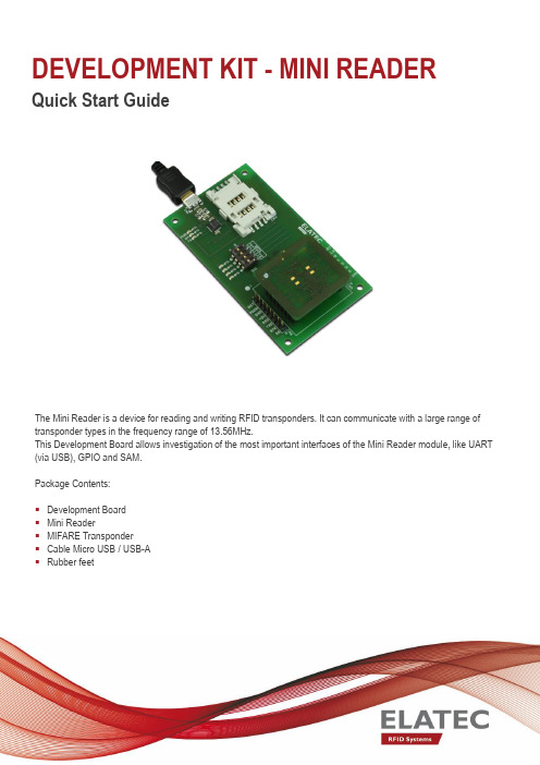
DEVELOPMENT KIT -MINI READER Quick Start GuideThe Mini Reader is a device for reading and writing RFID transponders. It can communicate with a large range of transponder types in the frequency range of 13.56MHz.This Development Board allows investigation of the most important interfaces of the Mini Reader module, like UART (via USB), GPIO and SAM.Package Contents:▪Development Board▪Mini Reader▪MIFARE Transponder▪Cable Micro USB / USB-A▪Rubber feetElatec reserves the right to change any information or data in this document without prior notice. The distribution and the update of this document is not controlled. Elatec declines all responsibility for the use of product with any other specifications but the ones mentioned above. Any additional requirement for a specific customer application has to be validated by the customer himself at his own responsibility. Where application information is given, it is only advisory and does not form part of the specification. Disclaimer: All names are registered trademarks.Elatec GmbH Zeppelinstr.182178 PuchheimGermanyPhone: +49 89 5529961 0Fax:+49 89 5529961 129********************© 2015 Elatec GmbH –DocRev7 –12/2015Getting Started1.Connect Mini Reader To work with the Mini Reader, connect the module in the appropriate connector of theDevelopment Board.IMPORTANT: Please be sure to connect the module in the right way (the marking for pin 1 ofDevelopment Board and Mini Reader should match). Otherwise the Mini Reader could bedestroyed!2. Cable Connection In order to start operating a Mini Reader, it simply has to be connected to a host. Plug in the USBCable with the Mini USB plug to the Development Board and the other one to a PC.3. Power Up Once the Board is connected to the host, a driver must be installed. If this is not doneautomatically, you can download the driver for your operating system on the FTDI website:/Drivers/VCP.htmWhen the driver installation is finished, a new virtual COM port is installed on the PC. Now youcan set up a connection to the Mini Reader using this COM port.4. Operation Mini ReaderThe easiest way to communicate with the Mini Reader is the software SmartISO.exe which youcan find in the MifareNFCDevPack107. You can download the DevPack at:/download-centerTo setup a serial connection to the reader, just select the previously installed virtual COM port(see 3.3), set the baud rate to 9600 and click the button Connect.Once the serial connection is established, you can click Start on the tab Read Serial Numbers.TWN4 MultiTech HF Mini ReaderIt is very convenient to operate the TWN4 MultiTech HF Mini Reader with the Director softwaretool, which you can find in the base directory of the TWN4 DevPack.First you need to find the right COM port in the Device Manager.Select the appropriate COM port in Director and press the button Connect.After the connection is established, you can search for transponders by clicking the button Search(search once) or activate the checkbox Cycle.5. Detection of a Transponder Now just place a transponder near the Mini Reader and the SmartISO Software will show the UIDin the log window!Order Code for DevKitMini ReaderTWN4 MultiTech HF Mini Reader T3MK-F which includes Mini ReaderT4MK-F which includes TWN4 MultiTech HF Mini Reader。
易驱电气GT610GT620使用手册v1.1

接 脉冲输入接口
1 个:方向脉冲或正交脉冲,5V
口 编码器输出接口 1 个:最高接收频率 500kHz,5V
总线接口
RS485 标准
速度控制
范围:0~30000rpm;转向:正反;速度指令:模 拟量、脉冲频率
主 准停定位
精度± 1Pulse;位置调节:用户参数设定
轴 刚性攻丝
可与多种国产、进口系统接口,攻丝误差±2%
-8-
GT610/620 系列高性能主轴伺服使用说明书
数字量输入
8 路光耦隔离输入;输入方式:PNP、NPN 可选
输 数字量输出
3 路光耦隔离输出;+24V DC,50mA
入 模拟量输入 输 继电器输出
2 路:0 ~±10V 2 路:AC250V,3A;DC30V,1A
出 编码器输入接口 1 个:最高接收频率 500kHz,5V
第二章 安装尺寸 .............................................. 17 第三章 控制端子接线 .......................................... 18
3.1 驱动器端子接线定义.................................... 18 3.2 有感扩展卡端口定义.................................... 19 3.3 GT610/620 端子接线总图 ................................ 21 第四章 参数说明 .............................................. 22 4.1 F0 组-系统参数 ........................................ 22 4.2 F1 组-参数 ............................................ 23 4.3 F2 组-DI/D 电机 O 端子定义参数.......................... 25 4.4 F3 组-加减速参数 ...................................... 26 4.5 F4 组-速度环参数 ...................................... 27 4.6 F5 组-位置环参数 ...................................... 27 4.7 F6 组-AI/AO 端子参数................................... 28 4.8 F7 组-脉冲设定、电子齿轮比参数 ........................ 30 4.9 F8 组-主轴定位、传动比参数 ............................ 30 4.10 F9 组-通讯参数 ........................................ 31 4.11 显示监控参数.......................................... 33 4.12 报警故障参数.......................................... 34
miniev使用手册
miniev使用手册MINIEV是一款小巧便携的电动汽车,旨在提供环保、经济、方便的出行选择。
本使用手册将详细介绍MINIEV的功能特点、使用方法、保养注意事项等内容,以帮助用户更好地了解和操作MINIEV。
一、MINIEV简介MINIEV是一款由知名汽车制造商研发的电动汽车,采用先进的电动技术,具备出色的城市驾驶性能和环保节能的特点。
它小巧可爱,适合在城市中短途出行或者日常代步使用。
二、MINIEV的功能特点1. 电池续航能力MINIEV搭载高性能锂电池,提供长达XXX公里的续航能力。
用户在充电后,可以轻松行驶城市中的各类交通短途,满足日常出行需求。
2. 操控灵活MINIEV采用电动方式驱动,具备优秀的悬挂系统和灵敏的转向系统,使驾驶者能够轻松应对城市交通中的各类情境,如窄小的街道、繁忙的拥堵等。
3. 多功能车载系统MINIEV配备了智能车载系统,包括导航、音频播放、蓝牙连接等功能。
用户可以通过触摸屏或者语音识别操作控制系统,实现更便捷的驾驶体验。
4. 安全性能MINIEV拥有完善的安全防护系统,包括多重气囊、防抱死制动系统、电子刹车力分配等。
这些系统能够在紧急情况下保障驾驶者和乘客的安全。
三、MINIEV的使用方法1. 开机与关机在驾驶者座位旁侧找到MINIEV的启动按钮,长按3秒后,MINIEV便会启动。
同样,长按3秒可以将MINIEV关闭。
2. 档位选择MINIEV提供自动档位模式,驾驶者只需将换挡杆拨至D档,汽车便可以正常驱动。
3.加速与刹车MINIEV的加速和刹车方式与传统汽车相似。
右脚踩下刹车踏板可进行刹车,踩下加速踏板可进行加速。
4. 手刹使用MINIEV的手刹在座位旁侧的中控台上,拉起手刹杆即可使车辆停稳。
解除手刹时,将手刹杆按下即可。
5. 车灯和信号灯MINIEV的车灯和信号灯位于方向盘旁边的控制杆上。
向上推动杆可以打开远光灯,向下推动杆可以打开近光灯。
6. 充电方式MINIEV支持插电充电和无线充电两种方式。
HP Mini 说明书
HP Mini 用户指南© Copyright 2009 Hewlett-Packard Development Company, L.P.Microsoft 和 Windows 是 Microsoft Corporation 在美国的注册商标。
SD 徽标是其所有者的商标。
本文档中包含的信息如有更改,恕不另行通知。
随 HP 产品和服务附带的明确有限保修声明中阐明了此类产品和服务的全部保修服务。
本文档中的任何内容均不应理解为构成任何额外保证。
HP 对本文档中出现的技术错误、编辑错误或遗漏之处不承担责任。
第一版:2009 年 9 月文档部件号:580592-AA1产品通告本用户指南介绍大多数机型的常用功能。
您的计算机上可能未提供某些功能。
要获取《Mini 用户指南》中最新的信息,请转至 HP 网站/support。
安全警告通告警告!为避免烫伤或使笔记本计算机过热,请勿将笔记本计算机直接放在膝盖上或阻塞其通风孔。
使用时,应将笔记本计算机放置在坚固的平面上。
不要让坚硬物体(例如旁边的打印机)或柔软物体(例如枕头、毛毯或衣物)阻挡空气流通。
而且,操作时不要让交流电源适配器接触皮肤或软表面(如枕头、毛毯或衣物)。
此款笔记本计算机和交流电源适配器符合信息技术设备安全性国际标准 (IEC60950) 中规定的用户可接触的表面温度限制。
iiiiv安全警告通告目录1 使用入门使用 HP Instant Web(仅限某些机型) (2)2 了解部件识别硬件 (3)顶部组件 (3)触摸板 (3)指示灯 (4)按键 (5)前部组件 (5)右侧组件 (6)左侧组件 (7)显示屏组件 (8)底部组件 (9)无线天线 (10)其它硬件组件 (10)识别标签 (11)3 电源管理设置电源选项 (12)使用节能状态 (12)启动和退出待机模式 (12)启动和退出休眠模式 (12)使用电源使用方案 (13)查看当前的使用方案 (13)选择不同的电源使用方案 (13)自定义电源使用方案 (14)设置退出等待模式时的密码保护 (14)使用外部交流电源 (14)连接交流电源适配器 (15)使用电池电源 (15)显示电池的剩余电量 (16)放入或取出电池 (16)为电池充电 (17)v最大程度延长电池放电时间 (18)管理电池电量不足的情况 (18)识别电池电量不足的情况 (18)解决电池电量不足的情况 (19)当有外部电源时解决电池电量不足的情况 (19)当有充电的电池时解决电池电量不足的情况 (19)当没有电源时解决电池电量不足的情况 (19)当笔记本计算机无法退出休眠模式时解决电池电量不足的情况 (19)校准电池 (19)步骤 1:为电池充足电 (19)步骤 2:禁用休眠和等待模式 (20)步骤 3:为电池放电 (20)步骤 4:为电池重新充足电 (21)步骤 5:重新启用休眠和等待模式 (21)节约电池电量 (21)存放电池 (21)处理废旧电池 (21)关闭笔记本计算机 (22)4 Internet连接至有线网络 (24)连接至无线网络 (25)使用无线设备 (25)识别无线和网络状态图标 (25)使用无线控制器 (26)使用无线开关 (26)使用 HP Connection Manager 软件(仅限某些机型) (26)使用 HP Wireless Assistant 软件 (26)使用 WLAN (27)设置 WLAN (27)保护 WLAN 安全 (28)连接 WLAN (28)漫游到其它网络 (29)使用 HP Mobile Broadband(仅限某些机型) (30)插入 SIM 卡 (30)取出 SIM 卡 (31)使用 HP Mobile Broadband Setup Utility(仅限某些机型) (33)5 多媒体多媒体功能 (34)识别多媒体组件 (34)调节音量 (35)多媒体软件 (36)vi使用其他预安装的多媒体软件 (37)从 Internet 安装多媒体软件 (37)音频 (38)连接外接音频设备 (38)检查音频功能 (38)视频 (39)连接外接显示器或投影机 (39)网络摄像机 (40)6 安全保护保护笔记本计算机 (41)使用密码 (41)在 Windows 中设置密码 (42)在设置实用程序中设置密码 (42)管理员密码 (43)管理管理员密码 (43)输入管理员密码 (43)开机密码 (43)管理开机密码 (44)输入开机密码 (44)使用防病毒软件 (45)使用防火墙软件 (46)安装重要的更新程序 (47)7 数字卡插入数字卡 (48)停止使用并取出数字卡 (49)8 USB 设备使用 USB 设备 (50)连接 USB 设备 (50)停止并移除 USB 设备 (50)9 指点设备和键盘设置指点设备首选项 (52)使用指点设备 (52)使用触摸板 (52)连接外接鼠标 (52)使用键盘 (52)使用热键 (52)启动待机模式 (53)切换屏幕 (54)降低屏幕亮度 (54)vii提高屏幕亮度 (54)启动 QuickLock (54)启用扬声器静音 (54)降低扬声器音量 (54)提高扬声器音量 (55)10 驱动器识别安装的驱动器 (56)移动驱动器 (56)使用外接驱动器 (57)使用可选外接设备 (57)11 内存模块12 更新软件更新 BIOS (62)确定 BIOS 版本 (62)下载 BIOS 更新程序 (62)更新程序和驱动程序 (64)13 更改 Instant Web 设置禁用和启用 Instant Web (65)14 设置实用程序启动设置实用程序 (66)使用设置实用程序 (66)更改设置实用程序的语言 (66)在设置实用程序中进行浏览和选择 (66)显示系统信息 (67)恢复设置实用程序中的默认设置 (67)退出设置实用程序 (67)设置实用程序菜单 (67)主菜单 (68)安全保护菜单 (68)系统配置菜单 (68)诊断菜单 (69)索引 (70)viii1使用入门HP 笔记本计算机的主要操作系统是 Microsoft® Windows®。
mini车载说明书

MINI-MDVRShenzhen Technology Co., Ltd.版权所有侵权必究All rights reserved目录1产品介绍 (3)1.1产品概述 (3)1.2产品的主要功能 (3)1.3性能参数 (3)2操作说明 (5)2.1前面板 (5)2.2后面板............................................................................................ 错误!未定义书签。
2.3遥控器 (5)3基本操作手册............................................................................................. 错误!未定义书签。
3.1系统的开启与登陆.......................................................................... 错误!未定义书签。
3.1.1系统开启 ........................................................................................ 错误!未定义书签。
3.1.2系统登陆 ........................................................................................ 错误!未定义书签。
3.2系统的查询与设置.......................................................................... 错误!未定义书签。
3.2.1设备操作 ........................................................................................ 错误!未定义书签。
mini-pro 用户手册说明书
用户手册文件编号:RGB-RD-UM-mini-pro C000版本:V1.0目录声明 (4)第一章产品简介 (6)1.1随附配件 (6)1.2产品概述 (7)1.2.1主要特点 (7)1.2.2前面板图示 (8)1.2.3接口面板图示 (9)1.2.4外形尺寸图 (10)第二章产品安装 (11)2.1连接电源 (11)2.2连接信号源 (11)2.3连接监看设备 (12)2.4连接麦克风和外接监听设备 (12)2.5连接USB作为网络信号源 (13)2.6连接计算机 (13)2.7打开mini-pro (14)第三章产品使用 (15)3.1触摸屏操作 (15)触摸屏简介 (15)划屏功能 (15)预设调用菜单 (16)3.2信号直切 (16)设置切换特效 (16)设置切换时长 (17)3.3信号预监切换与多画面分割监看 (17)3.4画中画设置 (17)设置画中画布局 (18)设置图层大小 (18)3.4预设场景的保存和快捷调用 (18)3.5视频输出设置 (19)HDMI输出 (19)USB输出 (20)3.6音频设置 (21)3.7抠图设置 (22)3.8PTZ控制与预设位置保存 (23)3.9连接USB进行硬盘录制 (24)第四章网络推流 (26)4.1OBS推流 (26)4.2VMix推流 (30)4.3钉钉直播 (31)4.4腾讯会议直播 (32)4.5飞书会议直播 (33)第5章XPOSE mini软件操作 (35)5.1.连接mini与电脑 (35)使用网线直接连接 (35)使用静态直连 (36)使用路由器无线连接 (37)5.2使用XPOSE mini (38)搜索设备 (38)PTZ摄像头设置 (39)色度抠图 (40)测试模式 (40)密码保护 (41)T-Bar校正 (41)流媒体 (42)5.3升级指导 (43)第六章订购编码 (45)6.1产品编码 (45)第七章附录 (46)7.1规格 (46)7.2FAQ (47)7.3术语和定义 (48)7.4修订记录 (54)第八章技术支持 (55)首先感谢您选购我们的产品!为了让您迅速掌握如何使用这款创意拼接器,我们为您送上了详细的产品使用手册。
易驱MINI机说明书
MINI系列变频器使用说明书(V1.0)深圳市易驱变频技术有限公司地址:深圳市福田区八卦三路光纤工业小区3栋8楼前言感谢您使用深圳市易驱变频技术有限公司生产的MINI系列高性能矢量控制变频器。
MINI系列变频器是深圳市易驱变频技术有限公司在ED3100系列的基础上开发的一款小体积变频器。
具有电机参数自辩识、模拟量电流输出、开关量输出、RS485通讯等一系列实用、先进的功能。
为设备制造商和终端客户提供了集成度高的一体化解决方案,对降低系统的采购和运营成本、缩小设备体积具有极大的帮助。
在使用变频器之前,请仔细阅读使用说明书,以确保能正确安装和操作、使变频器发挥其最佳性能,本说明书描述不够详细的地方可参阅我公司ED3100系列说明书。
本说明书如有改动,请以新版为准,恕不另行通知。
读者对象本使用说明书适合以下人员阅读变频器安装人员、工程技术人员(电气工程师、电气操作工等),设计人员本书约定符号约定注意由于没有按要求操作,可能造成中等程度伤害或轻伤的场合。
危险由于没有按要求操作,可能造成死亡或重伤的场合。
-目录-第一章概要1.1 产品确认-------------------------------------------------(5)1.2 安全注意事项-------------------------------------------(6)1.3 使用注意事项-------------------------------------------(8)第二章产品安装及配线2.1 变频器系列型号----------------------------------------(9)2.2 产品技术规范-------------------------------------------(9)2.3 外型尺寸-------------------------------------------------(10)2.4 变频器的安装环境-------------------------------------(10)2.5 变频器配线的注意事项-------------------------------(11)2.6 基本运行配线图----------------------------------------(12)2.7 端子功能说明-------------------------------------------(14)2.8 键盘的使用说明----------------------------------------(15)第三章功能参数表3.1 表中符号说明-----------------------------------------(17)3.2 功能参数表--------------------------------------------(17)第四章参数使用详细说明4.1 基本运行参数组(P0.00-P0.23)------------------(30)4.2 电机与矢量控制参数组(P1.00-P1.15)---------(37)4.3 辅助运行参数组(P2.00-P2.43)------------------(39)4.4 用户管理界面参数组(P3.00-P3.09)------------(46)4.5 开关量输入输出参数组(P4.00-P4.16)---------(47)4.6 模拟输入输出参数组(P5.00-P5.16---------------(55)4.7 过程PID控制参数组(P6.00-P6.14)--------------(59)4.8 可编程运行参数组(P7.00-P7.18)-----------------(63)4.9 通讯参数组(P8.00-P8.04)--------------------------(68)4.10保护参数(P9.00-P9.03)----------------------------(69)4.11高级功能参数(PA.00-PA.06)---------------------(71)第五章故障诊断及处理5.1 故障现象及对策-------------------------------------------(73)故障代码以及对策-----------------------------------------(73)第六章保养和维护6.1 日常保养及维护--------------------------------------------(75)6.2 定期保养及维护--------------------------------------------(75)6.3 变频器的保修-----------------------------------------------(75)第一章概要1.1 产品确认开箱时,请认真确认:在运输中是否有破损或刮伤损坏现象,本机铭牌的额定值是否与您的订货要求一致。
易驱MINI机说明书

MINI系列变频器使用说明书(V1.0)深圳市易驱变频技术有限公司地址:深圳市福田区八卦三路光纤工业小区3栋8楼前言感谢您使用深圳市易驱变频技术有限公司生产的MINI系列高性能矢量控制变频器。
MINI系列变频器是深圳市易驱变频技术有限公司在ED3100系列的基础上开发的一款小体积变频器。
具有电机参数自辩识、模拟量电流输出、开关量输出、RS485通讯等一系列实用、先进的功能。
为设备制造商和终端客户提供了集成度高的一体化解决方案,对降低系统的采购和运营成本、缩小设备体积具有极大的帮助。
在使用变频器之前,请仔细阅读使用说明书,以确保能正确安装和操作、使变频器发挥其最佳性能,本说明书描述不够详细的地方可参阅我公司ED3100系列说明书。
本说明书如有改动,请以新版为准,恕不另行通知。
读者对象本使用说明书适合以下人员阅读变频器安装人员、工程技术人员(电气工程师、电气操作工等),设计人员本书约定符号约定注意由于没有按要求操作,可能造成中等程度伤害或轻伤的场合。
危险由于没有按要求操作,可能造成死亡或重伤的场合。
-目录-第一章概要1.1 产品确认-------------------------------------------------(5)1.2 安全注意事项-------------------------------------------(6)1.3 使用注意事项-------------------------------------------(8)第二章产品安装及配线2.1 变频器系列型号----------------------------------------(9)2.2 产品技术规范-------------------------------------------(9)2.3 外型尺寸-------------------------------------------------(10)2.4 变频器的安装环境-------------------------------------(10)2.5 变频器配线的注意事项-------------------------------(11)2.6 基本运行配线图----------------------------------------(12)2.7 端子功能说明-------------------------------------------(14)2.8 键盘的使用说明----------------------------------------(15)第三章功能参数表3.1 表中符号说明-----------------------------------------(17)3.2 功能参数表--------------------------------------------(17)第四章参数使用详细说明4.1 基本运行参数组(P0.00-P0.23)------------------(30)4.2 电机与矢量控制参数组(P1.00-P1.15)---------(37)4.3 辅助运行参数组(P2.00-P2.43)------------------(39)4.4 用户管理界面参数组(P3.00-P3.09)------------(46)4.5 开关量输入输出参数组(P4.00-P4.16)---------(47)4.6 模拟输入输出参数组(P5.00-P5.16---------------(55)4.7 过程PID控制参数组(P6.00-P6.14)--------------(59)4.8 可编程运行参数组(P7.00-P7.18)-----------------(63)4.9 通讯参数组(P8.00-P8.04)--------------------------(68)4.10保护参数(P9.00-P9.03)----------------------------(69)4.11高级功能参数(PA.00-PA.06)---------------------(71)第五章故障诊断及处理5.1 故障现象及对策-------------------------------------------(73)故障代码以及对策-----------------------------------------(73)第六章保养和维护6.1 日常保养及维护--------------------------------------------(75)6.2 定期保养及维护--------------------------------------------(75)6.3 变频器的保修-----------------------------------------------(75)第一章概要1.1 产品确认开箱时,请认真确认:在运输中是否有破损或刮伤损坏现象,本机铭牌的额定值是否与您的订货要求一致。
Fujitsu U-Scan Mini-Express 自助结算机器人系列介绍说明书
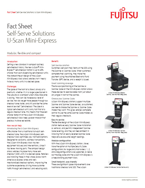
IntroductionSetting a new standard in compact cashlessself-checkout kiosks, the new U-Scan® Mini-Express™ self-checkout station is up to 40% smaller than cash dispensing self-checkout units; the state-of-the-art design of the U-ScanMini-Express kiosk allows retailers to fi t nearly twice as many units in a desired space. ChallengesThe space at the front of a store is always at a premium, whether it’s in a large supermarket in the suburbs or a compact urban store. Everyone is asking, “How can we increase our level of service; how do we get more people through our checkout lanes faster, and still provide the same level of service?” Self-checkout. The size of a typical self-checkout unit is only half that of a regular checkout lane, this means that the even smaller footprint of the U-Scan Mini-Express self-checkout kiosk frees up even more of that precious in-store real estate.How we can helpIntroducing the U-Scan Mini-Express40% smaller than a traditional full-cash self-checkout lane, the U-Scan Mini-Express self-checkout kiosk optimizes your front-end options. Designed for card-only,cashless transactions, the U-Scan Mini-Express kiosk has few equipment failures and interventions, since it has fewer moving parts. The compact design allows retailers to place many more self-checkout (SCO) units in a desired space. Retailers are installing these in their stores across North America as express lanes and well-merchandised checkout options, improving the customer experience, driving more customer traffi c through self-checkout, and reducing costs.BenefitsSelf-Service solutionCustomers self-scan their items at the SCO usingthe Scanner or Scanner Scale. When customerscomplete their scanning, they make thepayment using the attached Electronic FundTransfer (EFT) device, and a receipt is issued.Great scanning coverageThe forward positioning of the Scanner orScanner Scale on the Mini-Express station allowsthese devices to read ba rc odes from just aboutany angle in front of the scanner.Choose your Scanner ScaleU-Scan Mini-Express stations support multipleScanner and Scanner Scale devices, so customersare free to choose the Scanner or Scanner Scalemodel they want. This gives retailers completecontrol to use the same Scanner Scale models astheir regular checkouts.Easy to serviceThe flexible design of the U-Scan Mini-Expressstation features easy Scanner Scale installationor removal, and permits independent ScannerScale level l ing, and they can feel confident inknowing that an easily-level l ed Scanner Scalehelps ensure accurate weight readings.Modular configurationWith the U-Scan Mini-Express station, storeshave the option of multiple Security Scaleconfigurations for large and small orders; 1, 2,and 4 bag configurations are supported, or leaveout the bag scale and the U-Scan Mini-Express isa free-standing payment kiosk.Small footprint, user-friendlyThere are significant space improvements overtraditional checkout and SCO. The U-ScanU-Scan Mini-Express (Bioptic-Scanner, Side Mounted 2-Bag Scale)U-Scan Mini-Express (Vertical-Scanner, Front Mounted 1-Bag Scale)U-Scan Mini-Express (Vertical Scanner only)Fact SheetSelf-Serve Solutions U-Scan Mini-ExpressModular, fl e xible and compactMini-Express kiosk is also very user-friendly, providing simple transaction flows with easy-to-follow on-screen buttons that guide customers through the simple checkout process.Lower Total Cost of Ownership (TCO)The U-Scan Mini-Express stations is an inexpensive self-checkout solution that features low maintenance costs, along with reduced labor costs because there is no requirement for cash replenishing or accounting. The U-Scan Mini-Express kiosk has few moving parts, which results in a longer life without the need for repair.Business benefitsU-Scan Mini-Express stations deliver a number of key business benefits: an enhanced customer experience, a reduction in queues, more available time for value-added activities, increased revenue as customer retention levels rise, and short delivery lead times.With the new smaller size, more SCO units can fit in a single store, contributing to greater overall customer flow. Four U-Scan Mini-Express units can fit in the space of one regular POS lane, which gives stores more flexible layout choices as well as more space for merchandising and advertising. Its sleek modern design will enhance any decor.Major components■Fujitsu TeamPOS® 7000 A-Series All In One (AIO)•Intel® CPU (Haswell)•4 GB RAM•500 GB Hard Disk - incorporated 15-inch PCAP (projected capacitive)touch screen•Multiple powered and unpowered USB and serial ports•E asy to service (swing out hinge), change connections,or replace•Touch display■Scanning•H igh performance imaging via default Bioptic Scanner Scale oroptional Vertical scanner.■Printing•High speed 3.15 in. (80mm) receipt printer•Sliding printer tray makes the printer easy to access■Payment•E FT pinpad and card reader can be mounted on the left or right side •Top-mounted Scanner Scale Pole Display (Canada)■Signal Tower•High bright 3-lens signal tower on mounted pole■Casing•S lim casing features ergonomic placement of Scanner Scale and bagscale, with eye-pleasing contours that will enhance any retail decor.Available in the Fujitsu Ocean Black color scheme.■Bagging Scale• Optional Bag Scale, left, right or front attach: connect one one or more bag scale modules for increased capacity■Assist Shelf•Optional Assist shelf that can be attached on the left or right■Installation•S ecure self-standing on a strong support base; through-basefixing bolts (optional)■Customer-Specific Configuration•Customer configurations and accessories subject to confirmation Technical Details■Operating System•Microsoft® Windows® Embedded POSReady 7 or POSReady 2009■Audio•I nternal audio amplifier and front-mounted dual speakersprovide high quality sound at volume levels that are well suited toa store environment■Network•LAN (standard)■Power Supply•120 V AC■Operating Environment•Temperature: 32° to 104° F (0° to 40° C)■Dimensions (Bioptic model)•U-Scan Mini-Express with Side-Mounted 2-Bag Scale:H x W x D: 49.5 x 41.5 x 25.2 in. (1,258.3 x 1,054.9 x 640 mm)ContactFujitsu Australia LimitedHead Office 118 Talavera Rd, Macquarie Park, NSW 2113 +*****************************.com。
MiniRAE 3000操作使用手册2010.10
MiniRAE 3000 操作使用手册
Rev. C 2010 年 10 月 P/N 059-4020-C00
FCC Part 15 声明及 CE 本设备包括 FCC ID:PI4411B,符合 FCC 第 15 部分的规定。 (1)本设备不会造成破坏干扰; (2)本设备能够允许任何接收到的干扰,包括非法操作。
© Copyright 2010 RAE Systems, Inc.
目录
使用前须知 ................................................................................................................................1 注 意..........................................................................................................................................1 特别提示 ....................................................................................................................................1 警 告..........................................................................................................................................1 标准配置 ....................................................................................................................................2 产品概述 ....................................................................................................................................2 主要部件 ....................................................................................................................................2 技术指标 ....................................................................................................................................3 检测范围及分辨率.....................................................................................................................3 电池充电 ....................................................................................................................................4
U-mini-16.3说明书
U-mini-V2.0飞控说明书U-mini飞控为U100的升级换代产品,主要升级内容:1、升级自动油门(定高定向模式下,以当前油门为基准,掉高自动加油,返航模式以最低油门为准,掉高自动加油)2、自动锁定回家位置(当飞控第一次达到8颗以上的时候,自动保存当前位置为回家位置。
)3、自动滑降(平衡模式下,油门很小,会自动低头,避免失速)4、全自动失控保护。
输入通道不动,手动、3D模式5秒,平衡模式15秒,定高定向模式30秒,飞控自动转入返航模式,通道变化,解除失控保护。
(这个功能用户可以关闭)(5、增加支持切糕433的PPM3线连接接收机(3根线连接,使用方便)6、摇杆设定参数7、增加在线升级功能,用户自己升级新版本程序8、增加3级最低返航高度设置(70,140,210米)。
高于这个最低设定高度,飞机按照实际高度返航,低于这个高度,则飞机爬升到最低高度返航,这个可以避免过低返航,导致碰撞9、改进微分法3D飞行模式。
3D模式下花式飞行飞行更稳定、轻松、自如。
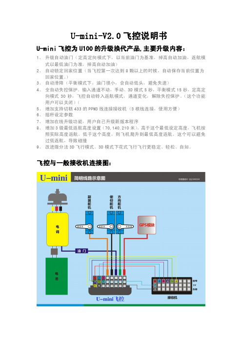
飞控与一般接收机连接图:飞控与接收机连接说明:一、连接接收机的1-6通道,分别控制:1-副翼通道2-俯仰通道3-油门4-方向通道5-二段开关通道6-三段开关通道U-MINI接线图:二、连接切糕433串行3线连接模式(U-MINI接线图中白色的3根线部分):(3)PPM信号5V PPM的5V电源地线PPM的地线双天线切糕接收机连接方法:单天线切糕接收机连接方法:3个电位器分别控制3个方向上的反馈正反与反馈幅度(反馈电位器中间位最小,两侧分开为正负两个方向)飞控调节步骤:安装:将飞控水平放置于飞机上(尽量靠近重心位置),飞控头部向前(按照说明的箭头方向放置)。
飞控最好采取一定的减震措施,最好是皮筋悬空或加海绵减震。
输入端口的副翼、平尾、油门、垂尾、三段开关、二段开关连接到遥控器接收机相应通道上。
调试:(请严格按照1-6的以下步骤调试)1:调节飞控反馈方向和幅度。
Bosch 迷你撩饼机用户手册说明书
m i tWe c h s e l s t r oma n g e s c h l o s s e nwe r d e n.S t e l l e nS i es i c h e r,d a s sd a sS c h u t z l e i t e r s y s t emd e r e l e k t r i s c h e nHa u s i n s t a l l a t i o n v o r s c h r i f t smäßi g i n s t a l l i e r t i s t.Ge rät n u r g emäßAn g a b e na u fd e m T y p e n s c h i l da n s c h l i eße nu n db e t r e i b e n.Nu r b e n u t z e n,we n nZ u l e i t u n gu n dGe rät k e i n eBe s c häd i g u n g e na u f we i s e n.S t e c k e rn a c h j e d emGe b r a u c ho d e r i mF e h l e r f a l l z i e h e n.Re p a r a t u r e namGe rät,w i ez.B.e i n eb e sc häd i g t eZ u l e i t u n ga u swe c h s e l n,dürf e n n u rd u r c hu n s e r e nKu n d e nd ie n s t a u s g e füh r twe r d e n,umGe fäh r d u n g e nz uv e r me i d e n.K i n d e r u n t e r8J a h r e ns i n dv omGe rät u n dd e r A n s c h l u s s l e i t u n gf e r n z u h a l t e nu n ddür f e nd a sGe rät n i c h t b e d i e n e n.D i e s e s G e rätk a n nv o nK i n d e r na b8J a h r e nu n dd a rübe r u n dv o nPe r s o n e nm i tr e d u z i e r t e np h y s i s c h e n,s e n s o r i s c h e no d e rme n t a l e nFäh i g k e i t e no d e rMa n g e l a nE r f a h r u n gu n d/o d e rW i s s e nb e n u t z twe r d e n,we n ns i eb e a u f s ic h t i g t ode r b e züg l i c hd e sGe b r a u c h sd e sGe rät e su n t e r w i e s e nwu r d e nu n dd i ed a r a u s re s u l t i e r e n d e nGe f a h r e nv e r s t a n d e nh a b e n.K i n d e r dür f e nn i c h tm i t d emGe rät s p i e l e n.Re i n i g u n gu n dBe n u t z e r-Wa r t u n gdür f e nn i c h t d u r c hK i n d e rv o r g e n omme nwe r d e n,e ss e i d e n n,s i es i n d8J a h r eo d e räl t e r u n dwe r d e nb e a u f s ic h t i g t.WV e r b r e n n u n g s-u n dB r a n d g e f a h r!Ge rät n i c h t a uf o d e r i nd i eNäh eh e iße rOb e r fläc h e n,w i ez.B.He r d p l a t t e n,s t e l l e n.F e t t s p r i t z e r v e r h i n d e r n,d e rKu n s t s t o ffk a n nb e sc häd i g twe r d e n.F e h l a nwe n d u n gd e sGe rät e sk a n nz uV e r l e t z u n g e n füh r e n.Ge rätn i ema l sa nZ e i t s c h a l t u h r e no d e r f e r n b e d i e n b a r eS t e c k d o s e na n s c h l i eße nu n db e t r e i b e n.a b küh l e n l a s s e n.Da sGe rät o d e rNe t z k a b e l n i ema l s i nWa s s e rt a u c h e n o d e r i nd e nGe s c h i r r s pül e r g e b e n.Ke i n e nDamp f r e i n i g e rb e n u t z e n.N i c h tm i tBa c k o f e n-/G r i l l s p r a y r e i n i g e n.K rüme lu n t e r d e m B röt c h e n a u f s a t zm i t e i n emh a r t e nP i n s e l e n t f e r n e n.K rüme l s c h u b l a d eh e r a u s z i e h e nu n da b w i s c h e n.T o a s t e rn u r s t e h e n db e t r e i b e n.De nT o a s t e rwäh r e n dd e sBe t r i e b ss t e t sb e a u f s ic h t i g e n!KWARNUNG:D i e s e sGe rät n i c h t i nd e rNäh ev o nBa d ewa n n e n,Du s c h e n,Wa s c hb ec k e no d e r a n d e r e nGe fäße nb e n u t z e n,d i eWa s s e r e n t h a l t e n.WE r s t i c k u n g s g e f a h r!K i n d e r n i c h tm i tV e r p a c k u n g sma t e r i a l s p i e l e n l a s s e n.。
LAURUS MINI Z系统产品介绍说明书

A D V A N C E D T E C H N O L O G Y F O R A S A F E R W O R L DLAURUS Systems, Inc. - Ph: 410-465-5558 - Fax: 410-465-5257 - The MINI Z® system is the world’s most powerful Z Backscatter® imaging system, highlighting organic threats and contraband and providing unsurpassed operational flexibility.With its small form factor and single-sided imaging, the MINI Z system can scan a wide variety of targets, such as car doors and fenders; tires; furniture; packages; and the interiors of boats, vehicles and aircraft. The MINI Z system is completely self-contained, with no required set-up and no consumables to replenish. Simply power on the device and you’re ready to scan. The MINI Z system is inherently low dose and features reliable and redundant safety subsystems.The Enhanced Detection Panel option for the MINI Z system provides operators with the ability to detect more threats by providing more information about scanned objects. Using the Enhanced Detection Panel, operators can select to acquire a transmission image of the object to detect metallic threats, such as guns andknives. The transmission image is displayed on the tablet simultaneously with the Z Backscatter image.FEATURES AND BENEFITS• Portable Z Backscatter imaging system • Easy to use• Safe for operators, bystanders and the environmentLEFT: MINI Z system scanning passenger door RIGHT: X-ray image of concealed currencyMINI ZHandheld BackscatterScreening SystemLAURUS Systems, Inc. - Ph: 410-465-5558 - Fax: 410-465-5257 - MINI ZSystem Specifications• X-ray Source: 10-watt 120 keV X-ray tube• Interconnection Options: Wireless connection through built-in Wi-Fi; optional hard-wire via Ethernet cableScanner Dimensions• Length: 11.5 in (29.2 cm) • Width: 9.8 in (24.9 cm) • Height: 7.6 in (19.3 cm) • Weight: 11 lbs (5 kg)Operating Time• Scanner Battery: Four hours (typical) per battery; two batteriesprovided• Scan Speed: Nominal 15 cm (6 in) per second • Tablet Battery: Six hours, typical• System Software: Microsoft ® Windows ® 1O IoT with ASEInspection ™softwareTransport Case Dimensions• Length: 25 in (63.5 cm) • Width: 19.5 in (49.5 cm) • Height: 15.0 in (38.1 cm)• Full System Weight: 49.8 lbs (22.6 kg)Environment• Operating Temperature: -4° F to 113° F (-20° C to 45° C) • Storage Temperature: -40°F to 140° F (-40° C to 60° C)• Operable in: Rain, snow, high winds, and altitudes up to 9,845 ft (3,000 m)nominally• In Compliance With: CE directive 2004/108/ECHealth and Safety• Complies fully with all applicable U.S. federal health and safety regulations:• ANSI/HPS N43.3–2008 Open System Classification• Conforms to applicable ANSI, ICRP, NCRP, and Euratom radiation safety standards for annual allowable dose for the generalpublic• To help prevent inadvertent X-ray emission, the system is equipped with a series of interlocks and audiovisual indicators • Contains no live radiation sourceSystem Components• MINI Z scanner• Microsoft Windows 1O IoT tablet withASE Inspection software• Rugged tablet case with integrated stand • Tablet mount to affix to MINI Z system • Two replaceable batteries• Battery charger (with international powercords)• Transport case • Warmup dock • Quick-start guideSystem Options• Tactical Backpack : For greaterportability• Enhanced Detection Panel: Providesoperators with the ability to acquire transmission images• Language Kits: Arabic, Chinese, English(standard), French, Polish, Portuguese, Russian, Spanish。
- 1、下载文档前请自行甄别文档内容的完整性,平台不提供额外的编辑、内容补充、找答案等附加服务。
- 2、"仅部分预览"的文档,不可在线预览部分如存在完整性等问题,可反馈申请退款(可完整预览的文档不适用该条件!)。
- 3、如文档侵犯您的权益,请联系客服反馈,我们会尽快为您处理(人工客服工作时间:9:00-18:30)。
MINI系列变频器使用说明书(V1.0)深圳市易驱变频技术有限公司地址:深圳市福田区八卦三路光纤工业小区3栋8楼前言感谢您使用深圳市易驱变频技术有限公司生产的MINI系列高性能矢量控制变频器。
MINI系列变频器是深圳市易驱变频技术有限公司在ED3100系列的基础上开发的一款小体积变频器。
具有电机参数自辩识、模拟量电流输出、开关量输出、RS485通讯等一系列实用、先进的功能。
为设备制造商和终端客户提供了集成度高的一体化解决方案,对降低系统的采购和运营成本、缩小设备体积具有极大的帮助。
在使用变频器之前,请仔细阅读使用说明书,以确保能正确安装和操作、使变频器发挥其最佳性能,本说明书描述不够详细的地方可参阅我公司ED3100系列说明书。
本说明书如有改动,请以新版为准,恕不另行通知。
读者对象本使用说明书适合以下人员阅读变频器安装人员、工程技术人员(电气工程师、电气操作工等),设计人员本书约定符号约定注意由于没有按要求操作,可能造成中等程度伤害或轻伤的场合。
危险由于没有按要求操作,可能造成死亡或重伤的场合。
-目录-第一章概要1.1 产品确认-------------------------------------------------(5)1.2 安全注意事项-------------------------------------------(6)1.3 使用注意事项-------------------------------------------(8)第二章产品安装及配线2.1 变频器系列型号----------------------------------------(9)2.2 产品技术规范-------------------------------------------(9)2.3 外型尺寸-------------------------------------------------(10)2.4 变频器的安装环境-------------------------------------(10)2.5 变频器配线的注意事项-------------------------------(11)2.6 基本运行配线图----------------------------------------(12)2.7 端子功能说明-------------------------------------------(14)2.8 键盘的使用说明----------------------------------------(15)第三章功能参数表3.1 表中符号说明-----------------------------------------(17)3.2 功能参数表--------------------------------------------(17)第四章参数使用详细说明4.1 基本运行参数组(P0.00-P0.23)------------------(30)4.2 电机与矢量控制参数组(P1.00-P1.15)---------(37)4.3 辅助运行参数组(P2.00-P2.43)------------------(39)4.4 用户管理界面参数组(P3.00-P3.09)------------(46)4.5 开关量输入输出参数组(P4.00-P4.16)---------(47)4.6 模拟输入输出参数组(P5.00-P5.16---------------(55)4.7 过程PID控制参数组(P6.00-P6.14)--------------(59)4.8 可编程运行参数组(P7.00-P7.18)-----------------(63)4.9 通讯参数组(P8.00-P8.04)--------------------------(68)4.10保护参数(P9.00-P9.03)----------------------------(69)4.11高级功能参数(PA.00-PA.06)---------------------(71)第五章故障诊断及处理5.1 故障现象及对策-------------------------------------------(73)故障代码以及对策-----------------------------------------(73)第六章保养和维护6.1 日常保养及维护--------------------------------------------(75)6.2 定期保养及维护--------------------------------------------(75)6.3 变频器的保修-----------------------------------------------(75)第一章概要1.1 产品确认开箱时,请认真确认:在运输中是否有破损或刮伤损坏现象,本机铭牌的额定值是否与您的订货要求一致。
如发现有不良情况请与供货商或直接与我公司联系。
变频器型号说明:图1-1变频器型号说明在变频器机箱的右侧板下方,贴有标示变频器型号及额定值的铭牌,内容如下:图1-2变频器铭牌1.2 安全注意事项●安装●接线保养、检查1.3 使用注意事项1.3.1、 在50Hz以上频率运行若超过50Hz运行,除了考虑电机的振动、噪音增大外,还必须确保电机轴承及机械装置的使用速度范围,务必事先查询。
1.3.2、 海拔高度与降额使用在海拔高度超过1000米的地区,由于空气稀薄造成变频器的散热效果变差,有必要降额使用。
如图1-3所示为变频器的额定电流与海拔高度的关系曲线。
I图1-3无 变频器额定输出电流与海拔高度降额使用图1.4、关于防护等级ED3100系列MINI型变频器的防护等级IP20是指在使用状态或键盘显示情况下达到的。
第二章产品安装及配线2.1 变频器系列型号MINI系列变频器有220V和380V两种电压等级。
适配电机功率范围为:0.4KW~1.5KW。
MIN系列变频器的型号电压等级 变频器型号 额定输出电流(A) 适配电机(KW) MINI-4T0004M 1.5 0.4MINI-4T0007M 2.3 0.75 380VMINI-4T0015M 3.7 1.5MINI-2S0004M 3.0 0.4MINI-2S0007M 5.0 0.75 220VMINI-2S0015M 7.5 1.52.2 产品技术规范项目 标准规范输入电压 单相220V、三相 380V;50Hz/60Hz输入变动容许值 电压:-20% ~ +20% 电压失衡率:<3%额定电压 0~220V/0~380V输出频率范围 0Hz~400Hz调制方式 优化空间电压矢量PWM控制方式 无速度传感器矢量控制频率精度 数字设定:最高频率×±0. 01%;模拟设定:最高频率×±0.2%频率分辨率 数字设定:0.01Hz;模拟设定:最高频率×0.1%转矩提升 自动转矩提升,手动转矩提升1%~30.0%(V/F模式)V/F曲线 线性V/F曲线、平方V/F曲线、用户自定义V/F曲线内置PID 方便地构成闭环控制系统,适用于压力、流量控制多段速运行 通过内置PLC或控制端子实现多段速运行转矩特性 1HZ时输出额定转矩的150%,转速稳定精度0.1%电机参数自辨识 在电机完全静止的情况下自动辨识电机参数,以获得最佳控制效果运行命令通道 操作面板给定;控制端子给定;串行口给定;可三种方式切换频率设定通道 键盘电位器给定;键盘▲、▼键给定;数字给定;串行给定;端子UP/DOWN给定;模拟信号给定;组合给定开关输入通道 正、反转指令;6路可编程开关量输入,最多可设定30种功能。
模拟输入通道 2路模拟信号输入,0~20mA、0~10V可选模拟输出通道 模拟信号输出0~10V、0~20mA可选开关量输出通道 3路可编程开路集电极输出;1路继电器输出信号;LED数码显示 可显示设定频率、输出电压、输出电流等参数保护功能 过流保护;过压保护;欠压保护;过热保护;过载保护等2.3 外形尺寸(MINI-S型)(MINI-L型)变频器外形及安装系列尺寸规格 W W1 H H1 H2 D D1 D2 D3RMINI-S85 74 155******** 98 112 2.5MINI-L98 88 175******** 120 32.4 变频器的安装环境2.4.1 安装环境要求(1) 安装在通风良好的室内场所,环境温度要求在-10ºC~40ºC的范围内,如温度超过40ºC时,需外部强制散热或者降额使用。
(2) 避免安装在阳光直射、多尘埃、有飘浮性的纤维及金属粉末的场所。
(3) 严禁安装在有腐蚀性、爆炸性气体的场所。
湿度低于95%RH,无水珠凝结。
尽量远离电磁干扰源和对电磁干扰敏感的其它电子仪器设备。
(4) 安装在平面固定振动小于5.9米/秒²的场所。
2.4.2 安装方向与空间(1) 一般情况下应立式安装。
(2) 安装间隔及距离最小要求,如图2-1所示。
(3) 多台变频器采用上下安装时,中间应用导流隔板,如图2-2所示。
图2-1 安装的间隔距离图 图2-2 多台变频器的安装2.5变频器配线的注意事项 2.5.1 变频器与选配件的连接(1) 在供电电网和变频器之间,安装隔离开关等分断装置,用于在设备维修时的人身安全和强制断电。
(2) 变频器供电回路必须安装有过流保护作用的快熔丝或断路器,避免故障范围扩大。
导流隔板2.6基本运行配线图MINI-LMB图2-3基本运行配线图提示:1.AI2可以选择电压或者电流信号输入,由控制板上的三档二位开关JP1的位置切换。
2.AO1可以选择输出电压或者电流信号,由控制板上的三档二位开关JP2的位置切换。
3.以上为MINI-LMB的接线图,MINI-SMB为MINI-LMB的精简版部分功能取消,见图2-4图2-4 MINI-SMB运行配线图提示:1.AI2可以选择电压或者电流信号输入,由控制板上的三档二位开关JP1的位置切换。
2.AO1可以选择输出电压或者电流信号,由控制板上的三档二位开关JP2的位置切换。
3. MINI-SMB无DI5和DO3端子。
2.7 端子功能说明,如下表所示类别 端子标号名称 端子功能说明 规格通讯 485+485-RS485通讯接口RS485差分信号正端RS485差分信号负端标准RS485通讯接口,请使用双绞线或屏蔽线多功能输出端子 DO1DO2开路集电极输出端子可编程定义为多种功能的开关量输出端子,详见端子功能参数P4 . 07、P4 . 08输出端子功能介绍.(公共端:COM )光耦隔离输出工作电压范围:9~30V最大输出电流:50mA高速输出端子 DO3 高速光耦输出可对应输出频率、输出电流、电机转速、输出电压等物理量输出0-20KHZ的脉冲信号。
