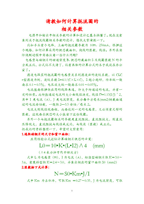
Coilcraft线艺共模扼流圈 0603USB-251MLC参数对照表
扼流圈参数

请教如何计算扼流圈的相关参数电源牛和输出牛相关参数的计算和设计已基本搞懂了。
现在没有查到关于扼流线圈相关参数的设计,想找大家请教一下。
比如手头有个电路,上面的扼流圈参数为10H、250mA,根据这个规格,如何计算采用的铁芯截面积,绕线的匝数,线径。
另外在实际绕制过程中需要注意一些什么问题?电感量与硅钢片的磁通密度B、铁芯的截面积S及线圈匝数N的平方成正比,公式记不太清了,记有具体的计算公式的本子我放在办公室了。
滤波电路里的扼流圈的电感量关系到滤波后的波纹系数,以CLC π型滤波为例,波纹系数S=4.1/(C×L×C),S越小越好,功率级一般要求0.1~0.5%,电压放大级一般要求0.01~0.05%。
电流值要根据你应用的线路来选,即大于所通过的电流,并有一定的裕量。
而所能通过电流的大小由线径决定,线径D=1.13(I/J)^2,其中I是电流(A),J是电流密度,表示每平方毫米(mm2)铜截面通过的电流安培数,一般取2—3.5安培/毫米2。
电流大则线径就要粗,而要达到一定的电感量,又必须有足够的匝数,这就要求铁芯的大小能容下这些线圈。
另外一个与扼流圈相关的参数是直流阻抗,直流阻抗大,则直流压降就大,直流阻抗与线径成反比,与线长(匝数)成正比。
把我记的资料整理一下,希望对大家有用:1.选取硅钢片的尺寸和窗口面积:应用经验公式近似计算硅钢片铁芯的舌宽:L0=10•K•(L•I2)∧4 (mm)(∧4表示括号内开四次方)式中L为电感量(H),I为电流(A),标准型硅钢片取K=3.0~3.6,有废料型取K=2.4~3.0,并查出相应的窗口面积S0(mm2)2.匝数按下式计算:N=S0•Km•J/I式中Km 为占积率,可取Km =0.27~0.35,J为电流密度,可取J=2.5~3.0A/ mm23.导线截面积可按下式计算:g=I/J (mm2)电源牛容量根据电路结构和电子管的使用如何选择?即要避免小马拉大车造成牛超负荷运行发热损坏. 也要避免大马拉小车.造成大财小用. 前提是牛要设计制作合理避免使用歪牛. 牛在正常使用中会征热是正常的, 因为铜损和铁损所耗功率转化为热能要散发. 这里有两个问题第一如何判断牛的质量?如何检测?衡量一牛的参数有哪些?第二如何正确选择马的大小即功率匹配(容量. 次级电压次级各组电流. 整流.滤波), 能系统学习一下对D1Y朋友是很有益, 本人也是老菜鸟, 但心善每伏匝数少了点吧?初级700匝/220V=3、1匝/V. 铁芯截面积32X5O=16可以做到16OW左右、初级电流160w/220V=0.7A线径按2‧5A/mm宜选0、62线径选择也太细了点吧?请教如何计算扼流圈的相关参数?一个输出变压器初级阻抗问题请教各位.一个输出变压器的初级阻抗符合这个电子管并且功率也足够,那么就可以使用在这个电路里面吗?而不必考虑是不是给这个电子管设计的吗? (假如6p3p单端用3.5k的但设计的时候功率设计的够300B的,假使300B也用3.5k的话,那么就可以直接来用吗?)功率足够当然可以用但是效果就不如专用的了不同的管子但有同样的阻抗和功率要求,同一个厂家设计时有什么不一样吗?300B是低内阻大电流10H的电感就够了6p3p是高内阻小电流要20H以上才合适所以300B的牛用在6P3P上会很差经实作,28X50,3.5K,初级0.21 2600T,次级8Ω0.8线绕133T,初5夹次4,初级每段500T,次级每段34T,次级两头用0.21绕12--13T 乱绕封口(上下贴双面胶,主要起封闭作用),层间用描图纸绝缘,段间用0.044玻璃纸和0.2电缆纸绝缘,次级稀绕初级密绕,描图纸宽度45mm,实际绕完后约42mm,电缆纸和玻璃纸42mm,对于次级圈数严格按133T,初级误差在50T无所谓,但两只变压器要对称,如果要加强低音,输出变压器可在次级80T抽头接输出管阴极,在变压器装配完成后,简单的配对可以用隔离变压器串电流表输入到初级,次级接10000Ω电阻,敲动铁心调整磁隙使电流一致,上紧螺丝浸漆烘干即可,供参考,28铁心做FU—7输出略小。
0603超小尺寸压敏电阻 - Sunlord Electronics

EXPERT IN PASSIVE PARTS0603超小尺寸压敏电阻超小尺寸,适用高密度设计高性能,优良的ESD抑制能力2011.8EXPERT IN PASSIVE PARTS 目录0603压敏电阻基本特性超小尺寸适合高密度封装高性能,优良的ESD抑制能力0603压敏电阻描述产品编号参数描述性能范围和型号对照0603压敏在电路中的应用如何选择压敏电阻器0603压敏电阻的应用手机中的应用1/11EXPERT IN PASSIVE PARTS2/11由于整机的小型化、多功能化,要求电子元件也小型化,例如高端智能手机、耳机、话筒、数据卡等产品都趋向于使用更小尺寸的被动器件。
针对这种需求,我司推出0603(0201)尺寸的压敏电阻,相比1005(0402)尺寸,可以有效减小PCB 占用面积,进一步实现整机小型化。
超小尺寸适合高密度封装78.4640.3±0.050.3±0.050.6±0.05SDV0603//0.5±0.150.5±0.151.0±0.15SDV1005体积缩小率(%)面积缩小率(%)T (mm )W (mm )L (mm )型号EXPERT IN PASSIVE PARTS3/11高性能,优良的ESD 抑制能力SDV0603压敏电阻电性能(与SDV1005比较)158331~3826SDV1005158331~3826SDV06032405~1022~2818SDV10051405~1022~2818SDV060312400.5~2100~16026SDV100512400.5~2100~16014SDV06033~102012~5011~169SDV10051~52012~5011~169SDV06033~101812~5010~145.5SDV10051~51812~5010~145.5SDV0603Peak Current 8/20μS (A )Max. Clamping Voltage (V)Cp(pF) @ 1MHz V1mA (V)Max. Vdc (V)型号EXPERT IN PASSIVE PARTS4/11高性能,优良的ESD 抑制能力SDV0603压敏电阻电性能(与同行型号比较)//0.6~0.95.85.0(Fwd )SESD0201TYCO (TVS )1015.6308.56(Fwd )SP1005-01W Littefuse (TVS )13918125.5CT0201S EPCOS 1~5/8.5~1806.8~273.7~16EZJPZV Panasonic 1~1014~2325~706.8~123.5~7.5AVRM0603TDK //4~7012.8~255.5~10AVLC-01AMOTECH 1~518~580.5~5010~385.5~26SDV0603SUNLORD Peak Current 8/20μS (A )Max. Clamping Voltage (V)Cp(pF) @ 1MHZ V 1mA (V)Max. Vdc (V)型号公司EXPERT IN PASSIVE PARTS 目录0603压敏电阻基本特性超小尺寸适合高密度封装高性能,优良的ESD抑制能力0603压敏电阻描述产品编号参数描述性能范围和型号对照0603压敏在电路中的应用如何选择压敏电阻器0603压敏电阻的应用手机中的应用5/11EXPERT IN PASSIVE PARTS6/11SDV 0603E090 C150 N PT F ①②③④⑤⑥⑦⑧⑨产品编号②尺寸代号(L ×W) (mm)0603 [0201] 0.6×0.3①类型SDV 片式压敏电阻器④最大直流工作电压Example Nominal Value 5R5 5.5V 090 9V⑧包装T 盘装⑤电容@1MHzExample Nominal Value C150 15pF C151 150pF⑥电容公差N ±30%Y +100/-50%G Maximum ③特征代号A 过电压用E ESD 防护用H 高速信号线用S 特殊要求⑦端头代号P Ni, Sn 电镀⑨无有害物质产品FEXPERT IN PASSIVE PARTS7/11参数描述V DC 直流工作电压(使用参数)压敏电阻器在最高操作温度下使用时的最大持续直流工作电压,被用来作为测试漏电流的对应电压点. 该电压总是比压敏电压小. V AC 交流工作电压(使用参数)压敏电阻器在最高操作温度下使用时的最大持续正弦交流工作电压。
美国线艺Coilcraft汽车级贴片电感0603LS 系列选型规格书

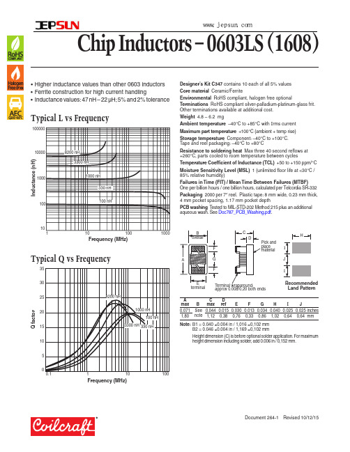
Chip Inductors – 0603LS (1608)• Higher inductance values than other 0603 inductors • Ferrite construction for high current handling• Inductance values: 47 nH – 22 µH; 5% and 2% toleranceI n d u c t a n c e (n H )10Frequency (MHz)Typical L vs FrequencyDesigner’s Kit C347 contains 10 each of all 5% values Core material Ceramic/FerriteEnvironmental RoHS compliant, halogen free optionalTerminations RoHS compliant silver-palladium-platinum-glass frit. Other terminations available at additional cost.Weight 4.8 – 6.2 mgAmbient temperature –40°C to +85°C with I rms current Maximum part temperature +100°C (ambient + temp rise)Storage temperature Component: –40°C to +100°C. Tape and reel packaging: –40°C to +80°CResistance to soldering heat Max three 40 second reflows at +260°C, parts cooled to room temperature between cyclesTemperature Coefficient of Inductance (TCL) +50 to +150 ppm/°C Moisture Sensitivity Level (MSL) 1 (unlimited floor life at <30°C / 85% relative humidity)Failures in Time (FIT) / Mean Time Between Failures (MTBF) One per billion hours / one billion hours, calculated per Telcordia SR-332Packaging 2000 per 7″ reel. Plastic tape: 8 mm wide, 0.23 mm thick, 4 mm pocket spacing, 1.17 mm pocket depthPCB washing T ested to MIL-STD-202 Method 215 plus an additional aqueous wash. See Doc787_PCB_Washing.pdf .Frequency (MHz)Q f a c t o rTypical Q vs Frequencyapprox 0.008/0,20 both endsterminalRecommended Land PatternNote: B1 = 0.040 ±0.004 in / 1,016 ±0,102 mmB2 = 0.046 ±0.004 in / 1,169 ±0,102 mmHeight dimension (C) is before optional solder application. For maximum height dimension including solder, add 0.006 in / 0,152 mm.A C D 深圳捷比信--高品质精密元件供应商www.jepsun.comChip Inductors – 0603LS SeriesInductance 2 Percent SRF min 4 DCR max 5 I rms 6Color OverallPart number 1 (nH) tolerance Q min 3 (MHz) (Ohms) (A)code width0603LS-47NX_L_ 47 @ 7.9 MHz 5,2 12 @ 7.9 MHz 1500 0.075 1.40 Black B10603LS-51NX_L_ 51 @ 7.9 MHz 5,2 12 @ 7.9 MHz 1400 0.075 1.00 Violet B10603LS-72NX_L_ 72 @ 7.9 MHz 5,2 12 @ 7.9 MHz 1400 0.12 1.40 Brown B10603LS-101X_L_ 100 @ 7.9 MHz 5,2 12 @ 7.9 MHz 1150 0.13 1.40 Red B10603LS-121X_L_ 120 @ 7.9 MHz 5,2 12 @ 7.9 MHz 1100 0.15 1.40 Orange B10603LS-151X_L_ 150 @ 7.9 MHz 5,2 15 @ 7.9 MHz 1050 0.15 1.30 Y ellow B10603LS-181X_L_ 180 @ 7.9 MHz 5,2 15 @ 7.9 MHz 950 0.15 1.30 G reen B10603LS-241X_L_ 240 @ 7.9 MHz 5,2 15 @ 7.9 MHz 800 0.16 0.95 Violet B10603LS-271X_L_ 270 @ 7.9 MHz 5,2 15 @ 7.9 MHz 775 0.30 0.71 G ray B10603LS-331X_L_ 330 @ 7.9 MHz 5,2 15 @ 7.9 MHz 725 0.46 0.56 White B10603LS-391X_L_ 390 @ 7.9 MHz 5,2 15 @ 7.9 MHz 620 0.51 0.50 Black B10603LS-471X_L_ 470 @ 7.9 MHz 5,2 15 @ 7.9 MHz 540 0.62 0.42 Brown B10603LS-561X_L_ 560 @ 7.9 MHz 5,2 15 @ 7.9 MHz 525 0.44 0.55 Red B10603LS-681X_L_ 680 @ 7.9 MHz 5,2 15 @ 7.9 MHz 260 0.52 0.47 Orange B20603LS-781X_L_ 780 @ 7.9 MHz 5,2 15 @ 7.9 MHz 460 0.83 0.39 Y ellow B10603LS-821X_L_ 820 @ 7.9 MHz 5,2 15 @ 7.9 MHz 410 0.69 0.40 G reen B10603LS-102X_L_ 1000 @ 7.9 MHz 5,2 15 @ 7.9 MHz 190 0.81 0.40 Blue B20603LS-122X_L_ 1200 @ 7.9 MHz 5,2 15 @ 7.9 MHz 160 0.87 0.37 Violet B2 0603LS-152X_L_ 1500 @ 7.9 MHz 5,2 15 @ 7.9 MHz 100 0.96 0.35 G ray B2 0603LS-182X_L_ 1800 @ 7.9 MHz 5,2 15 @ 7.9 MHz 80 1.1 0.35 White B2 0603LS-222X_L_ 2200 @ 7.9 MHz 5,2 15 @ 7.9 MHz 68 1.2 0.32 Black B2 0603LS-272X_L_ 2700 @ 7.9 MHz 5,2 15 @ 7.9 MHz 60 1.5 0.28 Brown B2 0603LS-332X_L_ 3300 @ 7.9 MHz 5,2 15 @ 7.9 MHz 42 1.5 0.28 Red B2 0603LS-392X_L_ 3900 @ 7.9 MHz 5,2 15 @ 7.9 MHz 40 1.6 0.28 Orange B2 0603LS-472X_L_ 4700 @ 7.9 MHz 5,2 15 @ 7.9 MHz 34 2.1 0.26 Y ellow B20603LS-562X_L_ 5600 @ 7.9 MHz 5,2 15 @ 7.9 MHz 32 2.6 0.24 G reen B20603LS-682X_L_ 6800 @ 7.9 MHz 5,2 15 @ 7.9 MHz 31 3.1 0.20 Black B20603LS-782X_L_ 7800 @ 7.9 MHz 5,2 15 @ 7.9 MHz 28 3.5 0.20 Blue B20603LS-822X_L_ 8200 @ 7.9 MHz 5,2 15 @ 7.9 MHz 26 3.6 0.19 Violet B20603LS-103X_L_ 10,000 @ 2.5 MHz 5,2 12 @ 2.5 MHz 25 4.8 0.18 G ray B20603LS-153X_L_ 15,000 @ 2.5 MHz 5,2 20 @ 2.5 MHz 23 7.1 0.17 White B20603LS-183X_L_ 18,000 @ 2.5 MHz 5,2 20 @ 2.5 MHz 22 7.6 0.16 Brown B20603LS-223X_L_ 22,000 @ 2.5 MHz 5,2 22 @ 2.5 MHz 19 8.81 0.13 Black B21. When ordering, specify tolerance, termination and packaging codes:0603LS-822X JLCTolerance: G = 2% J = 5% (T able shows stock tolerances in bold.)Termination: L = RoHS compliant silver-palladium-platinum-glass frit. E = Halogen free component. RoHS compliant silver-palladium-platinum-glass frit terminations.Special order: T = RoHS tin-silver-copper (95.5/4/0.5) or S = non-RoHS tin-lead (63/37).Packaging: C = 7″ machine-ready reel. EIA-481 embossed plastictape (2000 parts per full reel).B = Less than full reel. In tape, but not machine ready.To have a leader and trailer added ($25 charge), use code letter C instead.2. Inductance measured at 0.1 V rms, using Coilcraft SMD-A fixture in Agilent/HP 4286A impedance analyzer with Coilcraft-provided correlation pieces.3. Q measured on Agilent/HP 4395A with Agilent/HP 16193 test fixture.4. SRF measured using Agilent/HP 8753D network analyzer with Coilcraft SMD-D test fixture.5. DCR measured on Cambridge T echnology Micro-ohmmeter.6. Current that causes a 15°C temperature rise from 25°C ambient. Because of their open construction, these parts will not saturate. T his information is for reference only and does not represent absolute maximum ratings7. Electrical specifications at 25°C.Refer to Doc 362 “Soldering Surface Mount Components” before soldering.深圳捷比信--高品质精密元件供应商www.jepsun.com。
美国线艺Coilcraft汽车级贴片电感0603LS 系列选型规格书

Chip Inductors – 0603LS (1608)• Higher inductance values than other 0603 inductors • Ferrite construction for high current handling• Inductance values: 47 nH – 22 µH; 5% and 2% toleranceI n d u c t a n c e (n H )10Frequency (MHz)Typical L vs FrequencyDesigner’s Kit C347 contains 10 each of all 5% values Core material Ceramic/FerriteEnvironmental RoHS compliant, halogen free optionalTerminations RoHS compliant silver-palladium-platinum-glass frit. Other terminations available at additional cost.Weight 4.8 – 6.2 mgAmbient temperature –40°C to +85°C with I rms current Maximum part temperature +100°C (ambient + temp rise)Storage temperature Component: –40°C to +100°C. Tape and reel packaging: –40°C to +80°CResistance to soldering heat Max three 40 second reflows at +260°C, parts cooled to room temperature between cyclesTemperature Coefficient of Inductance (TCL) +50 to +150 ppm/°C Moisture Sensitivity Level (MSL) 1 (unlimited floor life at <30°C / 85% relative humidity)Failures in Time (FIT) / Mean Time Between Failures (MTBF) One per billion hours / one billion hours, calculated per Telcordia SR-332Packaging 2000 per 7″ reel. Plastic tape: 8 mm wide, 0.23 mm thick, 4 mm pocket spacing, 1.17 mm pocket depthPCB washing T ested to MIL-STD-202 Method 215 plus an additional aqueous wash. See Doc787_PCB_Washing.pdf .Frequency (MHz)Q f a c t o rTypical Q vs Frequencyapprox 0.008/0,20 both endsterminalRecommended Land PatternNote: B1 = 0.040 ±0.004 in / 1,016 ±0,102 mmB2 = 0.046 ±0.004 in / 1,169 ±0,102 mmHeight dimension (C) is before optional solder application. For maximum height dimension including solder, add 0.006 in / 0,152 mm.A C D 深圳捷比信--高品质精密元件供应商www.jepsun.comChip Inductors – 0603LS SeriesInductance 2 Percent SRF min 4 DCR max 5 I rms 6Color OverallPart number 1 (nH) tolerance Q min 3 (MHz) (Ohms) (A)code width0603LS-47NX_L_ 47 @ 7.9 MHz 5,2 12 @ 7.9 MHz 1500 0.075 1.40 Black B10603LS-51NX_L_ 51 @ 7.9 MHz 5,2 12 @ 7.9 MHz 1400 0.075 1.00 Violet B10603LS-72NX_L_ 72 @ 7.9 MHz 5,2 12 @ 7.9 MHz 1400 0.12 1.40 Brown B10603LS-101X_L_ 100 @ 7.9 MHz 5,2 12 @ 7.9 MHz 1150 0.13 1.40 Red B10603LS-121X_L_ 120 @ 7.9 MHz 5,2 12 @ 7.9 MHz 1100 0.15 1.40 Orange B10603LS-151X_L_ 150 @ 7.9 MHz 5,2 15 @ 7.9 MHz 1050 0.15 1.30 Y ellow B10603LS-181X_L_ 180 @ 7.9 MHz 5,2 15 @ 7.9 MHz 950 0.15 1.30 G reen B10603LS-241X_L_ 240 @ 7.9 MHz 5,2 15 @ 7.9 MHz 800 0.16 0.95 Violet B10603LS-271X_L_ 270 @ 7.9 MHz 5,2 15 @ 7.9 MHz 775 0.30 0.71 G ray B10603LS-331X_L_ 330 @ 7.9 MHz 5,2 15 @ 7.9 MHz 725 0.46 0.56 White B10603LS-391X_L_ 390 @ 7.9 MHz 5,2 15 @ 7.9 MHz 620 0.51 0.50 Black B10603LS-471X_L_ 470 @ 7.9 MHz 5,2 15 @ 7.9 MHz 540 0.62 0.42 Brown B10603LS-561X_L_ 560 @ 7.9 MHz 5,2 15 @ 7.9 MHz 525 0.44 0.55 Red B10603LS-681X_L_ 680 @ 7.9 MHz 5,2 15 @ 7.9 MHz 260 0.52 0.47 Orange B20603LS-781X_L_ 780 @ 7.9 MHz 5,2 15 @ 7.9 MHz 460 0.83 0.39 Y ellow B10603LS-821X_L_ 820 @ 7.9 MHz 5,2 15 @ 7.9 MHz 410 0.69 0.40 G reen B10603LS-102X_L_ 1000 @ 7.9 MHz 5,2 15 @ 7.9 MHz 190 0.81 0.40 Blue B20603LS-122X_L_ 1200 @ 7.9 MHz 5,2 15 @ 7.9 MHz 160 0.87 0.37 Violet B2 0603LS-152X_L_ 1500 @ 7.9 MHz 5,2 15 @ 7.9 MHz 100 0.96 0.35 G ray B2 0603LS-182X_L_ 1800 @ 7.9 MHz 5,2 15 @ 7.9 MHz 80 1.1 0.35 White B2 0603LS-222X_L_ 2200 @ 7.9 MHz 5,2 15 @ 7.9 MHz 68 1.2 0.32 Black B2 0603LS-272X_L_ 2700 @ 7.9 MHz 5,2 15 @ 7.9 MHz 60 1.5 0.28 Brown B2 0603LS-332X_L_ 3300 @ 7.9 MHz 5,2 15 @ 7.9 MHz 42 1.5 0.28 Red B2 0603LS-392X_L_ 3900 @ 7.9 MHz 5,2 15 @ 7.9 MHz 40 1.6 0.28 Orange B2 0603LS-472X_L_ 4700 @ 7.9 MHz 5,2 15 @ 7.9 MHz 34 2.1 0.26 Y ellow B20603LS-562X_L_ 5600 @ 7.9 MHz 5,2 15 @ 7.9 MHz 32 2.6 0.24 G reen B20603LS-682X_L_ 6800 @ 7.9 MHz 5,2 15 @ 7.9 MHz 31 3.1 0.20 Black B20603LS-782X_L_ 7800 @ 7.9 MHz 5,2 15 @ 7.9 MHz 28 3.5 0.20 Blue B20603LS-822X_L_ 8200 @ 7.9 MHz 5,2 15 @ 7.9 MHz 26 3.6 0.19 Violet B20603LS-103X_L_ 10,000 @ 2.5 MHz 5,2 12 @ 2.5 MHz 25 4.8 0.18 G ray B20603LS-153X_L_ 15,000 @ 2.5 MHz 5,2 20 @ 2.5 MHz 23 7.1 0.17 White B20603LS-183X_L_ 18,000 @ 2.5 MHz 5,2 20 @ 2.5 MHz 22 7.6 0.16 Brown B20603LS-223X_L_ 22,000 @ 2.5 MHz 5,2 22 @ 2.5 MHz 19 8.81 0.13 Black B21. When ordering, specify tolerance, termination and packaging codes:0603LS-822X JLCTolerance: G = 2% J = 5% (T able shows stock tolerances in bold.)Termination: L = RoHS compliant silver-palladium-platinum-glass frit. E = Halogen free component. RoHS compliant silver-palladium-platinum-glass frit terminations.Special order: T = RoHS tin-silver-copper (95.5/4/0.5) or S = non-RoHS tin-lead (63/37).Packaging: C = 7″ machine-ready reel. EIA-481 embossed plastictape (2000 parts per full reel).B = Less than full reel. In tape, but not machine ready.To have a leader and trailer added ($25 charge), use code letter C instead.2. Inductance measured at 0.1 V rms, using Coilcraft SMD-A fixture in Agilent/HP 4286A impedance analyzer with Coilcraft-provided correlation pieces.3. Q measured on Agilent/HP 4395A with Agilent/HP 16193 test fixture.4. SRF measured using Agilent/HP 8753D network analyzer with Coilcraft SMD-D test fixture.5. DCR measured on Cambridge T echnology Micro-ohmmeter.6. Current that causes a 15°C temperature rise from 25°C ambient. Because of their open construction, these parts will not saturate. T his information is for reference only and does not represent absolute maximum ratings7. Electrical specifications at 25°C.Refer to Doc 362 “Soldering Surface Mount Components” before soldering.深圳捷比信--高品质精密元件供应商www.jepsun.com。
线艺电感Coilcraft全系列产品

地址:香港沙田火炭坳背湾街 45-47 号喜利佳工业大厦 10-O 座 電話:00852-63385528 傳真:00852-26014125 地址:深圳市福田区益田路 3008 号皇都广场 A 座 1304-1305 室 電話:13631588303 傳真:0755-88250089
线艺电感 Coilcraft 全系列产品 线艺电感 Coilcraft-CPS 军工系列产品
EE 型 (10.5 mH, 300 mA) 环形 CMT 系列 (0.3 – 125 mH, 1 – 15 A) 环形 P32xx 系列 (0.275 – 10.8 mH, 1.3 – 13 A) 共模和差模组合 3. 数据传输 EMI 扼流器 4, 3 和 2 组线 PDLF 系列 10 和 8 组线 CCDLF 系列 8, 4, 3 和 2 组线 DLF 系列 4. 电话/数据传输滤波器 电话线滤波器 (PTRF) 嵌入式 RS-232 共模 EMI 滤波器模块 嵌入式模块插孔共模 EMI 滤波器 电话线滤波器 (TRF) 滤波插孔 (PCRJ-45, -14, -11) 5. LC 滤波器 低通 S3LP 系列 高通 S3HP 系列 低通 3 极和 7 极
扼流圈参数

请教如何计算扼流圈的相关参数电源牛和输出牛相关参数的计算和设计已基本搞懂了。
现在没有查到关于扼流线圈相关参数的设计,想找大家请教一下。
比如手头有个电路,上面的扼流圈参数为10H、250mA,根据这个规格,如何计算采用的铁芯截面积,绕线的匝数,线径。
另外在实际绕制过程中需要注意一些什么问题?电感量与硅钢片的磁通密度B、铁芯的截面积S及线圈匝数N的平方成正比,公式记不太清了,记有具体的计算公式的本子我放在办公室了。
滤波电路里的扼流圈的电感量关系到滤波后的波纹系数,以CLC π型滤波为例,波纹系数S=4.1/(C×L×C),S越小越好,功率级一般要求0.1~0.5%,电压放大级一般要求0.01~0.05%。
电流值要根据你应用的线路来选,即大于所通过的电流,并有一定的裕量。
而所能通过电流的大小由线径决定,线径D=1.13(I/J)^2,其中I是电流(A),J是电流密度,表示每平方毫米(mm2)铜截面通过的电流安培数,一般取2—3.5安培/毫米2。
电流大则线径就要粗,而要达到一定的电感量,又必须有足够的匝数,这就要求铁芯的大小能容下这些线圈。
另外一个与扼流圈相关的参数是直流阻抗,直流阻抗大,则直流压降就大,直流阻抗与线径成反比,与线长(匝数)成正比。
把我记的资料整理一下,希望对大家有用:1.选取硅钢片的尺寸和窗口面积:应用经验公式近似计算硅钢片铁芯的舌宽:L0=10•K•(L•I2)∧4 (mm)(∧4表示括号内开四次方)式中L为电感量(H),I为电流(A),标准型硅钢片取K=3.0~3.6,有废料型取K=2.4~3.0,并查出相应的窗口面积S0(mm2)2.匝数按下式计算:N=S0•Km•J/I式中Km 为占积率,可取Km =0.27~0.35,J为电流密度,可取J=2.5~3.0A/ mm23.导线截面积可按下式计算:g=I/J (mm2)电源牛容量根据电路结构和电子管的使用如何选择?即要避免小马拉大车造成牛超负荷运行发热损坏. 也要避免大马拉小车.造成大财小用. 前提是牛要设计制作合理避免使用歪牛. 牛在正常使用中会征热是正常的, 因为铜损和铁损所耗功率转化为热能要散发. 这里有两个问题第一如何判断牛的质量?如何检测?衡量一牛的参数有哪些?第二如何正确选择马的大小即功率匹配(容量. 次级电压次级各组电流. 整流.滤波), 能系统学习一下对D1Y朋友是很有益, 本人也是老菜鸟, 但心善每伏匝数少了点吧?初级700匝/220V=3、1匝/V. 铁芯截面积32X5O=16可以做到16OW左右、初级电流160w/220V=0.7A线径按2‧5A/mm宜选0、62线径选择也太细了点吧?请教如何计算扼流圈的相关参数?一个输出变压器初级阻抗问题请教各位.一个输出变压器的初级阻抗符合这个电子管并且功率也足够,那么就可以使用在这个电路里面吗?而不必考虑是不是给这个电子管设计的吗? (假如6p3p单端用3.5k的但设计的时候功率设计的够300B的,假使300B也用3.5k的话,那么就可以直接来用吗?)功率足够当然可以用但是效果就不如专用的了不同的管子但有同样的阻抗和功率要求,同一个厂家设计时有什么不一样吗?300B是低内阻大电流10H的电感就够了6p3p是高内阻小电流要20H以上才合适所以300B的牛用在6P3P上会很差经实作,28X50,3.5K,初级0.21 2600T,次级8Ω0.8线绕133T,初5夹次4,初级每段500T,次级每段34T,次级两头用0.21绕12--13T 乱绕封口(上下贴双面胶,主要起封闭作用),层间用描图纸绝缘,段间用0.044玻璃纸和0.2电缆纸绝缘,次级稀绕初级密绕,描图纸宽度45mm,实际绕完后约42mm,电缆纸和玻璃纸42mm,对于次级圈数严格按133T,初级误差在50T无所谓,但两只变压器要对称,如果要加强低音,输出变压器可在次级80T抽头接输出管阴极,在变压器装配完成后,简单的配对可以用隔离变压器串电流表输入到初级,次级接10000Ω电阻,敲动铁心调整磁隙使电流一致,上紧螺丝浸漆烘干即可,供参考,28铁心做FU—7输出略小。
COILCRAFT线艺电感LPS4018-223MLC

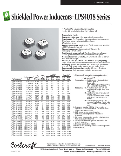
Core material FerriteCore and winding loss See /corelossTerminations RoHS compliant silver-palladium-platinum-glass frit.Other terminations available at additional cost.Weight 54 – 64 mgAmbient temperature –40°C to +85°C with I rms current, +85°C to +125°C with derated currentStorage temperature Component: –40°C to +125°C.Packaging: –40°C to +80°CResistance to soldering heat Max three 40 second reflows at +260°C, parts cooled to room temperature between cyclesMoisture Sensitivity Level (MSL)1 (unlimited floor life at <30°C /85% relative humidity)Failures in Time (FIT) / Mean Time Between Failures (MTBF)38 per billion hours / 26,315,789 hours, calculated per Telcordia SR-332Packaging 1000/7″ reel; 3500/13″ reel Plastic tape:12 mm wide,0.23 mm thick, 8 mm pocket spacing, 1.9 mm pocket depth Recommended pick and place nozzle OD: 4 mm;ID: ≤ 2 mm PCB washing Only pure water or alcohol recommended1.Please specify termination and packaging codes:LPS4018-223M LCTermination:L =RoHS compliant silver-palladium-platinum-glass frit.Special order:T = RoHS tin-silver-copper (95.5/4/0.5)or S = non-RoHS tin-lead (63/37).Packaging:C =7″ machine-ready reel. EIA-481embossed plastic tape (1000 parts per full reel).B =Less than full reel. In tape, but notmachine ready.To have a leader and trailer added ($25 charge), use code letter C instead.D =13″ machine-ready reel. EIA-481embossed plastic tape. Factory order only, not stocked (3500 parts per full reel).2.Inductance tested at 100 kHz, 0.1 Vrms using an Agilent/HP 4192A. Inductance at 1 MHz is the same for parts with SRF ≥10 MHz.3.DCR measured on a micro-ohmmeter.4.SRF measured using Agilent/HP 8753ES or equivalent.5.DC current that causes the specified inductance drop from its value without current.6.Current that causes the specified temperature rise from 25°C ambient.7.Electrical specifications at 25°C.Refer to Doc 362 “Soldering Surface Mount Components”before soldering.DCR SRFI sat (A)5I rms (A)6Inductance 2max 3typ 410%20%30%20°C 40°C Part number 1(µH)(Ohms)(MHz)drop drop drop rise rise LPS4018-561ML_0.56 ±20%0.033250 4.8 5.2 5.3 1.9 2.8LPS4018-102NL_ 1.0 ±30%0.042180 3.8 3.9 4.0 1.8 2.5LPS4018-222ML_ 2.2 ±20%0.07090 2.7 2.8 2.9 1.5 2.0LPS4018-332ML_ 3.3 ±20%0.08075 1.9 2.0 2.0 1.4 1.9LPS4018-472ML_ 4.7 ±20%0.12565 1.8 1.9 1.9 1.3 1.8LPS4018-682ML_ 6.8 ±20%0.15050 1.2 1.3 1.3 1.0 1.5LPS4018-103ML_10 ±20%0.20040 1.1 1.2 1.30.90 1.25LPS4018-153ML_15 ±20%0.260320.860.910.940.80 1.12LPS4018-183ML_18 ±20%0.270270.780.830.850.70 1.00LPS4018-223ML_22 ±20%0.360260.740.800.830.650.90LPS4018-333ML_33 ±20%0.420200.580.640.680.550.80LPS4018-473ML_47 ±20%0.650160.510.550.560.450.68LPS4018-683ML_68 ±20%0.950130.410.450.460.400.56LPS4018-104ML_100 ±20% 1.40100.340.360.370.350.50LPS4018-124ML_120 ±20% 1.609.00.310.330.340.300.45LPS4018-154ML_150 ±20% 2.008.00.270.290.300.280.40LPS4018-184ML_180 ±20% 2.507.50.240.260.270.260.36LPS4018-224ML_220 ±20% 3.70 6.50.210.2250.2350.200.30LPS4018-334ML_330 ±20% 5.90 5.50.180.190.200.170.23LPS4018-474ML_470 ±20%7.80 4.50.140.160.170.150.20LPS4018-564ML_560 ±20%10.0 4.00.130.140.150.140.18LPS4018-684ML_680 ±20%11.5 3.50.120.130.140.120.16LPS4018-824ML_820 ±20%14.0 2.90.110.120.130.100.14LPS4018-105ML_1000 ±20%18.0 2.80.100.110.110.0980.125LPS4018-155ML_1500 ±20%25.0 2.40.0950.100.1050.0800.110LPS4018-185ML_1800 ±20%31.5 2.30.0900.0950.1000.0700.095LPS4018-225ML_2200 ±20%32.5 2.10.0880.0940.1000.0700.090LPS4018-335ML_3300 ±20%48.01.60.0820.0920.0940.0550.075•Very low DCR; excellent current handling •4.0 × 4.0 mm footprint; less than 1.8 mm tall– LPS4018 SeriesTypical L vs CurrentFrequency (MHz)I n d u c t a n c e (µH )Current (A)I n d u c t a n c e (µH )P e r c e n t o f r a t e d c u r r e n tcontact Coilcraft or visit .。
