TRNSYS17培训资料
TRNSYS入门以及经验
TRNSYS入门以及经验01:TRNSYS包介绍15版本:trnshell:trnsys的主要运行环境,可以编辑trnsys独立运行程序(可以提供给非trnsys用户,资料的选择可以通过下拉菜单或者填上数字,并可以查看运行结果,处理数据,画图等)trnsed:读取trnshell创建的独立的运行程序simCAD:独立的软件,和trnsys配合使用,来建立建筑模型trnlib:用户添加自己的部件的编辑器IIsibat:trnsys的界面,由法国公司开发出提供给用户末端一个友好的界面Prebid:建筑编辑模块spreadsheet and chart:用来读取数据并处理与画图。
16版本:trnsys studio:trnsys的用户界面,15中为IIsibat,16中改名为此trnedit:编辑trnsys独立程序,trnsys的主要运行环境15里的trnshellTRNBuild 建筑编辑模块15里面的Prebid。
02:trnsys使用的方法目前我知道就3种方法,大家可以找出新的应用方法,在这里交流1:直接在trnsys里面运行,不利用trnsys simulation studio,不利用用户界面,可以建立dck文件,直接编辑,然后利用trnsys运行2:在trnsys simulation studio建立project,直接找出模块,连接,运行的时候自动生成dek文件,然后在trnsys里面运行3:在其他软件里边调用TRNSYS,如matlab,在matlab里面运行的时候,直接调用trnsys。
DLL文件。
03 添加自己的部件到trnsys由于前期的trnsys开发一直使用fortran来作为基础语言,在添加自己的部件的时候,不可避免的要用到fortran,本人推荐用CVF6.6B,因为trnsys自带的说明书和各种编写部件大部分会以它来作为基础语言。
两种方法:1:根据trnsys16的说明书的第2章和第8章的说明,一步步进行,最后生成部件的外部动态连接文件,比如type111.DLL,这样把这个文件直接发给其他用户,就可以直接调用,无须其他改动。
(完整版)Trnsys模块序列中英文对照表

(完整版)Trnsys模块序列中英文对照表Trnsys中英文对照1Application library (应用文库)1.1年度时间表1.1.1数据开始的日期在1月一日以后519b1.1.2数据开始的日期在1月一日519a1.2供暖制冷的每日设定点5141.3供暖制冷的季节时间表5151.4小时时间表1.4.1一周时间相同5171.4.2工作日,周末5161.5月份时间表5181.6供暖制冷的每周时间表5202Controllers (控制器)2.13级室内恒温器2.1.1热延迟8a2.1.2热延迟与温度死区8b2.25级室内恒温器1082.3不同控制器的磁滞2.3.1温度2.3.1.1求解器0(可代替)的控制策略2b2.3.1.2求解器1(鲍威尔)的控制策略2a2.3.2一般情况2.3.2.1求解器0(可代替)的控制策略2d2.3.2.2求解器1(鲍威尔)的控制策略2c2.4反馈迭代控制器222.5微处理控制器402.6比例积分控制器233Controllers library (控制器文库)3.15阶多区域恒温器6983.25阶房间恒温器6453.3水温自动调节仪3.3.1制冷模型5033.3.2供暖模型5023.4延时输入6613.5恒湿器6583.6N阶微分控制器3.6.1制冷模型6723.6.2供暖模型6713.7比例控制器6694Electric (电学)4.1电池4.1.1输入流4.1.1.1谢菲德方程47d4.1.1.2谢菲德方程改进后的海曼方程47e 4.1.2输入能量4.1.2.1dQ/dt=P eff 47a4.1.2.2谢菲德方程47b4.1.2.3谢菲德方程改进后的海曼方程47c 4.1.3增加气流效果1854.2燃料电池4.2.1AC燃料电池188a4.3柴油机4.3.1DEGS分配控制器102a4.3.2类属模型120a4.3.3特殊DEGS120b4.4光伏面板4.4.15参数模型1944.4.2晶硅电池模型94a4.4.3热电联供控制器4.4.3.1聚光型4.4.3.1.1不变损失4.4.3.1.1.1电池的工作电压作为输入50g4.4.3.1.1.2电池的工作电压没作为输入50e4.4.3.1.2顶部损失(以风速、环温为未知的函数)4.4.3.1.2.1电池的工作电压作为输入50h4.4.3.1.2.2电池的工作电压没作为输入50f4.4.3.2平板控制器4.4.3.2.1根据透过率的角关系50c4.4.3.2.2不变损耗50a4.4.3.2.3损失=f(T,WS,G)与t=f(角度)50d4.4.3.2.4损失=f(温度,风速,几何)50b4.4.4薄膜电池94b4.4.5带有数据文件的电池阵列4.4.5.1不跟踪最大功率点4.4.5.1.1热计算用MODE=1 180b4.4.5.1.2热计算用MODE=2 180d4.4.5.1.3热计算用MODE=3 180f4.4.5.2跟踪最大功率点4.4.5.2.1热计算用MODE=1 180a4.4.5.2.2热计算用MODE=2 180c4.4.5.2.3热计算用MODE=3 180e4.5电量调节4.5.1输入电量已知175a4.5.2输出电量已知175b4.6调节器与变频器4.6.1带有蓄电池的系统4.6.1.1阵列电压=电池电压48d4.6.1.2MPP追踪4.6.1.2.1SOC与SOV的监测48c4.6.1.2.2只检测SOC 48b4.6.2不带有蓄电池的系统48a4.7风力涡轮机5GHP Library(燃气热泵文库)5.1水平管道地埋5.1.1明细的5565.1.2简略的31b5.2地上热交换器5.2.1垂直套管5.2.1.1标准557d5.2.1.2热阻已知557c5.2.2垂直U形管5.2.2.1标准557a5.2.2.2热阻已知557b5.3地面温度模型5015.4水源热泵5.4.1含湿量504a5.4.2相对湿度504b6Green Building Library(绿色建筑文库) 6.1先进的灯管控制6.1.1自动调光7266.2建筑一体化6.2.1有玻璃的6.2.1.1简单建筑接口模型6.2.1.1.1光伏输入效率,ASHRAE,IAMs 566-1 6.2.1.1.2光伏输入效率,包括性能566-26.2.1.1.3文件读取光伏效率,ASHRAE,IAMs 566-3 6.2.1.1.4文件读取光伏效率,包括性能566-46.2.1.1.5光伏效率修改器,ASHRAE,IAMs566-5 6.2.1.1.6光伏效率修改器,包括性能566-66.2.1.2使用56型的接口6.2.1.2.1光伏输入效率,ASHRAE,IAMs 567-1 6.2.1.2.2光伏输入效率,包括性能567-26.2.1.2.3文件读取光伏效率,ASHRAE,IAM567-3s 6.2.1.2.4文件读取光伏效率,包括性能567-46.2.1.2.5光伏效率修改器,ASHRAE,IAMs567-5 6.2.1.2.6光伏效率修改器,包括性能567-66.2.2无玻璃的6.2.2.1简单建筑接口模型6.2.2.1.1光伏输入效率569-16.2.2.1.2文件读取光伏效率569-26.2.2.1.3光伏效率修改器569-36.2.2.2使用56型的接口6.2.2.2.1光伏输入效率568-16.2.2.2.2文件读取光伏效率568-26.2.2.2.3光伏效率修改器568-36.3灯光6.3.1连续阶梯7276.3.2多功率级7286.4光伏阵列遮蔽5516.5PVT集热器6.5.1复杂建筑系统的相互作用5636.5.2简单建筑系统的相互作用5606.6简单光伏模型6.6.1覆盖6.6.1.1恒定效率562a6.6.1.2光伏输入效率562b6.6.1.3文件读取光伏效率562c6.6.1.4光伏效率修改器562d6.6.2未覆盖6.6.2.1恒定效率562e6.6.2.2光伏输入效率562f6.6.2.3文件读取光伏效率562g6.6.2.4光伏效率修改器562h6.7窗6.7.1NFRC窗6877Ground Coupling Library(地面耦合文库) 7.1地下室热损失7.1.1使用56型的接口7.1.1.1输入输出文件701a7.1.1.2输入文件,无输出文件701b7.1.1.3无输入文件,无输出文件701d 7.1.1.4无输入文件,有输出文件701c 7.1.2区域空气接口7.1.2.1输入输出文件702a7.1.2.2输入文件,无输出文件702b7.1.2.3无输入文件,无输出文件702c 7.1.2.4无输入文件,有输出文件702d 7.1.3简单ASHRAE方法7157.2平板供暖及地板辐射7.2.1使用56型的接口7.2.1.1输入输出文件705a7.2.1.2输入文件,无输出文件705b 7.2.1.3无输入文件,无输出文件705d 7.2.1.4无输入文件,有输出文件705c 7.2.2区域空气接口7.2.2.1输入输出文件706a7.2.2.2输入文件,无输出文件706c 7.2.2.3无输入文件,无输出文件706d 7.2.2.4无输入文件,有输出文件706b 7.2.3简单的1节点模型6537.2.4没有土壤储存7.2.4.1使用56型的接口7127.2.4.2区域空气接口7137.3平板等级7.3.1使用56型的接口7.3.1.1输入输出文件703a7.3.1.2输入文件,无输出文件703b 7.3.1.3无输入文件,无输出文件703d 7.3.1.4无输入文件,有输出文件703c 7.3.2区域空气接口7.3.2.1输入输出文件704a7.3.2.2输入文件,无输出文件704b 7.3.2.3无输入文件,无输出文件704d 7.3.2.4无输入文件,有输出文件704c 7.3.3简化的ASHRAE方法7.3.3.1平板不绝热714c7.3.3.2平板部分绝热714a7.3.3.3平板绝热714b7.4地埋部件土壤模型7.4.1水平管7117.4.2垂直柱形储蓄槽7.4.2.1输入输出文件707a7.4.2.2输入文件,无输出文件707c7.4.2.3无输入文件,无输出文件707b7.4.2.4无输入文件,有输出文件707d 8Heat Exchangers(热交换器)8.1恒定效率换热器918.2逆流式5b8.3交叉流式8.3.1两种流体混合5f8.3.2两种流体不混合5e8.3.3冷端混合5c8.3.4热端混合5d8.4顺溜式5a8.5壳管式5g8.6废热回收179HVAC9.1吸收式制冷1079.2辅助冷却单元929.3辅助加热器69.4空调设备9.4.11个自变量42c9.4.22个自变量42b9.4.33个自变量42a9.5冷却盘管9.5.1详细9.5.1.1环形翅片52a9.5.1.2矩形翅片52b9.5.2简单模型329.6冷却塔9.6.1外部性能文件51a9.6.2用户定义系数51b9.7双源热泵209.8加热炉9.8.1输入含湿量121a9.8.2输入相对湿度121b 9.9并联冷水机组539.10部分负荷性能9.10.1线性负荷43b9.10.2外部文件性能43a10HVAC Library(HVAC文库) 10.1双管控制单元10.1.1能源率控制负载673 10.2吸收式制冷10.2.1双效蒸发器10.2.1.1直燃式67810.2.1.2热水燃烧式677 10.2.1.3蒸汽燃烧式676 10.2.2单效蒸发器10.2.2.1直燃式68110.2.2.2热水燃烧式680 10.2.2.3蒸汽燃烧式679 10.3空调10.3.1分离数据的形式10.3.1.1输入含湿量651-1 10.3.1.2输入相对湿度651-2 10.3.2统一数据的形式10.3.2.1输入含湿量756a 10.3.2.2输入相对湿度756b 10.4空调设备10.4.1绝对湿度模型696a10.4.2相对湿度模型696b10.5空气式热回收10.5.1空气换热器10.5.1.1显热和潜热10.5.1.1.1输入含湿量667a10.5.1.1.2输入相对湿度667b10.5.1.2只有显热10.5.1.2.1输入含湿量760a10.5.1.2.2输入相对湿度760b10.5.2能量转轮10.5.2.1输入含湿量667c10.5.2.2输入相对湿度667d10.5.3焓转轮10.5.3.1输入含湿量667c10.5.3.2输入相对湿度667d10.5.4热管10.5.4.1输入含湿量689a10.5.4.2输入相对湿度689b10.5.5热转轮10.5.5.1输入含湿量760c10.5.5.2输入相对湿度760a10.5.6吸湿热交换10.5.6.1输入含湿量667c10.5.6.2输入相对湿度667d10.5.7透过墙平板换热器10.5.7.1输入含湿量667a10.5.7.2输入相对湿度667b 10.6空气源热泵10.6.1电辅热10.6.1.1输入含湿量665-310.6.1.2输入相对湿度665-410.6.2气辅热10.6.2.1输入含湿量665-510.6.2.2输入相对湿度665-610.6.3无辅热10.6.3.1输入含湿量665-110.6.3.2输入相对湿度665-2 10.7空气热泵10.7.1电辅热10.7.1.1输入含湿量665-310.7.1.2输入相对湿度665-410.7.2气辅热10.7.2.1输入含湿量665-510.7.2.2输入相对湿度665-610.7.3无辅热10.7.3.1输入含湿量665-110.7.4输入相对湿度665-210.8辅助加热器(空气)10.8.1输入含湿量643-110.8.2输入相对湿度643-210.9辅助加热器(流体)65910.10锅炉10.10.1输入效率70010.10.2外部效率75110.11冷却装置10.11.1空气冷却器65510.11.2水冷却器66610.12闭路冷却塔51010.13冷却盘管10.13.1旁路部分方法10.13.1.1输入含湿量10.13.1.1.1独立盘管508h10.13.1.1.2出口空气湿度控制508g10.13.1.1.3出口空气温度控制508f10.13.1.1.4出口流体温度控制508e10.13.1.2输入相对湿度10.13.1.2.1独立盘管508a10.13.1.2.2出口空气湿度控制508d10.13.1.2.3出口空气温度控制508c10.13.1.2.4出口流体温度控制508b10.13.2性能图10.13.2.1输入含湿量697a10.13.2.2输入相对湿度697b10.13.3简单的制冷与除湿10.13.3.1输入含湿量10.13.3.1.1出口空气湿度控制752d10.13.3.1.2出口空气温度控制752a10.13.3.1.3温度与湿度控制10.13.3.1.3.1温度与含湿量752b10.13.3.1.3.2温度与相对湿度752c10.13.3.2输入相对湿度10.13.3.2.1出口空气湿度控制752d10.13.3.2.2出口空气温度控制752a10.13.3.2.3温度与湿度控制10.13.3.2.3.1温度与含湿量752g10.13.3.2.3.2温度与相对湿度752h 10.14除湿器10.14.1旋转干燥剂除湿器68310.14.2单一除湿器10.14.2.1输入含湿量688a10.14.2.2输入相对湿度688b10.15节热器10.15.1焓的控制10.15.1.1输入含湿量684a 10.15.1.2输入相对湿度684b 10.15.2湿度控制10.15.2.1输入含湿量684c 10.15.2.2输入相对湿度684d 10.15.3温度控制10.15.3.1输入含湿量684e 10.15.3.2输入相对湿度684f 10.16蒸发冷却器10.16.1直接蒸发冷却10.16.1.1输入含湿量506c 10.16.1.2输入相对湿度506d 10.16.2间接蒸发冷却10.16.2.1输入含湿量757a 10.16.2.2输入相对湿度757b 10.17液体冷却69210.18雾化装置10.18.1输入含湿量507a 10.18.2输入相对湿度507b 10.19锅炉10.19.1输入含湿量643-1 10.19.2输入相对湿度643-2 10.20地热热泵10.20.1输入含湿量505a 10.20.2输入相对湿度505b 10.21换热器10.21.1空气与空气10.21.1.1空气与空气换热10.21.1.1.1显热与潜热10.21.1.1.1.1输入含湿量667a10.21.1.1.1.2输入相对湿度667b10.21.1.1.2只有显热10.21.1.1.2.1输入含湿量760b10.21.1.1.2.2输入相对湿度760a10.21.1.2能量转轮10.21.1.2.1输入含湿量667c10.21.1.2.2输入相对湿度667d10.21.1.3焓转轮10.21.1.3.1输入含湿量667c10.21.1.3.2输入相对湿度667d10.21.1.4热管10.21.1.4.1输入含湿量689a10.21.1.4.2输入相对湿度689b10.21.1.5热转轮10.21.1.5.1输入含湿量760b10.21.1.5.2输入相对湿度760a10.21.1.6吸湿热交换10.21.1.6.1输入含湿量667c10.21.1.6.2输入相对湿度667d10.21.1.7透过墙平板除湿器10.21.1.7.1输入含湿量667a10.21.1.7.2输入相对湿度667b10.21.2流体与流体10.21.2.1冷面调整10.21.2.1.1使热面大于最小值66910.21.2.1.2使热面小于最小值65710.21.2.2热面调整10.21.2.2.1使冷面大于最小值65210.21.2.2.2使冷面小于最小值650 10.22供热与通风单元10.22.1无户外空气10.22.1.1输入含湿量663-310.22.1.2输入相对湿度663-410.22.2有户外空气10.22.2.1输入含湿量663-310.22.2.2输入相对湿度663-410.23加热盘管10.23.1旁通系数方法10.23.1.1输入含湿量10.23.1.1.1可自由活动的盘管753a 10.23.1.1.2出口空气温度控制753b 10.23.1.1.3出口流体温度控制753c 10.23.1.2出入相对湿度10.23.1.2.1可自由活动的盘管753d 10.23.1.2.2出口空气温度控制753e 10.23.1.2.3出口流体温度控制753f 10.23.2效率方法10.23.2.1输入含湿量67010.23.2.2输入相对湿度670-110.23.3简单供热与加湿10.23.3.1输入含湿量10.23.3.1.1出口空气含湿量控制754c 10.23.3.1.2出口空气控制754d 10.23.3.1.3温度与湿度控制10.23.3.1.3.1温度与含湿量754b 10.23.3.1.3.2温度与相对湿度754a 10.23.3.2输入相对湿度10.23.3.2.1出口空气含湿量控制754e 10.23.3.2.2出口空气控制754f10.23.3.2.3温度与湿度控制10.23.3.2.3.1温度与含湿量754g10.23.3.2.3.2温度与相对湿度754h 10.24加湿器10.24.1输入含湿量641-110.24.2输入相对湿度641-210.25末端暗装的热泵10.25.1电辅热10.25.1.1输入含湿量665-1510.25.1.2输入相对湿度665-1610.25.2气辅热10.25.2.1输入含湿量665-1710.25.2.2输入相对湿度665-1810.25.3无辅热10.25.3.1输入含湿量665-1310.25.3.2输入相对湿度665-1410.26分析式热泵系统10.26.1电辅热10.26.1.1输入含湿量665-910.26.1.2输入相对湿度665-1010.26.2气辅热10.26.2.1输入含湿量665-1110.26.2.2输入相对湿度665-1210.26.3无辅热10.26.3.1输入含湿量665-710.26.3.2输入相对湿度665-810.27湿垫冷却器10.27.1输入含湿量506c10.27.2输入相对湿度506d10.28暖风机10.28.1无户外空气10.28.1.1输入含湿量663-110.28.1.2输入相对湿度663-2 10.28.2有户外空气10.28.2.1输入含湿量664-1 10.28.2.2输入相对湿度664-2 10.29单一空调10.29.1分离的数据格式10.29.1.1输入含湿量651-1 10.29.1.2输入相对湿度651-2 10.29.2统一的数据格式10.29.2.1输入含湿量756a 10.29.2.2输入相对湿度756b 10.30水回路热泵10.30.1输入含湿量505a10.30.2输入相对湿度505b 10.31水源热泵10.31.1输入含湿量505a10.31.2输入相对湿度505b 10.32水热泵66811Hydrogen Systems(氢系统)11.1压缩气体储存罐11.1.1氢11.1.1.1理想气体164a11.1.1.2实际气体164b11.2压缩机16711.3控制器11.3.1电解槽11.3.1.1恒定功率模型100b 11.3.1.2变功率模型100a11.3.2主控制105a11.4电解器11.4.1高碱性11.4.1.1TMODE=1 160a11.4.1.2TMODE=2 160b11.4.1.3TMODE=3 160c11.5燃料电池11.5.1AFC11.5.1.1空气-氢气173a11.5.1.2氧气-氢气173b11.5.2质子交换膜燃料电池11.5.2.1空气-氢气11.5.2.1.1TMODE=111.5.2.1.1.1RTCTMODE=1 170a11.5.2.1.1.2RTCTMODE=2 170b11.5.2.1.1.3RTCTMODE=3 170c11.5.2.1.2TMODE=211.5.2.1.2.1RTCTMODE=1 170d11.5.2.1.2.2RTCTMODE=2 170e11.5.2.1.2.3RTCTMODE=3 170f11.5.2.2氧气-氢气11.5.2.2.1TMODE=111.5.2.2.1.1RTCTMODE=1 170g11.5.2.2.1.2RTCTMODE=2 170h11.5.2.2.1.3RTCTMODE=3 170i11.5.2.2.2TMODE=211.5.2.2.2.1RTCTMODE=1 170i11.5.2.2.2.2RTCTMODE=2 170k11.5.2.2.2.3RTCTMODE=3 170l 12Hydronics(循环系统)12.1风机12.1.1恒定转速12.1.1.1输入含湿量112a12.1.1.2无湿度3a12.1.1.3无湿度,无能耗系数3c12.1.1.4输入相对湿度112b12.1.2变转速12.1.2.1输入含湿量111a12.1.2.2输入相对湿度111b12.2分流器12.2.1湿空气11e12.2.2其他流体11f12.3混合器12.3.1湿空气11c12.3.2其他流体11d12.4风管3112.5减压阀1312.6水泵12.6.1恒定转速114/3b12.6.2恒定转速,无能耗系数3d12.6.3变转速11012.7三通12.7.1湿空气11g12.7.2其他流体11h12.8调温阀12.8.1湿空气11a12.8.2其他流体11b13Hydroncs Library(循环加热冷却文库) 13.1循环管70913.2风机13.2.1输入流速13.2.1.1输入含湿量744-113.2.1.2输入相对湿度744-213.2.2设定流速13.2.2.1恒定流速13.2.2.1.1输入含湿量642-113.2.2.1.2输入相对湿度642-213.2.2.2双速风机13.2.2.2.1输入含湿量644-113.2.2.2.2输入相对湿度644-213.2.2.3变速风机13.2.2.3.1输入含湿量662-113.2.2.3.2输入相对湿度662-213.3静压箱13.3.1回风静压箱13.3.1.1输入含湿量648-113.3.1.2输入相对湿度648-213.3.2送风静压箱13.3.2.1输入含湿量646-113.3.2.2输入相对湿度646-213.4泵13.4.1输入流速13.4.1.1变转速13.4.1.1.1效率降低,压降的功率74213.4.1.1.2多项式关系的功率74313.4.1.1.3泵特性曲线与系统特性曲线的匹配748 13.4.2输入功率13.4.2.1变转速13.4.2.1.1效率降低,压降的模型74513.4.2.1.2多项式功率系数74613.4.2.1.3泵特性曲线与系统特性曲线的匹配749 13.4.3设定流速13.4.3.1恒定转速13.4.3.1.1恒定功率65413.4.3.1.2效率降低,压降的功率74013.4.3.1.3泵特性曲线与系统特性曲线的匹配74713.4.3.2变转速13.4.3.2.1多项式关系的效率69513.4.3.2.2效率降低,压降的功率74113.4.3.2.3多项式关系的功率65613.4.3.2.4泵特性曲线与系统特性曲线的匹配750 13.5阀门13.5.1分流阀13.5.1.1空气13.5.1.1.1输入含湿量646-113.5.1.1.2输入相对湿度646-213.5.1.2其他流体64713.5.2混合阀13.5.2.1空气13.5.2.1.1输入含湿量648-113.5.2.1.2输入相对湿度648-213.5.2.2其他流体64914Loads and Structures(负荷与结构)14.1太阳房14.1.1附加热质量68a14.1.2无附加热质量37b14.2多区域建筑14.2.1有标准输出文件56a14.2.2无标准输出文件56b14.3伸出与悬挂遮阳3414.4单区域模型14.4.1复杂单区域1914.4.1.1附加输出14.4.1.1.1能率控制输出19-E14.4.1.1.2水平温度控制输出19-T 14.4.1.2几何模型14.4.1.2.1面积比方法几何014.4.1.2.2矩形六面体方法几何114.4.1.2.3用户定义因素几何214.4.1.3表面14.4.1.3.1墙14.4.1.3.1.1输入导热墙 condwall 14.4.1.3.1.2外墙14.4.1.3.1.2.1标准ASHRAE墙 Awall 14.4.1.3.1.2.2用户自定义Pwall14.4.1.3.1.3内分区14.4.1.3.1.3.1标准ASHRAE分区 Apart 14.4.1.3.1.3.2用户自定义Ppart14.4.1.3.1.4屋顶14.4.1.3.1.4.1标准ASHRAE屋顶 Aroof 14.4.1.3.1.4.2用户自定义Proof14.4.1.3.1.5隔墙14.4.1.3.1.5.1标准ASHRAE隔墙 Azsep 14.4.1.3.1.5.2用户自定义Pzsep14.4.1.3.2窗14.4.1.3.2.1输入透射比 19wind-2 14.4.1.3.2.2内部计算透射比 19wind-1 14.4.1.4区域14.4.1.4.1能率控制 ERzone14.4.1.4.2水平温度控制TLzone14.4.2能量空间的符合14.4.2.1能率控制14.4.2.1.1供热与制冷 12b14.4.2.1.2只供热12a14.4.2.2水平温度控制12c14.4.3集总电容建筑8814.5蓄热墙14.5.1输入流速,内部计算透射比36c 14.5.2内部计算流速,输入透射比36b 14.5.3输入流速,透射比36a14.5.4内部计算流速,透射比36d14.6窗14.6.1测量数据35a14.6.2理论值35b15Loads and Structures TESS(负荷与结构) 15.1能率负荷转化69015.2出流管负荷15.2.1空气69315.2.2其他流体68215.3简单建筑15.3.1无内部控制15.3.1.1输入含湿量759a15.3.1.2输入相对湿度759b15.3.2有内部控制15.3.2.1输入含湿量660a15.3.2.2输入相对湿度660b15.4综合建筑68615.5窗15.5.1NFRC窗68716Obsolete (废弃部件)16.1空气吸收式制冷机16.1.1能率控制7b16.1.2水平温度控制7a16.2外部调用DLL 6116.3加速收敛器4416.4CSTB气候数据 9f16.5绘图2616.6滤波辐射处理器16.6.1已知发射和扩散16f16.6.2已知水平16b16.6.3已知水平温度和湿度16d16.6.4已知horiz,direct normal 16h16.6.5已知horiz,horiz diffuse 16i 17Optimization Library(优化文库) TRNORT 18Output(输出)18.1经济性分析18.1.1详细分析29b18.1.2P1,P2方法29a18.2直方图绘制18.2.1时间间隔18.2.1.1导出外部文件27a18.2.1.2导出列表文件27b18.2.2数值间隔18.2.2.1导出外部文件结果27c18.2.2.2导出列表文件27d18.3网络绘图18.3.1带有文件的网络绘图18.3.1.1无单位65c18.3.1.2带有trnsys提供的单位65a18.3.1.3用户自定义单位65b18.3.2无文件的网络绘图65d18.4打印18.4.1格式化18.4.1.1无单位25f18.4.1.2带有trnsys提供的单位25d18.4.1.3用户自定义单位25e18.4.2未格式化18.4.2.1EES查询表25h18.4.2.2无单位25c18.4.2.3带有trnsys提供的单位25a 18.4.2.4用户自定义单位25b18.5模拟概要18.5.1外部文件结果18.5.1.1带有能量平衡28a18.5.1.2不带有能量平衡28b18.5.2列表文件结果18.5.2.1带有能量平衡28c18.5.2.2不带有能量平衡28d19Physical Phenomena(物理现象) 19.1集热器阵列遮挡19.1.1平板阵列30a19.1.2抛物槽集热器阵列19.1.2.1轴线在内表面19.1.2.1.1垂直轴线30d/30b19.1.2.1.2水平轴线30c19.2对流系数计算19.2.1水平表面19.2.1.1默认系数80a19.2.1.2用户自定义系数80b19.2.2垂直表面19.2.2.1默认系数80c19.2.2.2用户自定义系数80d19.3辐射处理器19.3.1发送率和扩散率已知16e 19.3.2已知总辐射16a19.3.3已知总辐射,湿度16c19.3.4已知总辐射,直辐16g19.3.5已知总辐射,水平发散率16i19.4遮阳罩19.4.1开放遮挡6819.4.2开放和水平遮挡6719.4.3单一遮挡罩6419.5简单的地面温度模型7719.6天空温度19.6.1计算云量69b19.6.2写入云量69a19.7热力学性能19.7.1焓湿图(干球温度度,露点温度,湿球温度,相对湿度,含湿量和焓)19.7.1.1已知干球和露点温度33d19.7.1.2已知干球和焓33b19.7.1.3已知干球和含湿量33c19.7.1.4已知干球和相对湿度33e19.7.1.5已知干球和湿球33f19.7.1.6已知含湿量和焓33a19.7.2制冷剂与蒸汽性能5819.8气候生成器19.8.1默认随机数19.8.1.1无外部文件54c/54a19.8.2自定义随机数19.8.2.1无外部文件54d/54b20Solar Library(太阳文库)20.1空气热集热器56120.2真空管集热器53820.3平板集热器20.3.1电容效果20.3.1.1平均温度模型540 20.3.1.2进口温度模型539 20.3.2蛇管集热器65620.3.3理论塔板管集热器20.3.3.1理论最大损失654b 20.3.3.2用户定义最大损失654a 20.3.4无覆盖的集热器20.3.4.1理论计算55920.3.4.2输入用户定义效率553 20.3.5出口温度控制53720.4闷晒式20.4.1平板模型20.4.1.1带有HX20.4.1.1.1盘管20.4.1.1.1.1双轴向IAM541d 20.4.1.1.1.2理论IAM541i 20.4.1.1.2水平管20.4.1.1.2.1双轴向IAM541b 20.4.1.1.2.2理论IAM541g 20.4.1.1.3蛇管20.4.1.1.3.1双轴向IAM541e 20.4.1.1.3.2理论IAM541i 20.4.1.1.4垂直管20.4.1.1.4.1双轴向IAM541c 20.4.1.1.4.2理论IAM541h 20.4.1.2不带有HX20.4.1.2.1双轴向IAM541a 20.4.1.2.2理论IAM541f20.4.2管状ICS模型20.4.2.1单轴线IAM 550IAM MODE420.4.2.2其他第一轴线IAM 550IAM MODE2 20.4.2.3双轴线IAM 550IAM MODE720.4.2.4其他第二轴线IAM 550IAM MODE3 20.4.2.5IAM乘法模型方法IAM 550IAM MODE6 20.4.2.6无IAM 550IAM MODE120.4.2.7理论IAM 550IAM MODE520.5抛物线集线器53620.6最大损失统计20.6.1双层玻璃54420.6.2单层玻璃54321Solar Thermal Collector(太阳能集热器)21.1复合抛物面集热器7421.2真空管集热器7121.3绘制集热器性能图21.3.1二次入射角修正72b21.3.2双轴入射角修改器72e21.3.3覆盖及吸收性能72d21.3.4入射角修正值=f72c21.3.5无入射角修正72a21.4二次效率集热器21.4.1二次入射角修正1b21.4.2双轴入射角修改器1e21.4.3覆盖及吸收性能1d21.4.4入射角修正值=f1c21.4.5无入射角修正1a21.5理论平板集热器7321.6带有蓄热系统的虹吸集热器。
trnsys复习与总结
瞬态系统模拟计算机程序a TRaNsient SYstem Simulation program总结与复习Summarize and Review1. 常见部件..............................................................................................................................- 1 -1.1数据读取部件................................................................................................................- 1 -1.1.1气象数据读取.....................................................................................................- 1 -1.1.2一般数据读取.....................................................................................................- 2 -1.2 控制系统..................................................................................................................- 2 -1.3积分................................................................................................................................- 3 -1.4输出................................................................................................................................- 3 -1.5 计算器...........................................................................................................................- 3 -1.6 动力系统.......................................................................................................................- 3 -1.7 时刻表...........................................................................................................................- 3 -1.8 外部连接部件...............................................................................................................- 4 -1.8.1 excel....................................................................................................................- 4 -1.8.2 EES.....................................................................................................................- 5 -1.8.3 matlab..................................................................................................................- 5 -1.8.4 comis/fluent/contam............................................................................................- 5 -2. 常见问题集锦......................................................................................................................- 5 -2.1编程问题........................................................................................................................- 6 -2.1.1 编写部件............................................................................................................- 6 -2.1.1.1 创建部件.................................................................................................- 6 -2.1.1.2 写源代码.................................................................................................- 6 -2.1.1.3 创建部件的DLL文件.............................................................................- 6 -2.1.1.4 重新编译TRNSYS的DLL文件..............................................................- 7 -2.2部件使用......................................................................................................................- 11 -2.3功能实现......................................................................................................................- 11 -2.3.1模拟时间步长和精度的选择...........................................................................- 11 -2.3.2 计算器..............................................................................................................- 12 -2.3.3 TRNSYS功能...................................................................................................- 13 -2.4 常用数据.....................................................................................................................- 14 -2.4.1一年中月份的小时数和天数...........................................................................- 14 -2.4.2 角度修正IAM..................................................................................................- 14 -2.5......................................................................................................................................- 15 -1.常见部件一般的模拟过程中,大部分用户都要用到的部件,常见的有资料读取部件、输出部件、控制部件、积分部件、计算器等等。
trnsys手册部分翻译

瞬态系统模拟计算机程序a TRaNsient SYstem Simulationprogram说明书使用指南:本书仅对trnsys 16入门学习做初步指导,并没有提供关于TRNSYS模拟软件和实用程序的详细介绍。
详细介绍在会以后章节中一一列出。
注册过的用户可在TRNSYS上下载最新的版本。
修正记录:• 2004-09 TRNSYS 16.00.0000• 2005-02 TRNSYS 16.00.0037• 2009-11 TRNSYS 17.00.0000如何获取更多的信息:关于程序和程序应用的详细资料,用户可以在TRNSYS或是太阳能实验室的TRNSYS联系人那里获取。
绪论绪论针对TRNSYS本身及其套件做了简单介绍。
从中您可以学会如何安装、打开例子、在模拟演示窗口创建系统以及如何使用多维建筑界面。
(TRNBuild)TRNSYS简单介绍TRNSYS是一个完整的、仿真环境具有可扩展性的瞬态仿真系统,包括多区的建筑物。
来自世界各地的工程师和研究人员借此验证新能源的概念,从简单的家庭热水系统的设计到模拟建筑物及其设备,包括控制策略、居住者的行为,、替代能源系统(如风能,太阳能,光伏发电,氢能系统)等。
在过去的25年里,TRNSYS成功的一个关键因素在于系统的开放及其模块化结构。
末端用户可以获取软件的源代码核,以及部件模型。
这有助于简化现有的大模式,以使其更适应用户的特殊需要。
基于DLL核的结构化设计,用户或第三开发商可以使用一些常见的编程语言(C, C + + ,PASCAL, FORTRAN, 等等),便可轻松地添加用户设定的部件。
此外, TRNSYS可以很容易地连接到许多其它应用软件,比如模拟的前处理或是后处理以及模拟过程过through interactive calls(例如Microsoft Excel, Matlab, COMIS ,等等)。
TRNSYS应用包括:•太阳能系统(集热和光伏)•低能耗建筑和新型空调系统(自然通风,平板加热/冷却,double façade,等等•可再生能源系统•热电联产,燃料电池•任何动态仿真系统TRNSYS术语:通常在模拟演示窗口中以图形的方式组建TRNSYSY模拟方案。
TRNSYS17培训资料
子系统
各种模块
标准TRNSYS软件中有13个大组库,每个组库中有若干个模块,可被用户任意调用。 13个大组库分别为:
Controllers Electrical Components Heat Exchangers HVAC Hydrogen Systems Hydronics Building Loads and Structures Output Devices Physical Phenomena Solar Collectors Thermal Storage Utility Subroutines Weather Data Reading and Processing
准确性
冷辐射末端
准确性
地源热泵系统1
美国田纳西州-住宅 系统能耗
建筑负荷
地源热泵系统2
准确性
地源热泵系统3
地源热泵系统4
项目实测与模拟计算 (美国)
项目实测与模拟计算 (香港)
中国建筑科学研究院
准确性
常用计算地源热泵系统的软件
不同软件与TRNSYS比对
各软件的调整
(由IEA等中立机构完成)
-
外窗辐射负 荷
30.124
-
总负荷 44.956
43.2
外墙负荷 -8.45
-
屋面负荷 -6.55
-
热负荷
外窗传热负 荷
-27.66
-
外窗辐射负 荷
2.73
-
总负荷
-39.09
-42
DeST -
45.73 -
-41.22
eQUEST TRNSYS
6.183
-
5.127
-
-
-
(完整版)trnsys总结

一模块解析1控制卡中模拟时间的选择start----stop一般情况下,模拟只能是开始时间小于结束时间一年中不同的月份以及其对应的小时数和天数月份天数小时数1 1 02 32 7443 60 14164 91 21605 121 28806 152 36247 182 43448 213 50889 244 583210 274 655211 305 729612 335 80161 366 87602 equation tool 的应用和简介功能:简单的计算:如output1=2*input2+sin(10*input3)+input1**3/20逻辑运算:output=GT(input1,input2)可以替代type2来当作控制器来控制机器的开关output=MOD(time,24)判断一年的总时间在一天中的时间主要用于:1.作为控制器来控制开关2.简单的负荷计算,作为时间的函数3.后处理工具,作为计算器来出来方程式,如集热器的效率计算,太阳能保证率,系统保证率等计算。
4.控制设备运行时刻表,这个功能比较差一点,建议用type14替代这个功能。
5.建筑里面控制方位角。
逻辑函数简介:1.ABS() 取绝对值2.ACOS() 反余弦函数3.AND( , ) 逻辑并4.ASIN() 反正弦函数5.ATAN() 反正切函数6.COS() 余弦函数7.EQL( a,b ) 如果a等于b,返回1,否则返回08.EXP() e 的次方,自然对数9.GT( a,b )如果a 大于b ,返回1,否则返回0 10.INT() 取整数 11.OR( , ) 逻辑或 12.LN() line 13.LOG() log1014.LT( a,b )如果a 小于b ,返回1,否则返回0 15.MAX( , ) 取最大 16.MIN( , ) 取最小 17.MOD( , ) 取余数 18.NOT() 逻辑非 19.SIN() 正弦函数 20.TAN() 正切函数 21.CONST 常数 22.TIME() 模拟的时间 23.START() 开始时间 24.STOP() 结束时间 25.STEP() 时间步长26.LE(a , b) 如果a 小于或者等于b ,返回1,否则返回0 27.NE(a ,b ) 如果a 不等于b ,返回1,否则返回0 28.AE( , )29.GE(a , b) 如果a 大于等于b ,返回1,否则返回03温差控制器太阳能-土壤源热泵系统模拟程序的运行除了要按照模型结构准确定义模拟参数和输入输出关系以外,还需要加入合理的控制模块。
Trnsys软件介绍和线上培训申请表
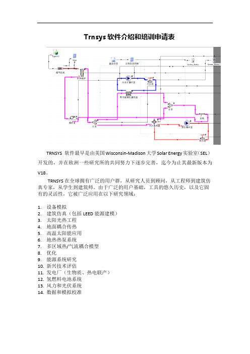
Trnsys软件介绍和培训申请表
TRNSYS 软件最早是由美国Wisconsin-Madison大学Solar Energy实验室(SEL)开发的,并在欧洲一些研究所的共同努力下逐步完善,迄今为止其最新版本为V18。
TRNSYS在全球拥有广泛的用户群,从研究人员到顾问,从工程师到建筑仿真专家,从学生到建筑师。
由于广泛的用户基础,工具的悠久历史,以及它固有的灵活性,它被广泛应用在以下研究领域:
1.设备模拟
2.建筑仿真(包括LEED能源建模)
3.太阳光热工程
4.地面耦合传热
5.高温太阳能应用
6.地热热泵系统
7.多区域热/气流耦合模型
8.优化
9.能源系统研究
10.新兴技术评估
11.发电厂(生物质、热电联产)
12.氢燃料电池系统
13.风力和光伏系统
14.数据和模拟校准
线上培训申请回执表。
01-GettingStarted
TRNSYS 16a T R a N s i e n t S Y s t e m S i m u l a t i o n p r o g r a mV o l u m e1G e t t i n g S t a r t e d/trnsyshttp://software.cstb.frTESS – Thermal Energy Systems SpecialistsTRNSYS 16 – Getting Started1–2About This ManualThe information presented in this manual is intended to provide a simple guide to get you started using TRNSYS 16. This manual is not intended to provide detailed reference information about the TRNSYS simulation software and its utility programs. More details can be found in other parts of the TRNSYS documentation set. The latest version of this manual is always available for registered users on the TRNSYS website (see here below).Revision history• 2004-09 For TRNSYS 16.00.0000 • 2005-02For TRNSYS 16.00.0037Where to find more informationFurther information about the program and its availability can be obtained from the TRNSYS website or from the TRNSYS coordinator at the Solar Energy Lab: TRNSYS CoordinatorSolar Energy Laboratory, University of Wisconsin-Madison 1500 Engineering Drive, 1303 Engineering Research Building Madison, WI 53706 – U.S.A.Email: trnsys@ Phone: +1 (608) 263 1586 Fax: +1 (608) 262 8464TRNSYS website: /trnsysNoticeThis report was prepared as an account of work partially sponsored by the United States Government. Neither the United States or the United States Department of Energy, nor any of their employees, nor any of their contractors, subcontractors, or employees, including but not limited to the University of Wisconsin Solar Energy Laboratory, makes any warranty, expressed or implied, or assumes any liability or responsibility for the accuracy, completeness or usefulness of any information, apparatus, product or process disclosed, or represents that its use would not infringe privately owned rights.© 2004 by the Solar Energy Laboratory, University of Wisconsin-MadisonThe software described in this document is furnished under a license agreement. This manual and the software may be used or copied only under the terms of the license agreement. Except as permitted by any such license, no part of this manual may be copied or reproduced in any form or by any means without prior written consent from the Solar Energy Laboratory, University of Wisconsin-Madison.TRNSYS 16 – Getting Started TRNSYS ContributorsS.A. Klein W.A. Beckman J.W. MitchellJ.A. Duffie N.A. Duffie T.L. FreemanJ.C. Mitchell J.E. Braun B.L. EvansJ.P. Kummer R.E. Urban A. FikselJ.W. Thornton N.J. Blair P.M. WilliamsD.E. Bradley T.P. McDowell M. Kummert Additional contributors who developed components that have been included in the Standard Library are listed in Volume 5.Contributors to the building model (Type 56) and its interface (TRNBuild) are listed in Volume 6. Contributors to the TRNSYS Simulation Studio are listed in Volume 2.1–3TRNSYS 16 – Getting Started 1–4TRNSYS 16 – Getting StartedT ABLE OF CONTENTS1.G ETTING S TARTED1–7 1.1.What is TRNSYS? 1–7 1.2.The TRNSYS Suite 1–9 1.2.1.The TRNSYS Simulation Studio 1–9 1.2.2.The TRNSYS Simulation engine 1–10 1.2.3.The Building visual interface 1–11 1.2.4.TRNEdit and TRNSED applications 1–11 1.2.5.TRNSYS add-ons 1–12 1.3.Installation 1–13 1.3.1.System requirements 1–13 1.3.2.Installing TRNSYS 16 1–14 1.3.3.Installing the expanded weather data 1–15 ing TRNSYS examples 1–17 1.4.1.Opening and running a simple example 1–17 1.4.2.Opening and running an example with the Multizone building model (Type 56) 1–24 1.5.Creating a TRNSYS project 1–29 1.5.1.System description 1–29 1.5.2.Modeling approach 1–30 1.5.3.Step-by-Step instructions to create the Project 1–31 1.6.Creating a building project 1–39 ing the Building wizard 1–39 1.6.2.Modifying the wizard-generated project 1–45 1.ing TRNEdit and creating a redistributable (TRNSED) application 1–49 1.7.1.Starting point: TRNSYS Studio project 1–49 1.7.2.Editing the TRNSED file in TRNEdit 1–51 1.7.3.Some refinements 1–54 1.7.4.Adding pictures, links and multiple tabs 1–57 1.7.5.Creating the redistributable application 1–59 1.8.Running TRNSYS 15 projects 1–61 1.8.1.Introduction 1–61 1.8.2.The TRNSYS 15 "Begin" example 1–62 1.8.3.The TRNSYS 15 "Building" example 1–66 1.9.Creating a new component 1–73 1.9.1.Create the component proforma 1–73 1.9.2.Generating a Fortran code skeleton and a compiler project 1–74 ing other compilers or creating Types in other programming languages 1–791–5TRNSYS 16 – Getting Started1.10.More TRNSYS Examples 1–80 1–6TRNSYS 16 – Getting Started 1. G ETTING S TARTEDThe getting started manual explains what TRNSYS is and what programs make the TRNSYS suite. You will learn how to install TRNSYS, how to open and run the examples, how to create a project in the Simulation Studio and how to use the Multizone Building interface (TRNBuild). 1.1. What is TRNSYS?TRNSYS is a complete and extensible simulation environment for the transient simulation of systems, including multi-zone buildings. It is used by engineers and researchers around the world to validate new energy concepts, from simple domestic hot water systems to the design and simulation of buildings and their equipment, including control strategies, occupant behavior, alternative energy systems (wind, solar, photovoltaic, hydrogen systems), etc.One of the key factors in TRNSYS’ success over the last 25 years is its open, modular structure. The source code of the kernel as well as the component models is delivered to the end users. This simplifies extending existing models to make them fit the user’s specific needs.The DLL-based architecture allows users and third-party developers to easily add custom component models, using all common programming languages (C, C++, PASCAL, FORTRAN, etc.). In addition, TRNSYS can be easily connected to many other applications, for pre- or post-processing or through interactive calls during the simulation (e.g. Microsoft Excel, Matlab, COMIS, etc.). TRNSYS applications include:•Solar systems (solar thermal and PV)•Low energy buildings and HVAC systems with advanced design features (natural ventilation, slab heating/cooling, double façade, etc.)•Renewable energy systems•Cogeneration, fuel cells•Anything that requires dynamic simulation!Some TRNSYS jargon:A TRNSYS project is typically setup by connecting components graphically in theSimulation Studio. Each Type of component is described by a mathematicalmodel in the TRNSYS simulation engine and has a set of matching Proforma'sin the Simulation Studio The proforma has a black-box description of acomponent: inputs, outputs, parameters, etc.TRNSYS components are often referred to as Types (e.g. Type 1 is the solarcollector). The Multizone building model is known as Type 56.The Simulation Studio generates a text input file for the TRNSYS simulationengine. That input file is referred to as the deck file.In this manual, %TRNSYS16% refers to the TRNSYS 16 installation directory,i.e. C:\Program Files\Trnsys16 if you chose to keep the default location1–7TRNSYS 16 – Getting Started 1–8TRNSYS 16 – Getting Started1–91.2. The TRNSYS SuiteTRNSYS consists of a suite of programs: The TRNSYS simulation Studio, the simulation engine (TRNDll.dll) and its executable (TRNExe.exe), the Building input data visual interface (TRNBuild.exe), and the Editor used to create stand-alone redistributable programs known as TRNSED applications (TRNEdit.exe).1.2.1. The TRNSYS Simulation StudioThe main visual interface is the TRNSYS Simulation Studio (formerly known as IISiBat). From there, you can create projects by drag-and-dropping components to the workspace, connecting them together and setting the global simulation parameters.The Simulation Studio creates the TRNSYS saves the project information in a Trnsys Project File (*.tpf). When you run a simulation, the Studio also creates a TRNSYS input file (text file thatcontains all the information on the simulation but no graphical information).Figure 1–1: The TRNSYS Simulation StudioThe simulation Studio also includes an output manager from where you control which variables are integrated, printed and/or plotted, and a log/error manager that allows you to study in detail what happened during a simulation.TRNSYS 16 – Getting Started1–10You can also perform many additional tasks from the Simulation Studio: Generate projects using the "New Project Wizard", generate a skeleton for new components using the Fortran Wizard, view and edit the components proformas (a proforma is the input/output/parameters description of a component), view output files, etc.1.2.2. The TRNSYS Simulation engineThe simulation engine is programmed in Fortran and the source is distributed (see the \SourceCode directory). The engine is compiled into a Windows Dynamic Link Library (DLL), TRNDll. The TRNSYS kernel reads all the information on the simulation (which components are used and how they are connected) in the TRNSYS input file, known as the deck file (*.dck). It also opens additional input files (e.g. weather data) and creates output files.The simulation engine is called by an executable program, TRNExe, which also implements the online plotter, a very useful tool that allows you to view dozens of output variables during asimulation.Figure 1–2: The online plotter in TRNExeThe online plotter provides some advanced features such as zooming and display of numerical values of the variables at any time step, as shown in the zoom part of Figure 1–2.1.2.3. The Building visual interfaceTRNBuild (formerly known as Prebid) is the tool used to enter input data for multizone buildings. It allows you to specify all the building structure details, as well as everything that is needed to simulate the thermal behavior of the building, such as windows optical properties, heating and cooling schedules, etc.Figure 1–3: TRNBuildTRNBuild creates a building description file (*.bui) that includes all the information required to simulate the building. Note that this was not the case in TRNSYS 15 where the window library (w4-lib.dat) was always required to run a simulation.1.2.4. TRNEdit and TRNSED applicationsTRNEdit is an specialized editor that can be used to create or modify TRNSYS input files (decks). This is not recommended in general and only advanced users should attempt to modify deck files by hand. Most users should rely on the Simulation Studio to generate and modify deck files.On the other hand, TRNEdit can be used to create redistributable applications (known as TRNSED applications). Those executables can be freely distributed to end-users who do not have a TRNSYS license in order to offer them a simplified simulation tool. The distributable includes a dedicated visual interface designed by adding special commands to the TRNSYS inputfile. Advanced features, such as multiple windows (tabs) and clickable pictures, have been added in TRNSYS 16.Figure 1–4: TRNEdit – Tabbed view to design TRNSED applicationsFor more information on TRNSED applications licensing, please check the license.txt file in your installation.1.2.5. TRNSYS add-onsTRNSYS offers a broad variety of standard components, and many additional libraries are available to expand its capabilities:• TRNLIB: /trnsys/trnlib (free component library)•TRANSSOLAR libraries: •TESS libraries: 1.3. Installation1.3.1. System requirements1.3.1.1. SoftwareO PERATING SYSTEMTRNSYS requires Windows 95/98, NT 4.0, 2000, ME or Windows XP. Windows 2000 or XP are recommended due to known issues in resource management in previous Windows versions (those issues are not relate to TRNSYS nor its utility programs).C OMPILERSThanks to the drop-in DLL technology, no compiler is required to add components to TRNSYS if you obtain them as a precompiled DLL.If you wish to debug TRNSYS or to add components for which you received the Fortran code, you will need a Fortran compiler (Please see the Programmer's Guide for supported compilers). If you wish to create your own components, you will need a compiler capable of creating a DLL. This includes any recent Windows-compatible compiler for C++, Delphi, Fortran or other languages.O THERViewing the documentation requires the free Acrobat reader (Version 6.0 or higher is recommended to benefit from advanced searching capabilities).1.3.1.2. HardwareTRNSYS requirements will mostly depend on the simulations you want to run. The specifications here below list the basic requirements and the recommended configuration. The latter should allow you to run yearly simulations with a 0.1 sec time step using the full capabilities of the online plotter, while the basic configuration will allow you to run more typical simulations.M INIMUM CONFIGURATION•Pentium III processor or equivalent•128 MB of RAM•200 MB of available disk space (up to 2 GB if you install all the optional weather data files)R ECOMMENDED CONFIGURATION•Pentium IV processor 2.0 GHz or equivalent•512 MB of RAM• 1 GB of available disk space (up to 3 GB if you install all the optional weather data files)1.3.2. Installing TRNSYS 16Run the Setup program (trnsys16-setup-16-xx-xxxx.exe). where xx.xxxx is the exact release number. The Setup program will guide you through a series of dialog boxes with simple options. You will be prompted to accept the license agreement to continue the installation.Figure 1–5: Installing TRNSYS 16 - Part 1 You can navigate between the dialog boxes using the Back and Next Buttons. You will go through a few basic options.Figure 1–6: Installing TRNSYS 16 - Part 2 You will be asked to choose a default set of libraries for building data (materials and glazing). If you have many TRNSYS 15 projects that you need to update, choose the libraries that you were using in TRNSYS 15. If your country is listed, use those libraries (they were created by local distributors and are often in languages other than English). If you do not know what to do, keep the default choice (Basic). Note that you can always change the default libraries later in TRNBuild. You will then be asked if you want to create shortcuts and associate file extensions with TRNSYS. You should select that option unless you have already installed TRNSYS 16 and you have customized your shortcuts or associations.When you have selected a few options such as the destination directory, Setup will ask your confirmation to start the installation.Figure 1–7: Installing TRNSYS 16 – Part 3When the installation is complete, the Setup program will attempt to copy your user registration data (the "user16.id" file) to the destination folder. If you install from a CD provided by your distributor, Setup should be able to locate the file. If it is not the case (e.g. if you are installing a downloaded version), you should copy the "user16.id" file provided by you distributor according to the message displayed on the last screen of the Setup program.When you click "Finish", Setup will exit and launch your default browser to display the release notes of the version you have just installed. You can skip this by unchecking the "Display Release Notes" checkbox on the last screen of the Setup program (this is not recommended as the Release Notes have important information on the program you have just installed).1.3.3. Installing the expanded weather dataAfter installing TRNSYS 16, the setup program will try to copy your user registration data to the destination directory. The registration information is contained in a small text file, user16.id. If you install from a CD obtained from your distributor, Setup should find the user16.id file and install it. If you downloaded TRNSYS from the web, Setup will inform you in case it can't find the user16.id file. In that case you just need to copy that file to the installation directory (C:\Program Files\Trnsys16 by default). Please contact your distributor if you cannot locate your registration information.The TRNSYS Setup installs a few weather data files that will show you an example of the available data sources and data formats. However, TRNSYS 16 comes with a comprehensive set of weather data files including more than 1000 locations in more than 140 countries. Please refer to Volume 6 of the documentation (Weather Data) for more information on the available data sources and locations.If you wish to proceed with the installation of the expanded weather data base, just run the weather data Setup program, trnsys16-weather-16-xx-xxxx.exe (where xx-xxxx is the release number). The Setup program is very similar to the TRNSYS 16 installation program and will lead you through a few steps with dialog boxes.Figure 1–8: Installing the expanded weather data You can choose which datasets to install or not (the available packages may not match the screenshot here below depending on your version). Please note that installing all the data files will require more than 1.5 GB of available disk space on your computer.When the weather data installation is completed, you are ready to use TRNSYS.1.4. Using TRNSYS examplesThis section explains how you can quickly get started using TRNSYS by opening and running the examples provided with the distribution. You can then start creating your own projects by making changes to those examples.1.4.1. Opening and running a simple exampleLaunch the simulation Studio by using the created shortcut or by browsing to %TRNSYS16%\Studio\Exe and launching the Program called TrnsysStudio.exeGo to File/Open and select %TRNSYS16%\Examples\Begin\Begin.tpf. A TRNSYS project consists of components (e.g. a solar collector, a data reader, a printer) linked together.Figure 1–9: The "Begin" example1.4.1.1. Component configurationYou can check a component's configuration by double-clicking its icon. This will open a window with multiple tabs. When you open the window, the foremost tab shows a list of parameters and their value (the solar collector parameters are shown in Figure 1–9). You can see additional information about the parameters by clicking the "More" button.You can explore the different tabs to view the component's inputs, outputs and derivatives (if any – derivatives are capacitive variables of the component, e.g. nodes representing a given amount of water in a storage tank).Note: The values and units displayed in the input tab give the initial values for thecorresponding inputs. They are overridden during the simulation if those inputsare connected to other components1.4.1.2. ConnectionsIf you double-click on a link between two components, you will open a new window that lists all input-output connections inside that link. Figure 1–10 shows the link between Type 109 (weather data reading and processing) and Type 1b (solar collector)Figure 1–10: Example of connection windowIf there are many available inputs and outputs, the lists will be longer than what can be displayed. You can resize the window and/or use the scrollbars.Note: The Simulation Studio can be set to auto-scroll in the connection window(as well as in the project window). If you want to enable/disable that mode, go toFile/Settings/Project and check/uncheck the "auto-scroll" boxes.it may be easier to make new connections after aligning a given output with the input to which it is connected. To do this, click on the bottommost icon on the left (see Figure 1–11 for an example).Figure 1–11: Aligned connection windowYou can also decide to show only the inputs and outputs that have given dimensions. Figure 1–12 shows the results when "angle" is selected. Note that inputs/outputs with "any" or "unknown" dimensions will always be displayed.Figure 1–12: Filtered connection windowAlternatively, you can use the table view to display and manage connections: Just switch from the "Classic" tab to the "Table" tab. The result is shown in Figure 1–13.Figure 1–13: Aligned connection window1.4.1.3. Running the simulation and viewing the resultsYou can run a simulation by pressing the "F8" key, which is the shortcut for "Calculate/Run Simulation".T HE ONLINE PLOTTERIf at least one "online plotter" component is present in the simulation, an online plot will be displayed during the simulation. The online plotter offers several features that will help you analyze the simulation results while it is running and after it is done.You can interrupt / resume the simulation while it is running by right-clicking anywhere in the plot, by using the "F7" and "F8" keys, or using the "Calculation/Stop" and "Calculation/Resume" menu entries. The "Pause at…" command is also very useful when you want to diagnose some problems occurring at a given time in a simulation.When the simulation is stopped, you can use the "Plot options" menu to change the plot background or line thickness. You can also change the left and right Y-axis limits by clicking on the axes themselves, which will display a dialog box (see Figure 1–14). Please note that changes to those limits will be lost if you re-run the simulation. You should change the online plotter parameters in the simulation itself (double-click on the online plotter icon) if you want changes tobe permanent.Figure 1–14: Online plotter in a paused simulation with Y-axis control boxYou can hide or show any variable in the plot by clicking on its name in the legend fields. For example clicking in the red circle in Figure 1–14 would hide/show the QAux plot.A NALYZING THE SIMULATION: ZOOMING AND DISPLAYING NUMERICAL VALUESYou can zoom on part of the plot to have a more detailed view of a shorter time interval. Just click on the upper-left corner of the area you want to zoom in and drag the mouse pointer to the lower-right corner, then release the mouse button. In the zoom window, you can adjust the Y-axis limits but also the X-axis (time) limits by clicking on the axes. This is very useful when you want to study such a short period of time that it is hard to zoom on that period right away.You can display the numerical value of any variable at any point in time in both the "normal" and the "zoom" windows. Press the SHIFT key and mover the mouse over the graph. The variable labels will be replaced with their value (and "time" will be replaced with the simulation time). Thisis shown in Figure 1–15 for the zoom window.Figure 1–15: Online Plotter: Displaying numerical valuesNote: By pressing SHIFT and moving the mouse over the plot, you will displaythe values plotted by the online plotter, which are interpolated between TRNSYStime steps. If you want to see only the actual simulation time steps, pres CTRL-SHIFT when moving the mouse. This can be useful to study control signalswitching from 0 to 1, for example, since the online plotter will draw a continuousline between those 2 states and it will show interpolated values that do notcorrespond to any simulated values.C LOSING THE ONLINE PLOTTER AND ANALYZING PRINTED RESULTSAt the end of the simulation, you will be asked if you wish to exit the online plotter. If you click "No", you will be able to use the online plotter commands described here above. If you click "Yes", you will come back to the Simulation Studio, from where you can view the printed results.You can open external files (input or output files) by using the "Calculate/Open/External Files" menu or by double-clicking on the component that uses a file, switching to the "External Files" tab and using the "Edit" button (Figure 1–16). Both actions will open the file using the editor set in "File/Settings/Directories/Text Editor" (Notepad by default).Note: In a file name, "***" means that TRNSYS will use the input file (.dck)filename to assign a name at the file at runtime. Example: if your project's inputfile is called "MyProject.dck" and you type in "***.dat" as the output file name,TRNSYS will create a file called "MyProject.dat".Warning: the input (deck) file name is not always the same as the TRNSYSStudio project's name. The deck filename is set in the project's Control Cards,which can be accessed by "Assembly/Control Cards" or by the appropriatetoolbar buttonFigure 1–16: Opening external filesThe Standard TRNSYS components always create text files, but you can use any file extension in a project. In particular, some users find it convenient to use the file extension registered with their preferred spreadsheet program, e.g. ".xls" for Microsoft Excel. This allows opening those files in the spreadsheet program by double-clicking their name in Windows Explorer. Please note, however, that the created files only have plain text information. Special features, like colors, cannot be created with the standard components.T ROUBLESHOOTING A SIMULATION (THE E RROR M ANAGER)During a simulation, TRNSYS writes messages to a special file called the Log file. That file has the same name as the input file (deck) with a ".log" extension. Another file, the Listing file, is also created (the listing file also has all messages but in addition it repeats the input file and has some additional printed outputs like the results of a "Trace" command, which prints the inputs and outputs of a component at each iteration).The Simulation Studio provides access to the Log and Listing file through the Error Manager, which can be accessed by clicking on the LST button. Figure 1–17 shows an example of error message when an equation refers to a non-existent variable. The TRNSYS simulation ends with a "TRNSYS Errors" dialog box. You can then return to the Simulation Studio by clicking OK, and you can launch the Error Manager to analyze notices, warnings and error messages that weregenerated during the simulation.Figure 1–17: The Error ManagerThe "Units stats" and "Types stats" of the Error Manager present additional information on the calculation time spent in each component and on the number of times each component was called. Finally, clicking on the "Lst File" tab will open the listing file in a text editor.1.4.2. Opening and running an example with theMultizone building model (Type 56)The "Sunspace" example is a simple example inspired by BESTEST Case 960. BESTEST (Building Energy Simulation programs TEST) is the methodology developed in the framework of the IEA to test and diagnose the simulation capabilities of the exterior envelope portions ofbuilding energy simulation programs.1.4.2.1. Opening and running the exampleIn the simulation Studio, open %TRNSYS16\Examples\SunSpace\SunSpace.tpf. You can explore the connections and the components configuration as explained here above.Figure 1–18: The SunSpace exampleWhen you run the example (F8), TRNSYS launches TRNBuild in order to process the building input data. This ensures that the data used in TRNSYS matches the latest version of the .bui file and that Type 56 will find all intermediate files it uses for the simulation (.bld, .trn and .inf). After the automatic call to TRNBuild, the online plotter is displayed and the simulation runs.。
trnsys手册部分翻译
瞬态系统模拟计算机程序a TRaNsient SYstem Simulation program说明书使用指南:本书仅对trnsys 16入门学习做初步指导,并没有提供关于TRNSYS模拟软件和实用程序的详细介绍。
详细介绍在会以后章节中一一列出。
注册过的用户可在TRNSYS网站上下载最新的版本。
修正记录:•2004-09 TRNSYS 16.00.0000•2005-02 TRNSYS 16.00.0037•2009-11 TRNSYS 17.00.0000如何获取更多的信息:关于程序和程序应用的详细资料,用户可以在TRNSYS网站或是太阳能实验室的TRNSYS绪论绪论针对TRNSYS本身及其套件做了简单介绍。
从中您可以学会如何安装、打开例子、在模拟演示窗口创建系统以及如何使用多维建筑界面。
(TRNBuild)TRNSYS简单介绍TRNSYS是一个完整的、仿真环境具有可扩展性的瞬态仿真系统,包括多区的建筑物。
来自世界各地的工程师和研究人员借此验证新能源的概念,从简单的家庭热水系统的设计到模拟建筑物及其设备,包括控制策略、居住者的行为,、替代能源系统(如风能,太阳能,光伏发电,氢能系统)等。
在过去的25年里,TRNSYS成功的一个关键因素在于系统的开放及其模块化结构。
末端用户可以获取软件的源代码内核,以及部件模型。
这有助于简化现有的大模式,以使其更适应用户的特殊需要。
基于DLL内核的结构化设计,用户或第三开发商可以使用一些常见的编程语言(C, C + + ,PASCAL, FORTRAN, 等等),便可轻松地添加用户设定的部件。
此外,TRNSYS可以很容易地连接到许多其它应用软件,比如模拟的前处理或是后处理以及模拟过程中通过through interactive calls(例如Microsoft Excel,Matlab,COMIS ,等等)。
TRNSYS应用包括:•太阳能系统(集热和光伏)•低能耗建筑和新型空调系统(自然通风,平板加热/冷却,double façade,等等•可再生能源系统•热电联产,燃料电池•任何动态仿真系统TRNSYS术语:通常在模拟演示窗口中以图形的方式组建TRNSYSY模拟方案。
Trnsys中文教程-第一册

Trnsys中⽂教程-第⼀册TRNSYS 18 A TraN sient Sy stem S imulation program第1卷Volume 1⼊门Getting Started⽬录。
TABLE OF CONTENTS1.开始1–5。
1. GETTING STARTED 1–51.1.本⼿册是什么?1—5。
1.1. What is this manual? 1–51.2.什么是trnsys?1—5。
1.2. What is TRNSYS? 1–51.3.Trnsys是如何⼯作的?1—5。
1.3. How does TRNSYS work? 1–51.4.组件模型如何⼯作?1—6。
1.4. How do the component models work? 1–61.5.trnsys包中有哪些不同的程序?1—6。
1.5. What are the various programs in the TRNSYS package? 1–61.6.如何将组件模型添加到trnsys?1—8。
1.6. How are component models added to TRNSYS? 1–81.7.TRNSYS⽂档集中包括哪些不同的⼿册?1—8。
1.7. What are the different manuals included in the TRNSYS documentation set? 1–81.⼊门。
GETTING STARTED1.1. 这本⼿册是什么? What is this manual?《⼊门⼿册》的⽬的是解释trnsys如何⼯作以及组成trnsys包的不同⼯具背后的⼀些基本概念。
⼀旦你对这些基本概念有了了解,你就可以移动到⽂档集的其他卷上,这些⽂档集提供了关于使⽤TrnSyS的不同⼯具和教程的详细信息。
但在继续学习教程之前,理解本⼿册中包含的概念⾮常重要。
The intent of the Getting Started manual is to explain some of the basics concepts behind how TRNSYS works and the different tools that make up the TRNSYS package. Once you have an understanding of these basic concepts you can move to the other volumes of the documentation set that provide detailed information on the different tools and tutorials on the use of TRNSYS. But it is very important to understand the concepts included in this manual before proceeding with tutorials.1.2. 什么是trnsys? What is TRNSYS?trnsys是⼀个完整的、可扩展的系统暂态仿真环境,包括多区域建筑。
trnsys手册部分翻译

瞬态系统模拟计算机程序a TRaNsient SYstem Simulationprogram说明书使用指南:本书仅对trnsys 16入门学习做初步指导,并没有提供关于TRNSYS模拟软件和实用程序的详细介绍。
详细介绍在会以后章节中一一列出。
注册过的用户可在TRNSYS上下载最新的版本。
修正记录:• 2004-09 TRNSYS 16.00.0000• 2005-02 TRNSYS 16.00.0037• 2009-11 TRNSYS 17.00.0000如何获取更多的信息:关于程序和程序应用的详细资料,用户可以在TRNSYS或是太阳能实验室的TRNSYS联系人那里获取。
绪论绪论针对TRNSYS本身及其套件做了简单介绍。
从中您可以学会如何安装、打开例子、在模拟演示窗口创建系统以及如何使用多维建筑界面。
(TRNBuild)TRNSYS简单介绍TRNSYS是一个完整的、仿真环境具有可扩展性的瞬态仿真系统,包括多区的建筑物。
来自世界各地的工程师和研究人员借此验证新能源的概念,从简单的家庭热水系统的设计到模拟建筑物及其设备,包括控制策略、居住者的行为,、替代能源系统(如风能,太阳能,光伏发电,氢能系统)等。
在过去的25年里,TRNSYS成功的一个关键因素在于系统的开放及其模块化结构。
末端用户可以获取软件的源代码核,以及部件模型。
这有助于简化现有的大模式,以使其更适应用户的特殊需要。
基于DLL核的结构化设计,用户或第三开发商可以使用一些常见的编程语言(C, C + + ,PASCAL, FORTRAN, 等等),便可轻松地添加用户设定的部件。
此外, TRNSYS可以很容易地连接到许多其它应用软件,比如模拟的前处理或是后处理以及模拟过程过through interactive calls(例如Microsoft Excel, Matlab, COMIS ,等等)。
TRNSYS应用包括:•太阳能系统(集热和光伏)•低能耗建筑和新型空调系统(自然通风,平板加热/冷却,double façade,等等•可再生能源系统•热电联产,燃料电池•任何动态仿真系统TRNSYS术语:通常在模拟演示窗口中以图形的方式组建TRNSYSY模拟方案。
trnsys总结

下面的各行是在相应的体积流量下的泵所能提供的水头和泵的总效率
水头的单位是m
泵的总效率=水泵的效率×电机效率
即
图7
电机效率为图中Input的第4个参数
5变频水泵
如下图所示,变频泵的工作点是由系统的性能曲线和泵的性能曲线的交点确定的
泵的性能曲线为不同转速下的性能曲线,其实这个曲线是一个区域,即变频泵的工作区域。
3如果所需流量有部分小流量时,那就要在开始设置,0%转速和0流量的情况,这样水泵在运行时会自动通过差值计算小流量参数,从而不会超过外部文件中的最小值(外部文件已经是0,不会比这个更小了)。
6热泵
地源热泵两个换热器多为壳管式换热器,即地源热泵为水系统形式的热泵,在trnsys中选择type668水水热泵。
2Type749输入功率
3Type750输入转速
Type748是根据需要的出口流量来确定其他参数的,下面以type748为例
如下图一所示,这个需要的出口流量指的是Input中的3Desired outlet flow rate,这个值在Input中就是说,这个值是根据自己的需要变化的,可以自己定义的,即可以通过外部文件的方式输入,也可以通过模拟系统中的其他参数利用计算器计算出来。
图5
如图5所示,对于系统的性能曲线,type748是通过在parameter中定义实现的
定义的参数从8到11,所定义的公式如下
TRNSYS17新增功能
TRNSYS17新增功能(what's new)一、操作功能(1)增加了模块的重点突出功能(2)增加了模块的旋转功能(3)增加了计算器中公式的可视化功能二、新增了三维可视化建筑功能三、新增了空气分层、对流功能四、在线打印输出可以分屏显示五、New Components一、操作功能(1)增加了模块的重点突出功能随着计算模拟需求的增加,人们在Simulation Studio 软件中搭建的计算平台越来越复杂,对于某个模块,可能要与其他许多模块建立连接,这样,连线看起来错综复杂,难以辩解。
TRNSYS17增加了对模块重点突出的功能,即可以单独显示某个模块的所有连接线,如图1、图2所示。
图1-1 如何操作单独显示Type2b的连接图1-2 单独显示Type2b的连接(2)增加了模块的旋转功能对于某些模块,如管道、水泵等,随着水流,有进出方向。
TRNSYS17增加了模块的旋转功能,可以使模块的图标更加形象化,如图1-3所示。
图1-3 模块旋转(3)增加了计算器中公式的可视化功能对于计算器中的众多公式,可以以文本的形式显示出来。
图1-4 公式的可视化二、新增了三维可视化建筑功能对于TRNSYS17,通过软件TRNSYS3d和Goggle SketchUp TM实现了三维可视化建筑功能。
图1-5图1-6三、新增了空气分层、对流功能对于TRNSYS17,针对每个区,增加了空气分层功能,即可以考虑空气的竖向分区,如图1-7所示。
图1-7四、在线打印输出可以分屏显示对于在进行模拟计算时,比较重要的变量,可以通过TYPE65模块在线分屏显示,如图1-8所示。
图1-8五、 New Components在标准TRNSYS软件中,增加了一些新的模块,如:●∙∙Type 46 Printegrator●∙∙Differential equation solver●∙∙Type 49 Multizone slab model●∙∙Scope●∙∙Type 75 Sherman-Grimsrud Infiltration model●∙∙Type 15 weather data reader●∙∙Type 125 TRNSYS3d printer例如,增加了Type 49 Multizone slab model模块后,再通过后处理软件GroundDisplay_Slideshow.exe 可以实现图1-9所示的后处理情况。
(完整版)trnsys总结

一模块解析1控制卡中模拟时间的选择start----stop般情况下,模拟只能是开始时间小于结束时间一年中不同的月份以及其对应的小时数和天数月份天数小时数110232744360141649121605121288061523624718243448213508892445832102746552113057296123358016136687602 equati on tool的应用和简介功能:简单的计算:如output1=2*input2+sin (10*input3 ) +input1**3/20逻辑运算:output=GT ( inputl ,input2 )可以替代type2来当作控制器来控制机器的开关output=MOD (time,24)判断一年的总时间在一天中的时间主要用于:1•作为控制器来控制开关2. 简单的负荷计算,作为时间的函数3. 后处理工具,作为计算器来出来方程式,如集热器的效率计算,太阳能保证率, 系统保证率等计算。
4. 控制设备运行时刻表,这个功能比较差一点,建议用type14替代这个功能。
5. 建筑里面控制方位角。
逻辑函数简介:1. ABS()取绝对值2. ACOS0反余弦函数3. AND(,) 逻辑并4. ASIN()反正弦函数5. ATAN()反正切函数6. COS()余弦函数7. EQL( a,b ) 如果a等于b,返回1,否则返回0的次方,自然对数 如果a 大于b ,返回1,否则返回0 取整数 逻辑或 13. LOG() log1014. LT( a,b ) 如果a 小于b ,返回1,否则返回0 15.MAX( , ) 取最大 16. MIN( , ) 取最小17. MOD( , ) 取余数 18. NOT() 逻辑非 19.SIN() 正弦函数 20. TAN() 正切函数 21. CONST 常数 22. TIME() 模拟的时间 23.START() 开始时间 24.STOP() 结束时间 25.STEP() 时间步长 26. LE(a , b) 如果a 小于或者等于b ,返回1,否则返回0 27. NE(a ,b ) 如果a 不等于b ,返回1,否则返回0 28. AE( , ) 29. GE(a , b) 如果a 大于等于b ,返回1,否则返回03 温差控制器太阳能- 土壤源热泵系统模拟程序的运行除了要按照模型结构准确定义模拟 参数和输入输出关系以外, 还需要加入合理的控制模块。
- 1、下载文档前请自行甄别文档内容的完整性,平台不提供额外的编辑、内容补充、找答案等附加服务。
- 2、"仅部分预览"的文档,不可在线预览部分如存在完整性等问题,可反馈申请退款(可完整预览的文档不适用该条件!)。
- 3、如文档侵犯您的权益,请联系客服反馈,我们会尽快为您处理(人工客服工作时间:9:00-18:30)。
准确性
常用计算地源热泵系统的软件
夏季工况:
TRNSYS和
Energyplus
与实测相差7%
以内;
冬季工况
TRNSYS与实测
2006年不同软件与TRNSYS以及实验比对
差距也在11% 以内。
由Oklahoma State University(俄克拉荷马大学)2006年完成
试验验证 PCM-相变蓄热
国内外应用案例
一、能耗模拟概述
一、能耗模拟软件概述
与能耗模拟相关的术语 权威的能耗模拟软件 TRNSYS 作用与应用领域 TRNSYS 计算的准确性
能耗模拟的概念
负荷与能耗的区别 得热量与冷负荷 部分负荷工况与设计负荷工况
开环控制与闭环控制
权威的能耗模拟软件
IES BLAST
作用与应用领域
1
¾ 形成终端用户程序,为非TRNSYS用户提供方便; ¾ 输出结果可在线输出100多个系统变量,可形成EXCEL
计算文件; ¾ 与EnergyPlus、MATLAB等其它软件用:调用模块,搭建模拟平台; 用户可以
添加或者修改模块;形成各种动态仿真程序
TRNBuild
作用:输入建筑模型,与Google Sketchup结合;可输入三维建筑模型
TRNEdit
作用:形成终端用户程序,方便用户使用
TRNOPT
作用:进行最优化模拟计算
TRNBuild
Trnsys Studio TRNEdit
TRNOPT
指导思想
大系统 合成
子系统
子系统
子系统
相变蓄热TRNSYS模型
试验验证 PCM
相变蓄热理论计算与实测比对
二、TRNSYS软件简介
TRNSYS软件开发机构
TRNSYS(Transient System Simulation )软件是瞬时系统模拟程序, 最早由美国Wisconsin-Madison大学Solar Energy 实验室(SEL)开发,并在欧洲一 些研究所(CSTB、TRANSSOLAR )的共同研究 下逐步完善的。
各种模块
应用领域
建筑物全年的逐时能耗分析(三维建筑模型) 优化空调系统方案,预测系统运行费用 太阳能(太阳光热和光伏)系统模拟计算
地源热泵空调系统模拟计算 地板辐射供暖、供冷系统模拟计算
蓄热系统模拟计算 冷热电联产系统模拟计算 燃料电池、风力发电等模拟计算
软件的优势-开放性
z 源代码开放; z Drop-in 技术支持快捷式的新模块的开发与生成; z 与众多软件都有接口;(MATLAB, COMIS,CONTAM
环境效益分析 运行费用预测 节能效益分析
能耗模拟计算平台的搭建
计算的准确性
理论验证
验
证 方
程序间的对比验证
法
试验验证
理论对比验证
国内验证-软件及算例
算例1
算例2
国内验证-比对结果
算例1
算例2
软件 eQUEST TRNSYS
外墙负荷 2.573
-
屋面负荷 3.599
-
冷负荷
外窗传热负 荷
8.66
地埋管换热器进出口温度变化图
无辅助热源时,地埋管换热器进出口温度及土壤温度
变化图 其它实例-计算结果
有 变太 化阳 图能辅助时,其地它埋实管例换-热计器算进结出果口温度及土壤温度
案例介绍-地源热泵与太阳能复合式热泵
地源热泵设计工况下的供热量占设计负荷值的65.25%,但 在整个供暖季,热泵的供热量占总供热量的90%以上。
-12.364
-
-6.946
--
-
-
-19.311
-17.9
DeST -
9.03 -
-17.61
国外验证方法
ASHRAE 140-2007中第5章第2节
围
护
结
构
方
面
轻质围护结构下的全年耗热量
国外验证方法
ASHRAE 140-2007中第5章第2节
围 护 结 构 方 面
轻质围护结构下的全年耗冷量
国外验证方法
墙体数据库
¾具有单层、双层、多层、Low-e等多种不同窗户
¾遮阳的设置
窗户数据库
固定的水平、竖直遮阳装置 根据光照强度可移动式的遮阳装置
¾ 充分考虑冷风渗透、通风换气、室内发热源等 对建筑物逐时能耗的影响。
¾ 用户根据需要,任意添加不同建筑类别的空调设备运行时间表; 采暖和空调房间的温、湿度表;室内人员的逐时在室率表;灯 光、发热设备的开关时间表等。
46906
广联达信息大厦
第一个 LEED金 奖
ALF(美国)
第一个获得 innovation credit
2008美国10 大绿色建筑
案例介绍-能效测评
建筑负荷以及系统优化
中石油大厦
案例介绍-标准制定
外墙和玻璃优化
最优化决策 最优化围护结构
外墙数据库
建筑围护结构建模
窗户数据库
案例介绍-地源热泵
建筑围护结构建模 模拟优化使各单项围护结构节能技术在建筑中得以高效集成,也是能耗计算的基础
能耗模拟优化流程图
建筑能耗动态 模拟计算
配置空调采暖 系统和设备, 建立系统模拟。
调整改善围护 结构性能参数, 优化建筑体形、
窗墙比等。
对比基准建筑 和节能目标
根据结果和目 标,优化系统
配置
能源系统的全年 动态能耗计算
各种模块
除标准模块外,美国的热能研究中心TESS还开发出专门针对暖通空调系统的TESS Component Libraries 17.0。所以,该软件还特别适合于对能源系统进行优化分析与仿真 计算。TESS Component Libraries 17.0 由14个大组库构成:
Application Library Controller Library Electrical Library Geothermal Heat Pump Library Ground Coupling Library HVAC Equipment Library Hydronics Library Loads and Structures Library Optimization Library Solar Collector Library Storage Tank Library Utility Library Cogeneration (CHP) Library (新增) High Temperature Solar Library (新增)
案例介绍-绿色建筑
案例介绍-绿色建筑
丰田常熟(三星)
天津鼎润(两星)
南昌满庭春(三星) 第七届世界草莓大会培训中心(三星)
案例介绍-绿色建筑
万通天津新新家园零能耗会所
★★★ 绿色建筑创新奖
案例介绍-LEED
1 太阳能光伏发电 25637
2 风力发电方案
22619
3 发电量合计
48256
4
全年能耗
GENOPT,WINDOW5 ,Google Sketch) z 能进行建筑三维建模 (支持gbXML格式); z 可以调用其它能耗模拟软件的逐时负荷计算结果 ; z 可以识别任何格式的气象数据 ; z 简易的二次开发。
软件的优势-自建模块
用户自主开发的模块
软件的优势-自建平台
建筑负荷计算 太阳能热水
TRNSYS软件介绍
中国建筑科学研究院 建筑环境与节能研究院
冯晓梅 李骥等
联系方式
• 冯晓梅 010-84275107-803; fxmstar@
• 杜国付 010-84275107-802; fuguodu@
主讲内容
能耗模拟概述 TRNSYS软件简介 TRNSYS软件操作 中国建筑科学研究院在TRNSYS方面的应用和开发
示意图
冷却水系统
冷冻水系统
风系统
排风热回收系统
制冷机
机组性能曲线的输入-不同的蒸发温度、冷凝温度 机组的制冷量及耗电量的变化曲线
机组部分负荷性能曲线的输入 控制策略
变频水泵
水泵性能曲线的输入
输入风机的性能曲线
变频风机
控制策略
在线输出
释热量
逐时冷负荷 制冷系数
四、中国建筑科学研究院在TRNSYS 方面的应用和开发
系统优化
复合式 地源热 泵系统
软件的优势-自建平台
冷热电三联供
冷热电三联供 风力发电
软件的优势-专业性
z 系统优化; z 控制系统; z 太阳能方面; z 地源热泵方面(g-function); z 辐射计算方面; z 电力系统; z 复合式系统。
三、TRNSYS软件操作
TRNBuild软件
墙体构造层数据库
另外,美国的Thermal Energy Systems Specialists (TESS)专门开发出针对暖通空调系统的各种模块。
TRNSYS软件代理机构
TRNSYS软件的特点
¾ 模块的源代码开放,用户根据各自的需要修改或编写 新的模块并添加到程序库中;
¾ 计算灵活,模块化开放式结构,用户可以根据需要任 意建立连接,形成不同系统的计算程序;
-
外窗辐射负 荷
30.124
-
总负荷 44.956
43.2
外墙负荷 -8.45
-
屋面负荷 -6.55
-
热负荷
外窗传热负 荷
-27.66
-
外窗辐射负 荷
2.73
-
总负荷
-39.09
-42
DeST -
45.73 -
-41.22
eQUEST TRNSYS
6.183
