薄膜开关按键3.7X3.7X0.35 平脚贴片规格书
新款贴片压敏规格书(宁波勤创科技)
combinations to provide overvoltage, surge and lightning stroke protection for ACLED.
工作电压环境
前级压敏参数 后级压敏参数
Working Voltage Last-level
Next-level
备注
Environment
项目 Item
技术要求 Technical Requirement
测试条件及试验方法 Testing Condition and Method
无明显气泡、针孔等缺陷;无任
何降低使用性的可见性损伤;标
志清晰耐久。
4-1 外观
目测
4-1Appearance No obvious bubble, pinhole and
Pressure
Pressure
Remarks
Sensitive
Sensitive
110VAC±20%
Parameter 270VDC±10%
220-230VAC±20% 510VDC±10%
240VAC±20%
560VDC±10%
Parameter 470VDC±10% 510VDC±10%
两级压敏可提升至4KV防雷,用户根据对防浪 涌等级需求选用压敏体积大小配合。 Tow levels of pressure sensitive combinations can be improved to 4KV lightning protection; user can select pressure sensitive volume as needed. 印度、巴西国家推荐该组合 The combination is recommended for users in Indian and Brazil.
薄膜开关参数

薄膜开关参数一、薄膜开关的概述薄膜开关是一种具有紧凑结构、轻便易用的电子开关。
它主要由面板、薄膜、电路层和背板组成。
面板和背板通常由塑料或金属材料制成,而薄膜则承担了开关的导电和信号传输功能。
薄膜开关广泛应用于各种电子设备中,如手机、电脑、家电等。
二、薄膜开关的参数分类1.物理参数1) 尺寸规格:薄膜开关的尺寸可根据实际需求进行定制,以满足不同设备的应用场景。
2) 厚度:薄膜开关的厚度直接影响到其耐用性和稳定性。
一般来说,厚度越厚,耐用性越好。
3) 材质:薄膜开关的材质主要包括塑料、金属和复合材料等。
不同材质具有不同的性能,如耐磨性、抗冲击性等。
2.电气参数1) 电压:薄膜开关的电压参数决定了其适用的设备范围。
用户应根据设备电压选择合适的开关电压。
2) 电流:薄膜开关的电流参数表示其在工作时能承受的电流大小。
电流越大,承载能力越强。
3) 电阻:薄膜开关的电阻反映了其导电性能。
电阻越小,导电性能越好。
3.功能参数1) 按键数量:薄膜开关的按键数量可根据设备需求进行选择,如单一按键、多键组合等。
2) 开关形式:薄膜开关有多种形式,如常开、常闭、双向开关等。
用户应根据设备需求选择合适的开关形式。
3) 触发方式:薄膜开关的触发方式包括手动触发和自动触发。
手动触发适用于需要人为操作的场景,自动触发则适用于智能化设备。
三、各参数的具体解析1.物理参数1) 尺寸规格:根据设备空间大小和美观要求,选择合适的尺寸。
2) 厚度:在保证性能的前提下,尽量选择较薄的薄膜开关,以减轻设备重量。
3) 材质:根据设备使用环境和性能要求,选择具有相应性能的材质。
2.电气参数1) 电压:根据设备电压,选择合适的开关电压,以确保设备正常工作。
2) 电流:根据设备电流需求,选择能承受相应电流的薄膜开关。
3) 电阻:在保证导电性能的前提下,选择电阻较小的薄膜开关。
3.功能参数1) 按键数量:根据设备需求,选择合适的按键数量。
2) 开关形式:根据设备工作原理和需求,选择合适的开关形式。
薄膜面板开关按键技术资料

薄膜面板开关按键技术资料薄膜开关、薄膜面板是近年来国际流行的一种集装饰性与功能性为一体的电子整机产品的新的操纵系统,已成为我国电子产品升级换代、出口产品不可缺少的配套部件。
薄膜开关、面板集开关按键、面板功能文字、标记、商标、透明窗及显示于一体,并且采用多层整体密封结构。
因此它具有耐磨擦、防水、防尘、防有害气体、寿命长、性能稳定等特点。
为了整机的整洁,面板可以擦洗,字符不受损伤,色彩丰富、保新性好,安装方便。
不仅如此,薄膜开关、面板的应用,更能充分体现产品功能与色彩独具匠心的构思,以提高产品的外观质量和增加产品的时代气息。
薄膜开关、面板已广泛用于智能化电子测量仪器、医疗仪器计算机控制、数控机床、电子衡器、邮电通讯、复印机、电冰箱、微波炉、电风扇、洗衣机、电子游戏机等各类工业及家用电器产品。
薄膜开关薄膜面板薄膜面板薄膜面板是一种由弹性薄膜(PVC/PC/PET)加工而成的具有一定功能字符指示的装饰性面板,具有防水、防尘、耐摩擦、不褪色等优良特点,目前广泛用于家用电器、通讯设备、仪器仪表、工业控制等领域。
薄膜面板的印刷工艺要分为正面和反面印刷,分别应用于不同材质和类型的薄膜面板上。
大致可以分为平面类和压鼓类。
平面类薄膜面板是最简单的面板类型,主要是用不同颜色的文字、线条、色块对各个功能部位加以指示或加以区分,用户可以根据自身的需要来选择不同的薄膜材料及双面胶。
压鼓类薄膜面板是在平面型薄膜面板的基础上新开发出的一种较为美观而且实用的面板。
它的制作流程是,是在普通面板的基础上,通过一种压制模具,将面板经过热压后使按键部位微微凸起形成立体按键。
这种立体键不仅能准确地给定键体的范围,提高辨认速度,使操作者的触觉比较敏感,同时还增进了产品外观的装饰效果。
制作面板的薄膜应当具备哪些条件?面板薄膜是将彩色油墨丝印至透明高分子聚合物背面,一旦丝印完成并切割成形,此层就成为彩色面膜层。
面膜层为薄膜开关的组成部分,它能清楚地显示开关的功能、显示颜色、面膜类型以及开关的操作位置,它还能起保护作用。
Vishay TSM4 5mm方形表面贴装微型调节电位器 使用指南说明书

5 mm Square Surface Mount Miniature Trimmers Multi-TurnCermet SealedDESIGN SUPPORT TOOLSThe TSM4 trimming potentiometer has been designed for surface mount applications and offers volumetric efficiency 5 mm x 5 mm x 3.7 mm with high performance and stability. The TSM4 design is suitable for both manual or automatic operation, and can withstand vapor phase and reflow soldering techniques.FEATURES•0.25 W at 70 °C•Professional and industrial grade•Wide ohmic range (10 Ω to 1 MΩ)•Low contact resistance variation (2 % or 3 Ω)•Small size for optimum packaging density•Tests according to CECC 41000 or IEC 60393-1•Material categorization: for definitions of compliance please see/doc?99912MECHANICAL SPECIFICATIONSMechanical travel13 turns ± 2 Operating torque (max. Ncm)1End stop torque (Ncm)Clutch action (2 turns max.) Unit weight (max. g)0.15Wiper (actual travel)Positioned at approx. 50 %ENVIRONMENTAL SPECIFICATIONSTemperature range-55 °C to +125 °C Climatic category55/125/56 Sealing Sealed container IP67 MSL level1SOLDERING RECOMMENDATIONSRecommended reflow profile 2, see Application Note /doc?52029Note•Nothing stated herein shall be construed as a guarantee of quality or durabilityPERFORMANCESTESTSCONDITIONSTYPICAL VALUES AND DRIFTS∆R T /R T ∆R 1-2/R 1-2OTHERElectrical endurance1000 h at rated power 90'/30' - ambient temp. 70 °C ± 2 %± 3 %Contact res. variation: ∆ < 1 % Rn Climatic sequence Phase A dry heat 125 °C Phase B damp heat Phase C cold -55 °CPhase D damp heat 5 cycles ± 2 %± 3 %Dielectric strength: 600 V RMS Insulation resistance: > 104 M ΩDamp heat, steady state Temperature 40 °C - RH 93 %56 days± 2 %± 3 %Dielectric strength: 600 V RMS Insulation resistance: > 104 M ΩChange of temperature -55 °C to +125 °C5 cycles ± 1 %∆V 1-2/V 1-3 ≤ ± 2 %Mechanical endurance 100 cycles - rated power ± (3 % + 3 Ω)Shock 50 g - 11 ms3 successive shocks in 3 directions± 1 %∆V 1-2/V 1-3 ≤ ± 1 %Vibration10 Hz to 55 Hz 0.75 mm or 10 g - 6 h± 1 %∆V 1-2/V 1-3 ≤ ± 1 %STANDARD RESISTANCE ELEMENT DATASTANDARD RESISTANCE VALUESLINEAR LAWTYPICAL TCR -55 °C +125 °C MAX. POWER AT 70 °CMAX. WORKINGVOLTAGEMAX. CURRENT THROUGH ELEMENTΩW V mA ppm/°C100.25 1.58158± 100200.25 2.23112500.25 3.53771000.25 5.00502000.257.07355000.2511.2221K 0.2515.815.82K 0.2522.311.25K 0.2535.37.110K 0.2550.0 5.020K 0.2570.7 3.550K 0.25112 2.2100K 0.25158 1.6200K 0.25200 1.0500K 0.082000.41M0.042000.2MARKINGVishay trademark, ohmic value, manufacturing dateThe ohmic value is indicated by a 3 figure code, the first two are significant figures, the third one is the multiplier. Example: 100 = 10 Ω101 = 100 Ω 102 = 1000 Ω 503 = 50 000 ΩORDERING INFORMATION (part number)MODEL STYLE OHMIC VALUE TOLERANCE PACKAGING SPECIAL NUMBER TSM4YJ YL ZJ ZLFrom 10 Ω to 1 M Ω504 = 500 k ΩK = 10 %R10 =reel 500 pieces for ZJ and ZLR05 =reel 250 pieces for YJ and YL On request B25 =box of 50 pieces(If applicable)Given by Vishay for custom designDESCRIPTION (for information only)TSM4YL 500K 10 %TR e3MODELSTYLEVALUETOLERANCESPECIALPACKAGINGLEAD (Pb)-FREERELATED DOCUMENTSAPPLICATION NOTES Potentiometers and Trimmers/doc?51001Guidelines for Vishay Sfernice Resistive and Inductive Components/doc?5202955K4RLM4YSTLegal Disclaimer Notice VishayDisclaimerALL PRODU CT, PRODU CT SPECIFICATIONS AND DATA ARE SU BJECT TO CHANGE WITHOU T NOTICE TO IMPROVE RELIABILITY, FUNCTION OR DESIGN OR OTHERWISE.Vishay Intertechnology, Inc., its affiliates, agents, and employees, and all persons acting on its or their behalf (collectively,“Vishay”), disclaim any and all liability for any errors, inaccuracies or incompleteness contained in any datasheet or in any other disclosure relating to any product.Vishay makes no warranty, representation or guarantee regarding the suitability of the products for any particular purpose or the continuing production of any product. To the maximum extent permitted by applicable law, Vishay disclaims (i) any and all liability arising out of the application or use of any product, (ii) any and all liability, including without limitation special, consequential or incidental damages, and (iii) any and all implied warranties, including warranties of fitness for particular purpose, non-infringement and merchantability.Statements regarding the suitability of products for certain types of applications are based on Vishay's knowledge of typical requirements that are often placed on Vishay products in generic applications. Such statements are not binding statements about the suitability of products for a particular application. It is the customer's responsibility to validate that a particular product with the properties described in the product specification is suitable for use in a particular application. Parameters provided in datasheets and / or specifications may vary in different applications and performance may vary over time. All operating parameters, including typical parameters, must be validated for each customer application by the customer's technical experts. Product specifications do not expand or otherwise modify Vishay's terms and conditions of purchase, including but not limited to the warranty expressed therein.Hyperlinks included in this datasheet may direct users to third-party websites. These links are provided as a convenience and for informational purposes only. Inclusion of these hyperlinks does not constitute an endorsement or an approval by Vishay of any of the products, services or opinions of the corporation, organization or individual associated with the third-party website. Vishay disclaims any and all liability and bears no responsibility for the accuracy, legality or content of the third-party website or for that of subsequent links.Except as expressly indicated in writing, Vishay products are not designed for use in medical, life-saving, or life-sustaining applications or for any other application in which the failure of the Vishay product could result in personal injury or death. Customers using or selling Vishay products not expressly indicated for use in such applications do so at their own risk. Please contact authorized Vishay personnel to obtain written terms and conditions regarding products designed for such applications. No license, express or implied, by estoppel or otherwise, to any intellectual property rights is granted by this document or by any conduct of Vishay. Product names and markings noted herein may be trademarks of their respective owners.© 2023 VISHAY INTERTECHNOLOGY, INC. ALL RIGHTS RESERVED。
金属薄膜开关技术参数
金属薄膜开关技术参数目前本公司电子词典的按键已大量使用金属薄膜开关,为此提供以下金属薄膜开关技术参数,为产品的结构开发提供参考:1)适用范围:相类似的金属薄膜开关。
2)工作环境:2-1。
工作温度:-20℃--50℃2-2。
工作湿度:100%RH以下2-3。
储存温度:-40℃--85℃3)产品尺寸、色品、外观要求:3-1。
尺寸:产品尺寸应在:(0~50±0.10mm,>50±0.15mm)的极限范围内,产品总高度0.3mm。
3-2。
外观:产品表面不应有划伤、折痕等机械损伤,冲切边缘应平滑。
3-3。
电阻:电阻<1000mΩ3-4。
按力:A:160±20gf;B:130±20gf(Fp-Fc)/Fp*100%>30%;探头直径¢1.57mm。
3-5。
寿命:大于50万次。
3-6。
温度循环:-40℃-85℃4)产品材料:4-1:簧片:¢4mm-¢12mm,建议使用规格:¢4mm、¢5mm。
4-2:材质:A。
不锈钢镀银 B。
不锈钢镀镍。
建议采用A方式。
metal dome 的几个问题,现作如下回复:1,形状:有带点,带环,不带点的,点向上,点向下,带三点、四点,有园型的,距型的,蜘蛛型的。
2,按压力:直径3在1.32N-1.50N之间,直径4在1.37N-1.70N之间,直径5在1.57-2.00N之间,直径6在1.70-2.5N之间。
3,寿命:50-100万次4,行程:直径3在0.12-0.15之间,直径4在0.15-0.17之间,直径5在0.18-0.20之间,直径6在0.18-0.25之间。
5,大小:直径3,4,5,6和更大。
6,材料:PET7,表面处理:镀银(时间长会硫化,变黄),镀镊(不会变黄),不镀(电阻会大)。
8,弹片厚度:55UM,60UM,进口的。
薄膜开关参数

薄膜开关参数摘要:1.薄膜开关概述2.薄膜开关的主要参数3.薄膜开关参数的优化与应用正文:薄膜开关是一种常见的电子元器件,广泛应用于各种电子设备中。
它具有轻薄、耐用、性能稳定等特点,可以实现电路的接通和断开,同时具有很好的环境适应性。
在众多性能中,薄膜开关的参数设置对于其性能的发挥起着关键作用。
本文将详细介绍薄膜开关的主要参数,并探讨如何优化参数以提高薄膜开关的应用效果。
一、薄膜开关的主要参数1.尺寸参数:包括长度、宽度、厚度等,这些参数决定了薄膜开关的物理尺寸和结构。
尺寸的合理设计可以保证开关的性能稳定,同时便于安装和使用。
2.电气参数:主要包括额定电压、额定电流、接触电阻等。
这些参数决定了薄膜开关的电气性能,如电流承载能力、开关速度等。
合理的电气参数设置可以确保薄膜开关在各种工作条件下正常运行。
3.机械参数:包括触点力、触点寿命、耐磨性等。
这些参数关系到薄膜开关的使用寿命和稳定性。
优化机械参数可以提高薄膜开关的耐用性和可靠性。
4.环境参数:如工作温度、湿度、气压等。
这些参数影响薄膜开关在不同环境下的性能表现。
合理的环境参数设置有助于薄膜开关在各种恶劣环境中保持稳定工作。
二、薄膜开关参数的优化与应用1.根据实际需求选择合适的尺寸参数:在保证薄膜开关正常工作的前提下,合理调整尺寸参数,以满足产品设计的轻薄化需求。
2.优化电气参数:根据实际应用场景,合理设置额定电压、额定电流等电气参数,保证薄膜开关在各种工作条件下稳定可靠。
3.提高机械性能:通过改进生产工艺和材料选择,提高薄膜开关的触点力、触点寿命等机械参数,以提高其使用寿命和稳定性。
4.增强环境适应性:针对不同应用场景,合理调整薄膜开关的环境参数,使其在各种恶劣环境中仍能保持稳定的性能表现。
总之,薄膜开关参数的优化是一项综合性的工作,需要充分考虑尺寸、电气、机械和环境等多方面因素。
薄膜贴片电阻器规格书_风华_FH
1/4W 150 300
1/2W 150 300
Special Ratings
Item
0402
0603
0805
1206
1210
2010
2512
Power Rating
1/16W
1/16W
1/10W
1/8W
1/4W
1/4W
1/2W
Max.Working
25
Voltage(V)
50
100
150
150
150
within specified T.C.R
MIL-STD-202F Method 304 +25/-55/+25/+125/+25
R
0.05%R+0.05
JIS-C-5202-7.2
R
0.5%R+0.05
2.5
5 :For thin film chip resistor with high power series: RCWV2.5 or Max Overload Voltage,
0.01% 0.05% 0.10%
0.10% 0.25% 0.50%
Operating Temperature Range
-55 ~+155
Characteristics
Item
Specifications
(GB/T 5729-2003) Test Method(GB/T 5729-2003)
T.C.R
unit:mm
a
b
0.20 0.10 0.30 0.20 0.30 0.20 0.40 0.20 0.50 0.20 0.60 0.20 0.60 0.20
12 x 12 SMD 触摸开关 B3FS-4 商品说明书

12x 12SMD Tactile Switch11212Surface-mounting Switches with 12x 12mm size•Surface-mounting device of B3F-4series.•Distinctive snapping action and extended mechanical and electrical service life.•Available in embossed taping packages for automatic mounting.•B32series Keycaps are available for the projected plunger models•RoHSCompliantNote:Order in multiples of the minimum order unit.Switches are not sold individually.Specifications■Characteristics■Operating Characteristics2B3FS-4Note:1.Unless otherwise specified,all units are in millimeters and a tolerance of ±0.4mm applies to all dimensions.2.T erminal numbers are not indicated on this switch.With the switch turned over so that the logo mark “OMRON”is visible on the upper part of the rear side of the switch base,the terminal on the right of the logo mark isnumbered “1”and that on the bottom right is “3.”Accordingly,two terminals on the left side are numbered “2”and “4”respectively.B3FS-4002P B3FS-4005PB3FS-4052PB3FS-4055P(BOTTOM VIEW)PCB Pad (Example)(Top View)Terminal Arrangement/Internal Connection(TopView)PCB Pad (Example)(Top View)Terminal Arrangement/Internal Connection(Top View)B3FS-43Be sure to read the precautions common to all T actile Switches,contained in the T echnical User’s Guide,“T actile Switches,T echnical Information”for correct use.■Precautions for Correct UseSolderingGeneral PrecautionsBefore soldering the Switch on a multilayer PCB,test to confirm that soldering can be performed properly.Otherwise the Switch may be deformed by the soldering heat on the pattern or lands of the multilayer PCB.Do not solder the Switch more than twice,including rectificationsoldering.An interval of five minutes is required between the first and the second soldering,or it may result in melting housing and deterioration of operating characteristics.Reflow Soldering (Surface Mounting)Solder the terminals within the heating curve shown in the following diagram.Note:The above heating curve applies if the PCB thickness is 1.6mm.The peak temperature may vary depending on the reflow bath used.Confirm the conditions beforehand.Do not use an automatic soldering bath for surface-mounted Switches.The soldering gas or flux may enter the Switch and damage the Switch's plunger operation.Manual SolderingSoldering temperature:350degC max.at the tip of the soldering iron Soldering time:3s max.for a 1.6-mm thick,single-side PCB Before soldering the Switch on a PCB,make sure that there is no unnecessary space between the Switch and the PCB.WashingThis switch cannot be washed.Doing so will cause the washing agent,together with flux or dust particles on the PCB,to enter the Switch,resulting in malfunction.PCBsIf the PCBs are separated after mounting the Switch,particles from the PCBs may enter the Switch.If PCB particles or foreign particles from the surrounding environment,workbench,containers,or stacked PCBs become attached to the Switch,contact failure may result.RoHS CompliantThe "RoHS Compliant"designation indicates that the listed models do not contain the six hazardous substances covered by the RoHS Directive.Reference:The following standards are used to determine compliance for the six substances.Lead:1,000ppm max.Mercury:1,000ppm max.Cadmium:100ppm max.Hexavalent chromium:1,000ppm max.PBB:1,000ppm max.PBDE:1,000ppm max.Packaging Specifications for EmbossedTapingT e m p e r t u r e (°C )T T B3FS-4002P B3FS-4005PB3FS-4052P B3FS-4055P4B3FS-4OMRON ELECTRONIC COMPONENTS LLC847-882-2288。
贴片MIC规格书

\\深圳鼎硕奇实业有限公司Specification of ElectretCondenser Microphone(RoHS Compliance&Halogen-Free)Customer Name :Customer Model:GoerTek Model : B4013AM423GoerTek CUSTOMER APPROVALDESIGNCHKDSTANDARDAPVDTel : + 86 0755-********Fax : + 86 0755-********Adress: 深圳宝安区固戍航空路银丰工业园B栋4楼Restricted1 Security warningThe information contained in this document is the exclusive property of GoerTek Inc. and should not be disclosed to any third party without the written consent of GoerTek Inc.2 Publication historyVersion Modified P/O No. Date Design Approval Description New Design1.0/2017.7.213 Symbols ShowSymbolsShowSignify Customer's Special Characteristic. Signify GoerTek Special Characteristic.C GContents1 Test Condition4 4 45 56 2 Electrical Characteristics3 Frequency Response Curve and Limits4 Measurement Circuit5 Test Setup Drawing6 Mechanical Characteristics6.1 Appearance Drawing 6.2 Weight6 67 Laser Marking8 Reliability Test7 8 8.1 Vibration Test 8.2 Drop Test8.3 Temperature Test 8.4 Damp Heat Test 8.5 Salt Spray Test8.6 Temperature Shock Test 8.7 ESD Shock Test 8.8 Tunble Test 8.9 Reflow Test8 8 8 8 8 8 8 8 8 9 Package9 9.1 Taping Specification 9.2 Reel Dimension9.3 The Content of Box(13'' reel) 9.4 Packing Explain9 10 10 11 10 Stock and Transportation 11 Land Pattern Recommendation11 12 11.1 Soldering Surface - Land Pattern 11.2 Metal Mask Pattern12 12 12 Recommend Soldering13 12.1 Soldering Machine Condition 12.2 The Pattern of the Nozzle 12.3 Reflow Profile13 13 14 13 Cautions when Using SMD MIC15 13.1 X-ray Inspection13.2 Board Wash Restrictions 13.3 Nozzle Restrictions15 15 15 14 Output Inspection Standard15PRODUCT SPECIFICATIONSType: Electret Condenser Microphone Number: B4013AM4231 Test Condition (Vs=2.0V , RL=2.2k Ω, L= 50 cm)StandardConditions (As IEC 60268-4) Temperature HumidityAir pressureEnvironment Conditions Basic Test Conditions+15℃~+35℃+20℃±2℃25%RH ~75%RH 86kPa ~106kPa 60%RH ~70%RH 86kPa ~106kPa2 Electrical CharacteristicsItemSensitivity Output Impedance DirectivityCurrent Consumption S/N RatioSymbol S Test Conditions f=1kHz, Pin=1Pa f=1kHz, Pin=1PaOmnidirectionalMin Standard Max -39 2.2k UnitdB0dB=1V/Pa -45-42Zout D(θ) I ΩdBμA dBdB V 500f=1kHz, Pin=1PaA-Weighted Curvef=1kHz, Pin=1PaVs=2.0-1.5VS/N(A) ΔS Vs 581.0Decreasing Voltage Characteristic Operating Voltage Range 310 3DistortionTHDf=1kHz, Pin=110dB%3 Frequency Response Curve and LimitsFrequency Response+15 +10+5 +5-5+5 -5+3 -3+3 +30 -5 -10-3-3-15 -20100 2005001k 1.2k 3k 5k 10k4 Measurement CircuitC1=10NF5 Test Setup DrawingPower AmplifierFree -field 1/2"MicrophoneSpeaker50cmAudio AnalyzerMICInput OutputPower&LoadRemote ControlTurn TableAnechoic Room6 Mechanical Characteristics6.1 Appearance Drawing (Unit: mm)7. Laser MarkingYWWY WWWeekYearLaser MarkECM LOT: YWW Y-PART: Year... ...Year 2008 2009 2010 2011 2012 2013 2014 2015 2016 Marking NO.A B C D E F G H I WW-PART: Week... ...fifty-secondWeek 1st 2nd 3rd4th 045th 056th 067th 078th08Marking NO.01 02 03 528 Reliability Test (20units of each test)To be no interference in operation after vibrations,10Hz to 55 Hz for 1 minute full amplitude 1.5mm,for 1 hours at three axises in state of standard packing,sensitivity to be within ±3dB from initial sensitivity.8.1 Vibration Test(The measurement to be done after 2 hours of conditioning at +15℃~+35℃, R.H 25%~75%)Microphone in test box or in representative mechanics shall demonstrate normalperformance and maintain sensitivity within +/- 3 dB of the 'initial sensitivity' after each of the following 1.5m drops onto concrete:1.Two times on each side(2×6)2.One drop from each edge(1×12)3.Two drops from each corner(2×8)8.2 Drop Testa) After exposure at +70°C for 96 hours,sensitivity to be within ±3dB from initial sensitivity.(The measurement to be done after 2 hours of conditioning at +15℃~+35℃, R.H 25%~75%) 8.3TemperatureTestb) After exposure at -40°C for 96 hours,sensitivity to be within ±3dB from initial sensitivity. (The measurement to be done after 2 hours of conditioning at +15℃~+35℃, R.H 25%~75%)Microphone shall demonstrate normal performance and maintain sensitivity within +/-3 dB of the 'initial sensitivity' after 2 cycles: +25 ℃/ +55℃, 95% RH with 1 hour dwell time in +25 ℃and 9 hours dwell time in+55℃,and then 9 hours dwell time in +25℃,3 hours change time.Dut power on.8.4Damp Heat Test(The measurement to be done after 2 hours of conditioning at +15℃~+35℃, R.H 25%~75%)8.5 Salt Spray TestMicrophone shall be pretreatment at 35 ℃for 2 hours,and then placed in 5% brine spray environment for 8 hours.To be no interference in appearance of the microphone.8.6 Temperature Cycle Test After exposure at -40 ℃for 60 minutes, at+70 ℃for 60 minutes(change time 20 seconds),24 cycles,sensitivity to be within ±3dB from initial sensitivity.(The measurement to be done after 2 hours of conditioning at +15℃~+35℃, R.H 25%~75%) 8.7 ESD Shock TestThe microphone under test must be discharged between each ESD exposure without ground.(contact:±6kV,air:±8kV)There is no interference in operation after 10 times exposure of each pole. 8.8Tumble TestMicrophone mounted on PCB in a test block, drop from 1 meter onto steel base, 200 drops.(The measurement to be done after 2 hours of conditioning at +15℃~+35℃, R.H 25%~75%)8.9 Reflow TestAdopt the reflow curve of item12.3,after two reflows,sensitivity to be within ±3dB .(The measurement to be done after 2 hours of conditioning at +15℃~+35℃, R.H 25%~75%)9 Package9.1 Taping SpecificationP0ØD0EP2B FWBA AP1 ØD110°10° B0TM0A0 N0K0A-A B-Bthe dimensions as follows:ITEM W E FØD0ØD1DIM(mm) 12.0±0.30 1.75±0.1010P0 5.50±0.05 1.50±0.10 1.55±0.10ITEM P0 A0B0P1DIM(mm) 4.00±0.10 40.00±0.208.00±0.10 4.20±0.05 4.20±0.05ITEM K0 T M0N0P2DIM(mm) 1.70±0.10 2.00±0.050.35±0.05 3.00±0.05 1.50±0.19.2 Reel Dimension7〃 reel for sample stage13〃 reel will be provided for the mass production stage The following is 13'' reel dimensions (unit:mm)12.4±0.2inner sideDETAIL AA1.9±0.4Ø21±0.4 Ø13±0.2Ø100±0.5120°9.3 The Content of Box(13'' reel)Separation PadPlastic Bag (20000PCS) (336mm*115mm*450mm)Packing (4000PCS) 5 pcs reelsPlastic Bag (20000PCS) (336mm*115mm*450mm) Inner Box (20000PCS) (340mm*135mm*355mmTwo Inner Box(40000PCS) Outer Box(40000PCS)(370mm*300mm*390mm)9.4 Packing Explain9.4.1 The label content of the reelthe content including:product type, Lot, customer P/N;and other essential information such asQuantity, Date etc.9.4.2 The RoHS labelRoHScompliance markxxxxxxxxxxxx10 Stock and Transportation10.1 Keep ECM in warehouse with less than 75% humidity and without sudden temperature change, acid air, any other harmful air or strong magnetic field.10.2 The ECM with normal pack can be transported by ordinary conveyances. Please protect products against moist, shock, sunburn and pressure during transportation.10.3 Storage Temperature Range: -40℃~+85℃10.4 Operating Temperature Range: -30℃~+70℃12 Recommend Soldering 12.1 Soldering Machine ConditionTemperature control Heater TypeSolder Type8 zones Hot Air Lead-free12.2 The Pattern of the Nozzledimension of nozzle:504external diameter: 1.5mm;inside diameter: 1.0mm;Pick up position:bottom center of microphone12.3 Reflow ProfileTemp. °CT p eakT 3T 21Tt3 t2 t1 Time. sect soakPb-free reflow profile requirements for soldering heat resistanceParameter Reference SpecificationAverage Temperature Gradient in Preheating Soak Time --- 2.5℃/s2-3 MinutesMax 60sMax 50sMax 30st soakt1t2Time Above 217℃Time Above 230℃Time Above 250℃t3T peak 255℃ (-0/+5℃) Peak Temperature In ReflowTemperature Gradient In Cooling Max -5℃/s---When SMD MIC is soldered on PCB, the reflow profile is set according to solder paste and the thickness of PCB etc.13 Cautions when Using SMD MIC13.1 X-ray InspectionThe microphone should not be subjected to X-ray inspection. If it is absolutely necessary to do inspection using X-ray, the setting conditions with the following conditions:Distance: >0.08meter;Current: <0.080mA;Time: <30s;Voltage: <80kV.13.2 Board Wash RestrictionsIt is very important not to wash the PCB after reflow process, or this coulddamage the microphone.13.3 Nozzle RestrictionsIt is very important not to pull a nozzle over the post hole of the microphone, or this could damage the microphone.14 Output Inspection StandardOutput inspection standard is excuted according to <<ISO2859-1:1999>>.。
四角贴片按键规格书
焊接条件s P.328包装规格1.关于载带品的试制数量,请以最小订货单位(1卷,1箱)的N 倍订货。
2.考虑使用直径V 330mm 的卷盘载带时,请与本公司联系。
注TACT Switch TM●TACT Switch TM焊接条件 (328)●TACT Switch TM使用时的注意事项 (329)●TACT Switch TM用旋钮产品规格 (330)W∶横尺寸,不含端子部的最外围尺寸。
D ∶纵尺寸,不含端子部的最外部尺寸。
H ∶有高度的尺寸,多种类时其中最小尺寸。
关于用于汽车用途等温度范围的提高,可进行个别对应。
如果有要求的话,请与我们联系。
注1.加热方式以远红外线加热的上下加热方式。
2.温度测量方式用V 0.1~V 0.2的CA(K)或CC(T)测量。
位置在焊连接部(铜箔面)测量。
固定方式采用耐热胶带。
3.温度分布1.上述条件,为印刷电路板的零部品表面的温度。
根据电路板的材质,大小,厚度等,电路板温度和开关表面温度会有很大的不同,关于开关表面温度,也请在上述条件内使用。
2.根据贴面焊槽的种类,条件不同结果不同,请事先充分进行确认之后使用。
注回流焊时适用于表面贴装型180150温度 (˚C )自动浸焊时手焊接时(SKRT 系列除外)1.考虑清洗触摸开关时,请协商。
2.请不要从触摸开关上面浸入助焊剂。
3.请不要事前在开关端子及印刷电路板的零部件贴装面上涂助焊剂。
4.进行第2次焊接时,应在开关回复到常温之后进行。
5.请使用比重为0.81以上的助焊剂(田村化研(株)EC-19S-8 同等品)。
注TACT SwitchTM。
NP2系列 按钮(安装尺寸D22) 说明书

3.1 周围空气温度为:-5℃~+40℃,24小时内其平均值不超过+35℃。 3.2 海拔高度:不超过2000m。 3.3 大气条件:在最高温度为+40℃时,空气的相对湿度不超过50%,在较低的温度下可以允许有较高的相对
湿度,例如+20℃时达90%。对由于温度变化偶尔产生的凝露应采取特殊的措施。 3.4 污染等级:3级。 3.5 安装类别:Ⅱ类。 3.6 无显著摇动、冲击振动和没有雨雪侵袭的地方。 3.7 在无爆炸危险的介质中,且介质中无足以腐蚀金属和破坏绝缘的气体和尘埃。
_______________
_______________ _______________ _______________ _______________
_______________
_______________
_______________
_______________
_______________
无标记;外壳黑色 E2001K:绿色平钮、1常开;红色平钮、1常闭;无标记;上盖黑色;不带底座; E3001K:绿色平钮、1常开;黑色平钮、1常开;红色平钮、1常闭、
无标记;上盖黑色不带底座; E2501K:绿色平钮、1常开+1常闭;红色平钮、1常开+1常闭;
无标记;上盖黑色、不带底座; E3501K:绿色平钮、1常开+1常闭;黑色平钮、1常开+1常闭;
上盖浅灰色 B213:绿色平钮、1常开、按钮标记:Ι;红色平钮、1常闭、按钮标记:○;
上盖浅灰色 B215:绿色平钮、1常开、按钮标记:START;红色平钮、1常闭、按钮标记:STOP;
上盖浅灰色 B222:白色平钮、常开、按钮标记:↑;黑色平钮、1常开、按钮标记:↓;上盖浅灰色 B223:白色平钮、1常开、按钮标记:→;黑色平钮、1常开、按钮标记:←;上盖浅灰色 B311H29:绿色平钮、1常开、标牌标记:FORWARD;红色平钮、1常闭、标牌标记:STOP;
人民电器 RDA3系列金属按钮开关 产品说明书
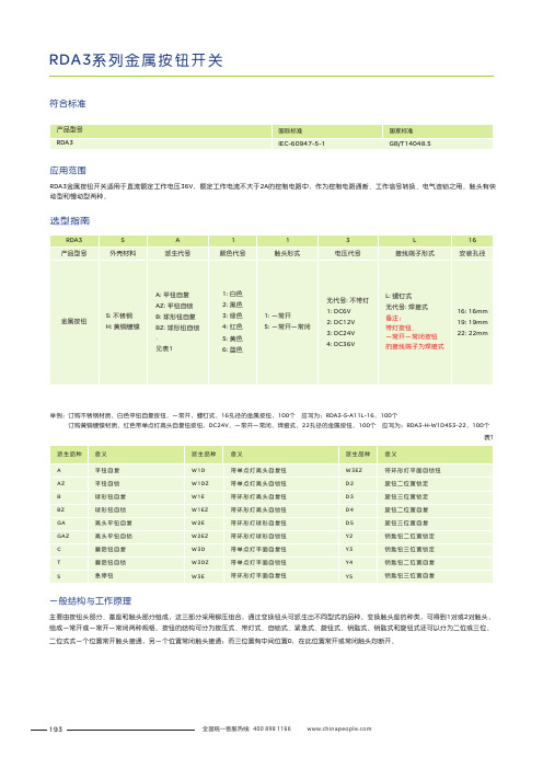
RDA3系列金属按钮开关选型指南表1举例:订购,螺钉式,16孔径的金属按钮,100个应写为:RDA3-S 100个不锈钢白色平钮自复按钮一常开黄铜镀镍红色带单点灯高头自复钮按钮一常开一常闭材质,, -A11L-16,订购材质,,DC24V ,,焊接式,22孔径的金属按钮,100个 应写为:RDA3-H-W1D453-22,100个符合标准应用范围RDA3金属按钮开关适用于直流电压36V ,额定工作电流不大于2A 的控制电路中,作为控制电路通断、工作信号转换、电气连锁之用。
触头有快动型和慢动型两种。
额定工作一般结构与工作原理主要由按钮头部分、基座和触头部分组成,这三部分采用铆压组合,通过变换钮头可派生出不同型式的品种。
变换触头座的种类,组成一常开或一常开一常闭两种规格。
按钮的结构可分为按压式、带灯式、自锁式、紧急式、旋钮式、钥匙式。
钥匙式和旋钮式还可以分为二位或三位。
二位式式一个位置常开触头接通,另一个位置常闭触头接通;而三位置有中间位置0,在此位置常开或常闭触头均断开。
可得到1对或2对触头,193外形图及尺寸平钮-选型规则螺钉式焊接式螺钉式焊接式举例:订购不锈钢,白色平钮自复按钮,一常开,螺钉式,16孔径的金属按钮 100个 应写为:RDA3-S-A11L 16 100个订购黄铜镀镍,红色平钮自锁按钮,一常闭一常闭,焊接式,22孔径的金属按钮 100个 应写为:RDA3-H-AZ4522 100个--194RDA3系列金属按钮开关外形图及尺寸球形钮-选型规则螺钉式焊接式螺钉式焊接式举例:订购不锈钢,白色球形钮自复按钮,一常开,螺钉式,16孔径的金属按钮 100个 应写为:RDA3-S-B11L 16 100个订购黄铜镀镍,红色球形钮自锁按钮,一常开一常闭,焊接式,19孔径的金属按钮 100个 应写为:RDA3-H-BZ4519 100个--195外形图及尺寸高头平钮-选型规则螺钉式焊接式螺钉式焊接式举例:订购不锈钢,白色高头平钮自复按钮,一常开,螺钉式,16孔径的金属按钮 100个 应写为:RDA3-S-GA11L16 100个订购黄铜镀镍,红色高头平钮自锁按钮,一常开一常闭,焊接式,19孔径的金属按钮 100个 应写为:RDA3-H-GAZ4519 100个--196RDA3系列金属按钮开关外形图及尺寸蘑菇钮-选型规则焊接式蘑菇钮自复、自锁举例:订购不锈钢,白色蘑菇钮自复按钮,一常开一常闭,焊接式,19孔径的金属按钮 100个 应写为:RDA3-S-C1519 100个 订购黄铜镀镍,红色蘑菇钮自锁按钮,一常开一常闭,焊接式,22孔径的金属按钮 100个 应写为:RDA3-H-T4522 100个--197外形图及尺寸急停钮-选型规则焊接式急停钮举例:订购不锈钢,红色急停钮按钮,一常开一常闭,焊接式,19孔径的金属按钮 100个 应写为:RDA3-S-S519 100个订购黄铜镀镍,红色急停钮按钮,一常开一常闭,焊接式,22孔径的金属按钮 100个 应写为:RDA3-H-S522 100个--198RDA3系列金属按钮开关外形图及尺寸带灯高钮-选型规则焊接式带单点灯带环形灯举例:订购不锈钢,白色带单点灯高头自复钮按钮,DC12V ,一常开,焊接式,16孔径的金属按钮 100个 应写为:RDA3-S-W1D11216 100个订购黄铜镀镍,红色带单点灯高头自锁钮按钮,DC24V ,一常开一常闭,焊接式,19孔径的金属按钮 100个 应写为:RDA3-H-W1DZ45319 100个--199外形图及尺寸带灯球形钮-选型规则焊接式带环形灯举例:订购不锈钢,白色带环形灯球形自复钮按钮,DC12V,一常开,焊接式,16孔径的金属按钮 100个 应写为:RDA3-S-W2E112-16 100个订购黄铜镀镍,红色带环形灯球形自复钮按钮,DC24V,一常开一常闭,焊接式,22孔径的金属按钮 100个 应写为:RDA3-H-W2EZ453-19 100个200RDA3系列金属按钮开关外形图及尺寸带灯平钮-选型规则螺钉式焊接式带环形灯带单点灯举例:订购不锈钢,白色带单点灯平面自复钮按钮,DC12V ,一常开,螺钉式,16孔径的金属按钮 100个 应写为:RDA3-S-W3D112L-16 100个订购黄铜镀镍,红色带单点灯平面自锁钮按钮,DC24V ,一常开一常闭,焊接式,22孔径的金属按钮 100个 应写为:RDA3-H-W3DZ453-22 100个201外形图及尺寸旋钮-选型规则焊接式举例:订购不锈钢,旋钮二位置锁定按钮,一常开一常闭,焊接式,19孔径的金属按钮 100个 应写为:RDA3-S-D25-19 100个订购黄铜镀镍,旋钮三位置锁定按钮,一常开一常闭,焊接式,22孔径的金属按钮 100个 应写为:RDA3-H-D35-22 100个旋钮202RDA3系列金属按钮开关外形图及尺寸钥匙钮-选型规则焊接式举例:订购不锈钢,钥匙钮二位置锁定按钮,一常开一常闭,焊接式,19孔径的金属按钮 100个 应写为:RDA3-S-Y25-19 100个 订购黄铜镀镍,钥匙钮三位置锁定按钮,一常开一常闭,焊接式,22孔径的金属按钮 100个 应写为:RDA3-H-Y35-22 100个钥匙钮203。
3535 N302B7 产品规格书说明书
产 品 规 格 书 Product Specification文件编号 Document number WE-WI-RD-962 版本版次Version editionA/0产品名称 Product name 3535内封ICN302B7产品规格Product specificationWE-3535AY0203Z-001文件编制 Documentation 马明海 批准发行Approved issue马小其客户服务 Custormer Service 联系电话 Contact number客户名称 Customer name 样品编号 Sample number产品验证 Product verification批准承认 Recognition approval注: 1.此规格书以中英文方式书写,若有冲突以中文版文本为准。
/This specification is written in both Chinese and English. In case of conflict, the Chinese version shall prevail.2.此规格书的最终解释权归由本公司。
/The final interpretation of this specification shall be vested in the company.目 录Catalog0.0、封面/co ver ..........................................................................第1页page 10.1、目录/Catalog ......................................................................... 第2页page 21、产品概述/Product Overview ..............................................................第3页page 32、功能特点/Functional characteristics.....................................................第3页page 33、应用领域/Application area ..............................................................第3页page 34、外观描述 /Appearance description ......................................................第4页page 45、封装尺寸/Size .........................................................................第4页page 46、脚位图/Foot map .........................................................................第5页page 5第5页page 5 7、最大额定值/MaximumRating ............................................................第6页page 6 8、推荐工作范围/Recommended scope ofwork .................................................9、电气参数/Electrical parameters..........................................................第6页page 610、开关特性/Switching第7页page 7 characteristics.....................................................11、内置LED参数/Built-in LED parameters..................................................第7页page 712、功能说明/Description of functions......................................................第7页page 713、恒流曲线/Constant-current第10页page 10 curve........................................................14、应用线路图/Application Route Diagram..................................................第10页page 1015、使用注意事项/Precautions ............................................................第11页page 111、产品概述/Product Overview:N302B7-3535RGB是一款集成高质量单线级联恒流驱动IC N302B7和高质量RGB LED芯片的外控恒流3535集成灯珠。
3.7×3.7×0.35超薄轻触开关薄膜锅仔按键详细规格图纸
签署(盖章) 送承认日期:.2013-12-12
客户签署(盖章) Sign for Customer Approved 确认日期: .
Reference No.
PRODUCT SPECIFICATION 产品承认书
TACT SWITCH 轻触开关
3.7*3.7*0.35 260gf
文件编号 FILE NO.
抗电强度
No dielectric breakdown shall occur.
无击穿现象发
生。
DC12V 50mA
Test Method 实验方法 在以 5V 10mA 的直流电源或不低于 1KHz 的交流电源的电路 中,以一个等于 2 倍按力的静负荷施加于手柄中心 Applying a static load of 2 times operating force to the center of the stem, measurements shall be made by 5V DC 10mA or more than 1KHZ AC small-current contact resistance meter. 在端子之间施加 DC 100V /1min 的条件下,测量端子之间底座、盖 板的电阻值 Measurement shall be made following application of 100V DC potential, across terminals, and across terminals and cover, for one minute. 250VAC (50~60Hz,cut –off current 2mA) is applied between non-connected terminals and between terminals and the metal frame for 60 ±5s. 在相互绝缘的所有接线端子之间 250V(50-60Hz ) 交流电, 各接 线端子与外壳或非载流金属零件之间加载 250V(50-60Hz ) 交流 电,持续时间 60±5S。
ALPS SSAJ系列表面贴装型开关说明书
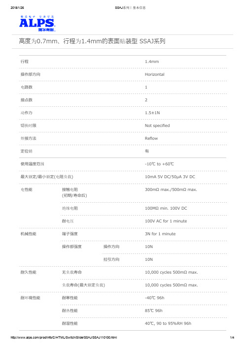
高度为0.7mm、行程为1.4mm的表面贴装型 SSAJ系列行程 1.4mm操作部方向Horizontal电路数1接点数2动作力 1.5±1N切换时限Not specified焊接方法Reflow定位销有使用温度范围‒10℃ to +60℃最大额定/最小额定(电阻负载)10mA 5V DC/50µA 3V DC300mΩ max./500mΩ max.电性能接触电阻(初期/寿命后)绝缘电阻100MΩ min. 100V DC耐电压100V AC for 1 minute机械性能端子强度3N for 1 minute操作部强度操作方向10N拉引方向10N耐久性能无负载寿命10,000 cycles 500mΩ max.负载寿命(最大额定负载)10,000 cycles 500mΩ max.耐环境性能耐寒性能‒40℃ 96h耐热性能85℃ 96h耐湿性能40℃, 90 to 95%RH 96h最小订货单位(pcs.)日本5,000出口20,000外形图焊接处尺寸图电路图包装规格载带梱包数(pcs.)1卷5,0001箱/日本10,0001箱/出口包装20,000载带宽度(mm)16出口包装箱尺寸(mm)417×409×139焊接条件回流方式的参考举例1. 加热方式远红外线加热的上下加热方式。
2. 温度测量方式用φ0.1~φ0.2的CA(K)或CC(T)测量。
位置在焊接连接部(铜箔面)测量。
固定方式采用耐热胶带。
3. 温度分布A(℃)B(℃)C(s)D(℃)E(℃)F(s)3s max.26023040180150120(1) 下述条件,为印刷电路板的零部件贴装面上的温度,根据电路板的材质,大小,厚度等,电路板温度和开关表面温度会有很大的不同,关于开关表面温度,也请在上述条件内使用。
(2) 根据回流槽的种类,条件稍有不同,请事先充分进行确认之后使用。
手工焊接方式的参考举例焊接温度350±5℃焊接时间3s max.表示本系列共通的注释。
- 1、下载文档前请自行甄别文档内容的完整性,平台不提供额外的编辑、内容补充、找答案等附加服务。
- 2、"仅部分预览"的文档,不可在线预览部分如存在完整性等问题,可反馈申请退款(可完整预览的文档不适用该条件!)。
- 3、如文档侵犯您的权益,请联系客服反馈,我们会尽快为您处理(人工客服工作时间:9:00-18:30)。
发 行编 号 : 2015101526 发 行日 期 : 2015.10.15 发行区分: 新规 改定
深圳市金东升电子科技有限公司
规格承认书
产品名称: 3.7X3.7X0.35H 平脚
接受印
ACKNOWLEDGEMENT
G.MGR
兹证明此份材料已经收到。
WE ACKNOWLEOGE RECEIVING THIS DOCUMENT .
MONTH / DAY / YEAR
DATE:
/
/
LEADER
CHECKED
SIGNED
规格承认书 品 名 3.7X3.7X0.35H 型号
260gf
1. 基本说明
1.1 范围
.此规范含盖单推柄和无推柄的轻触开关要求
1.2 使用温度范围 -20 ~70℃ 正常湿度,标准压力
1.3 保存温度范围 -40 ~85℃
弹片 防尘膜
SU S3 0 1 聚酰亚胺
银镀层
基体颜色
按力
寿命
3.7X3.7X0.35平脚
产品外形图
规格承认书
品 名 3.7X3.7X0.35H
6. 性能 6.1 电气的性能 项目
型号
测试条件
260gf
6.1.1
接触电阻
用两倍的动作力作静负载施加于按钮的中心,并用1
千赫小电流接触电阻仪测量
规格书编号
260gf
项目 6.3.8 抗冲击
测试条件
按下列条件进行冲击试验
(1)Acceleration: 80g 加速度 (2) 试验次数: 每个方向3 次,6 个方向共18 次
规格书编号
2015101526
7/8
要求
项目:6.1 6. 2.1、6.2.2
7. 焊接条件: 项目
推荐条件
请按以下条件进行焊接:
7.2 自动焊接
室温
pre-heating 预热
time 时间(秒)
time inside soldering equipment炉内通过时间
注意:以上提及的条件是零部件上PWB 表面的温度,由于PWB 的材料、尺寸、 厚度等不同,PWB 从开关表面获得的温度也会有很大产不同,因此,千万小心不 要让开关表面温度超过260℃
7.1
手工焊接 (1)焊锡温度:≤350℃
(2)连续焊接时间:≤5 S
(3)电铬铁的功率:≤20 W
对于SMT 产品,请按以下条件进行焊接
surface of product temperature 部品表面温度(℃)
230℃
180℃ 150℃
260℃ max. 3sec max. peak temperature
260gf
项目
测试条件
规格书编号
2015101526
6/8
要求
6.3.5
样品按下列条件进行高低温循环试验,试验后
在正常温度和温度条件下放置1 小时后测定
A:+85±2℃ D:1 小时
B:-40±2℃ E:2 小时
C:2 小时
F:1 小时
温度(℃)
温度循环
A
1 cycle
0℃ B
时间(hour)
C DEF
接触电阻 200mΩ . 绝缘电阻 50MΩ
项目:6.1.3、6.1.4 6. 2.1~6.2.3
6.3.3 耐低温
样品按下列条件进行耐低温试验,试验后在正常温
度和湿度条件下放置 1 小时后测定 (1) 温度: -40±2℃ (2) 时间:96h 擦除水珠
接触电阻 200mΩ . 绝缘电阻 50MΩ
9.2 封装材料
项目 转轴 载带 包装 塑料袋
说明 可降解箱 聚丙烯 瓦楞纸箱
规格书编号
2015101526
8/8
聚丙烯
销售电话:18926453388
轻触返回
3. 接触形式 1 接点 1 回路 细接点形式在装配图中
4 最大额定值 DC 12 V
50 mA
最小额定值 DC 1 V
10 μA
规格书编号
2015101526
1/8
规格承认书
品 名 3.7X3.7X0.35H
5. 外形、结构:
型号
260gf
规格书编号
2015101526
2/8
电气原理图
板焊接图
地增加负荷直到推柄停止时所测量的最大负荷
260 ±50 gf
6.2.2
行程
开关的动作方向为垂直放置开关,并以双倍动作力 的静负荷作用推柄中心,测量推柄从开始到停止的 行程距离
0.15 ± 0.05 mm
6.2.3 返回力
开关的动作方向为垂直放置开关,在已有行程的推 柄中心向上减小压力,推柄回到自由位置时所测量 到的力
1.4 测试条件
ห้องสมุดไป่ตู้测试和计量按下列标准条件除非特殊说明
标准温度 (5℃~35℃) 正常湿气 相对湿度 45% ~85% 标准压力 (860Kpa~1060Kpa) 如果出现任何问题,应在下列条件下进行测试
温度 (20±2℃) 相对湿度 (65±5%) 压力 (860Kpa~1060Kpa)
2. 动作类型
项目:6.1.3、6.1.4 6. 2.1~6.2.3
6.3.4
耐热
样品按下列条件进行耐热试验,试验后在正常温度和
湿度条件下放置 1 小时后测定 (1) 温度:85±2℃
(2) 时间: 96h
接触电阻 200mΩ . 绝缘电阻 50MΩ
项目:6.1.3、6.1.4 6. 2.1~6.2.3
规格承认书 品 名 3.7X3.7X0.35H 型号
结构图
序号
零部件名称 基座 端子
数量
材料名称 磷铜
表面处理 银镀层
备注
技术要求 塑料件表面光洁无划痕,水花,变形,影响外观及性 能等缺陷。 2.额定电流:50mA.12V DC, 绝缘电阻100M ? min.100V DC.介电强度250V AC for 1min. 接触电阻 100m ? max. 3.开关手感明显,档位清晰可靠,无卡滞现象,消除 外力后,应能快速回位。
规格承认书
品 名 3.7X3.7X0.35H 型号
260gf
8.其他注意事项: (1).进行焊接过程中,不可以用溶剂或类似品清洗开关 (2) 防止助焊剂从开关的顶端渗入 (3) 交货后保证开关处于封密状态并库存时间 90 天以下
9. 包装:
9.1 袋装\ 盘装两种.
9.1.1 范围 该规范包含 SMT 标准型轻触开关的绕带封装的要求
(1) 范围:10 频率范围振荡频率 (2 振幅: 峰-峰 1.5mm (3) 扫描周期: 10-55-10Hz 约一分钟内 (4 扫描方式:对数扫描式恒定扫描 (5) 振动方向: 3 个相互垂直方向,包括推柄行程方向 (6) 每方向2 小时.共 6 小时
项目:6.1 6. 2.1、6.2.2
规格承认书 品 名 3.7X3.7X0.35H 型号
6.1.4
抖动
Switch
DC3-5V
5kΩ
Oscillograph 示波器
10mS 以下
t
t
t 为触点抖动时间
规格承认书 品 名 3.7X3.7X0.35H 型号
6.2 机械的性能 项目
测试条件
260gf
规格书编号
2015101526
4/8
要求
6.2.1
动作力
.开关的动作方向为垂直放置开关向推柄中心逐渐
周 期: 5 次
接触电阻 200mΩ 绝缘电阻 50MΩ 项目:6.1.3、6.1.4 6. 2.1~6.2.3
6.3.6
盐雾试验
样品按下列条件进行盐雾试验
(1) 溶液浓度为:(5±1)%Nacl (2) 温度:35±2℃ (3) 时间: 24h
金属件无发黄、生锈
6.3.7 耐振动
按下列条件进行抗振动试验
(1 ) DC 5V 5mA 阻性负载 (2) 动作频率:2-3 次/每秒 (3) 380 gf 减压力 (4 动作次数: 10×104次
接触电阻 200mΩ 绝缘电阻 50MΩ
初始动作力 ±30%
项目: 6.1.3 6. 2.2
6.3.2 耐潮湿
样品按下列条件进行耐潮湿试验,试验后在正常温
度和湿度条件下放置 1 小时后测定 (1) 温度: 60±2℃ (2) 相对湿度 95% (3) 时间: 96h 擦除水珠
2015101526
3/8
要求
100mΩ以下
6.1.2
绝缘电阻 在端子与端子之间,端子与外壳之间施加DC100V,一
分钟
100MΩ以上
6.1.3
电气耐压 在端子与端子之间,端子与外壳之间施加
AC250V(50HZ-60HZ)
无击穿、闪烁现象
”. 在正常使用中(以每秒3-4 次周期)轻轻地在手柄中心
加力,在通与断瞬间测试抖动
50 gf
6.2.4 静止强度
开关的动作方向为垂直放置开关,在推柄动作方向 无机械的和电气的损伤迹
施加 1KG 的静负荷,15 秒时间
象
规格承认书 品 名 3.7X3.7X0.35H 型号
6.3 使用耐久性能 项目
测试条件
260gf
规格书编号
2015101526
5/8
要求
6.3.1
动作寿命
按下列条件进行寿命试验