labview IMAQ模块介绍
基于Labview的图像获取
基于Labview的图像获取本文详细陈述了基于Labview软件平台下,以常见的USB接口摄像头为图像获取设备,设计开发的图像实时获取并简单处理储存的虚拟仪器软件系统。
通过运用功能强大的视觉运动模块IMAQ,以图像化的程序语言完成图像获取与存储的编写。
完整的图像获取软件通过调用动态链接库(DLL),进而驱动USB接口摄像头进行所需的图像获取过程,同时将获取的的图像进行简单的处理并存储在相应的文件中。
另外,我们可以通过labview的前面板实时观察图像获取的情况并展示。
该图像获取软件系统克服了通用性差、开发时间长等缺点,具有可靠性强、灵活性高、开发门槛低、优秀的性价比等诸多优点。
关键词:Labview平台;USB摄像头;IMAQ;图像获取目录中文摘要 (I)英文摘要............................................................................................................................... I I 第一章引言....................................................................................... 错误!未定义书签。
第二章图像获取数据基本函数介绍 (3)2.1 调用库函数节点函数(call liabrary function node) (3)2.2 IMAQ Vision中子VI基本介绍 (3)2.2.1 IMAQ USB Grab Setup.vi (3)2.2.2 IMAQ Create.vi (3)2.2.3 IMAQ Dispose.vi. (4)2.2.4 IMAQ USB Stop.vi (4)2.2.5 IMAQ USB Close.vi (4)2.2.6 IMAQ USB Enumerate Cameras.vi (4)2.2.7 IMQA USB Init.vi (4)2.2.8 IMAQ USB PropertyPage.vi (4)2.2.9 IMAQ A VI Get Filter Names.vi (5)2.2.10 IMAQ A VI Create.vi (5)2.2.11 IMAQ USB Grab Acquire.vi (5)2.2.12 IMAQ Add.vi (5)2.3 LabVIEW中的程序结构介绍 (5)2.3.1 While循环 (5)2.3.2 For循环 (6)2.3.3 位移寄存器 (6)2.3.4 条件结构(Case结构) (6)2.3.5 平铺式顺序结构 (6)2.3.6 事件结构 (7)第三章图像获取程序中子VI的介绍 (8)3.1 InitCam.vi (8)3.2 InitA VI.vi (9)3.3 SaveA VI.vi (10)3.4 ReadDataCam.vi (11)第四章图像获取主VI的介绍 (13)4.1 检测USB摄像头的接入 (13)4.1.1 While循环语句 (13)4.1.2 Case结构语句 (13)4.2 程序运行部分 (13)4.2.1 事件结构的内容介绍 (14)4.2.2 图像获取过程介绍 (14)4.2.3图像获取结束 (17)4.3 关闭USB摄像头 (17)第五章最终获取的图像介绍 (18)5.1 前面板 (18)5.2 获取的图像 (18)参考文献 (23)4第一章引言Labview(Laboratory Virtual Instrument Engineering Workbench)是美国国家仪器公司(National Instruments Corporation)开发的实验室虚拟仪器集成环境。
labviewIMAQ模块介绍

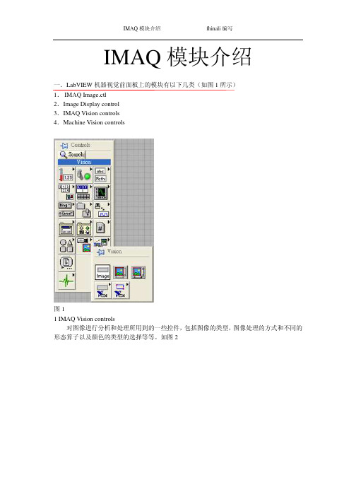
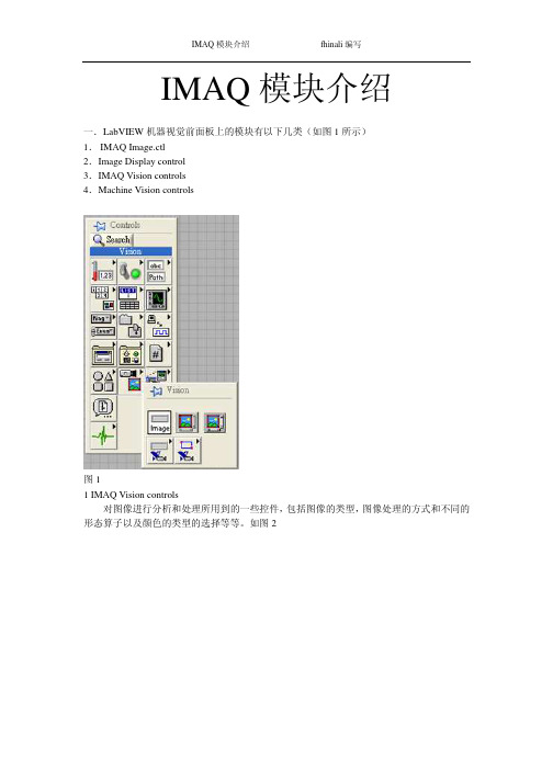
IMAQ模块介绍fhinali编写IMAQ模块介绍一.LabVIEW机器视觉前面板上的模块有以下几类(如图1所示)1.IMAQ Image.ctl2.Image Display control3.IMAQ Vision controls4.Machine Vision controls图11 IMAQ Vision controls对图像进行分析和处理所用到的一些控件,包括图像的类型,图像处理的方式和不同的形态算子以及颜色的类型的选择等等。
如图2IMAQ 模块介绍 fhinali 编写图21.1 Image Type用于图片类型的选择,可以选择的类别有8bits ,16bits ,Float ,Complex ,RGB 和HSL 。
一般用在从文件中读取图片时类型的选择。
1.2 ROI DescriptorROI 区域的描述。
ROI 是Region Of Interesting 的简称,中文应该翻译为目标区域。
一般用在一个大图中取一块特定形状的区域,以便后续的处理和分析。
ROI 为一簇数据,包括一个整数数组和一个簇组成的数组。
整数数组内有4个元素,为图形最小外接矩形的四条边的坐标。
簇数组中的簇由轮廓类型(整数),ROI 类型(整数)和图形坐标点(为数组,根据ROI 类型的不同,数组的定义也不同)1.3Optional Rectangle选择的矩形区域,为四个元素的数组,代表矩形的四条边的坐标。
1.4Color Mode色彩模式,彩色图形的显示和处理模式,包括RGB,HSL,HSV,HIS 四种。
1.5Threshold Range阀值范围,为一包含两个数组元素的簇,常用于灰度或色彩图像阀值处理模块中。
1.6 Convolution Kernel二维浮点数组成的数组,用于构造一些算法的算子。
1.7 Morphology Operation形态算法的选择。
可以选择不同的数据处理方式。
1.8 Structuring Element结构元素,为二维的整数数组。
imaq

IMAQ VISIONIMAQ Vision是LabVIEW内置的视觉开发工具包,其中包括IMAQ Vision和Vision Builder 两个组件。
IMAQ Vision是一个功能强大的函数库,提供了在LabVIEW平台上开发机器视觉系统所需要的各种子程序,例如图像采集、系统校准、图像处理、几何量测量等。
Vision Builder 是一个交互式的机器视觉系统开发环境,可以在系统软件设计的每一步看到输出的中间结果,并可以随时进行修改。
设计完成后能够自动生成LabVIEW程序代码。
NI 的IMAQ Vision 软件包为图像处理提供了完整的功能。
它将400多种功能集成到LabVIEW 和Measurement Studio(LabWindows/CVI,Visual C++及Visual Basic)开发环境中。
此外,IMAQ Vision Builder 可用于快速浏览、建立模型及测试应用,且无需编程。
NI的OCR 软件为LabVIEW 与BridgeVIEW 开发者提供了字符识别功能,可用于工业检验中读取字母。
通过交互式、可配置的软件或强大的程序库创建应用与数据采集和运动控制设备集成NI-IMAQ 驱动软件使配置和维护更简单可从LabVIEW、LabWindows/CVI、C、C++和Visual Basic中调用超过200个函数具有可配置、可编程、实时和嵌入式机器视觉的功能这个最新版本的图像软件扩充了NI的简单易用的机器视觉和图像处理工具的功能,使得流行的编程语言也能用来作图像处理。
通过IMAQ Vision 6.0,工程师们可以用Measurement Studio非常容易的创建完整的视觉检测应用程序来迅速并可靠的完成有关测量任务. Measurement Studio是一个提供各种测量工具的软件包。
所提供的工具包括数据采集,数据分析,数据图形化等. Measurement Studio支持Microsoft Visual Basic, Visual C++和ANSI标准C 语言National Instruments视觉软件产品具有机器视觉应用的众多优势。
【免费】LABVIEW-IMAQ模块中文说明书
IMAQ模块介绍一.LabVIEW机器视觉前面板上的模块有以下几类(如图1所示)1.IMAQ Image.ctl2.Image Display control3.IMAQ Vision controls4.Machine Vision controls图11 IMAQ Vision controls对图像进行分析和处理所用到的一些控件,包括图像的类型,图像处理的方式和不同的形态算子以及颜色的类型的选择等等。
如图2图21.1 Image Type用于图片类型的选择,可以选择的类别有8bits ,16bits ,Float ,Complex ,RGB 和HSL 。
一般用在从文件中读取图片时类型的选择。
1.2 ROI DescriptorROI 区域的描述。
ROI 是Region Of Interesting 的简称,中文应该翻译为目标区域。
一般用在一个大图中取一块特定形状的区域,以便后续的处理和分析。
ROI 为一簇数据,包括一个整数数组和一个簇组成的数组。
整数数组内有4个元素,为图形最小外接矩形的四条边的坐标。
簇数组中的簇由轮廓类型(整数),ROI 类型(整数)和图形坐标点(为数组,根据ROI 类型的不同,数组的定义也不同)1.3Optional Rectangle选择的矩形区域,为四个元素的数组,代表矩形的四条边的坐标。
1.4Color Mode色彩模式,彩色图形的显示和处理模式,包括RGB,HSL,HSV,HIS 四种。
1.5Threshold Range阀值范围,为一包含两个数组元素的簇,常用于灰度或色彩图像阀值处理模块中。
1.6 Convolution Kernel二维浮点数组成的数组,用于构造一些算法的算子。
1.7 Morphology Operation形态算法的选择。
可以选择不同的数据处理方式。
1.8 Structuring Element结构元素,为二维的整数数组。
2 Machine Vision controls机器视觉中用到的一些控件,只要是对图像画面进行选择的一些工具,包括点,线和面的选择以及坐标系的设定。
imaq arraytoimage的用法
imaq arraytoimage的用法IMAQ ArrayToImage函数是LabVIEW图像处理工具包中的一个函数,用于将图像数据从数组格式转换为图像格式。
它主要用于将一维或二维数组表示的图像转换为NI Vision库可以处理的图像类型。
在本文中,我将详细介绍IMAQ ArrayToImage函数的用法,并分步回答您关于该函数的问题。
首先,让我们来了解一下IMAQ ArrayToImage函数的基本语法和参数:IMAQ ArrayToImage(Array, Width, Height, Pixel Type)Array:要转换的数组,可以是一维或二维数组。
Width:图像宽度,单位为像素。
Height:图像高度,单位为像素。
Pixel Type:图像像素类型,例如8位灰度图像、24位RGB图像等。
接下来,我将详细介绍IMAQ ArrayToImage函数的用法,并回答您的问题:第一步:导入NI Vision库在LabVIEW中,首先需要导入NI Vision库,以便使用其中的图像处理函数。
您可以通过从“Functions”面板的“Vision and Motion”目录中拖放NI Vision 库中的函数模块来导入该库。
首先,您需要创建一个一维或二维的数组来表示图像。
可以使用LabVIEW的Array函数来创建一个数组,并填充它的元素。
数组的元素类型和维度应与您要转换的图像相匹配。
第三步:设置图像宽度和高度在调用IMAQ ArrayToImage函数之前,您需要确保已经准确设置了图像的宽度和高度。
这两个参数应与数组的维度匹配,以便正确地转换图像。
第四步:设置图像像素类型根据您要转换的图像的像素类型,您需要设置“Pixel Type”参数。
根据具体情况,您可以选择8位灰度图像、24位RGB图像等。
第五步:调用IMAQ ArrayToImage函数在对数组、宽度、高度和像素类型参数进行适当设置后,您可以调用IMAQ ArrayToImage函数,以便将数组转换为图像。
【免费】LABVIEW-IMAQ模块中文说明书

IMAQ模块介绍 fhinali编写IMAQ模块介绍一.LabVIEW机器视觉前面板上的模块有以下几类(如图1所示)1. IMAQ Image.ctl2.Image Display control3.IMAQ Vision controls4.Machine Vision controls图11 IMAQ Vision controls对图像进行分析和处理所用到的一些控件,包括图像的类型,图像处理的方式和不同的形态算子以及颜色的类型的选择等等。
如图2 IMAQ模块介绍 fhinali编写图21.1 Image Type用于图片类型的选择,可以选择的类别有8bits,16bits,Float,Complex,RGB和HSL。
一般用在从文件中读取图片时类型的选择。
1.2 ROI DescriptorROI区域的描述。
ROI是Region Of Interesting的简称,中文应该翻译为目标区域。
一般用在一个大图中取一块特定形状的区域,以便后续的处理和分析。
ROI为一簇数据,包括一个整数数组和一个簇组成的数组。
整数数组内有4个元素,为图形最小外接矩形的四条边的坐标。
簇数组中的簇由轮廓类型(整数),ROI类型(整数)和图形坐标点(为数组,根据ROI类型的不同,数组的定义也不同)1.3Optional Rectangle选择的矩形区域,为四个元素的数组,代表矩形的四条边的坐标。
1.4Color Mode色彩模式,彩色图形的显示和处理模式,包括RGB,HSL,HSV,HIS四种。
1.5Threshold Range阀值范围,为一包含两个数组元素的簇,常用于灰度或色彩图像阀值处理模块中。
1.6 Convolution Kernel二维浮点数组成的数组,用于构造一些算法的算子。
1.7 Morphology Operation形态算法的选择。
可以选择不同的数据处理方式。
1.8 Structuring Element结构元素,为二维的整数数组。
labview的imaq例子
labview的imaq例子
LabVIEW的IMAQ(Image Acquisition)模块是用于图像处理和分析的模块之一,主要用于图像采集、处理和分析。
在LabVIEW中,可以通过IMAQ模块来实现各种图像处理和分析的应用。
以下是几个IMAQ 的例子:
1. 图像处理例子:通过IMAQ模块对图像进行处理,比如调整亮度、对比度、增强图像细节等。
2. 图像分析例子:通过IMAQ模块对图像进行分析,比如检测图像中的目标、计算图像的特征等。
3. 视觉检测例子:通过IMAQ模块实现视觉检测应用,比如检测物体的位置、大小、形状等。
4. 工业检测例子:通过IMAQ模块实现工业检测应用,比如检测产品的质量、缺陷等。
在LabVIEW中,可以通过打开Examples菜单来查看各种示例程序,其中包括IMAQ模块的示例程序。
可以选择适合自己的应用示例,并进行相应的修改和调整。
Labview中NI-IMAQdx模块说明
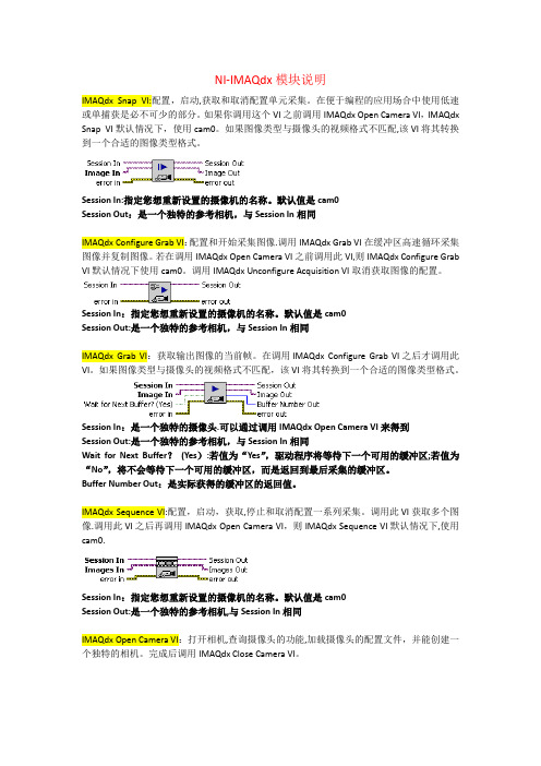
NI-IMAQdx模块说明IMAQdx Snap VI:配置,启动,获取和取消配置单元采集。
在便于编程的应用场合中使用低速或单捕获是必不可少的部分。
如果你调用这个VI之前调用IMAQdx Open Camera VI,IMAQdx Snap VI默认情况下,使用cam0。
如果图像类型与摄像头的视频格式不匹配,该VI将其转换到一个合适的图像类型格式。
Session In:指定您想重新设置的摄像机的名称。
默认值是cam0Session Out:是一个独特的参考相机,与Session In相同IMAQdx Configure Grab VI:配置和开始采集图像.调用IMAQdx Grab VI在缓冲区高速循环采集图像并复制图像。
若在调用IMAQdx Open Camera VI之前调用此VI,则IMAQdx Configure Grab VI默认情况下使用cam0。
调用IMAQdx Unconfigure Acquisition VI取消获取图像的配置。
Session In:指定您想重新设置的摄像机的名称。
默认值是cam0Session Out:是一个独特的参考相机,与Session In相同IMAQdx Grab VI:获取输出图像的当前帧。
在调用IMAQdx Configure Grab VI之后才调用此VI。
如果图像类型与摄像头的视频格式不匹配,该VI将其转换到一个合适的图像类型格式。
Session In:是一个独特的摄像头.可以通过调用IMAQdx Open Camera VI来得到Session Out:是一个独特的参考相机,与Session In相同Wait for Next Buffer?(Yes):若值为“Yes”,驱动程序将等待下一个可用的缓冲区;若值为“No”,将不会等待下一个可用的缓冲区,而是返回到最后采集的缓冲区。
Buffer Number Out:是实际获得的缓冲区的返回值。
Labview中Vision Utilities模块说明
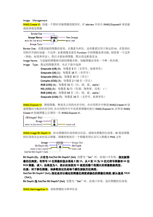
Image ManagementIMAQ Create VI:创建一个暂时存储图像的缓冲区。
在labview中结合IMAQ DisposeVI来创建或处理视觉图像Border Size:设置创建的图像的宽度,以像素为单位。
这些像素仅用于特定的VI,在您的应用程序开始时创建一个边界,如果图像是使用Function中的图像处理功能,则需要一个边界(例如,标签和形态),然后才能处理图像。
默认的边框值是3。
Image Name:与创建的图像相关联的图像名称,每幅图像必须有一个唯一的名称。
Image Type:指定的图像类型。
从以下值中选择Grayscale (U8) (0):每像素8位(无符号,标准单色)Grayscale (16) (1):每像素16位(有符号)Grayscale (SGL) (2):每像素32位(浮点)Complex (CSG) (3):每像素2×32位(浮点)RGB (U32) (4):每像素32位(红,绿,蓝,alpha)HSL (U32) (5):每像素32位(色调,饱和度,亮度,α)RGB (U64) (6):每像素64位(红,绿,蓝,alpha)Grayscale (U16) (7):每像素16位(无符号,标准单色)IMAQ Dispose VI:销毁图像,释放其占用的内存空间。
在应用程序中释放I MAQ Create VI创建图像时分配的内存空间。
在应用程序中不再需要图像时执行IMAQ Dispose VI。
在所有IMAQ Create VI创建图像之后调用一次IMAQ Dispose VI。
IMAQ Image Bit Depth VI:给出图像的位深度相关信息,或修改图像的位深度。
NI视觉图像的位深度决定如何显示图像、图像转换到另一个图像类型以及写入图像为PNG文件Bit Depth (0):只有当Get/Set Bit Depth? (Set)设置为“Set”时,此端口才有效,指定新图像的位深度。
LabVIEW 中Vision各模块说明
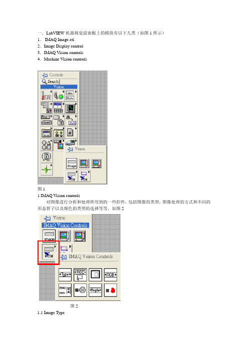
一.LabVIEW机器视觉前面板上的模块有以下几类(如图1所示)1.IMAQ Image.ctl2.Image Display control3.IMAQ Vision controls4.Machine Vision controls图11 IMAQ Vision controls对图像进行分析和处理所用到的一些控件,包括图像的类型,图像处理的方式和不同的形态算子以及颜色的类型的选择等等。
如图2图21.1 Image Type用于图片类型的选择,可以选择的类别有8bits,16bits,Float,Complex,RGB和HSL。
一般用在从文件中读取图片时类型的选择。
1.2 ROI DescriptorROI区域的描述。
ROI是Region Of Interesting的简称,中文应该翻译为目标区域。
一般用在一个大图中取一块特定形状的区域,以便后续的处理和分析。
ROI为一簇数据,包括一个整数数组和一个簇组成的数组。
整数数组内有4个元素,为图形最小外接矩形的四条边的坐标。
簇数组中的簇由轮廓类型(整数),ROI类型(整数)和图形坐标点(为数组,根据ROI类型的不同,数组的定义也不同)1.3Optional Rectangle选择的矩形区域,为四个元素的数组,代表矩形的四条边的坐标。
1.4Color Mode色彩模式,彩色图形的显示和处理模式,包括RGB,HSL,HSV,HIS四种。
1.5Threshold Range阀值范围,为一包含两个数组元素的簇,常用于灰度或色彩图像阀值处理模块中。
1.6 Convolution Kernel二维浮点数组成的数组,用于构造一些算法的算子。
1.7 Morphology Operation形态算法的选择。
可以选择不同的数据处理方式。
1.8 Structuring Element结构元素,为二维的整数数组。
2 Machine Vision controls机器视觉中用到的一些控件,只要是对图像画面进行选择的一些工具,包括点,线和面的选择以及坐标系的设定。
IMAQ Vision for LabVIEW 6.1 用户指南说明书

IMAQ Vision for LabVIEW Release Notes About IMAQ Vision for LabVIEWIMAQ Vision for LabVIEW is for engineers and scientists who are developing machine vision and scientific imaging applications.IMAQ Vision for LabVIEW is a library of powerful functions for image processing.IMAQ Vision 6.1for LabVIEW includes the following new functionalities:support for LabVIEW Real-Time,enhanced pattern matching functions,and new overlay functionality.Support for LabVIEW Real-TimeIMAQ Vision for LabVIEW introduces LabVIEW Real-Time (RT)support for IMAQ Vision and e LabVIEW RT support to create a machine vision application for a real-time,deterministic,embedded target.For information about using IMAQ Vision with LabVIEW RT,refer to the IMAQ Vision for LabVIEW Real-Time User Manual .Note In order to take advantage of the LabVIEW RT features in IMAQ Vision,IMAQ Vision Builder,and NI-IMAQ,you must purchase and install LabVIEW 6.1or later and LabVIEW Real-Time Module 6.1or later.Pattern Matching EnhancementsIMAQ Vision for LabVIEW contains updated pattern matching VIs that perform with improved accuracy.IMAQ Vision for LabVIEW also contains three new pattern matching VIs —IMAQ Advanced Setup Learn Pattern 2,IMAQ Advanced Setup Match Pattern 2,and IMAQ Refine Matches —that give you low-level control of the pattern matching algorithm.Overlay EnhancementsThe new IMAQ Merge Overlay VI merges a non-destructive overlay into an image,making the overlay part of the image content.This feature allows you to view and print the image with its overlay information from any third-party imagingsoftware.Distributing Applications that Use IMAQ VisionUse the IMAQ Vision Deployment Engine to distribute an applicationdeveloped with IMAQ Vision.The IMAQ Vision Deployment Engine isavailable separately.To distribute an application developed with IMAQVision,you must have the IMAQ Vision Deployment Engine installed onthe development machine and you must have an IMAQ Vision deploymentlicense for each target machine.Contact a National Instruments sales representative or visit topurchase the IMAQ Vision Deployment Engine and deployment licenses. About the IMAQ Vision Documentation SetIn addition to these release notes,the IMAQ Vision documentation setconsists of the following:•The IMAQ Vision Concepts Manual contains vision conceptualinformation.Read this document if you are new to vision.•The IMAQ Vision for LabVIEW User Manual contains information onhow to build vision applications using IMAQ Vision for LabVIEW.•The IMAQ Vision for LabVIEW online help contains referenceinformation about IMAQ Vision VIs.In LabVIEW,click Help»IMAQVision to access this help.•The IMAQ Vision examples help file contains links to all installedIMAQ Vision examples.In LabVIEW,click Help»Search IMAQExamples to access these example links.•The readme.txt file,which is located on the IMAQ Visioninstallation CD,contains last-minute information concerning thisrelease of IMAQ Vision for LabVIEW.•IMAQ Vision for LabVIEW Real-Time User Manual containsinstallation,configuration,acquisition,and programming informationspecific to IMAQ Vision for LabVIEW Real-Time.For your convenience,all printed IMAQ Vision documents are alsoavailable in Portable Document Format(PDF),which you can access fromthe Start»Programs»National Instruments»Vision»Documentationmenu.©National Instruments Corporation3IMAQ Vision for LabVIEW Release Notes。
基于 labVIEW 和 IMAQ 的 LCD 机器视觉精确检测系
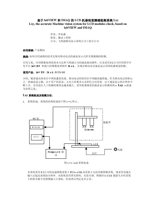
基于 labVIEW 和 IMAQ 的 LCD 机器视觉精确检测系统 Lxy Lxy, the accurate Machine vision system for LCD modules check, based onlabVIEW and IMAQ作者李春森职务测试工程师公司飞利浦移动显示系统公司上海分公司应用领域:产品测试挑战:如何应用成熟的技术实现对移动电话的液晶显示点阵实现精确的检测应用方案应用图像处理的基本方法和飞利浦公司的液晶驱动硬件以及采用NI公司应用程序开发平台labVIEW 和强大的图像处理软件IMAQ实现对移动电话液晶显示屏的机器视觉检测使用产品labVIEW; IMAQ; PCI-1408介绍随着通讯事业在中国的蓬勃发展移动电话的使用在中国越来越普遍作为移动电话的核心之一的液晶显示器由于用户的需求正向大屏幕多点及彩色方向发展由于液晶显示的分辨率不断上升对其进行人工检测的难度也越来越大采用机器视觉的液晶显示检测系统 Lxy就成为必然之选Lxy系统组成及检测方法1. 系统组成系统的结构组成如下图11所示图1 1 Lxy系统组成本系统采用NI公司的高速图像采集卡PCI1408,该采集卡支持多路图像采集现采用双镜头输入以提高系统的分辨率该系统采用背光照明光度可调图像经由CCD摄影头并经采集卡转换为数字化图像输入计算机经处理后判定是否正常2. 检测方法本系统的检测方法是采用预先经自学习产生的一系列标准图像与采集的相应图像相减并转换成为二值图的方式在经一系列的处理之后得到检测的结果并判断产品的好坏其流程如图12所示图1 2 图像处理流Lxy的图像处理及图像分析原理1. Lxy 系统照明无论进行图像处理还是进行图像分析照明条件都是最重要的外部条件对于机器视觉而言可控并恒定的光源是使检测可靠并突出检测目标的最重要的手段之一对于 LCD 检测尤其如此因为对于LCD 生产公司而言不仅检测系统的检测精度很重要检测的时间也是衡量一个机器视觉检测系统优劣的指标如果照明系统不够均匀稳定势必造成重测率的上升而影响到生产所以如何确定Lxy 系统的照明光源非常重要在Lxy 系统中采用进口FOSTEC 可调式光源20750.2并经光纤将光线引至磨砂灯板使之作为均匀并可调的背光在实践中取得了很好的效果2. Lxy 系统采集图像位置调整由于操作人员的摆放每次不同并且由于采用双镜头提高系统的分辨率所以采集图像与标准图像之间必然有位置上的差异进行位置调整的算法就必不可少如图21所示图2 1 定位模板图为定位需要经Philips 的LCD 驱动产生定位用模板图如图21所示在液晶显示矩阵的四角各显示四个定位用方形小块作为将来模板识别pattern match)时用的标准图形模板在每个镜头 的标准图像中在自学习标准图像的时候会自动将工程师定义的每个镜头的左右两个模板的图像及其坐标保存下来如图22左镜头左模板绿框内部分)则在定位用的标准图像上必有一对定位模板在检测产品时首先产生图21所示的跳图由于labVIEW具有功能强大的模板识别功能其在目标图像上搜寻图形模板的精确坐标的精度非常高所以本系统利用保存在硬盘中的模板在采集图像上进行模板识别然后将找到的模板坐标与保存在硬盘上的标准图像上相应模板的坐标进行比较就可以知道究竟采集图像有多少位移和旋转然后将将标准图像相应位移并旋转这样就可以进行图像相减了图2 2 左镜头左模3. 二值图像的处理在进行了标准图像的位置调整后经与采集图像相减得到一系列差异图像但由于照明产品差异及对位精确度等原因在每个差异图像上还需进一步处理方可得到正确的问题点经大量试验得出问题点的得出与三个因素有关分别是LCD显示矩阵的行列边缘引起的对位问题LCD透射反射膜引起的背景噪声以及照明引起的图像整体灰度平移所以在得到差异图像之后还必须对这三个方面进行处理如采用labVIEW图像处理软件中的关于图像过滤的功能过滤差异图像以去除边缘带来的对位问题对采集图像增加一个背景系数以减小噪声的影响对采集图像整体增加一灰度阀值以消除照明引起的灰度偏移产品差异的调整如下点所述这样就可将可能的问题点都提取出来了4. 产品差异的调整在LCD的生产过程中或多或少总存在产品的差异担由于机器视觉系统无法区分这些差别就必须预先对采集的图像作预调整以尽可能的减小产品差异对检测的影响本系统采用灰度整体拉伸的方法调节因为对于LCD而言总归只有黑白两种颜色对应灰度直方图则必有两个峰值分别为亮度大的峰值和亮度小的峰值如图23所示图2 3LCD灰度直方在程序中将此灰度直方图的峰值找出来将较高的一个作为调整的基点与设定的标准值( 如灰度200)相除得到的商为灰度拉伸的放大倍数然后利用labVIEW中关于图像相乘的子模块将此倍数乘采集图像所有点的灰度得到灰度拉伸之后的采集图像这样产品差异造成的影响就最大程度地得到减小解决的问题与结论由于LCD产品科技附加值大客户对产品的质量就有很高的要求以往人工检测存在人为的因素会导致误判和漏判经采用带有人工智能的机器视觉检测系统Lxy后基本排除了人为因素造成的检测问题使客户对产品的质量有了很大的信心对竞争激烈的LCD行业而言有着非同寻常的意义而在此就不能不提及NI公司的labVIEW5.1开发平台及功能强大的图像处理软件IMAQ所起的作用因为采用了以上的产品使我们的开发时间缩短很多又由于NI公司产品的重用性能良好对将来的LCD新产品相应的检测提供了广阔的发展前景。
labview IMAQ模块介绍
IMAQ模块介绍fhinali编写IMAQ模块介绍一.LabVIEW机器视觉前面板上的模块有以下几类(如图1所示)1.IMAQ Image.ctl2.Image Display control3.IMAQ Vision controls4.Machine Vision controls图11 IMAQ Vision controls对图像进行分析和处理所用到的一些控件,包括图像的类型,图像处理的方式和不同的形态算子以及颜色的类型的选择等等。
如图2IMAQ 模块介绍 fhinali 编写图21.1 Image Type用于图片类型的选择,可以选择的类别有8bits ,16bits ,Float ,Complex ,RGB 和HSL 。
一般用在从文件中读取图片时类型的选择。
1.2 ROI DescriptorROI 区域的描述。
ROI 是Region Of Interesting 的简称,中文应该翻译为目标区域。
一般用在一个大图中取一块特定形状的区域,以便后续的处理和分析。
ROI 为一簇数据,包括一个整数数组和一个簇组成的数组。
整数数组内有4个元素,为图形最小外接矩形的四条边的坐标。
簇数组中的簇由轮廓类型(整数),ROI 类型(整数)和图形坐标点(为数组,根据ROI 类型的不同,数组的定义也不同)1.3Optional Rectangle选择的矩形区域,为四个元素的数组,代表矩形的四条边的坐标。
1.4Color Mode色彩模式,彩色图形的显示和处理模式,包括RGB,HSL,HSV,HIS 四种。
1.5Threshold Range阀值范围,为一包含两个数组元素的簇,常用于灰度或色彩图像阀值处理模块中。
1.6 Convolution Kernel二维浮点数组成的数组,用于构造一些算法的算子。
1.7 Morphology Operation形态算法的选择。
可以选择不同的数据处理方式。
1.8 Structuring Element结构元素,为二维的整数数组。
LabView视觉函数 部分 中文 解释
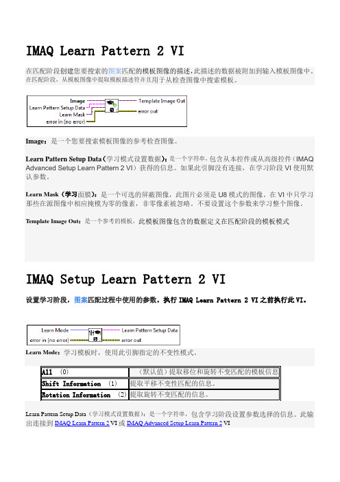
IMAQ Learn Pattern 2 VI在匹配阶段创建您要搜索的图案匹配的模板图像的描述,此描述的数据被附加到输入模板图像中。
在匹配阶段,从模板图像中提取模板描述符并且用于从检查图像中搜索模板。
Image:是一个您要搜索模板图像的参考检查图像。
Learn Pattern Setup Data(学习模式设置数据):是一个字符串,包含从本控件或从高级控件(IMAQ Advanced Setup Learn Pattern 2 VI)获得的信息。
如果此引脚没有连接,在学习阶段VI使用默认参数。
Learn Mask(学习面膜):是一个可选的屏蔽图像,此图片必须是U8模式的图像。
在VI中只学习那些在源图像中相应掩模为零的像素,非零像素被忽略。
不要设置这个参数来学习整个图像。
Template Image Out:是一个参考的模板,此模板图像包含的数据定义在匹配阶段的模板模式IMAQ Setup Learn Pattern 2 VI设置学习阶段,图案匹配过程中使用的参数。
执行IMAQ Learn Pattern 2 VI之前执行此VI。
Learn Mode:学习模板时,使用此引脚指定的不变性模式。
All(0) (默认值)提取移位和旋转不变匹配的模板信息Shift Information(1) 提取平移不变性匹配的信息。
Rotation Information(2) 提取旋转不变匹配的信息。
Learn Pattern Setup Data(学习模式设置数据):是一个字符串,包含学习阶段设置参数选择的信息。
此输出连接到IMAQ Learn Pattern 2 VI或IMAQ Advanced Setup Learn Pattern 2 VIIMAQ Setup Match Pattern 2 VIIMAQ设定匹配模式2 VI设置图案匹配的匹配阶段所使用的参数。
执行此VI前IMAQ Match Pattern 2 VI 或IMAQ Refine Matches VI。
USB摄像头与LabVIEW IMAQ USB编程实现的图像获取与处理系统说明书
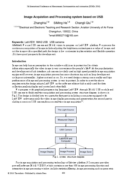
5th International Conference on Measurement, Instrumentation and Automation (ICMIA 2016)Image Acquistion and Processing system based on USBZhangHui1,a SiMing He1,a Changli Qiu1,a1,2,3,4,5Electrical and Electronic Teaching and Research Section ,Aviation University of Air ForceChangchun, 130022, Chinaa email:****************Keywords: LabVIEW IMAQ USB USB camemaAbstract. We use USB camera and IMAQ vision to program on LabVIEW platform.We process the contionuous acquistion of image,include adjusting the brightness,contrast,gamma value of image, and cut the image with a specified path.the design is low cost,easier implementation and flexible operation ,It’s have good prospects for development.IntroductionImage can help human perception to the outside world,is an important tool to obtain information,especially the video image is very convenience foe people’s life.With the popularization and development of usb interface ,usb camera is widely used as high speed,portable image acquisition equipment.However ,image acquistion process has some shortcoming such as long development cycle,poor universality , higher cost and so on .So ,we need design a strong commonality and hign performance of image and processing system is very important..In order to meet the above requirements,the design adopts LabVIEW as the software editor,which mainly used for data collection,analysis,display and control and other field.We program with graphical programming language LabVIEW,through IMAQ USB module and USB camera to finish real-time acquisition and processing,system structure diagram is shown in Fig.1.The design is divided into two parts,the first part is including a computer equipped with LabVIEW sofyware,mainly for video image display,processing and preservation,the second part in cluding a common USB camera,focus on real-time image acquistion[1].Fig.1. system structure diagramFor image acquisition and processing technology of labview platform,NI company provides powerfl software IMAQ VISION,which contains more than 400 image processing function and interactive image processing window,include statistics,filtering ,image processing,such as geometrictransformation shape matching,spot analysis and calulation and measurement application[2].It can process one-dimensional or multidimensional image and also customize according to the requirement of design personalized features.We use USB module of IMAQ VISION and USB camera to realize the video acquisttion,sedign control image operation panel,adjust the brightness of the image,contrast the gamma value ,capture image at a certain moment and save the specified durectory.the System is simple .The cycle is short, andoperation is flexible.The System Design ProcessThe front panel Process. The front panel as the labview software user interface,can effectively collect video image and display on the computer.We can adjust brightness ,contrast and gamma value,at the same time,we can capture the image and save it under the specified path. The front panel design is shown in Fig.2.Fig.2. The front panel designThe diagram Design. The program block diagram is used to implement vi logic functions,is the graphical code,as shown in Fig.3.We use attachment to corresponding function such as program,controls,constants and variables.It’s compared with the traditional text type code,not only the development is simple,but also the program is easy to understand[3].Fig.3. Theprogram panel designThe program block diagram of the process as shown in Fig.4.the program block is divided into four main function moduled,including image acquistion module,image processing module,image saving module and other functionnal modules[4].Fig.4 The program block diagram(1)Image acquistion module:Firstly,we use the output of the IMAQ USB Enumer-ate Cameras.vi connected to the strings array of usb camera,open the USB camera with IMAQ USB Init.vi,and by IMAQ USB Init.vi to open the usb camera. Secondly,we use while loop and IMAQ USB Grab Acquire.vi to collet the image continnuous,and IMAQ Creat can set the buffer space of IMAQ USB Grab Acquire.vi.Finally,we use IMAQ USB Close.vi to close the USB camera.The whole process,the image real-time display by Image Dis-play.(2)The Image processing module:We use the while loop to acquist the continuous image.We use IMAQ ColorB-CGLookup, Image Scr and Image Dst Out to connect input image and output image. Red BCG Values,GreenBCG Values and Blue BCG Values are used to change the brightness,contrast and gamma value,which can adjust the visual effect of image.(3)The save function:In the while loop,the conditional structure is used to judge whether we need screenshot.We use IMAQ WriteFile to set the save image type to PNG format,.The users can choose the srorage paths,including the select folder or new folder.Boolean controls the choice of control condition,if ture,the system automatically pop-up srore dialog box,you can customize the image name,and save the current video image;if false,wo must continues to collect images.In addition,if you select the cancel button in the dialog box,the system immediately to exit the save box,restore image acquisition function ,does not affect the program run.(4) Other modules: In the while loop,we can set the program to display the current time and ms timer.It is convenient for users to observation time by the current time mode.We can control code execution speed and reduce the CPU usage by ms timer.In addition,as long as the program runs,the red linghe has been bright,which can remind the user the program is using.Image process.Fiestly, we process the image such as gradation transformation and smoothing filter. Secondly, we separate the target from the background.Thirdly, we product template and match template image.Finally, we calculate the center of the target location[5].Dynamic image recognition. The static image has nothing to do with the time,it is the function of the position,but only a static image can’t descript the movement of objects.The moving target is imagesequence,each image is called a frame,The different image contains of relative information of camera and scenery.The image sequence uaually can be expressed as f(x,y,t),It add a time parameter t compared with static image..Because of time interval of all imge is equal ,so rhe image sequence can be expressed as f(x,y,i),It means the number of frame.We can analysis image sequence and get the motion parameters.we can use a algorithm which compare two different frame of the target image and we can know the differences because of the movement of objects. In the actual calculation process, we need subtracte the two frame target image, according to difference pixel can detect the moving object, calculate the movement of the target direction.ConclusionsCompared with traditional USB camera to collect video image,the system can not only realize the basic functions,abd when the image is darker,it is can adjust the brightness;the image is not clear,it is can adjust the contrast; γ valuealso can help to adjust the image color information,improve the image quality,making it easy for users to observe.At the same time,the system has good development and application scenarios.References[1].P. Fornaro, M. Guggisberg, T. Gyalog, Ch. Wattinger, E. Meyer and H.-J. Gntherodt. A RemoteControllable and Programmable Atomic Force Microscope based on LabVIEW.(2008)[2]. George C Panayi, Alan C Bovik and Umesh Rajashekar.Image Processing for Everyone.(2010)[3]National Instruments.《IMAQ Vision User's Manual》.(2011).[4]Wang Zhixiao,Dong Fuguo.Realization of Virtual Oscillograph Based on USB.The Eighth International Conference on Electronic Measurement and Instruments,Xi’an,2007[5]LabVIEW Advanced performance&Communication Course Manual[J].National instruments,2013.。
LabVIEW软件介绍解析

15
“新建” 对话框
16
Menu
File Edit Operate Tools Browse Window Help
快捷菜单 Shortcut Menus for Front Panel Objects
Right-click the label to access its shortcut menu
4
The LabVIEW Family
NI LabVIEW
Graphical Programming Software for Measurement and Automation
LabVIEW Real-Time Module LabVIEW FPGA Module
LabVIEW PDA Module LabVIEW Datalogging and Supervisory Control Module
August 2000
• LabVIEW 6i Internet-ready measurement intelligence
March 1998
• LabVIEW 5.0 ActiveX, Multithreading
February 1996 • LabVIEW 4.0 Added professional tools, improved debugging
Resize ring
Additional Buttons on the Block Diagram Toolbar
Reorder ring Context Help Button
基于LabVIEW 的实时监控视频调用的三种模型研究

基于LabVIEW的实时监控视频调用的三种模型研究杨慧闻,张嘉琪(天津理工大学环境科学与安全工程学院,天津300384)摘要:当前各行业的各种类型的监控摄像头的安装越来越普及,在交通测流、检测车辆违章、银行安保、工厂运行监控、产品加工等各方面都需要进行实时监控,并且对所获取到的监控视频进行分析和视觉应用(包括但不限于测量测定、颜色处理、识别处理、定位引导等),为了解决监控摄像头的实时监控影像的在LabVIEW中的调用,提出了三种基于LabVIEW平台上的针对两种不同类型(ip摄像头,usb摄像头)的监控视频画面的实时调用,利用LabVIEW平台的视觉图像处理模块VDM(Vision Development Module)、视频流SDK二次开发、VLC多媒体播放器调用等技术编写程序模型,实现实时监控画面在LabVIEW中的调用。
关键词:实时预览;LabVIEW;SDK二次开发;VDM中图分类号:TP311.1文献标识码:A文章编号:1009-3044(2020)36-0238-05开放科学(资源服务)标识码(OSID):Research on Three Models of Real-time Monitoring Video Call Based on LabVIEWYANG Hui-wen,ZHANG Jia-qi(School of Environmental Science and Safety Engineering,Tianjin University of Technology,Tianjin300384,China) Abstract:at present,the installation of various types of surveillance cameras in various industries is becoming more and more popu⁃lar,which needs real-time monitoring in traffic flow measurement,vehicle violation detection,bank security,factory operation mon⁃itoring,product processing and other aspects,as well as analysis and visual application of the obtained surveillance video(includ⁃ing but not limited to measurement and measurement,color processing,identification processing,setting In order to solve the call of the real-time monitoring image of the monitoring camera in LabVIEW,three kinds of real-time calls for two different types of monitoring video images(IP camera,USB camera)based on LabVIEW platform are proposed,and the vision development module VDM(vision development)of LabVIEW platform is used Module),secondary development of video stream SDK,call of VLC multi⁃media player and other technologies are used to write program models to realize the call of real-time monitoring screen in Lab⁃VIEW.Key words:Live preview;LabVIEW;SDK secondary development;VDM1背景当前随着我国经济的快速发展和消费者安全意识的逐渐提高,各个行业的根据其自身需求,都会大量使用到各种类型的实时监控摄像头,促使监控摄像头在视频影像主流应用层面快速发展。
IMAQ Vision for LabVIEW版本6.0系统要求说明说明书

IMAQ ™,LabVIEW ™,National Instruments ™,and ™are trademarks of National Instruments Corporation.Product and company names mentioned herein are trademarks or trade names of their respective companies.322363B-01©Copyright 1999,2000National Instruments Corp.All rights reserved.October 2000IMAQ V ISION FOR L AB VIEWVersion 6.0IMAQ Vision for LabVIEW adds multipurpose image processing and machine vision capabilities to LabVIEW.These release notes describe system requirements,provide installation instructions,and contain updated information about IMAQ Vision for LabVIEW.System RequirementsTo run IMAQ Vision 6.0on your machine,you must have the following minimum system requirements:•Microsoft Windows 2000/NT version 4.0or Windows Me/9x •50MB or more of free hard disk space •32MB RAM or more •NI-IMAQ 2.2or higher if you use NI-IMAQ driver software •LabVIEW 5.1or higher Note Consult the LabVIEW release notes for the required system configurations for LabVIEW.Installation InstructionsFollow these instructions to install IMAQ Vision 6.0on your computer:1.Insert the IMAQ Vision for LabVIEW installation CD.2.If you do not have autorun enabled,double-click on setup.exe .If you have autorun enabled,setup.exe runs automatically.3.Follow the instructions on yourscreen.Distributing Applications that Use IMAQ VisionIf you want to distribute an application developed with IMAQ Vision,use the IMAQ Vision Deployment Engine.Before distributing an application developed with IMAQ Vision,youmust have the IMAQ Vision Deployment Engine and an IMAQ Visiondeployment license for each target machine.Contact yourNational Instruments sales representative or visit to purchasedeployment licenses.New FunctionalityThis section briefly summarizes the new functionality found in version6.0of IMAQ Vision for LabVIEW.Palette ReorganizationIMAQ Vision features reorganized palettes that create an easy interfacefor developing machine vision applications.There are three main palettesof IMAQ Vision VIs:Vision Utilities,Image Processing,and MachineVision.The Vision Utilities palette contains VIs for creating and disposingimages,display,image and pixel manipulation,calibration,and region ofinterest tools.The Image Processing palette contains a wide range of VIsfor processing and analyzing color,grayscale,and binary images.The Machine Vision palette contains new high-level machine vision VIs,as well as VIs for pattern matching,analytic geometry,and instrumentreading.Color Pattern MatchingUse color pattern matching to quickly locate known reference patterns,or fiducials,in a color image.Color pattern matching can simplify amonochrome problem by improving contrast or separation of the objectfrom the background.Color pattern matching expands the powerfulIMAQ Vision grayscale pattern matching feature by locating patternsthat can be distinguished only by color.In some cases,the extra colorinformation allows the algorithm to find patterns more quickly than withgrayscale pattern matching.Color pattern matching also providesextremely quick color location solutions.IMAQ Vision for LabVIEW Release CalibrationUse IMAQ Vision spatial calibration functions to calibrate your image totake accurate,real-world measurements from images,regardless of cameraperspective or lens distortion.You can set simple calibration data by handor let IMAQ Vision automatically learn the calibration data for an image.You can then convert from pixels to real-world coordinates for simplemeasurements or correct the image so you can do complex measurements,such as blob analysis.Machine Vision VIsIMAQ Vision6.0includes a new palette of high-level machine vision VIsto simplify common machine vision tasks,such as selecting regions ofinterest in the shapes of points,lines,rectangles,and annuluses.Othermachine vision VIs give you the ability to define coordinate systems basedon features in an image,which allows you to make reliable measurementseven as objects in your image move and change orientation.Functions thatcount and measure objects,measure intensities,measure distances betweenedges,and locate edges all make machine vision tasks easier than ever.Analytic Geometry FunctionsThe new analytic geometry functions provide common analytic geometryalgorithms,such as line fitting with outlier rejection,circle and ellipsefitting,calculating line intersections,bisecting lines,and finding the anglebetween lines.You can also use them to calculate polygon areas,get pointsalong a line or region of interest,and create a coordinate reference systembased on an arbitrary plane.Regions of InterestTwo new regions of interest—the rotated rectangle and the annulus—give you more flexibility in selecting particular regions in an image forprocessing and analysis.These new regions work with all new machinevision VIs and existing functions.Image Display OptionsIMAQ Vision6.0allows you to specify display options for16-bit grayscaleimages.You can choose to bitwise-shift the pixel values to use the mostsignificant bits,choose to have IMAQ Vision automatically use thedynamic range of pixel values in an image to scale the image to an8-bitrange,or choose to specify a user-defined range of pixel values todynamically scale into an8-bit range.©National Instruments Corporation3IMAQ Vision for LabVIEW Release NotesAbout Your IMAQ Vision Documentation SetIn addition to these release notes,the IMAQ Vision documentation setconsists of the following:•The IMAQ Vision Concepts Manual contains vision conceptualinformation.Read this document if you are new to vision.•The IMAQ Vision for LabVIEW User Manual contains information onhow to build your vision applications using IMAQ Vision forLabVIEW.•The IMAQ Vision for LabVIEW online help(from inside theLabVIEW environment:Help»IMAQ Vision)contains referenceinformation about IMAQ Vision VIs.•The IMAQ Vision examples help file(from inside the LabVIEWenvironment:Help»Search IMAQ Examples)contains links to allinstalled IMAQ Vision examples.•The readme.txt file(located on your IMAQ Vision installation CD)contains last-minute information concerning this release of IMAQVision for LabVIEW.For your convenience,all IMAQ Vision documentation is also availablein PDF format,which you can access from the Start»Programs»National Instruments»Vision»Documentation menu.。
LabView部分视觉函数中文解说

IMAQ Learn Pattern 2 VI在匹配阶段创建您要搜索的图案匹配的模板图像的描述,此描述的数据被附加到输入模板图像中。
在匹配阶段,从模板图像中提取模板描述符并且用于从检查图像中搜索模板。
Image:是一个您要搜索模板图像的参考检查图像。
Learn Pattern Setup Data(学习模式设置数据):是一个字符串,包含从本控件或从高级控件(IMAQ Advanced Setup Learn Pattern 2 VI)获得的信息。
如果此引脚没有连接,在学习阶段VI使用默认参数。
Learn Mask(学习面膜):是一个可选的屏蔽图像,此图片必须是U8模式的图像。
在VI中只学习那些在源图像中相应掩模为零的像素,非零像素被忽略。
不要设置这个参数来学习整个图像。
Template Image Out:是一个参考的模板,此模板图像包含的数据定义在匹配阶段的模板模式IMAQ Setup Learn Pattern 2 VI设置学习阶段,图案匹配过程中使用的参数。
执行IMAQ Learn Pattern 2 VI之前执行此VI。
几何图案学习创建一个匹配阶段您要搜索的的模板图像的描述。
此数据被附加到描述输入模板图像。
在匹配阶段,描述数据从模板图像中提取,并用于检查图像中并搜寻模板。
Origin Offset(原点偏移):指定的VI模板图像的中心与模板的起偏移的像素数。
原点偏移用于IMAQ Match Geometric Pattern 2VI设置每个模板匹配的匹配结果集内的目标图像的元素位置,默认值是(0,0),设置的模板图像的中心作为原点的模板Template Image:是一个在匹配阶段您要搜索检查模板图像的参考图像。
Learn Geometric Pattern 2 Setup Data(几何图案学习的设置数据):是一个字符串,其中包含从IMAQ Setup Learn Geometric Pattern 2 VI或IMAQ Advanced Setup Learn Geometric Pattern 2 VI获得的信息。
基于Labview的图像获取
基于Labview的图像获取本文详细陈述了基于Labview软件平台下,以常见的USB接口摄像头为图像获取设备,设计开发的图像实时获取并简单处理储存的虚拟仪器软件系统。
通过运用功能强大的视觉运动模块IMAQ,以图像化的程序语言完成图像获取与存储的编写。
完整的图像获取软件通过调用动态链接库(DLL),进而驱动USB接口摄像头进行所需的图像获取过程,同时将获取的的图像进行简单的处理并存储在相应的文件中。
另外,我们可以通过labview的前面板实时观察图像获取的情况并展示。
该图像获取软件系统克服了通用性差、开发时间长等缺点,具有可靠性强、灵活性高、开发门槛低、优秀的性价比等诸多优点。
关键词:Labview平台;USB摄像头;IMAQ;图像获取目录中文摘要 (I)英文摘要............................................................................................................................... I I 第一章引言....................................................................................... 错误!未定义书签。
第二章图像获取数据基本函数介绍 (3)2.1 调用库函数节点函数(call liabrary function node) (3)2.2 IMAQ Vision中子VI基本介绍 (3)2.2.1 IMAQ USB Grab Setup.vi (3)2.2.2 IMAQ Create.vi (3)2.2.3 IMAQ Dispose.vi. (4)2.2.4 IMAQ USB Stop.vi (4)2.2.5 IMAQ USB Close.vi (4)2.2.6 IMAQ USB Enumerate Cameras.vi (4)2.2.7 IMQA USB Init.vi (4)2.2.8 IMAQ USB PropertyPage.vi (4)2.2.9 IMAQ A VI Get Filter Names.vi (5)2.2.10 IMAQ A VI Create.vi (5)2.2.11 IMAQ USB Grab Acquire.vi (5)2.2.12 IMAQ Add.vi (5)2.3 LabVIEW中的程序结构介绍 (5)2.3.1 While循环 (5)2.3.2 For循环 (6)2.3.3 位移寄存器 (6)2.3.4 条件结构(Case结构) (6)2.3.5 平铺式顺序结构 (6)2.3.6 事件结构 (7)第三章图像获取程序中子VI的介绍 (8)3.1 InitCam.vi (8)3.2 InitA VI.vi (9)3.3 SaveA VI.vi (10)3.4 ReadDataCam.vi (11)第四章图像获取主VI的介绍 (13)4.1 检测USB摄像头的接入 (13)4.1.1 While循环语句 (13)4.1.2 Case结构语句 (13)4.2 程序运行部分 (13)4.2.1 事件结构的内容介绍 (14)4.2.2 图像获取过程介绍 (14)4.2.3图像获取结束 (17)4.3 关闭USB摄像头 (17)第五章最终获取的图像介绍 (18)5.1 前面板 (18)5.2 获取的图像 (18)参考文献 (23)4第一章引言Labview(Laboratory Virtual Instrument Engineering Workbench)是美国国家仪器公司(National Instruments Corporation)开发的实验室虚拟仪器集成环境。
- 1、下载文档前请自行甄别文档内容的完整性,平台不提供额外的编辑、内容补充、找答案等附加服务。
- 2、"仅部分预览"的文档,不可在线预览部分如存在完整性等问题,可反馈申请退款(可完整预览的文档不适用该条件!)。
- 3、如文档侵犯您的权益,请联系客服反馈,我们会尽快为您处理(人工客服工作时间:9:00-18:30)。
IMAQ模块介绍fhinali编写IMAQ模块介绍一.LabVIEW机器视觉前面板上的模块有以下几类(如图1所示)1.IMAQ Image.ctl2.Image Display control3.IMAQ Vision controls4.Machine Vision controls图11 IMAQ Vision controls对图像进行分析和处理所用到的一些控件,包括图像的类型,图像处理的方式和不同的形态算子以及颜色的类型的选择等等。
如图2IMAQ 模块介绍 fhinali 编写图21.1 Image Type用于图片类型的选择,可以选择的类别有8bits ,16bits ,Float ,Complex ,RGB 和HSL 。
一般用在从文件中读取图片时类型的选择。
1.2 ROI DescriptorROI 区域的描述。
ROI 是Region Of Interesting 的简称,中文应该翻译为目标区域。
一般用在一个大图中取一块特定形状的区域,以便后续的处理和分析。
ROI 为一簇数据,包括一个整数数组和一个簇组成的数组。
整数数组内有4个元素,为图形最小外接矩形的四条边的坐标。
簇数组中的簇由轮廓类型(整数),ROI 类型(整数)和图形坐标点(为数组,根据ROI 类型的不同,数组的定义也不同)1.3Optional Rectangle选择的矩形区域,为四个元素的数组,代表矩形的四条边的坐标。
1.4Color Mode色彩模式,彩色图形的显示和处理模式,包括RGB,HSL,HSV,HIS 四种。
1.5Threshold Range阀值范围,为一包含两个数组元素的簇,常用于灰度或色彩图像阀值处理模块中。
1.6 Convolution Kernel二维浮点数组成的数组,用于构造一些算法的算子。
1.7 Morphology Operation形态算法的选择。
可以选择不同的数据处理方式。
1.8 Structuring Element结构元素,为二维的整数数组。
Edited by Foxit ReaderCopyright(C) by Foxit Software Company,2005-2008For Evaluation Only.2 Machine Vision controls机器视觉中用到的一些控件,只要是对图像画面进行选择的一些工具,包括点,线和面的选择以及坐标系的设定。
如图3所示2.1 Point点的选择,包括两个元素的簇,分别为横坐标和纵坐标。
2.2 Line线的选择,包括四个元素的簇,分别为起点和终点的横坐标和纵坐标。
2.3 Rectangle面的选择,包括五个元素的簇,分别为对角线两点横坐标和纵坐标,以及矩形选择的角度。
2.4 Circle环形面,包括六个元素的簇,分别为圆心坐标,内外半径的长度以及起始角和终止角。
图3二以上都是程序前面板上所用到的控件,而LabVIEW强大的图像处理功能都是通过其程序面板上的功能节点来实现的。
主要的节点可以分为以下四大类,如图41 Image Acquisition2 Vision Utilities3 Image Processing4 Machine Vision图41 Image Acquisition图像采集功能模块,主要是通过NI的系列图像采集板卡来获得图像。
节点包括任务的建立,设备的初始化以及硬件参数的设定等功能节点。
如图5图52 Vision Utilities视觉应用模块,用来对图像进行一些初步的整体操作。
如图6IMAQ 模块介绍 fhinali 编写图62.1 Image Management图像管理模块,包括建立和清除图像任务,获取图像的各类信息,图像的类型转换等功能节点。
如图72.1.1Create 创建一个图像任务 2.1.2Dispose 清除图像任务2.1.3Get Image Size 获得图像的大小信息 2.1.4Set Image Size 设置图像的大小2.1.5Get Image Info 获得图像信息,包括图像的大小,名称,分辨率等 2.1.6Copy 拷贝图像2.1.7Image to Image 一个图像映射到另一个图像上2.1.8Get Offset 针对于mask 而言。
获得Mask 在图像中的偏移量。
2.1.9Set Offset 针对于mask 而言。
设定Mask 在图像中的偏移量。
2.1.10Cast Image 图像类型的转换。
2.1.11 Is Vision Info Present 判断图像中是否存在图像信息。
Edited by Foxit ReaderCopyright(C) by Foxit Software Company,2005-2008For Evaluation Only.图72.2Files图像文件模块,完成对图像文件的读写,以及图像附加信息的读写操作。
图82.2.1Read File读取图像文件2.2.2Write File保存图像文件2.2.3Get File Info获得图像信息,包括图像的类型,分辨率大小2.2.4Write BMP File保存为BMP图像文件2.2.5Write JPEG File保存为JPEG图像文件2.2.5Write PNG File保存为PNG图像文件2.2.5Write TIFF File保存为TIFF图像文件2.2.6Read Image And Vision Info 读取图像及其附加信息。
2.2.7Write Image And Vision Info 保存图像及其附加信息。
2.3External Display图像的外部显示。
具体功能还不太清楚。
如图9所示图92.4Region of InterestROI模块,主要完成ROI和Mask之间的转化,ROI区域的设定以及在不同坐标系下的转换。
10如图图102.4.1ROIToMask2.4.2MaskToROI以上两者Mask和ROI之间的相互转换。
在一些图像的分析模块中,除了要求输入图片外,还要一个Mask,即只对图片中的Mask区域进行分析,这就要求把自己选择的ROI转换为Mask。
2.4.3Group ROIs把多个ROI数组转换为一个ROI区域。
其中转换后的ROI区域包含原ROI 数组的所有区域。
2.4.4Ungroup ROIs为2.4.3Group ROIs的逆运算,即把一个ROI区域转换为ROI数组,数组中的每个ROI都是一个图形轮廓。
2.4.5 TransformROI把ROI区域从一个坐标系转换为另一种坐标系中。
2.4.6 ROI Conversion ROI和各种点、线、面等各类图形之间的转换。
2.5Image Manipulation11图像处理模块。
包括图像的放大和缩小,平移以及旋转。
如图图112.5.1 Resample重新定义图像的大小,使用此模块可以放大或缩小图像。
2.5.2 Expand 通过调整整幅或一部分图片的分辨率,来放大图片。
2.5.3 Extract 通过调整整幅或一部分图片的分辨率,来缩小图片。
2.5.4 Interlace 分别提取一幅图像的奇偶像素,分成两幅图片。
2.5.5 Symmetry 得到一幅图像的对称图像2.5.6 Rotate得到一幅图像的旋转图像2.5.7 Shift 得到一幅图像的平移图像2.5.8 Unwrap 将环形的图片展开成矩形2.5.9 Clipboard To Image将剪贴的数据拷贝到图像2.5.10 Image To Clipboard 将图像拷贝到剪贴板2.5.11 3DView将图像进行三维变换2.6Pixel Manipulation图像像素处理模块。
对图像的像素直接进行操作,包括图像上点,线,面像素值的获取和设定,以及在图像中插入文本。
如图12图122.6.1 Get pixel value获得图像中某一点的像素值,仅限于灰度图像。
2.6.2 GetRowCol获得图像中某一行或者列的像素值,仅限于灰度图像2.6.3 GetPixelLine获得图像中某一条直线的像素值,仅限于灰度图像2.6.4 ImageToArray将图像转化为数组2.6.5 SetPixelValue 设置图像中某一点的像素值。
2.6.6 SetRowCol 设置图像中某一行或者列的像素值2.6.7 SetPixelLine 设置图像中某一条直线上点的像素值2.6.8 ArrayToImage 将数组转化为图像2.6.9 FillImage将图像中的某块区域用像素值填充2.6.10 Draw 在图像中绘制几何图形2.6.11 Draw Text在图像中添加文字2.7Overlay图像覆盖模块。
可以对图像上的某一点,线,面(多边形,矩形和圆)进行覆盖。
此种覆盖为非破坏性的覆盖,即不破坏原有的图像,覆盖信息可以另外和图像一起保存。
如图13IMAQ 模块介绍 fhinali 编写图132.7.1 Overlay Points 在图像中覆盖一点或是一组点 2.7.2 Overlay Line 在图像中覆盖一条线2.7.3 Overlay Multiple Lines 在图像中覆盖多条直线或多边形 2.7.4 Overlay Rectangle 在图像中覆盖一矩形 2.7.5 Overlay Oval 在图像中覆盖一椭圆 2.7.6 Overlay Arc 在图像中覆盖一弧形 2.7.7 Overlay Bitmap 在图像中覆盖一位图 2.7.8 Overlay Text 在图像中覆盖文字 2.7.9 Clear Overlay 在图像中清除覆盖 2.7.10 Copy Overlay 在图像中拷贝覆盖 2.7.11 Overlay ROI 在图像中覆盖ROI 区域 2.7.12 Merge Overlay 合并图像中的覆盖2.7.13 Read Image And Vision Info 读取图像以及图像信息 2.7.14 Write Image And Vision Info 写入图像以及图像信息上述读写图像及信息的模块,是将图像中的覆盖信息一块读取/保存的2.8Calibration 校准模块。
校准由于相机镜头的光学畸变而或拍摄角度引起图像变化。
也包含像素坐标系和实际坐标系之间的转换节点。
如图14Edited by Foxit ReaderCopyright(C) by Foxit Software Company,2005-2008For Evaluation Only.图142.8.1 Learn Calibration Template对校准模块进行学习2.8.2 Set Simple Calibration 对校准的设置2.8.3 Set Calibration Info 设置图像校准的信息2.8.4 Get Calibration Info 获得图像校准中的信息2.8.5 Convert Real World to Pixel 将实际坐标系转化为图像像素坐标系2.8.6 Convert Pixel to Real World 将图像像素坐标系转化为实际坐标系2.8.7 Correct Calibrated Image对图像进行校准2.8.8和2.8.9与2.7.13和2.7.14模块相同。