天任触摸屏手册
《触摸屏手册》word版

WEINVIEW触摸屏实训简明手册目录触摸屏简介 (2)触摸屏实训 (3)一、实训目的 (3)二、实训器材 (3)三、实训指导 (4)四、实训要求 (7)五、软元件分配及系统接线图 (7)六、触摸屏画面设计 (7)七、PLC程序 (15)八、程序调试 (16)九、实训报告 (16)触摸屏简介MT500系列触摸屏,是专门面向PLC应用的,不同于一些简单的仪表式或其它的一些简单的控制PLC的设备,它继承了传统触摸屏的优点,其功能非常强大,使用非常方便。
MT500系列触摸屏硬件规格:1.24V供电,工作电流小于400mA。
2.高可靠性的触控面板。
3.32位RISC处理器。
4.可直接连接市场上大多数PLC以及变频器,温控表,单片机等连接。
5.TFT高对度、高亮度的LC显示器,支持256种色彩。
6.支持主-从通讯协议。
7.可同时使用两种不同端口与两种不同协议PLC或其它设备通讯。
MT500系列触摸屏组态软件:1.用户组态软件为EasyBuiler500,最新版本为V2.7.22.具备一般触摸屏组态软件的功能。
3.强大的模拟功能,有离线模拟、连接模拟、直接连线模拟、使用副站的方式进行直接连接模拟四种功能。
4.主-从通讯功能。
当一台MT500连接到PLC后,其余的MT500都可以通过它来获取PLC数据。
5.强大的图形编辑功能,支持画面水平/垂直模式显示、多国语言显示等功能。
6.宏指令功能,使用VB Script语法,让用户能够建立起自己的程序以实现特定的功能。
触摸屏实训实训课题触摸屏控制PLC输入输出点及电动机的正反转一、实训目的(1)了解触摸屏相关知识,掌握触摸屏的简单应用;(2)熟悉EasyBuiler500软件的使用,掌握图形、对象的操作和属性的设置;(3)掌握PLC 和触摸屏相关联的程序编制。
二、实训器材(1)可编程控制器1台(FX 2N -48MR ); (2)MT506TV46WV 触摸屏1台; (3)电动机1台; (4)接触器2个;(5)触摸屏用DC 24V 电源,也可用PLC 输出DC 24V ;(6)计算机1台(已安装GX 或GPP 和EasyBuiler500软件); (7)导线若干。
【精品】触摸屏操作手册

触摸屏操作手册中国·湖南·长沙市拓创科技发展有限公司2008。
01。
121.1、系统开机1.2、送控制柜电源,观察面板中间的触摸屏上电源灯及DC24V指示灯是否有显示,如无显示请检查电源输入是否正常。
1.3、检查药剂贮存池的存药情况。
1.4、打开进给药箱的进药开关。
1.5、开始加药:将操作柜上“加药机"开关置于“开"的位置,上方运行指示灯亮,系统开始加药。
系统开始加药后请到给药室检查各药点的执行阀工作是否正常。
触摸屏操作说明当主机通电开机以后,在触摸屏上显示如图一所示启动主画面.(图一)PWE灯为触摸屏的电源指示灯,CPU灯亮表示触摸屏正在运行,COM灯闪烁表示触摸屏与PLC通迅正常.在屏幕共设置了[流量设定]、[累计量显示]、[参数设定]、[动作状态]等四个功能启动按钮,点击各功能键就可进入相应的功能模块.点击[流量设定]按钮可进入各药点的流量设定屏幕,点击[累计量显示]按钮可进入各药点的已设定的阀容、一次时间参数和药耗累计量监视,点击[参数设定]按钮进入阀门的工作参数、触摸屏系统时间设定.点击[动作状态]按钮可监视到各加药点工作和PLC输入的运行状态等.2.1、药点流量设定值的输入操作:点击主画面中[流量设定]按钮进入了如下图所示的流量设定画面。
(图二)在此画面中显示的为8个药点的[设定量]、[最大量]、[最小量]和[实际量]分别为对应加药地址给药阀的当前设定流量、最小量添加量、最大量添加量、阀门实际流量数。
[最大量]、[最小量]栏中显示数据是由[参数设定]屏幕并且具有操作权限的技术人员来设定的;[实际量]为阀门实际流量数,[设定量]栏中的数据可以按以下操作进行修改。
2.1。
1、点击屏幕中要修改的添加地址对应的流量数栏,右边的地址区即弹出一个数字健盘.2.1.2、点击右边键盘中的数字键输入合适的流量数(最大量和最小量之间数据)后按[ENT]输入的数据被写入PLC,数字健盘即消失;按[ESC]取消当前操作,数字健盘即消失.2.1.3、当输入的流量数为[0]时(或将暂停开关打到关的位置),则该药点停止加药。
Skyfold 触摸屏用户手册说明书

The following procedures apply to normal operating situations. For additional information on the Skyfold system, please refer to your owner’s manual. Warning• T wo operators, one per touch screen on both sides of the wall, are required for the duration of the wall operation. Ensure that both operators of the Skyfold wall havea clear and unobstructed view of the wall. The Skyfold wall must be monitored from both sides of the wall for the extent of the wall’s ascent or descent, as this can prevent injury and/or damage to the Skyfold wall.• D o not place objects between the panels, underneath the Skyfold wall, or in the near vicinity of the Skyfold wall, as this can cause damage to the Skyfold wall when itis in motion.• D o not operate your Skyfold wall with persons or objects in the path or immediate vicinity of the Skyfold wall, and ensure that the area around both sides of the Skyfold wall is clear from obstructions.• I n case of a malfunction, do not operate the Skyfold wall or attempt to repair it. Call your local authorized Skyfold dealer for service.• D o not operate your Skyfold wall if it is making any abnormal noises or if the Skyfold wall does not appear to be working properly. Contact your local authorized Skyfold dealer immediately.• D o not operate your Skyfold wall if panels are missing as this can damagethe system.• H eat generated by lights inside of the ceiling pocket can damage the panels. Therefore, you must turn on lights that are located in the Skyfold ceiling pocket only when the wall is completely down. Never turn on the lights located in the Skyfold ceiling pocket when the wall is partially or fully retracted into the pocket.• I n cases where an obstruction has caused the Skyfold wall to halt its descent, it will raise automatically (auto-reverse) for 3 seconds to clear the obstruction. You must then remove the obstruction prior to resuming the wall’s descent.Touch the screen to activate thekeypad and display the SKYFOLDsplash screen. Touch the screenagain to proceed to the “PasswordEntry” page or wait 3 seconds.An alpha numeric keypad will nowbe displayed. Enter the default userpassword “4753”. Press “√” once thepassword has been entered. Pleasenote, an additional password can beadded in the settings menu (see step 5).The “Agreement” screen is nowdisplayed on both touch screens.Please read the message and followthe instructions. Once ready, press“Agree” on both touch screens.23Figure 1, Splash ScreenFigure 2, Password Entry ScreenFigure 3, Safety WarningYou can now operate your Skyfold wall. The operator who entered the password will have the “Wall Operation” screen displayed (Figure 4).The “Enable Button” screen will bedisplayed for the second operator(Figure 5).The UP or DOWN arrow and the “EnableButton” must both be pressed and heldfor wall operation. Release pressurefrom the touch screen when the desiredposition has been reached or after thewall is stopped automatically by itsupper or lower limit controls.The operator who entered the passwordalso has access to the “User SettingsMenu” button, which can be foundon the bottom right-hand side ofthe screen.5Figure 4, Wall Operation Screenfor First OperatorFigure 5, Enable Button Screenfor Second OperatorFigure 6, Settings Button LocationIn this menu, the user will be ableto modify the keypad’s password and language.Press the “Language” button to reveal several language options and select your preferred language. Press “Exit” once finished. You only have to adjust the language on one touch screen; the other touch screen will change its language automatically.Press “Change Password” to set a custom user password (must be4 digits). Simply enter 4 digits and press “Save”. A pop-up box will indicate that you’ve changed the user password. If an error is made while creating a new password, press “X” to delete the entry. If at any point you want to leave the “Change Password” screen, press the “Exit” button. The new password will automatically be updated on both touch screens.78Figure 7, User MenuFigure 8, Language Selection ScreenFigure 9, Change Password ScreenIn cases where LED lights are installedin the Skyfold panels, the touch screens can also be used to control this lighting.The LED control button can be accessed on the “Password Entry” screen (Figure10) or on the “Wall Operation” screen (Figures 11 and 12) by pressing the light bulb graphic on the right-hand side of the screen.Press the light bulb button and a dimming control will appear. The dimmer can be adjusted by sliding the blue rectangle along the horizontal bar with your finger.10Figure 10, Password Entry ScreenFigure 11, Wall Operation Screen for First OperatorFigure 12, Wall Operation Screen for Second OperatorFigure 13, LED Dimmer ControlIf a system fault is detected, an error message will appear at the bottom of the screen. Subject to the message, proceed with the appropriate course of action. Contact your local authorized Skyfold dealer for assistance if required.Figure 14, Error Code Display。
TOD系列文本显示器操作手册

上海天任电子有限公司
41-2
Tiaran
TOD 系列文本显示器
第1章 TOD系列文本显示器功能简介
一 简介
文本显示器是简单小型人机界面。它可以以文字、指示灯、棒图、趋势图等形式显示 PLC (也可以是变频器、温控表等)的内部寄存器或继电器的数值及状态。并可以通过其面板的按 钮改变 PLC 内部寄存器或继电器的数值及状态。
第 4 章 软件编程 .......................................................................... 8
一 编程软件兼容系统及配置要求 ............................................................................................................8 二 编程软件界面及注释 ............................................................................................................................9 三 系统管理列表......................................................................................................................................11
TOD 系列文本显示器 Tiaran
上海天任电子有限公司 2005 年 2 月
天任文本

TOD 文本显示器操作手册本公司通过TÜV-SÜD 全球领先的权威认证集团 ISO9001:2000 质量体系认证人机界面解决专家无锡天任电子有限公司2008.10目录1.TOD系列文本显示器概述 (4)1.1.简介 (4)1.2.主要特点 (4)1.3.主要功能 (6)2.规格及版本说明 (8)2.1.硬件规格 (8)2.2.软件规格 (9)2.3.硬件版本识别 (10)3.TOD系列各部分介绍及安装方法 (11)3.1.外形与安装开孔尺寸 (11)3.1.1.外形与尺寸 (11)3.1.2.安装方法 (12)3.2.TOD110/TOD120各部分介绍 (12)3.2.1.按键 (12)3.2.2.其它 (13)3.3.TOD110S各部分介绍 (14)3.3.1.按键 (14)3.3.2.其它 (15)3.4.TOD130K各部分介绍 (16)3.4.1.按键 (16)3.4.2.其它 (18)4.软件编程 (19)4.1.编程软件兼容系统及配置要求 (19)4.2.编程软件界面及说明 (19)4.3.系统管理列表 (22)4.3.1.列表栏 (22)4.3.2.图片管理 (23)4.3.3.报警信息 (24)4.3.4.系统信息 (26)4.4.部品 (29)4.4.1.文本 (29)4.4.2.信息显示 (30)4.4.3.数据监控 (31)4.4.4.棒图 (33)4.4.5.趋势图 (34)4.4.6.指示灯 (36)4.4.7.图象 (37)4.4.8.时钟 (38)4.5.面板按键 (41)4.5.1.按键操作之跳转画面 (41)4.5.2.按键操作之位操作 (45)4.5.3.按键操作之字操作 (48)4.5.4.按键操作之数据设定 (50)4.5.5.按键操作之报警 (52)4.6.特殊功能应用 (53)4.6.1.密码保护功能 (53)4.6.2.两通讯端口数据交换 (54)4.6.3.历史报警记录 (58)4.7.下载 (60)4.8.通讯报错说明 (62)5.显示器的通讯和传送接口 (63)6.变更记录 (65)1.TOD系列文本显示器概述1.1. 简介文本显示器是简单小型人机界面。
触摸屏操作手册

触摸屏操作手册一、简介触摸屏是一种常见的人机交互设备,通过触摸屏可以直接通过手指或者特定的工具来进行操作和控制。
本操作手册旨在向用户介绍触摸屏的使用方法和注意事项,以便更好地实现各种功能。
二、基本操作1. 点击:在触摸屏上轻触一下,表示点击操作。
点击可以选择菜单、打开应用程序或者进行其他各种操作。
2. 滑动:用手指在触摸屏上滑动,可以进行滚动、拖动或者翻页的操作。
滑动可以实现页面切换、查看长文本内容等功能。
3. 放大缩小:用两个手指并拢或张开,在触摸屏上进行放大或缩小的操作。
放大缩小可以用于查看图片、网页或者进行地图缩放等。
三、多点触控触摸屏支持多点触控,利用多个手指可以实现更多的操作功能。
1. 双指缩放:用两个手指并拢或张开进行放大或缩小的操作,与基本操作中的放大缩小类似。
2. 旋转:用两个手指在触摸屏上进行旋转的操作,可以调整图片、地图等的旋转角度。
3. 拖拽:用两个手指并拖动可以移动物体或者改变物体的位置。
拖拽可以用于拖动文件、调整窗口大小等操作。
4. 其他:根据触摸屏设备的不同,还可以支持更多的多点触控操作,比如双击、按住移动等。
四、手势操作触摸屏还支持各种手势操作,通过特定的手指动作可以触发不同的功能。
1. 上滑/下滑:用手指从屏幕底部向上或向下滑动,可以打开或关闭通知栏、展开或收起菜单等。
2. 左滑/右滑:用手指从屏幕左边向右或向左滑动,可以进行页面切换、查看上一张照片等操作。
3. 双击:用手指快速点击屏幕两次,可以进行快速放大或缩小、双击打开应用程序等操作。
4. 长按:用手指在屏幕上长时间按住不动,可以弹出操作菜单、选择文本等功能。
五、注意事项1. 确保手指干净和屏幕无油污,这可以增加触摸屏的灵敏度和精确度。
2. 避免用力按压触摸屏,轻触即可触发操作。
3. 不要使用尖锐物体或者过于粗糙的物体来触摸屏,以免刮伤或损坏屏幕。
4. 避免长时间不动触摸屏,以免屏幕长时间亮着造成能源消耗过多。
手册编号版本E4.TP200T-GUIDE-V111

触摸屏型号: TP204T TP207TBTP207T TP207TE TP310T TP310TETP304T TP304TB TP307T TP307TB手册编号/版本:E4.TP200T-GUIDE-V111 制作日期:20130122手册中有关安全注意事项的等级分为两个级别。
无论哪个等级的重要内容,请务必遵守。
危险注意承蒙购买本产品。
本手册的内容是关于触摸屏TP200T&300T 系列各型号的规格、外形尺寸、安装配线等的有关内容,这些内容是从其完整手册中节选出来。
在使用之前,请仔细阅读本手册及其完整手册。
在未告之的情况下,产品规格可能有所变更,请予谅解。
本手册所记载的公司名称、产品名称为各自公司的注册商标或者商标。
在本手册中,并没有对工业知识产权及其他权利的执行保证,也没有对执行权进行承诺。
使用前检查包装不要使用有损坏、变形的产品。
产品包装内包括以下内容,使用前请核对: ◆ TP200T/300T 主机 ◆ 安装指导(本文件) ◆ 安装支架注意注意注意 危险注意按开孔尺寸在面板上开孔,TP200T/300T从面板前面嵌入。
TP204T、TP207T、TP207TE、TP207TB、TP304T和TP304TB支架在左右两边;TP310T、TP310TE、TP307T和TP307TB支架在左右上三边都有。
用安装支架固定。
注意注意为了安全,应该确信电源关闭后操作,可以在电源回路中使用断路器或类似器件。
请用3mm(0.12in.)及以下螺丝刀操作。
可插拔式接线端子,注意+-端子标记注意注:注意拧紧电缆的螺丝。
USB host USB client 以太网推荐使用本公司原装串口线,或者USB 转串口线、USB 直连线、ETHERNET 线进行软件下载。
如需要请按下图制作串口线。
表面或外壳有污渍时,用软布在加中性清洁剂的水中浸泡、拧干、然后擦拭。
不要用油漆稀释剂、有机溶剂、酸类物质清洗。
资料模板:触摸屏使用手册(新)

目录220V 12V 手柄麦克主用接口备用接口音箱触摸屏VGA 接口触摸屏232接口USB 接口电源开关2. 呼叫调度台正常运行后,会显示如下界面:图2 调度台运行界面示意图左上角圆球状态代表调度台的接口状态:绿色代表主用通信正常,黄色代表备用通信正常,红色代表通信故障。
●用户键区本系统用户键区为分页设计,目前为13页;每页设计为72个用户键。
●用户呼叫记录状态区在这里可以显示用户的呼入呼出状态和号码,记录呼叫的进程和通话记录。
●功能键区在这里有系统设定的功能键:主辅应答键、重拨、转接、保持、切换。
按需要点击系统设置可自行添加会议、自动、簿等功能键。
2.1单个用户的呼叫当进行单个用户的呼叫时,直接点按相应的用户键就可以了,若用户呼叫的对象没有预设在用户键上,可以通过拨号键来完成呼出,拨号键的具体用法将在功能键介绍中进行说明。
2.2多个用户的呼叫当调度员需要进行多个用户的呼叫时,只需依次按下相应用户的用户键即可;当车站值班员需要进行多个用户呼叫时,需要先按下会议键,然后点按需要呼叫的用户键,或者当正在通话的用户使用的是麦克时,此时点按麦克键,该按钮会显示为手柄,然后可拿起手柄进行第二个用户的呼叫。
当有用户呼入时,相应的用户键会闪烁并伴有振铃音,如下图:图3 调度台呼入状态示意图此时,有3种接听方法●点按相应的用户键来接听●点按主应答键接听●点按辅应答或者直接拿起手柄接听当有用户正在通话,同时又有其他用户呼入时,调度员操作台会直接把该用户接通并在用户键上显示,而车站值班员操作台会响铃提示值班员,值班员可以选择通过手柄直接接听或者挂掉当前通话再接听。
4.功能键介绍用户在平时使用中只需按相应的用户键呼叫或在来电时按应答键接听即可,其他常用功能键有:拨号键、紧急键、切换键、麦克键、会议键、转接键、保持键、备用键等。
本键用来呼叫没有预先定义到用户键按钮上的用户,需要使用时可先按下“拨号”键,然后在弹出的拨号盘上按相应的号码后按呼出即可。
触摸屏中文说明书(只供参考-可编辑)
触摸屏中⽂说明书(只供参考-可编辑)前⾔为了您能尽快轻松⾃如地操作本机,在您开始使⽤本机之前,请仔细阅读我们随机提供的说明书,以便您能正确使⽤本机。
本⼿册中的信息资料如有变更,恕不另⾏通知,且不承担此⼿册产⽣的错误或者疏漏引起的任何事件。
⼀、主要功能·2.8⼨全触摸屏,320X240点阵全彩⾼速TFT显⽰屏全屏触摸·⽀持MP3、WMA、WA V⾳乐格式·⽀持MPEG-4(AVI)视频格式·⽀持JPEG格式图⽚浏览·内置麦克风,超长时间录⾳·节能设置,亮度可⾃由调节,⾃动关机·多种⾳效、循环可供选择·⽀持多国⽂字·USB2.0⾼速传输·⽀持电⼦书阅读·⽀持游戏功能,·移动硬盘功能·⽀持固件升级⽀持SD扩展,可⽀持到2GB SD卡⼆、外型及按键说明:1、本说明书中要求短按的时候您要在播放器上停留1S-2S,2、长按锁键可锁定机器的触摸屏,以防⽌误动作。
如需要解锁,请再长按锁键。
3、本机触摸屏可⽤⼿触摸,也可以⽤本机后壳上触摸笔孔中所带触摸笔进⾏操作。
三、主界⾯在主界⾯中,短按⼀下该菜单确认该功能,长按进⼊四、⾳乐播放在主菜单选择“⾳乐播放”选项,再长按进⼊⾳乐播放模式,进⼊以下界⾯:键选择上下曲,按调节⾳量。
2.按进⼊放⾳设置菜单。
其中设置⽅法和系统设置菜单中的⼀样,后来详述。
其中⾳效设置可设置成以下⼏种设置:,可选择正常(NOR)/3D/摇滚(ROCK)/流⾏(POP)/古典(CLASS)/重低⾳(BASS)/爵⼠(JAZZ)/⽤户⾃定(USER)8种⾳效模式。
3.按进⾏A-B复读短按⼀下,在播放状态下设置复读起始点,显⽰状态“A-”;再次短按,设置复读结束点,显⽰状态“A-B”,开始循环复读;短按“,,退出复读模式;在暂停状态下“A-B复读”功能⽆效。
当在“A-”、或“A-B”状态下,长按“”键进⾏快进或快退将取消“A-B复读”功能。
1 触摸屏用户手册目录说明书
Touch Screen User ManualTable of ContentsGetting Started (2)Login (2)Main Menu (3)Select a Projector (3)Touch screen hard buttons (4)Inputs (5)Podium Computer (5)Laptop (5)VCR and DVD (6)Collaborate (7)Document Camera (8)Microphone Volume (8)Accessory Control (9)Image Mute (9)Projector Power (9)Lighting Control (9)Screen Control (10)System shutdown (10)Login:If you see a black screen, simply touch the touch screen to begin. Once the touch screen is ‘awake’ the following image will appear. Touch anywhere on the screen to begin.The next screen will prompt you to enter the podium login code.Once the code is entered, the podium door will unlock, the projector(s) will turn on and the screen(s) will come down automatically in rooms with powered screens.The touch screen will now be displaying the Main Menu:FIGURE 1.In order to select a device, simply push the button and you will be prompted to select the projector(s) to display the input.Selecting a projector(s):In a single projector room you will be brought to the following screen to select the projector to display the image.FIGURE 2.In a room with dual projectors there will be an option to send to either “Projector A”, “Projector B”, or “ALL” (image will be displayed on both projectors).Figure 3.Push the button for the desired projector(s) to display the selected input. The touch screen will return to the main menu after the projector(s) have been selected.Touch screen hard buttons:InputsPodium Computer:Select the PC option from the main menu (Fig 1.). You will then be prompted to select a projector(s) as shown in Fig 2, or Fig 3. The PC should be the default input when logging in to the system.Laptop:When selecting the laptop option from the main menu (Fig 1.) you now have the option to connect your laptop using the traditional VGA cable or by connecting your laptop via HDMI. Once you have selected Laptop from the main menu (Fig 1.) you will see the screen shown in Fig 4. You will need to select the appropriate connection type in order for your image to display from the projector. Once you select either VGA or HDMI refer to Fig. 2, or Fig. 3, to send the image to the projector.Figure 4.NOTE: When using the HDMI connection, you will not need to use the extra audio cable as both audio AND video are sent down the HDMI cable. When using the VGA connection, you will be required to connect the second cable for audio.VCR and DVDThe VCR and DVD controls are made available to you when you select the appropriate source from the Main Menu (Fig 1.). The preview will be displayed on the privacy monitor to allow for queuing of the video, but will not be sent to the projector until the appropriate output is selected. Once the media has been queued to the proper spot, select the appropriate projector(s). Once the source (VCR or DVD) has been assigned to a projector(s), the touchscreen will default back to the Main Menu screen (Fig. 1) and the privacy monitor will return to the PC. To access the controls again, you need to press the appropriate source (VCR or DVD).Note: You will need to assign the projector from the VCR/DVD controls screen as you are not taken to a separate screen to do so as above.VCR (FIGURE 5):DVD (FIGURE 6):CollaborateThe new wireless collaboration feature can be activated by selecting “Collaborate” from the Main Menu (Fig. 1). After selecting collaborate the Solstice home screen (Fig. 7) will display on the privacy monitor and the touch screen will show the projector assignment screen (Fig. 2). Before selecting the projector the user should then connect their device through the app, or web browser, using the device name, or address, shown on the privacy monitor. Once connected, the user will need to log in as the host using the password: York5065. The host can now control which students can connect and what is displayed. Once the Projector(s) has been selected the touch screen will return to the main menu, the privacy monitor will return to the PC and the input will be sent to the projector. Students will now be able to connect on the guest account (no password required) using the app, or a web browser.Figure 7.NOTE: The app is available for iOS, Mac OS, Windows, and Android. Once installed, the user will be able to join the session by typing in the room number listed under the “By app” section of the Mersive screen. Using this feature allows the user to wireless project PowerPoint presentations, desktops, videos, etc. from their own device which allows freedom and mobility to the user. The user can also join the session using a web browser.Document Camera:Select the Document camera option from the main menu (Fig 1.). You will then be prompted to select a projector(s) as shown in Fig 2, or Fig 3.Microphone VolumeMicrophone volume can be adjusted by selecting the microphone icon from the Main Menu (Fig.1). The user will see the following screen where the wireless (Lapel) microphone and the podium wired microphone (if applicable) volumes can be individually increased, decreased, or muted. The main system volume can be adjusted by using the up and down arrows located on the right hand side of the touch screen.Accessory ControlImage MuteMuting the image will blank the projector output while leaving the projector on. This can be accomplished by selecting the “Image Mute” button from the Main Menu (Fig. 1), the user can then select the output to mute (Fig. 2, or Fig 3).NOTE: In a single projector room, the only op tion will be to mute “Projector A”, however in a dual projector room there will be an option to mute either “Projector A”, “Projector B”, or “ALL” (image will be muted on both projectors).Projector PowerYou will also have the ability to turn projectors off completely from the Main Menu (Fig. 1) by selecting “Projector Power”. You will be prompted for the projector you wish to turn On or Off (Fig 2, or Fig 3). The above note also applies to turning projectors off.Lighting ControlIn rooms where lighting control is available, the “Lighting” button will be selectable from the Main Menu screen (Fig. 1). Lighting can be zone controlled (25%, 50%, 75%) or be completely turned on (100%) using the “ON” button or completely turned off (0%) using the “OFF” button.Some rooms are equipped with Chalk and/or Stage lights. These lights function independently of the main lights and can only be turned fully on or fully off.Screen ControlIn rooms that have a power screen(s), these can be controlled by selecting the “Screen Control” button. The text on the button indicates the direction to move the screen. (i.e. in this example the screen is currently down, when the button is pressed the text will change to “Screen DOWN” and the screen will start to go up)System ShutdownTo shut down the system at the end of class, press the “Power Button”located on the top right hand corner of the touch screen. This will bring up the below display on the touchscreen:From this screen, you are able to confirm that you want to shut down by hitting “System Off” or, if you have hit the button by accident, “Cancel” or “Go Back” to return to the Main Menu of the touch screen.。
触摸屏操作说明书

目录0.前言 (2)1.操作注意事项 (2)2.操作台触摸屏画面构成及说明 (3)2-1画面阶层及上下触摸屏画面分配 (3)2-2各画面说明 (3)各画面共同部分 (3)①运转监控画面 (8)①-1掘削条件未成立明细显示Window (12)①-2油脂充填运转设定Window (13)②计测监控画面 (14)③泵启动画面 (17)④推进油缸选择画面 (18)④-1同步设定Window (20)⑤辅助操作画面 (21)⑤-1盾尾油脂操作画面 (22)⑤-1-1自动注入周期设定Window (25)⑤-2超挖刀操作画面 (26)⑤-3铰接操作画面 (28)⑥其他设定画面 (31)⑥-1系统设定Window (32)⑥-2其他设定Window (33)⑥-3土压控制参数设定画面 (34)⑥-4PLC内部AD/DA监控画面 (35)⑥-5异常履历表示画面 (36)⑦异常数据表示画面 (37)⑦-1故障诊断提示Window (38)⑧系统出错表示画面 (39)3.推进油缸操作箱画面构成 (40)3-1画面阶层 (40)3-2各画面的说明 (41)各画面的共同部分 (41)①泵启动画面 (42)②推进油缸操作画面 (43)③其他设定画面 (46)③-1系统设定Window (47)④系统出错表示画面 (48)4.异常内容一览 (49)4-1触摸屏自我诊断异常情况及处理一览 (50)4-2系统出错内容及对应一览 (51)4-3运转关系异常及对应一览 (52)4-4掘削条件未成立导引内容及对应一览 (56)0.前言本说明书为φ6250mm泥土压式盾构操作台及推进油缸操作箱専用的操作説明書(別冊)。
因内容非独立成立,阅读时请参照主机说明书一起使用。
本说明书中的画面为説明用,与实际显示画面可能会有不同,敬请注意。
1.操作注意事項用触摸屏操作时,请仔细阅读以下事项,安全使用。
(1)勿用手指以外的东西操作触摸屏。
硬物操作会损坏触摸屏表面的菜单开关和液晶屏。
触摸屏操作手册
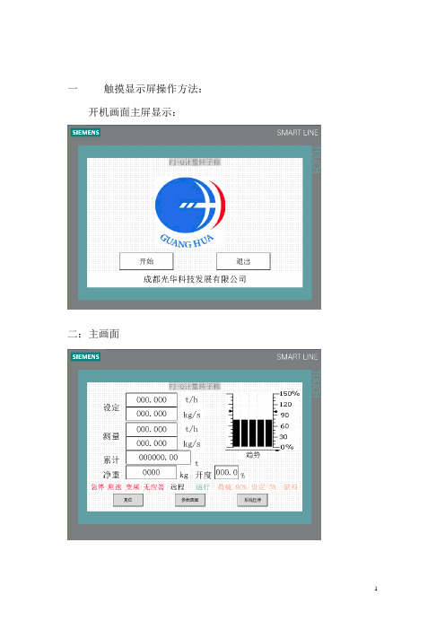
一触摸显示屏操作方法:开机画面主屏显示:二:主画面设定:设定流量(t/h)可根据产量更改。
测量:显视流量(t/h)。
累计:显示累计量(t)可以清零。
净重:称体荷载重量(kg)。
开度:流量阀开度显示(%)3个功能键分别是复位(当有故障时复位键显示)、参数画面(进入称参数调校修正)系统启停(在本柜的情况下启动此设备)三:功能选择画面(实现6不同功能分别进入相应的参数画面)四:功能画面1(参数设置)流量系数:标定称体系数根据现场标称结果而定。
DCS系数:修正中控室4~20mA给定信号。
停车延时:正常情况下转子称设有延时停车时间,将称体内物料转空。
最大流量:称体最大流量设定,与中控室相一致。
传感器量程:称传感器量程设定(kg)欠料:设定欠料量报警百分比。
欠料延迟:设定欠料后延迟报警的时间。
报警停车:在本柜控制的情况下报警后停车,中控制模式不停车权力交中控,当设为零时欠料不停车。
转速脉冲:设定测速脉冲最大数量(50Hz运行时)。
五:功能画面2(称体调校画面)功能键4个:除皮、皮重确认、系数确认、静态校秤1:校零点,设置除皮周期,按下除皮键,时间开始倒计时(秤体转整数周的时间),倒计时完皮重新值显示当前新皮重,按皮重确认键确认皮重新值为零点皮重。
2:校称:将变频器启动手动设定频率,设置校称周期(秤体转整数周的时间)按静态校称,校称倒计时开始,倒计时完校称累计显示累计量,将实测重量值输入按系数确认流量系数自动更改。
六:功能画面3(控制参数设定)1:秤设手自动2种模式:手动模式时频率由面板设定P1:称体调节比例系数(一般为:0.2)I1:称体调节几分系数(一般为:0.8)2:流量阀控制设手自动2种模式:手动时开度由面板设定设定2:设置称体装料能力(kg)净重2:显示称体装料量(kg)阀最大开度:阀门最大开度位限制(%)阀最小开度:阀门最小开度位限制(%)手动开度:设定阀门手动开度(%)P2:阀门调节比例系数(一般为:0.5)I2:阀门调节几分系数(一般为:0.3)D2:阀门调节微分系数(一般为:0.1)T2:时间常数,调节周期(一般为:2)开度:显示阀门测量开度七:功能画面4(数据画面)荷载数值:荷载工程值荷载:荷载用户值kg转速脉冲:速度传感器测量脉冲数荷载系数:此系数为偏载系数,出厂设定2.05 净重:称内(物料)荷载净重量。
GP用户手册

Pro-face GP承蒙使用日本Digital公司Pro-face GP系列触摸屏工业图形显示器产品,万分感谢。
在开始使用GP之前,请认真阅读本手册的有关说明。
本手册对GP产品的硬件特性、连接及初始化设定等内容作介绍。
警告:为了安全、正确地使用该装置,请遵守下列准则。
* 因为存在触电的危险,因此在连接电源线到GP上时,确保电源线没有接通电源。
* 由于GP内部装有高电压部件,当拆解该装置时,可能会引起触电,不要拆解GP。
* 不要使用超过电压范围的电源。
使用超过指定电压范围的电源,可能会损坏GP。
* 在有可燃性气体的环境中不要使用GP,否则可能引起爆炸。
* GP使用一个锂电池用来支持内部时钟数据。
如果错误的更换电池,可能引起爆炸。
为了避免危险,请不要自己更换电池。
当需要更换电池时,请与天任联系。
* 在涉及生命或有重大灾难的情况下,不要使用触摸屏键。
应使用单独的开关。
* 当GP与它的主控制器之间的通信出现错误时,请设计你的系统以便机器动作不会出现错误。
如果不这样,人有受到伤害的危险并且有可能损坏设备。
预防措施:* 不要用硬的或重物碰撞触摸屏,或用太大的力量按触摸屏,因为可能会导致无法修补的损伤。
* 如果放置GP的环境温度超出了规定的温度范围,GP将可能被损坏。
* 在GP的内部,不允许有水、液体或金属物质,否则会使GP损坏或触电。
* 避免减少GP的通风空间,或在易升温的环境中存放、使用GP。
* 避免在阳光直射、灰尘多、肮脏的环境中存放使用GP。
* GP是精密仪器。
注意不要对GP有大的冲击或振动,否则仪器容易损坏。
* 不要使用油漆,有机溶剂或强酸复合物擦拭显示器。
* 因为可能会有无法预料的事情发生,请对您的画面数据做备份。
GP系列触摸屏工业图形显示器用户手册目录第一章技术条件1.1一般规格 ---------------------------------------------------- 4 1.2功能特点 ---------------------------------------------------- 5 1.3GP各部分名称 ----------------------------------------------- 10 1.4外形尺寸 ---------------------------------------------------- 10 第二章安装与接线------------------------------------------------ 12第三章OFF-LINE(离线)方式3.1 进入OFF-LINE方式 ------------------------------------------- 15 3.2 主菜单 ---------------------------------------------------- 16 3.3 初始化—标准操作 -------------------------------------------- 16 3.4 自诊断—标准操作 -------------------------------------------- 16 3.5 画面数据传送 ---------------------------------------------- 17 第四章初始化4.1 初始化屏幕 ------------------------------------------------ 18 4.2 初始化项目 ------------------------------------------------ 18 4.3 系统环境设置 ---------------------------------------------- 19 4.4 I/O设置 -------------------------------------------------- 22 4.5 PLC设置 -------------------------------------------------- 26 4.6 初始化存储器 ---------------------------------------------- 29 4.7 时间设置 -------------------------------------------------- 30 4.8 屏幕设置 -------------------------------------------------- 30 第五章G P运行方式和出错信息5.1 进入运行(RUN)方式 ---------------------------------------- 31 5.2 问题解决 -------------------------------------------------- 31 5.3 自诊断 ---------------------------------------------------- 34 5.4 出错信息 -------------------------------------------------- 37第一章技术条件日本DIGITAL公司的Pro-face GP系列产品,目前有GP70和GP77两大系列。
天任tp-303t触摸屏说明书

天任tp-303t触摸屏说明书
天任tp-303t触摸屏说明书:
触摸屏硬件安装触挨屏是最直观的输入设备。
因为有了触摸屏,人们使用计算机象使用电视机一样简单。
本章介绍如何在显示器显像管上安装表面声波触摸屏。
在平面显示器上安装表面声波触摸屏的的过程与之相似。
触挨屏系统包括一张触摸屏、一个控制器、一根与PC通信的电缆线和驱动程序。
触摸屏
有各种尺寸配合不同大小显示器使用。
控制器也有各种类型,例如:串口、USB口等。
触摸屏的安装安装前的准备在试图安装触摸屏前,请通篇阅读本章内容,严格按照本章规定的程序操作。
安装前准备步骤:
注意安全警告和安装提示。
拆卸显示器是非常危险的过程。
安装前准备必要的设备。
建立一个舒适、宽敞的工作区。
好的工作区有助于安装成功。
测试显示器。
不要把触摸屏安装在非正常工作状态的显示器上。
注意:触摸屏屏体边缘的信号线保护在安装触摸显示器时,将触摸屏放入显示器外累内,将靠近屏体边缘的信号线位置的加强筋剪掉,并用电磨或拌刀将剪掉的位置打磨,以免将屏线判析。
触摸屏控制器用户手册说明书
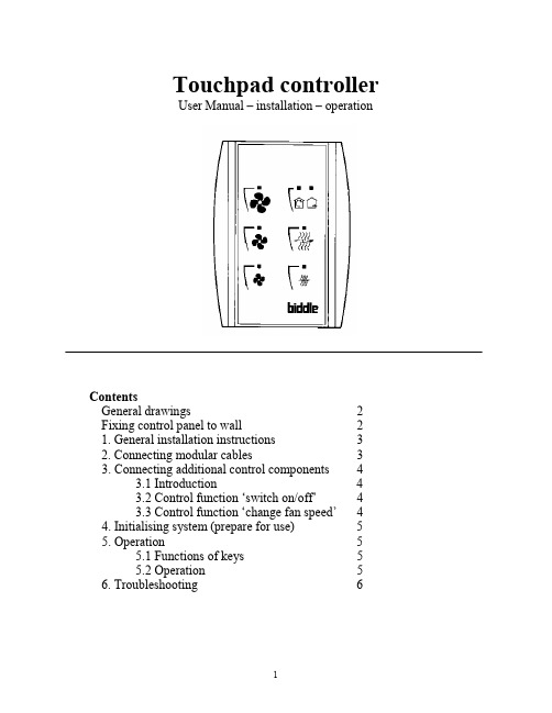
Touchpad controllerUser Manual – installation – operationContentsGeneral drawings2 Fixing control panel to wall21. General installation instructions32. Connecting modular cables33. Connecting additional control components43.1 Introduction43.2 Control function ‘switch on/off’43.3 Control function ‘change fan speed’44. Initialising system (prepare for use)55. Operation55.1 Functions of keys55.2 Operation56. Troubleshooting6Fixing control panel to wall 1234General drawings1. General installation instructions— Read this page carefully before starting the installation.— All installation work must be carried out by expert personnel.— Ensure that the appliances are disconnected from the mains before they are opened.— Avoid unnecessary contact with electronic components.Introduction:1. This manual is intended for all Biddle appliances with a built-in electronic interface.2. This manual describes the installation and use of the Biddle electronic control system.3. Several functions in this manual are only available from a certain version of a control system component. These functions are marked. Whenever you change an existing system you should compare the version number on the component with the version number in the manual.Installation details:1. Up to 10 appliances may be connected to one control panel.2. The total length of all modular cables in one system must be less than 100 metres.3. When installing the modular cable care should be taken to avoid interference with the cable by (electro)-magnetic fields as far as possible (therefore do not lay the cable close to high-voltage cables, fluorescent light starters, etc.)Components:The control system comprises the following components:1. Control panel consisting of 3, 4, 5 or 6 keys.2. Built-in interface with 3 or 6 output contacts, depending on the type of appliance.3. Modular cable including modular plugs, for connecting the control panel to one or more appliances. N.B.: B.T. type telecommunication cables are not suitable! The cable can be ordered from Biddle and is available in various lengths.Installation procedure:1. Connect modular cables + install control panel.2. Connect any customised controls, with control components with potential-free contacts.3. Provide all appliances with a power supply.4. Initialise the system.2. Connecting modular cablesA. Appliances with external connectionsType of appliance:— Modular fan coil unit (PS-B)— Air curtain (KW/MW/GW/KE/ME/GE/CAT/CAT-V)— Cassette air heater (KLV/KLV-E/KLVV)B.Appliances with internal connections Type of appliance:— Fan coil unit (B)— Extractor fan cabinetN.B.: The modular cables (X70) can be connected to both connectors (XiS)(see fold-out sheet, page 2).3. Connecting additional control componentsIf you have no control components to install, you can skip this section and go on to section 4 ‘Initialise the system’.3.1 IntroductionAs well as the basic system functions, there is also a possibility of connecting control components (e.g. room thermostat, timer BMS-controlled relay or door switch) to an appliance. Combinations of control components can also be used.N.B.: For remote switching on blocks X62/X72 volt free contacts are required. These contacts are advised to be gold plated and to have a low relay less than 20 m W to handle 1 mA at 5Vdc.Possible control functions:Control function Control range Adaptation to interface ofconnected appliance Connection points onblock X62/X72Connectionsummaryswitch on/off one appliance (local)none terminals T and G see § 3.2 switch on/off all appliances in system (general)remove jumper 6terminals T and G see § 3.2 change fan speed one appliance (local)none terminals D, P and G see § 3.3 change fan speed all appliances in system (general)remove jumper 5terminals D, P and G see § 3.3 N.B.: The function ‘switch on/off’ does not apply to the KLVV-unit. Consult the user manual of the unit when you want to connect control components to terminals T and G.3.2 Control function ‘switch on/off’1. Remove T-G bridge (X62/X72. see fold-out sheet, page 2) only from the appliance towhich the control component is to be connected.2. Connect the control component between T and G.— Contact made between T and G: Applicance stand-by.— No contact between T and G: Appliance/system off.3. General switching If the control function is to apply to the whole system, remove jumper 6(X64). This should only be done in the appliance to which the control component isconnected. Place the jumper on the reserve positions intended for it (X65), so that it can beused again later.3.3 Control function ‘change fan speed’1. Connect the control component between D and/or P and G (X62/X72, see fold-out sheet, page2). Important: do not disconnect T-G bridge.— Contact made between D and G : Appliance/system runs 1 speed higher than the controlpanel indicates (both speed and electric heating).— No contact between D and G Appliance/system working as indicated on the control panel.— Contact made between P and G Appliance/system runs at fan speed three (electric heatingstage remains unchanged, either one or two).— No contact between P and G Appliance/system working as indicated on the control panel.— Contact made between D, P and G: Appliance/system runs at fan speed three and electricheating stage two.N.B.: The functions using terminals P and G only are available from interface version V4.0Rev.06. Code IC 10 in the illustration on page 2 shows where you can find the version number.2. General switching: If the control function is to apply to the whole system, remove jumper 5(X64) as indicated in the facing illustration. This should only be applied to the appliance towhich the control component is connected. Place the jumper on the reserve positions intendedfor it (X65), so that it can be used again later.NB: General switching’ of the contact between P and G requires control pad version V2. IRev.02 or higher and interface version V4.O Rev.07 or higher. You can find the versionnumber on the printed circuit board of the control pad. In an existing system the control padcould be of a previous version. If the contact between P and G should still apply to the wholesystem, you should order a new control pad from Biddle.3. If the electric heating is not to be stepped up at the same time, remove jumper 4 (X64) asindicated in the illustration. This should be done in each appliance for which the function is required. Place the jumper on the reserve positions intended for it (X65), so that it can be used again later.14564. Initialising the system (prepare for use)When to use:1. On first installation.2. On each extension of the system.3. When checking cables.To start the procedure:1. Press keys 1, 2 and 3 simultaneously.—After 10 seconds the LEDs on keys 1 and 2 will start to flash. This flashing will continue for two minutes.— The LED on key 3 will then flash the same number of times as there are appliances in the system. The system is now ready for use.5. Operation5.1 Functions of keysLED lights when speed setting is ‘low’.LED flashes during initialisation.— Set speed to ‘low’.— Switch off appliance.— Start initialisation.LED lights when speed setting is ‘medium’LED flashes during initialisation.— Set speed to ‘medium’.— Switch off appliance.— Start initialisation.LED lights when speed setting is ‘high’.LED indicates number of appliances connected when initialisation is complete.— Set speed to ‘high’.— Switch off appliance.— Start initialisation.LED lights when electric heating is set to ‘low’.— Set electric heating to ‘low’.— Switch off electric heating.— Set electric heating to ‘low’ and speed to ‘low’.LED lights when electric heating is set to ‘high’.— Set electric heating to ‘high’.— Switch off electric heating— Set electric heating to ‘high’ and speed to ‘medium’.LED-R lights when setting is ‘Recirculate’ or standby.LED-V lights when setting is ‘Ventilate’.— Set air intake valve to ‘Ventilate’.— Set air intake valve to ‘Recirculate’.5.2 OperationA.Turn on appliance : Press key 1, 2, 3, 4 or 5.B.Turn off appliance : Press speed key (1, 2 or 3) on which the LED is illuminated. LED-R (if present) remains illuminated.Safety functions electric heating:1.The following scenarios will automatically be corrected:— Speed off, electric heating on.— Speed low, electric heating high.2. Appliance operates differently from control panel:If the appliance has just been switched off, it may start running again spontaneously.This is in order to discharge the heat stored in the heating elements.6.TroubleshootingAppliance not working:Check point Possible cause Action1no voltage on appliance check power supply to appliance2system not yet initialised start initialisation; see section 4 ‘Initialising the system’3poor contact in modular plug;check contacts (ensure plastic packaging is completely removed)4no bridge between terminals T and G fit bridge between terminals T and G on block X62/72. (see section 3‘Connecting Customised Control components’)5fuse(s) in appliance defective replace fuse (only to be done by skilled personnel)Appliance not working as expected:Check point Fault Possible cause Action/explanation1appliance (with electric heating)starts working spontaneously continued running of electricallyheated appliancesBiddle safety function; see section 5‘Operation’control components are notproperly connectedcheck system; see section 3‘Connecting Customised ControlComponents’2appliance works differently fromexpectationthe jumpers(l-3 red) on the interface are no longer in accordance with factory setting check jumper position against Specifications for factory setting jumper block X643electric heating not working appliance has overheated check maximum thermostat(see appliance manual) Factory setting jumper block X64Appliance type Jumper 1Jumper 2Jumper 3Jumper 4-6 appliance with electric heating with 2 positions present open present present CAT-air curtain open present present present KLV-E open present open present KLVV open open open presentall other appliances present present present present。
触摸屏使用说明书
1. 前言 (2)1.1 功能介绍 (2)1.2 技术指标 (3)1.3 注意事项 (3)2. 流水线操作指南 (4)2.1 启停控制 (4)2.2 故障复位操作 (6)2.2.1单工位故障复位 (6)2.2.2 断电故障复位 (7)2.3 屏蔽单工位操作 (9)2.4 单双线控制 (9)2.5 单独工位检测操作 (10)3. 触摸屏说明 (12)3.1 控制面板按钮说明 (12)3.2 触摸屏主页 (12)3.3辅助功能键 (14)3.3.1 辅助功能键F1 (14)3.3.2 辅助功能键F2 (15)3.3.3 辅助功能键F4 (16)3.3.4 辅助功能键F6 (18)4. 工控机说明 (19)4.1 打标机操作界面 (19)4.2 监控软件wincc (19)5.常见故障及处理 (19)5.1 单工位常见机械故障及处理 (19)5.2 报警处理 (20)5.3 电感式接近开关故障处理 (21)1. 前言1.1 功能介绍如上图所示为阀门检测流水线的平面视图,标有红色开始位置为阀门的手工上件处,也是整条流水线的起点。
本瓶阀检测流水线可以实现对瓶阀的流量、低压开启气密性、高压开启气密性、高压闭合气密性、外螺纹、内螺纹通规、内螺纹止规等的精确检测,同时对检测合格的产品进行压口和打标处理,对不合格的产品根据不合格的类型进行自动分拣。
上图中,气密性检测的A线和B线是功能相同的两条线,设置A、B线主要是为了提高检测效率。
阀门检测流水线分双线、A单线、B单线三种工作模式。
默认状态为双线运行模式,即A、B线同时运行,其检测的效率为36秒/个;A单线或B单线运行模式下,检测的效率均为72秒/个。
1.2 技术指标1.主控制柜输入电源电压AC380V,最大电流20A;控制柜内部弱电电压DC24V。
2.流水线正常工作气压:0.5~0.7Mpa;高压气密性检测的高压气体压力2.5MPa,低压检测的低压气体压力0.05Mpa。
触摸屏操作手册
恒温恒湿机组操作手册I n t e g r a t e d C o n t r o l S o l u t i o n s & E n e r g y S a v i n g s目录1主画面 (2)1.1界面说明 (2)1.2温度/湿度设定 (3)1.3图标说明 (3)2开/关机组 (4)2.1开机 (4)2.2关机 (4)3输入输出 (5)3.1数字量输入 (5)3.2模拟量输入 (5)3.3数字量输出 (6)3.4模拟量输出 (6)4参数设置 (7)4.1机组参数一览 (9)4.1.1控制参数 (9)4.1.2通用设置 (9)4.1.3限制功能 (10)4.1.4其他参数 (10)4.2定时设置 (11)4.2.1定时开关机 (11)4.2.2定时改设点 (11)4.2.3日期和时间 (12)5报警信息 (13)5.1当前报警 (13)5.2报警记录 (13)5.3导出报警记录 (14)6数据曲线 (15)6.1历史数据曲线 (15)6.2导出历史数据记录 (16)1主画面1.1界面说明触摸屏启动后,进入欢迎画面,5秒钟以后,自动跳到主画面:1.2温度/湿度设定✦点击主画面中的温度/湿度设值,可以调出键盘,直接输入设定值。
✦点击温度/湿度设值左边的“+”和“-”,可以直接增加或减少设定值”0.5”,以快速修改设定值。
1.3图标说明✦点击主画面左上角①所示位置,可以查看画面所有图标的描述点击画面左下角的“主页”按钮,返回主画面。
2开/关机组2.1开机机组停机时,点击主画面中的“开/关机”按钮,调出操作确认画面,点击“确认”执行开机操作,如果点击取消则返回主画面,不执行操作。
2.2关机✦机组开机时,点击主画面中的“开/关机”按钮,调出操作确认画面,点击“确认”执行关机操作,如果点击取消则返回主画面,不执行操作。
3输入输出✦点击主画面中的“输入/输出”按钮,查看控制器的输入/输出状态。
点击左侧导航栏,选择查看相应类别的状态。
天任文本连接手册
文本显示器通讯连接手册上海天任电子有限公司二00六年十二月目录1. 接口说明 (4)2. 下载电缆 (5)3. PLC连接 (6)3.1. 三菱(Mitsubishi)公司 (6)3.1.1. MITSUBISHI FX2N-CPU (6)3.1.2. MITSUBISHI FX2N-LINK (8)3.2. 西门子(SIEMENS)公司 (10)3.2.1. SIEMENS S7-200 PPI (10)3.3. 松下(NAIS)公司 (12)3.3.1. NAIS FP系列 (12)3.4. 欧姆龙(Omron)公司 (14)3.4.1. SYSMAC C系列 (14)3.5. 施耐德(Schneider)公司 (15)3.5.1. MODBUS (15)3.5.2. NEZA-MODBUS (15)3.5.3. TWIDO-MODBUS (17)3.6. 永宏(FATEK)公司 (18)3.6.1. FACON系列 (18)3.7. 光洋(Koyo)公司 (19)3.7.1. KOSTAC S系列 (19)3.8. 台达(DELTA)公司 (20)3.8.1. DVP系列 (20)3.9. LG公司 (21)3.9.1. Master-K系列 (21)3.10. KEYENCE 公司 (22)3.10.1. KV系列 (22)3.11. VIGOR 公司 (24)3.11.1. VH系列 (24)3.12. KDN 公司 (27)3.12.1. KDN-K3系列 (27)3.13. OEMAX公司 (28)3.13.1. NX系列 (28)3.14. Hitachi公司 (31)3.14.1. MICRO-EH系列(CPU系统软件版本在05××以上) (31)3.15. ASI公司 (34)3.15.1. ASIC/2系列 (34)4. 变频器连接 (37)4.1. ABB变频器 (37)4.2. 汇川MD变频器 (38)5. 伺服驱动器连接 (39)5.1. 力士乐伺服驱动器Ecodrive03/IndraDrive (39)6. 其他 (42)6.1. 演示DEMO (42)1.接口说明1.在COM1中有RS232和RS422/485的接口,但只能用其中的一个。
天任人机介面 TP100培训资料46页PPT

针型
Pin#
1 2 3 4 5 6 7 8 9
信号名
FG RXD TXD NMR GND NC NC NC VDD5
注释
框架地 接收数据 发送数据 复位输出 信号地 不连接 不连接 不连接 5V输出
容量规格
• FLASH、SRAM数据区容量:
型号 FLASH SRAM
106QB
3MB bytes
512K bytes
占两个寄存器,共32位,存放三级密码,可以用来查看修改三级密码。
二级密码 一级密码 当前数据输入的最大值 当前数据输入的最小值
占两个寄存器,共32位,存放二级密码,可以用来查看修改二级密码。 占两个寄存器,共32位,存放一级密码,可以用来查看修改一级密码。
键盘输入时,存放此时数据的最大值。 可以限制键盘输入数据的最大值 键盘输入时,存放此时数据的最小值。 可以限制键盘输入数据的最小值
字开关
• 描述:设置字开关的描述信息。 • 字地址:设置触摸字开关动作的字地
址。
• 字设置:触摸字开关,把常量中的值 写入指定的字地址。
• 加/减:触摸字开关,把字地址中的值 与常量进行相应的运算,并把结果存 储在字地址中。如果常量是一个正数, 执行加法运算;如果是一个负数,执 行减法运算。
• 位加1:触摸字开关,对字地址中值的 第N位(N:数字中指定的值)加1,并 把结果保存在字地址中,此加法为无 进位加法。
• 互锁有效:设置用于修改监视地址的值 的键盘的弹出时机。
• 操作密码控制:设置操作此部件的密码 级别。
• 触摸效果:设置触摸时的声音和显示效 果。
• 互锁监视地址/触发地址:控制键盘是否 弹出的位地址。
• 键盘窗口号:设置要弹出的键盘窗口号。
- 1、下载文档前请自行甄别文档内容的完整性,平台不提供额外的编辑、内容补充、找答案等附加服务。
- 2、"仅部分预览"的文档,不可在线预览部分如存在完整性等问题,可反馈申请退款(可完整预览的文档不适用该条件!)。
- 3、如文档侵犯您的权益,请联系客服反馈,我们会尽快为您处理(人工客服工作时间:9:00-18:30)。
1 软件的安装和运行环境1.1 概述1.2 系统组成1.3 软件运行的软,硬件环境1.4 软件的安装1.5 软件的卸载概述触摸屏工业图形显示器(简称触摸屏)是一种连接人类和机器(主要是PLC)的人机界面。
它是替代传统的控制面板和键盘的智能化操作显示器。
可以用于参数的设置、数据的显示和存储,以曲线和动画等形式描绘自动化控制的过程,并可以简化PLC的控制程序。
触摸屏的主要作用包括:1、监视:以数据、曲线、图形、动画等各种形式来反映PLC的内部状态及存储器数据,从而直观地反映工业控制系统的流程、走向。
2、控制:可以通过触摸来改变PLC内部状态位、存储器数值来参与过程控制。
3、数据处理:通过标准的大容量CF卡、U盘存储实时采样数据和历史报警信息。
返回上一级系统组成软件系统由工程管理器、工程传送和工程模拟三部分组成,其中,工程管理器内嵌画面开发系统。
工程管理器、Transfer和SimPLC 是各自独立的Windows应用程序,均可单独使用;三者又相互依存,在工程管理器的画面开发系统中设计开发的画面应用程序必须通过Transfer下载到触摸屏上运行;下载到触摸屏后可以利用SimPLC模拟PLC与触摸屏进行通讯,以便调试画面程序。
参见工程管理器、工程传送、工程模拟。
返回上一级软件运行的软硬件环境u硬件:奔腾PIII 500以上IBM PC 或兼容机u内存:最少64MB,推荐128MBu显示器:VGA、SVGA或支持桌面操作系统的任何图形适配器。
要求最少显示256色。
u鼠标:任何PC兼容鼠标u通讯:RS-232Cu操作系统:Win2000/Win XP简体中文版返回上一级软件安装返回上一级软件的卸载返回上一级2 软件的使用入门2.1 Windows相关基本操2.2 工程管理器2.2.1 工程管理器的主要界面说明2.2.2 主菜单用途简要说明2.3 软件的使用2.3.1 启动软件2.3.2 新建/打开/保存工程2.3.3 新建/打开/保存画面2.3.4 退出系统2.4 如何获取帮助Windows相关基本操作鼠标的基本操作键盘的基本操作窗口的组成与操作◆鼠标的基本操作1)指向:把鼠标光标移动到某一个对象上。
2)单击:将鼠标光标指向一个对象后,按下并快速松开左键,称为单击。
3)双击:鼠标光标指向一个对角后,连续两次快速按下并快速松开鼠标按键的操作,称为双击。
4)拖放:选中需报拖动对象后,按住鼠标按键不松开并移动鼠标,移动时屏幕上鼠标所选定的对象将随之移动,到达目标位置后,松开鼠标按键即可将所选中的对象移动到指定位置上,这个操作叫拖放。
5)右击:单击鼠标右键。
返回◆键盘的基本操作键盘操作可以分为输入操作与命令操作两种方式。
1)输入操作以向计算机输入信息为主要目的,用户可以通过键盘向计算机输入英文字母、汉字、数字及各种符号。
2)命令操作的目的是通过向计算机发布一个命令,让计算机完成相应工作。
命令操作通过特定的键或几个键的组合来表示一个命令,这些键通常被称为快捷键。
返回◆窗口的组成与操作1)窗口组成:下图为所示的“我的电脑”窗口是一个典型的Windows文件窗口,其中包括标题栏、菜单栏、工具栏、状态栏及工作区域等。
2)窗口的操作:a)移动窗口:将鼠标光标移到窗口的标题栏上,按下鼠标左键并拖动鼠标即可。
b)改变窗口尺寸:将鼠标移动到窗口的边框或四个顶角上,此时光标改变成双箭头形状,按下左键并拖动鼠标即可。
c)最小化、最大化/还原、关闭窗口:分别单击窗口上最小化、最大化/还原、关闭按钮即可。
d)切换窗口:用鼠标单击任务栏上对应窗口的按钮即可。
返回返回上一级2.2.工程管理器2.2.1主菜单用途简要说明2.2.2工程管理器的主要界面说明返回上一级主菜单用途简要说明主菜单包括:工程与文件、编辑、查看、绘图、部件、特殊、图库、工具、窗口、帮助。
各部分功能如下:返回返回Page 5 of 120返回返回返回返回返回返回返回返回返回返回上一级工程管理器主要界面说明工程管理器主要由菜单、工具栏、工程浏览器、画面编辑窗口、信息窗口、状态栏组成。
具体如下:菜单包括对工程中画面、图元的操作,具体内容参见主菜单用途简要说明。
工具栏包括:工具栏、绘图工具栏、部件工具栏、栅格工具栏、标记工具栏、多语言表工具栏、编辑工具栏、状态工具栏。
工具栏:可进行新建工程、打开工程、保存工程、新建画面、打开画面、保存画面、打开下载界面、工程仿真、缩小画面、放大画面、打印画面、打开版本信息、打开帮助文件及退出操作。
绘图工具栏:可进行选择、点、直线、矩形、多义线、多边形、椭圆(圆)、弧、饼、直线刻度、圆弧刻度、文本、画面加载、图象加载、虚拟对象、从图库载入、保存至图库操作。
部件工具栏:可进行位开关、字开关、功能开关、乒乓开关、指示灯、棒图、饼图、半饼图、水槽图、指针仪表、数据指示器、信息显示器、日期显示器、时间指示器、趋势图、报警显示器、数据记录显示器、文本显示器、数据配方显示器操作。
栅格工具栏:可选择栅格大小、栅格是否显示、栅格是否停靠操作。
标记工具栏:可选择图元ID和图元地址是否显示操作。
多语言表工具栏:当使用多语言功能时,可选择切换当前画面显示的语言类型。
编辑工具栏:可进行撤消、重新执行、剪切、复制、粘贴、删除、对齐、左旋转90°、右旋转90°、X轴镜像、Y轴镜像、左对齐、垂直中心对齐、右对齐、上对齐、水平中心对齐、下对齐、组合、组解散、置前、置后、图形前项、图形后项、图形属性、动画连接、刷新画面操作。
状态工具栏:可显示当前画面部件为OFF、ON、第2种、第3种……第15种时的状态。
画面编辑窗口是工程管理器的主要编辑工作部分,用于编辑画面。
工程浏览器主要用于显示当前工程所在的目录,并可在所选择的目录下单标鼠标右键,进行弹出新建工程、打开文件夹操作。
信息窗口主要用于显示当前工程中画面信息。
状态栏用于实时显示鼠标位置、画面占用空间大小、当前工程连接的PLC类型及当前画面编辑窗口的缩放信息。
返回上一级2.3 软件的使用2.3.1 启动软件2.3.2 新建/打开/保存工程2.3.3 新建/打开/保存画面2.3.4 退出系统返回上一级启动软件返回上一级新建打开保存工程新建工程打开工程保存工程新建工程选择“工程与文件”菜单项中的“新工程...”或者在工程浏览器中所选择的文件夹上单击鼠标右键,选择“新工程...”弹出新建工程对话框:对话框中各参数的含义如下:基本信息工程文件位置:指定新建工程在计算机里存放的位置。
通过单击“浏览”按钮,从弹出的“浏览文件夹”对话框中选择工程路径。
默认为上次新建工程所在位置。
文件名:指定新建工程的工程名;默认为“新工程N”,N随着工程的个数的变化而变化。
例如:新工程、新工程1、新工程2 ……备注:对新建工程的描述信息。
无默认内容。
触摸屏信息产品系列:选择所用产品的型号所属的系列。
型号:选择所用产品的具体型号,软件与硬件上型号需一致。
显示方向:选择所用产品的安装方式。
信息:显示所选产品的屏幕分辨率及颜色信息。
PLC信息COM1-PLC:选择通讯口1(COM1口)所连的PLC的型号。
单击“浏览”弹出COM1所支持的PLC厂家,如下图,选择相应的PLC协议即可。
单击“确定”按钮,保存所选择的PLC型号;单击“取消”按钮,退出“PLC型号”对话框。
COM2-PLC:选择通讯口2(COM2口)所连的PLC的型号。
单击“浏览”弹出COM2所支持的PLC厂家,如下图,选择相应的PLC协议即可。
单击“确定”按钮,保存所选择的PLC型号;单击“取消”按钮,退出“PLC型号”对话框。
注:两通讯口可选同一厂家同一型号的PLC,也可选不同厂家不同型号的PLC,也可只用其中一个通讯口,根据实际情况具体对待。
返回打开工程选择“工程与文件”菜单项下的“打开工程...”弹出“打开”对话框:在对话框中选择要打开的工程,单击“打开”按扭,打开相应的工程。
或者也可以在工程浏览器中选择要打开的工程,单击鼠标右键,选择“打开工程”。
甚至可以直接双击工程浏览器中的工程,都可以打开相应的工程。
返回保存工程选择“工程与文件”菜单下“保存工程”项,保存当前活动的工程。
也可以在工程浏览器中,在当前活动工程处单击鼠标右键,选择“保存工程”,完成此操作。
返回新建打开保存画面新建画面打开画面保存画面新建画面选择“工程与文件”菜单下的“新画面...”或者单击工具栏中按钮,或者在工程浏览器中当前工程的目录下,在相应的画面类型上,单击鼠标右键,选择“新画面...”或者按下快捷键“CTRL+N ”弹出“新建画面”对话框对话框中各参数的含义如下:画面类型:从列表中选择新建画面的类型。
窗口风格:选择画面背景风格。
前景色:选择画面风格对应的前景色。
背景色:选择画面风格对应的背景色。
设置好画面的各属性后,单击“确定”,保存当前信息,完成新建了一空画面。
返回打开画面选择“工程与文件”菜单下的“打开画面...”或者单击工具栏中按钮,或者按下快捷键“CTRL+O ”快捷键,弹出“打开画面”对话框Page 11 of 120对话框中各参数的含义如下:画面类型:从下拉菜单中选择要打开的画面的类型画面列表:列出当前工程中的所选的画面类型下的所有画面及其描述信息,可通过双击直接打开选中的画面,或者选中它,再按“打开”按钮。
或者还可以在工程浏览器中选择工程目录下的画面类型后,在信息窗口中双击要打开的画面直接打开。
返回保存画面选择“工程与文件”菜单下的“保存画面...”或者单击工具栏中按钮,或者按下快捷键“CTRL+S”快捷键,保存当前活动的画面。
返回返回上一级退出系统选择“工程与文件”菜单下“退出”,或者单击软件右上角的按钮。
如果此时,当前正在编辑的工程存在没有保存的画面,系统会弹出提示单击“是”按钮,保存画面,并退出系统。
单击“否”按钮,不保存,退出系统。
单击“取消”按钮,取消当前操作,回到正在编辑的工程。
返回上一级如何获取帮助在“帮助”菜单下选择“帮助主题”,或者直接按下键盘的F1键,弹出“系统帮助”。
在“帮助”菜单下选择“设备助手1”或“设备助手2”,弹出当前工程连接的PLC1或PLC2的帮助信息。
在软件使用过程中,单击对话框中“帮助”按钮,查看该对话框对应的帮助信息。
返回上一级3 工程与画面、操作规范3.1 分类:画面3.2 分类:图元、部件、特殊部件与特殊功能3.3 规范:PLC 地址数据的输入,必读!3.3.1 规范的地址格式3.3.2 变量及其使用3.4 规范:数据格式的定义,必读!分类:画面工程由一个个画面组成,在HMI 处于运行方式期间,显示的是基本画面,在基本画面中可以调用其它画面,组合利用各种画面,完成复杂的功能并在HMI 上显示。
