atmel ASF学习笔记
Atmel软件框架ASF-3.40文档说明书

The Atmel® Software Framework (ASF, /asf) is a compilation of embedded software for Atmel flash MCUs: megaAVR®, AVR XMEGA®, AVR UC3 and SAM devices. It has been designed to help develop and glue together the different components of a software design. It can easily integrate into an operating system (OS) or run as a stand-alone product.
• Added SAM D20 Services (GFX_mono, Delay, Dataflash, FreeRTOS) • Added SAM D20 applications (DAC sound player, SPI/I2C bootloader, Led toggle d OSC8 calibration,
Installation Instructions
Device Support
This release supports the following devices:
• AVR UC3 • AVR UC3 A0/A1 (revision H and later) • AVR UC3 A3/A4 (revision E and later) • AVR UC3 A3xS/A4xS (revision E and later) • AVR UC3 B (revision F and later) • AVR UC3 C (revision D and later) • AVR UC3 D • AVR UC3 L
《Robot Framework 自动化测试框架核心指南》读书笔记模板

口自动化测试
5 第4章移动手机
自动化测试
第5章 Web自动化测 试
第6章编写自定义的 Robot Framework
Lib
第7章自动化测试用 例的编写技巧
第8章自动化测试框 架的设计
1.1如何创建一个自动化测试项目 1.2 Robot Framework基础关键字 1.3 Robot Framework断言关键字 1.4 BuiltIn库剩余关键字
6.1使用Python编写自定义的Robot Framework Lib 6.2使用Java编写自定义的Robot Framework Lib
7.1自动化测试用例的常用技巧 7.2如何高效地维护好自动化测试用例
8.1 Jenkins下自动化测试的调度管理 8.2如何做好自动化测试平台框架的设计 8.3其他常用的自动化测试框架介绍
读书笔记
基本上就是对摘抄翻译rf官方和rf插件的文档.可以留着参考,但是价值不大.。
快速浏览了一遍书籍内容,主要内容基于robotframework ride客户端,较详细罗列了各个步骤和界面,内 容比较浅显。
目录分析
1
内容简介
第1章初识
2
Robot
Framework
3 第2章 Robot
Framework对 数据库的操作
精彩摘录
这是《Robot Framework 自动化测试框架核心指南》的读书笔记模板,可以替换为自己的精彩内容摘录。
作者介绍
这是《Robot Framework 自动化测试框架核心指南》的读书笔记模板,暂无该书作者的介绍。
谢谢观看
Robot Framework 自动化测试框 架核心指南
读书笔记模板
Stata学习笔记之欧阳家百创编
以下命令均采用小写字母欧阳家百(2021.03.07)Chapter 1 stata入门1.1打开数据use "D:\Stata9\auto.dta", clear 用use命令打开数据sysuse auto,clear auto 为系统数据 sysuse为打开系统数据的命令1.2获取帮助Help summarize summarize为需要获取帮助对象可以改为其他的需要帮助的对象Findit summarize,net寻找网络帮助summarize为需要获取帮助对象Search summarize ,net 寻找网络帮助summarize为需要获取帮助对象显示结果Display 5+91.3描述统计(summarize 可简写成sum)Use atuo,clearSummarize price 描述price的观察值个数、平均值、标准差、最小值、最大值Sum weight summarize可简写成sumSum weight price 同时完成上面两步1.4绘图Scatter price weight scatter 为绘制散点图命令Line price weight ,sort line 为绘制折线图命令,sort为排序,绘制折线图前需要先排序1.5生成新的数据(generate 可简写成gen)ClearSet obs 1000 设置观测值的组数Gen x=_n _n 为观察值得序号Gen y=x+1001.6控制结果输出显示List n1.7设置屏幕滚动Set more off 先设置此项则显示时,屏幕不停止Set more on 先设置此项则显示时,会使显示停止1.8清除内存中原有内容clear1.9设置文件存取路径(cd)Cd d:\stata d:\stata为路径1.10如果想知道当前路径下有哪些文件,可以用dir 命令来列示.dir1.11假设你想在D 盘的根目录下创建一个新的文件夹mydata 来存放数据文件,命令为mkdir。
asf库函数
asf库函数ASF(Advanced Software Framework)库是微芯片公司所提供的开发工具,在各种微芯片上用C语言进行开发,提供丰富的应用程序接口(API),并能适配不同硬件平台。
ASF库是针对微芯片进行开发的,能够极大的提高开发效率和降低开发难度,成为目前非常流行的嵌入式开发工具。
ASF库中包含了大量的API函数,这些函数都是针对于各种不同的应用场景所提供的。
下面我们来一步步的了解ASF库函数。
1. ASF库函数概述ASF库函数提供了许多可重复使用的现成功能,这些功能包括文件系统、串口通信、网络协议栈、USB接口等等。
这些功能函数封装成API函数,可以方便地在C语言程序中调用。
ASF库可在开发板上运行,并且不需要与特定的操作系统或文件系统配合使用。
2. ASF库函数的使用ASF库函数可以在各种开发工具中使用,并提供了相应的示例代码。
开发者可以通过调用ASF库函数来完成各种应用,而不必学习芯片寄存器和底层驱动等知识。
在使用ASF库函数时,需要先初始化相应的设备和系统,这有利于保证各种设备和系统的正常运行。
3. ASF库函数的优点ASF库函数提供了许多可重用的现成功能,这让开发者可以更加专注于应用程序的开发上。
通过使用ASF库函数,可以降低开发难度和提高开发效率。
同时,ASF库函数充分利用微芯片提供的硬件资源,以达到最佳的性能和功率消耗比。
4. ASF库函数的应用场景ASF库函数广泛应用于嵌入式系统中,包括传感器、控制器、网关等应用。
它还广泛应用于医疗设备、智能家居、工业自动化等领域。
通过使用ASF库函数,开发者可以用更少的代码和时间来实现各种应用。
总之,ASF库函数是嵌入式系统开发的好帮手,它提供了许多可重用的现成功能,可以降低开发难度和提高开发效率。
如果您是嵌入式开发人员,ASF库函数一定是您的最佳选择。
atsam asf手册

atsam asf手册
ATSAM和ASF分别指的是Atmel的ARM-based处理器系列和Atmel Software Framework。
ATSAM系列是Atmel的ARM处理器系列,包括ATSAM3、ATSAM4、ATSAMD和ATSAME等系列,这些处理器
广泛应用于嵌入式系统中。
ASF是Atmel提供的一套软件框架,用
于简化嵌入式应用程序的开发。
ASF提供了丰富的库函数、示例代
码和工具,帮助开发人员快速开发嵌入式应用程序。
对于ATSAM和ASF的手册,你可以在Atmel官方网站上找到相
关的技术文档和手册。
这些手册包括处理器的数据手册、参考手册、用户指南等,以及ASF的文档和API参考手册。
在这些手册中,你
可以找到关于处理器架构、外设功能、寄存器编程、软件框架的详
细信息,以及示例代码和开发工具的介绍。
此外,你还可以在社区论坛、技术博客和开发者社区中寻求帮
助和资源,这些地方经常有开发者分享关于ATSAM和ASF的经验和
技术讨论。
总之,要深入了解ATSAM和ASF,建议你首先查阅官方的技术
文档和手册,然后结合社区资源和实际开发经验,逐步掌握这些技
术的应用和开发技巧。
希望这些信息能够帮助到你,如果有更多问题,欢迎继续向我提问。
基于ASF的Atmel Studio 7.0使用方法介绍
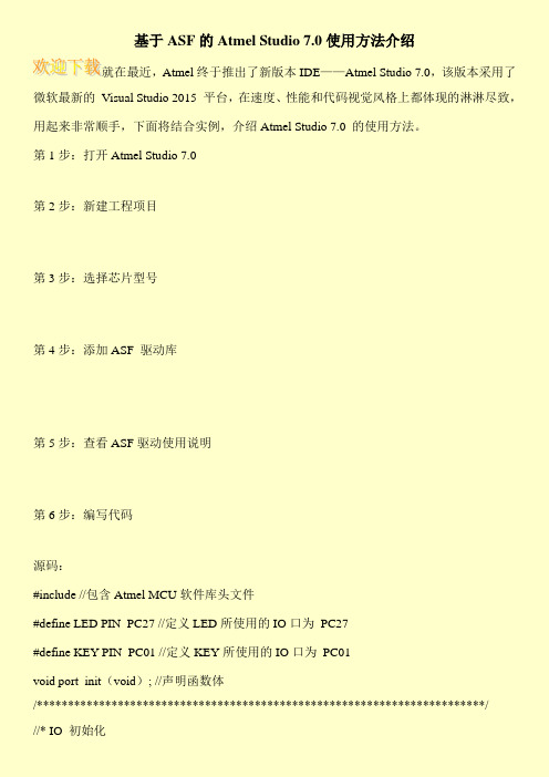
第2步:新建工程项目
第3步:选择芯片型号
第4步:添加ASF驱动库
第5步:查看ASF驱动使用说明
第6步:编写代码
源码:
#include //包含Atmel MCU软件库头文件
#define LED PIN_PC27 //定义LED所使用的IO口为PC27
#define KEY PIN_PC01 //定义KEY所使用的IO口为PC01
void port_init(void)
{
struct port_config config_port_pin;
port_get_config_defaults(
config_port_pin.direction = PORT_PIN_DIR_OUTPUT; //配置IO口方向为输出
port_pin_set_config(LED,//初始化LED对应IO口
{
port_pin_set_output_level(LED,0);
}
else
{
port_pin_set_output_level(LED,1);
}
}
}
第7步:编译并生产烧录文件
第8步:烧录文件到开发板
int main(void)
{
system_init(); //系统初始化
/* Insert application code here,after the board has been initialized. */
port_init(); //IO初始化
while(1)
{
if(port_pin_get_input_level(KEY)== 0)//KEY按下,LED对应IO电平= 0
briefacse记忆方法

briefacse记忆方法
一、简介
Briefcase记忆方法是一种把大量复杂的信息整合在一个口袋上的记忆形式。
它可以帮助学习者快速地理解、记住、分析、应用复杂的信息,而这些信息可以是文学、历史、科学方面的知识,也可以是任何能够在多个方面进行整理和研究的知识,比如分析案例中的多方视角。
二、过程
1、准备:准备一个实体口袋,或者是一个形象口袋,口袋是存放信息的地方。
2、整理:把所有的信息和知识按照一定的规律整理到口袋里,口袋的内部由若干个口袋分隔,每个口袋用一个具体的主题或概念来标示。
3、体验:学习者在学习过程中,用一种联想的方式,把信息和知识分别放入每一个口袋,并用一种自己的体验方式来实现。
4、回忆:通过口袋,学习者可以快速地回忆所学的知识,有助于更好地复习和理解,也可以更好地应用到实际情况中。
三、优点
1、更快的学习和记忆:Briefcase记忆方法给学习者提供了一个更快学习和记忆信息的办法,可以有效地提高学习效率,节省学习时间。
2、创新分析:口袋中的口袋可以帮助学习者进行创新的分析,
从而更好地理解复杂的知识。
3、强大的应用:Briefcase记忆法可以帮助学习者快速地把知识应用到实际情况中,可以有效地提高学习者的实践能力。
四、缺点
1、时间紧迫:Briefcase记忆法让学习者把大量复杂的信息在较短的时间内完成记忆,如果处理不当,可能会影响学习者的学习效果。
2、费事:Briefcase记忆法的过程比较繁琐,把大量信息整理到口袋中需要学习者付出一定的时间和精力,这可能会影响学习者的学习效率。
麦肯锡方法读书笔记

《麦肯锡学习方法》精华内容提炼同事推荐《麦肯锡学习方法》,看后受益匪浅,为此还特意追订了本书推荐Gene Zelazny的《用图表说话》。
本书由于重要价值信息太多,无法用一篇简短的感想概括。
于是从头把书中的重要信息摘录出来,与大家共享——Alfredx。
第一章建立解决方案1 以事实为基础2 系统化的MECE(me see)原则: 相互独立、完全穷尽。
解决商业问题时,要形成自己的观点,解题思路必须在保持其完整性的同时避免混淆和重叠。
3大胆假设、小心求证:解决一个复杂问题如同开始一段长途旅行,初始假设是你的问题解决路线图。
生成初始假设的方法:1)寻找公司里该领域的行家,这是追上行业最新动向最为快捷、最为有效的方法。
2)将问题拆分,发现关键驱动因素。
建立建议树。
第二章探索分析问题的方法方法:以事实为基础的,系统化的,大胆假设,小心求证1 利用前辈的经验,不要做重复劳动。
2咨询顾问可以转而将解决问题的重点置于“关键驱动因素”。
3 假设求证1)用以事实为基础的分析方法让你的初始假设(或你的直觉)生效,这更有利于别人接受你的观点。
纵然你的直觉反应也许(很可能)是对的,那也要花时间通过事实来验证。
2)麦肯锡使用以事实为基础的分析方法,在为客户提出建议之前都需要进行严格的论证。
4 不要寻找事实去支撑你的提案你的思想要保持开放与灵活,不要让强有力的初始假设成为思想僵化的接口。
不论你觉得自己的初始建设多么精彩绝伦、解决深刻、新颖独特,你都必须时刻准备接受证明你错误的事实。
假如事实证明你的初始假设是错误的,那就根据事实做出调整。
不要将事实捣碎硬塞进你的结构框架。
5 确保解决方案适合你的客户要了解你的客户,了解这个组织的优势、劣势及能力——管理层做得到的事和做不到的事。
牢记你的解决方案要与这几个要素相符。
了解这些局限后,你就得确保提出的任何建议都在客户力所能及的范围。
而麦肯锡人(尤其是新入职的员工)的第一反应是竭力追求最佳的解决方案。
Atmel_Studio_6.1_简易使用教程
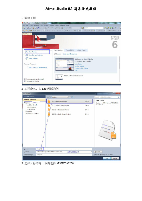
Atmel Studio 6.1简易使用教程 1 新建工程2 工程命名,以LED闪烁为例3 选择目标芯片,本例选择AT32UC3A02564 工程创建完成,在生成的main函数里编写相应代码5 Atmel Software Framework(简称ASF)为不同的MCU提供软件驱动和库来加快开发过程,ASF的架构如下图Your application对应要实现的软件应用Utilities对应开发工具和宏Boards对应开发板或者用户自定义板ASF由Drivers、Components和Services三部分组成:①Drivers对应片上设备的驱动,如ADC、FLASH、GPIO、INTC、PM、PWM、USART等②Components对应外设驱动,如存储器、显示屏、传感器等③Services对应FAT文件系统、DSP库、USB等6 导入ASF。
进行开发时,借用官方提供的驱动,可以大大简化开发进程在此添加Drivers/GPIO点击Apply将选择的模块添加到工程中7 此时编译发现报错双击错误进入错误位置查看Output,发现问题出在编译startup_uc3.S 文件时出现重复定义错误问题的原因在于:startup_uc3.S 文件是Atmel 官方自定义的启动文件,并非标准启动文件(crt0.o,指定main 函数的入口地址),在工程属性里应该设置不使用标准启动文件,否则就会出现重复定义的错误。
解决:在工程目录中右键选择工程属性再次编译,成功通过_start 和_stext 在startup_uc3.S 文件中重复定义,第一次定义在crt0.o 文件中8 在main函数中编写相应代码,实现LED闪烁控制。
9 编译通过后,将生成的.hex或.elf烧写文件下载到flash中看运行结果。
斯坦福 nlp课程笔记

斯坦福 nlp课程笔记斯坦福NLP课程笔记斯坦福大学自然语言处理(NLP)课程是一门涵盖了自然语言处理领域广泛知识的课程。
本篇笔记将对该课程的核心概念和重要内容进行总结和讨论。
以下是我对该课程的学习心得和笔记。
1. 自然语言处理简介自然语言处理是计算机科学与人工智能领域的重要研究方向,涉及处理和理解人类语言的算法和技术。
它包括了文本处理、语音处理、语义理解等方面的内容。
2. 语言模型语言模型是自然语言处理的基础,它可以用来估计或产生自然语言句子的概率。
常见的语言模型包括n-gram模型和神经网络语言模型。
3. 词向量表示词向量表示是NLP中常用的技术,可以将词语映射到一个低维向量空间中,从而捕捉到词语之间的语义关系。
Word2Vec和GloVe是两种常见的词向量表示方法。
4. 序列标注序列标注是将输入的序列与特定的标签进行关联的任务,常见的序列标注任务包括命名实体识别和词性标注。
隐马尔可夫模型(HMM)和条件随机场(CRF)是序列标注中常用的算法。
5. 语义角色标注语义角色标注是指对于一个给定的句子,通过识别出该句子中的动词和名词短语,并为它们分配语义角色标签。
语义角色标注可以帮助理解句子的结构和语义。
6. 语义解析与语法分析语义解析是指将自然语言句子转化为语义表示的过程,常见的语义解析方法包括基于规则的方法和基于统计的方法。
语法分析则是将句子结构化成一种形式化的表示,常见的语法分析方法包括依存句法分析和成分句法分析。
7. 机器翻译机器翻译是将一种自然语言转化为另一种自然语言的任务,机器翻译也是自然语言处理中的重要应用之一。
统计机器翻译和神经网络机器翻译是当前主流的翻译方法。
8. 文本生成文本生成是指通过算法和模型生成符合语法和语义规则的自然语言文本,常见的文本生成任务包括文本摘要和对话生成。
9. 情感分析情感分析是指识别和推测出文本中的情感倾向和情感状态,常见的情感分析任务包括情感分类和情感强度预测。
atsam asf手册
atsam asf手册
ATSAM和ASF都是与Atmel(现在是Microchip)微控制器相关的术语。
ATSAM是Atmel的一系列ARM Cortex-M基于微控制器的产品线,而ASF代表Atmel软件框架,是Atmel提供的用于编程Atmel微控制器的软件库和工具集。
关于ATSAM和ASF的手册,你可以在Microchip官方网站上找到相关的文档和手册。
这些手册通常包括了对ATSAM微控制器的硬件描述、引脚定义、寄存器配置、外设控制等方面的详细说明。
同时,ASF的手册则会涵盖ASF软件框架的使用方法、API参考、示例代码等内容。
在阅读ATSAM和ASF手册时,你可以从不同的角度进行深入的学习和理解。
首先,可以从硬件角度深入了解ATSAM微控制器的架构、外设功能、时钟和电源管理等方面。
其次,可以从软件角度学习ASF框架的使用方法、库函数的调用、驱动程序的开发等内容。
此外,还可以从应用角度考虑,了解在实际项目中如何利用ATSAM 微控制器和ASF框架来实现特定的功能和应用。
总之,通过深入研读ATSAM和ASF的手册,你可以全面地了解
这些产品的特性和功能,为你在微控制器编程和应用开发中提供丰富的知识和技能支持。
希望这些信息能够帮助到你,如果你需要更多的帮助,请随时告诉我。
Atmel SAM D09 D10 D11 ARM Cortex-M0+ 基于的微控制器入门指南说明

SMART ARM-based Microcontrollers AT06467: Getting started with SAM D09/D10/D11APPLICATION NOTEFeatures•Getting started with Atmel® | SMART SAM D09/D10/D11microcontrollers and tools•Getting started with SAM D11 Xplained PRO, SAM D10 Xplained Mini, and Atmel Studio 6.2DescriptionThis application note helps the readers to get started with the Atmel SAMD09/D10/D11 ARM® Cortex®-M0+ based microcontroller.Table of Contents Features (1)Description (1)1.Getting the Device Datasheet (3)2.SAM D Evaluation Platform (4)2.1.SAM D11 Xplained Pro (4)2.2.SAM D10 Xplained Mini (5)2.3.SAM D09 On-board (7)3.Get the Tools (8)3.1.Get Atmel Studio 6.2 (8)3.2.Get IAR Embedded Workbench for ARM (8)3.3.Get Atmel Software Framework (ASF) (8)4.Atmel Studio 6.2 Users Getting Started (9)4.1.Getting Started with SAM D11 Xplained Pro (9)4.2.Getting Started with SAM D10 Xplained Mini (10)4.3.Getting Started with SAM D09 (12)5.What’s next? (15)6.Revision History (16)1. Getting the Device DatasheetWeb page:/products/microcontrollers/arm/sam-d.aspx?tab=overview•Document: Atmel SAM D11 Datasheet (summary, complete) (.pdf)•Document: Atmel SAM D10 Datasheet (summary, complete) (.pdf)•Document: Atmel SAM D09 Datasheet (summary, complete) (.pdf)•Select the required device (e.g. ATSAMD11D14A) and get the latest datasheet (.pdf file)•Two versions of the datasheet are available:–Complete version (includes all peripheral descriptions and electrical characteristics)–Summary version (includes ordering information, pinout, and packaging information)2. SAM D Evaluation PlatformThe following development boards are available for evaluation of SAM D11/D10 devices:1.SAM D11 Xplained Pro.2.SAM D10 Xplained Mini.2.1. SAM D11 Xplained ProThe Atmel SAM D11 Xplained Pro evaluation kit is a hardware platform to evaluate the ATSAMD11D14A MCU. Supported by the Atmel Studio integrated development platform, the kit provides easy access tothe features of the Atmel ATSAMD11D14A and explains the steps to integrate the device in a customdesign.The Xplained Pro MCU series evaluation kits include an on-board Embedded Debugger. No external tools are required to program or debug the ATSAMD11D14A.The Xplained Pro extension kits offers additional peripherals to extend the features of the board and ease the development of custom designs.Figure 2-1 SAMD11 Xplained ProWeb page:/products/microcontrollers/arm/sam-d.aspx?tab=toolsGet the kit:/buy/Document/file:•Atmel-42349-SAMD11-Xplained-Pro_User-Guide.pdfKey features:•SAMD11D14A microcontroller•One mechanical reset button•One mechanical programmable button (SW0)•One yellow user LED (LED0)•USB device interface function•Two QTouch buttons•32.768kHz crystal•Standard Cortex Debug connector•One Xplained Pro extension headers (EXT1)•USB powered•Supported with application examples in Atmel Software Framework•Embedded Debugger•–Auto ID for board identification in Atmel Studio 6.2 or later–One yellow status LED–One green board power LED–Symbolic debug of complex data types including scope information–Programming–Data Gateway Interface: USART, TWI, four GPIOs–Virtual COM port (CDC)The SAM D11 Xplained Pro User Guide application note covers the instructions to power the kit, thedetailed information of the on board components, extension interface and the hardware guide.2.2. SAM D10 Xplained MiniThe ATSAMD10 Xplained Mini evaluation kit is a hardware platform to evaluate the Atmel ATSAMD10 MCU. The evaluation kit comes with a fully integrated debugger that provides seamless integration with Atmel Studio 6.2 (or later). The kit provides access to the features of the ATSAMD10 enabling easyintegration of the device in a custom design.Figure 2-2 SAMD10 Xplained MiniWeb page:/products/microcontrollers/arm/sam-d.aspx?tab=tools Get the kit:/buy/Document/file:•Atmel-42387-ATSAMD10-Xplain-Mini_User-Guide.pdfKey features:•ATSAMD10D14AM microcontroller•One mechanical programmable button•One QTouch button•One yellow user LED•The external 8MHz clock to ATSAMD10 (Target)•Standard Cortex Debug connector•One Xplained Mini extension headers (EXT1)•USB powered•Supported with application examples in Atmel Software Framework •Embedded Debugger–Auto ID for board identification in Atmel Studio 6.2 or later–One green status LED–Symbolic debug of complex data types including scope information –Programming–Data Gateway Interface: USART, TWI, four GPIOs–Virtual COM port (CDC)The SAM D10 Xplained Mini User Guide application note covers the steps to power the kit, the detailed information of the on board components, extension interface, and the hardware guide.2.3. SAM D09 On-boardEvaluation of SAM D09 can be performed using the SAM D10 Xplained Mini board and testing can be performed on custom hardware. Steps start with evaluation of SAM D09 using a custom board isexplained in later part of this document.3. Get the ToolsAtmel Studio 6.2 is the preferred IDE to get started with the SAM D09/D10/D11 devices and GCCcompiler. Atmel Software Framework (ASF) provides SAM D09/D10/D11 peripheral drivers. Example projects are available in ASF for easy evaluation SAM D10/D11 MCU families. IAR™ compiler issupported as well.3.1. Get Atmel Studio 6.2Web page:/atmelstudioDocument/file: Atmel Studio 6.2 installer (.exe)Atmel Studio 6.2 is the IDE for developing and debugging firmware for the SAM D09/D10/D11Microcontroller.3.2. Get IAR Embedded Workbench for ARMWeb page:/en/Products/IAR-Embedded-Workbench/ARM/Document/file:IAR installer for ARM.Get SAM D11 Xplained Pro Embedded Debugger Software (Segger J-Link):Web page:/jlink-software.htmlDocument/file:J-Link software.This software is required to use the SAM D11 Xplained Pro embedded debugger with IAR IDE.3.3. Get Atmel Software Framework (ASF)Web page:/tools/avrsoftwareframework.aspxDocument/file:•ASF update for Atmel Studio (.vsix) from ASF web page•ASF update through Atmel Gallery https:///•ASF update through Tools > Extension Manager from Atmel Studio•ASF standalone package for GCC makefile and IAR users•Atmel AVR4029: Atmel Software Framework - User Guide•Atmel AVR4030: Atmel Software Framework - Reference ManualThe ASF online documentation for the API and example usage are available at .4. Atmel Studio 6.2 Users Getting Started4.1. Getting Started with SAM D11 Xplained ProRequirements:•Atmel Studio 6.2 or later•ASF version 3.27 or later•SAM D11 Xplained Pro board connected to Atmel Studio 6.2 through the embedded debugger USB connector. The kit is powered by the USB.Getting startedunch Atmel Studio 6.2.2.Connect the SAM D11 Xplained Pro board to the PC using a USB cable.3. A page on SAM D11 Xplained Pro description will open in Atmel Studio.4.This page contains external link to Device Technical Documentation, Datasheet, Kit user guide, andKit specific details, serial number, target name, etc. Also, there will be an option to open ASFexample projects.5.Go to File > New Example Project > select the device family and filter it to relevant examples.6.Select the project LED Toggle Application, press OK, and accept the license agreement.Figure 4-1 SAM D11 New ASF Example Project Window7.Open project properties (Project > Properties or shortcut Alt+f7).8.In Tool view (Tools > Device Programming), set the configurations – Tool (EDBG), and Interface(SWD).Figure 4-2 SAM D11 Tool Selection Window9.Build the project: Build > Build solution or shortcut F7.10.To load the code in the SAM D11 Xplained Pro and debug, select Debug > Start debugging andbreak (shortcut Alt + F5).11.The application is programmed and the debugger breaks in main.12.To run the code, select Debug > Continue (shortcut F5).4.2. Getting Started with SAM D10 Xplained MiniWeb page:•Atmel Studio 6.2 or later•ASF version 3.27 or later•SAM D10 Xplained Mini board connected to Atmel Studio 6.2 through the embedded debugger USB connector. The kit will be powered by the USB.Getting startedunch Atmel Studio 6.2 application.2.Connect the SAM D10 Xplained Mini board to the PC using a USB cable.3. A page on SAM D10 Xplained Mini description will open in Atmel Studio.4.This page contains external link to Device Technical Documentation, Datasheet, Kit user guide, andKit specific details, serial number, target name, etc. There is an option to open ASF exampleprojects.5.Go to, File > New Example Project > select the device family and filter it to relevant examples.6.Select the project “LED Toggle Application”, press OK and accept the license agreement. Theproject will be created and opened.Figure 4-3 SAM D10 New ASF Example Project Window7.Open project properties (Project > Properties or shortcut Alt+f7).8.In Tool view (Tools > Device Programming), set the configurations – Tool (mEDBG), and Interface(SWD).Figure 4-4 SAM D10 Tool Selection Window9.Build the project: Build > Build solution or shortcut F7.10.To load the code in the SAM D10 Xplained Mini and debug, select Debug > Start debugging andbreak (shortcut Alt + F5).11.The application is programmed and the debugger breaks in main.12.To run the code, select Debug > Continue (shortcut F5).4.3. Getting Started with SAM D09Due to the functional compatibility of the architecture and peripherals, SAM D10 firmware can be used for SAM D09 with limited or no change.Requirements•Custom board with SAM D09 device mounted. Refer Device datasheet for more details on “Schematics and Programming ports”.•Atmel Studio 6.2 or later•ASF version 3.27 or later•Atmel ICE Debugger to program/debug the deviceGetting Startedunch Atmel Studio 6.2. Go to File > New Project > GCC C Executable Project.Figure 4-5 SAM D09 New Project Window2.Select the device as ATSAMD09D14A from Device Selection window.Figure 4-6 SAM D09 Device Selection Window3.Go to Solution Explorer > main.c file and add the below code snippet to the main() function.int main(void){SystemInit();PM->APBBMASK.reg |= PM_APBBMASK_PORT;PORT->Group[0].OUTSET.reg = PORT_PA09;PORT->Group[0].DIRSET.reg = PORT_PA09;while (1){PORT->Group[0].OUTTGL.reg = PORT_PA09;}}4.Connect Atmel ICE debugger to ATSAMD09D14A available on the target board through SWGinterface. Refer the User Guide of Atmel ICE for more details on debugging a target board.5.In Tool view (Tools > Device Programming), set the configurations – Tool (Atmel-ICE), andInterface (SWD).6.Build the project: Build > Build solution or shortcut F7.7.To load the code and debug, select Debug > Start debugging and break (shortcut Alt + F5).8.The application is programmed and the debugger breaks in main(). To run the code, select Debug> Continue (shortcut F5).Figure 4-7 SAM D09 Device Programming Window9.The code snippet is supposed to toggle PortA pin 9 (PA09) at approximately 50kHz. This can beverified by probing the pin using an oscilloscope.10.The snapshot of waveform captured through oscilloscope is as follows:Figure 4-8 Pin Toggle Output Waveform5. What’s next?•Atmel Studio videos: /atmelstudio•Atmel Studio help: Help > View Help (Ctrl+F1)•ASF Getting Started: /asf•ASF online documentation: •ASF Reference manual: •Technical Documentation for various products:/webdoc/6. Revision HistoryAtmel Corporation1600 Technology Drive, San Jose, CA 95110 USA T: (+1)(408) 441.0311F: (+1)(408) 436.4200| © 2015 Atmel Corporation. / Rev.: Atmel-42362B-Getting-Started-with-SAM-D09-D10-D11_AT06467_Application Note-11/2015Atmel®, Atmel logo and combinations thereof, Enabling Unlimited Possibilities®, and others are registered trademarks or trademarks of Atmel Corporation in U.S. and other countries. ARM®, ARM Connected®logo, and others are the registered trademarks or trademarks of ARM Ltd. Other terms and product names may be trademarks of others.DISCLAIMER: The information in this document is provided in connection with Atmel products. No license, express or implied, by estoppel or otherwise, to any intellectual property right is granted by this document or in connection with the sale of Atmel products. EXCEPT AS SET FORTH IN THE ATMEL TERMS AND CONDITIONS OF SALES LOCATED ON THE ATMEL WEBSITE, ATMEL ASSUMES NO LIABILITY WHATSOEVER AND DISCLAIMS ANY EXPRESS, IMPLIED OR STATUTORY WARRANTY RELATING TO ITS PRODUCTS INCLUDING, BUT NOT LIMITED TO, THE IMPLIED WARRANTY OF MERCHANTABILITY, FITNESS FOR A PARTICULAR PURPOSE, OR NON-INFRINGEMENT. IN NO EVENT SHALL ATMEL BE LIABLE FOR ANY DIRECT, INDIRECT, CONSEQUENTIAL, PUNITIVE, SPECIAL OR INCIDENTAL DAMAGES (INCLUDING, WITHOUT LIMITATION, DAMAGES FOR LOSS AND PROFITS, BUSINESS INTERRUPTION, OR LOSS OF INFORMATION) ARISING OUT OF THE USE OR INABILITY TO USE THIS DOCUMENT, EVEN IF ATMEL HAS BEEN ADVISED OF THE POSSIBILITY OF SUCH DAMAGES. Atmel makes no representations or warranties with respect to the accuracy or completeness of the contents of this document and reserves the right to make changes to specifications and products descriptions at any time without notice. Atmel does not make any commitment to update the information contained herein. Unless specifically provided otherwise, Atmel products are not suitable for, and shall not be used in, automotive applications. Atmel products are not intended, authorized, or warranted for use as components in applications intended to support or sustain life.SAFETY-CRITICAL, MILITARY, AND AUTOMOTIVE APPLICATIONS DISCLAIMER: Atmel products are not designed for and will not be used in connection with any applications where the failure of such products would reasonably be expected to result in significant personal injury or death (“Safety-Critical Applications”) without an Atmel officer's specific written consent. Safety-Critical Applications include, without limitation, life support devices and systems, equipment or systems for the。
基于ASF的Atmel Studio 7.0使用方法介绍
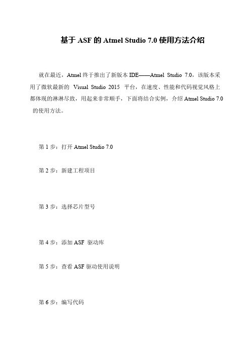
config_port_pin.input_pull = PORT_PIN_PULL_UP; //配置 IO 口上拉 port_pin_set_config(KEY, &config_port_pin); //初始化 KEY 对应 IO 口 }
/*************************************************************** *********/ //* 主程序
/*************************************************************** *********/ int main (void)
{ system_init(); //系统初始化 /* Insert application code here, after the board has been initialized. */ port_init(); //IO 初始化 while(1) { if (port_pin_get_input_level(KEY) == 0) //KEY 按下,LED 对应 IO 电平 = 0 {
基于 ASF 的 Atmel Studio 7.0 使用方法介绍
就在最近,Atmel 终于推出了新版本 IDE——Atmel Studio 7.0,该版本采 用了微软最新的 Visual Studi非常顺手,下面将结合实例,介绍 Atmel Studio 7.0
port_pin_set_output_level(LED, 0); } else { port_pin_set_output_level(LED, 1); } } }
第 7 步:编译并生产烧录文件 第 8 步:烧录文件到开发板
AtmelASF4软件架构介绍和AtmelStart开发实践

Atmel ASF4软件架构介绍与Atmel Start开发实践ASF4Kevin Liu(*********************)2017.11Atmel ASF4软件架构介绍From Atmel ASF3to ASF4ATMEL ASF4软件架构介绍Atmel开发工具覆盖完整的产品开发流程从产品选型,到软件开发,最后到产品原型和量产–Atmel提供的软件和工具都可以帮您覆盖到为什么选择Atmel Start●基于网络,不需要安装到本地●连接到My Atmel,即可更新到最新版本.●选择软件组件,参考例程或者参考解决方案●选择Atmel评估板和参考例程/解决方案●免费提供各种软件组件●Atmel官方例程,第三方软件(RTOS或TCP/IP)和开源组织软件●可视化的软件组件&设备配置管理●可配置化的软件中间件和驱动●MCU管脚复用选择,外设和系统时钟配置●自动生成干净和可读化的软件,提供在线预览●多种IDE选择–生成的软件代码/工程可以支持Atmel Studio 7, IAR和Keil图表化的软件配置可视化的系统和外设时钟配置配置IO管脚复用软件工程在线预览Implementation examplesincluded, in driver_examples.cThese examples & commentsbecome your quickstart guide.工程的在线导出和本地导入工程的重新配置ATMEL START更新和重新导出工程配置ATMEL STUDIO选择在Atmel Studio上重新配置工程CMSIS配置注释●由ARM公司进行定义●该注释用于将信息解释给可配置GUI●为开发者提供可读性的帮助文档// <o> Frame parity// <0x0=>No parity// <0x1=>Even parity// <0x2=>Odd parity#define CONF_SERCOM_1_USART_PARITY 0x0CMSIS配置注释Atmel Software Framework为什么升级到ASF4⏹Atmel Start配置工具取代ASF Wizard,新工具生成的代码是ASFv4⏹ASFv4是Atmel Software Framework一个大版本升级,重构代码结构,降低代码容量、提升运行效率⏹ASFv4无法对ASFv3代码提供100%兼容,尽管两者的代码风格类似⏹ASFv4将会成为主要的软件平台新加入的MCU只提供ASFv4的支持某些型号MCU会同时提供ASFv3和ASFv4支持⏹ASFv3支持会继续(只限于Bug修正)IOCLOUD AGENTWI-FI CRYPTO AUTH LIB SMART PLUGHARDWAREWINC1500D21ECC508SAMW25D21I/O1ECC508WINC1500SAML22HAL HPL HRIUSARTHAL HPL HRIADCLow powerSensorsConnectivitySecuritySoftware / Dev. Tools EcosystemIoT Building Blocks...工程目录结构Atmel START 生成的ASF4项目目录架构Atmel STARTIDE, e.g.Atmel StudioAtmel Start –ASFv4用户接口用户模型抽象模型●Make configuration selection using:●Field names●Dropdown(下拉菜单)options●Mouse-over pop-up (soon with REGISTERNAME.BITFIELD)●Link to datasheet register description in HTML (soon)●Register values calculated based on selection & code generated.User Model: Programming refHPLHRIHardware Abstraction LayerHardware Proxy LayerHardware Register InterfaceHAL IOAbstract deviceAtmel Start –ASFv4User Interface User Model Technical Model●Advanced, device specific features●Datasheet may be required to understand configurationUser Model: Programming refHPLHRIHardware Abstraction LayerHardware Proxy LayerHardware Register InterfaceHAL IOAbstract deviceAtmel Start –ASFv4User Interface User Model Technical Model•hri_sercomi2cm_set_CTRLA_ENABLE_bit();•hri_sercomusart_set_CTRLA_MODE_bf();•hri_sercomspi_set_CTRLA_reg();Hardware Register Interface最接近低层硬件实现,简单的bit 位操作.数据配置来源于根据芯片的手册和不同版本IP 核.访问模式:bit, bit field and register函数接口:set, get, write, read, clear, toggleHPLHRIHardware Abstraction LayerHardware Proxy LayerHardware Register InterfaceHAL IOAbstract deviceAtmel Start–ASFv4 ArchitectureHPL HRI Hardware Abstraction Layer(硬件抽象层)通过引入硬件抽象层使得可以使用相同的API接口来支持不同的设备(上层应用代码只是针对抽象接口编程,实现抽象和具体实现的剥离) Hardware Proxy Layer(硬件代理层)最上层的硬件实现,对于所有可兼容性外设模块来说都是通用的Hardware Register Interface(硬件寄存器接口)最接近硬件寄存器,简单的bit操作接口.会因为芯片参数和不同IP版本存在差异.访问模式:bit,bit field and register函数接口集合:set, get, write, read, clear, toggleHALIO•hri_sercomi2cm_set_CTRLA_ENABLE_bit();•hri_sercomusart_set_CTRLA_MODE_bf();•hri_sercomspi_set_CTRLA_reg();ASF 3 vs. Atmel Start + ASF4运行时配置:在工程中进行配置修改●配置结构体成员复杂●在代码运行时解决配置依赖性和计算配置结果,导致工程增加了额外代码开销通用驱动●尝试在一个模块中支持驱动所有特性●支持的驱动特性列表会因设备不同而改变●针对不同的设备大量使用#ifdef来使能/禁止驱动的特性,影响到代码的可读性●共用一个TC驱动(PWM,定时器和捕获)通用外设API接口●通常会增加顶层驱动包装层●不同的函数接口预编译配置:在Atmel Start中进行配置修改●配置结构体增加编译时间●在编译时解决配置依赖性和计算配置结果基于用例驱动的驱动模块●支持驱动特性子集●对于所有设备驱动特性列表都是一样的●驱动代码更加适配于目标应用●针对PWM,定时器,和输入捕获有专门驱动通用外设API接口●所有HAL APIs的设计就是为了解决不同设备的差异性●HAL的实现不会因为不同的设备而改变●(What common APIs should have been)ASFv3ASFv4ASF 3 vs. Atmel Start + ASF4 ASFv3Atmel START + ASFv4Atmel Start + ASF4系统初始化流程atmel_start.cdriver_init.c初始化MCU(晶振,时钟,flash访问等待时间…)配置GPIO,和PINMUX配置器中的配置是一致的将配置写入外设控制寄存器Atmel Start开发实践使用Atmel Start快速创建SAM54Xplained工程ATMEL START开发实践(在浏览器中创建样例工程)在浏览器中创建样例工程:步骤1:浏览器输入步骤2:选择CREATE NEW PROJECT(选择工程所采用的MCU平台)选择MCU平台:步骤1:RESULTS输入SAM E54关键字进行过滤步骤2:根据过滤结果选择SAM E54Xplained Pro步骤3:选择CREATE NEW PROJECT,开始创建SAM E54用户工程等待工程创建完成(可能需要1分钟左右)(修改创建的工程名称)修改创建的工程名称:步骤1:单击激活MY PROJECT选项步骤2:选择Rename component步骤3:在弹出的RENAMECOMPONENT窗口中输入所需要的工程名称(添加软件组件-应用/中间件/驱动)添加软件组件:单击Add software component菜单,激活ADD SOFTWARECOMPONENT功能步骤1:输入所需要添加的组件关键字步骤2:选择将组件添加到工程步骤3:在SELECTED COMPONENTS通过-/+选项修改组件数量,如需要2个USART,则将USARTCount修改为2步骤四:点击Add component(s)完成应用/中间件/驱动的添加(组件支持查看帮助文档/重命名/移出操作)组件所支持的操作:步骤1:单击激活对应的组件步骤2:可以选择:✓User guide✓Rename component✓Remove component备注:User Guide选项提供连接,可以直接跳转到对应组件的的在线的帮助文档(定制化系统时钟配置-1)系统时钟的定制:步骤1:选择外部时钟和内部锁相环步骤2:配置Generic clock generator步骤3:为COMPONENTS选择快速/慢速时钟源备注:✓Generic clock generator0(CPU Core时钟来源,可直接来自外部时钟或者锁相环DPLLx)✓DPLLx输入必须<= 3MHz✓Generic clock generatorx可以配置分频比(定制化系统时钟配置-2)XOSC1的配置:备注1:以下选项必须勾选✓Oscillator enable✓Crystal connected toXIN/XOUT Enable备注2:✓Run in Standby(如果选中XOSC1在系统进入Standby模式下不会关闭时钟)✓Clock Failure Detector(如果选中当XOSC1异常时会产生中断)(定制化系统时钟配置-3)DPLL1的配置:备注1:(定制化系统时钟配置-4)Generic clock generator0的配置:备注1:(定制化系统时钟配置-5)Generic clock generator3的配置:备注1:✓Divide Selection为enable,输出频率=Input / 2^Generic division✓Divide Selection为disable,输出频率=input / Generic division备注2:✓Run in Standby选型–通用时钟发生器在芯片进入Standby时是否需要关掉(定制化系统时钟配置-6)CPU Clock的配置:备注1:(定制化外设驱动配置-SPI)外设驱动的定制:步骤1:选择需要定制的驱动组件步骤2:在COMPONENTS SETTINGS选择SPI所使用的SERCOM步骤3:在SIGNALS配置SPI信号管脚步骤4:在BASIC CONFIGURATION修改SPI速率等参数备注:可以通过BASIC CONFIGURATION进行更多配置(定制化外设驱动配置-UART debug)外设UART驱动的定制:备注:配置一个UART作为调试打印接口,参考SAME54Xplained Pro原理图和SAME54 datasheet来分配管脚(定制化外设驱动配置-ADC)外设ADC驱动的定制:备注:演示如何配置ADC,来实现对外接光线传感器的支持,中间参考了SAME54Xplained Pro原理图和SAME54 datasheet管脚分配和Sensor扩展板接口说明。
INMASRSAT F站一般操作规程

INMASRSA T F站一般操作规程
1.启动
1)打开主机背板右侧电源按钮。
此时,主机、控制手柄、报警单元和天线单元电源开启。
同时,控制手柄及报警盒上的所有指示灯均亮几秒,进行灯自检,完毕后熄灭,只有电源指示灯亮,表明电源正常。
2)电源启动后,系统将按依次显示”Initialising”,”Wait for NCS”,”Wait for GPS”,”READY”,在显示”READY”时,本系统可以正常使用。
2.选择洋区
按MENU→用↑↓选择AREA→OK→用↑↓选择所需洋区→OK→EXIT.
3.选择岸站
按MENU→用↑↓选择Default LES→OK→用↑↓选择所需岸站→OK→EXIT。
4.实验通信
可以进行常规通信,遇险通信,传真通信。
5.关机
关闭主机背板右侧电源按钮,主机关闭。
- 1、下载文档前请自行甄别文档内容的完整性,平台不提供额外的编辑、内容补充、找答案等附加服务。
- 2、"仅部分预览"的文档,不可在线预览部分如存在完整性等问题,可反馈申请退款(可完整预览的文档不适用该条件!)。
- 3、如文档侵犯您的权益,请联系客服反馈,我们会尽快为您处理(人工客服工作时间:9:00-18:30)。
Atmel asf学习笔记前言前一段时间入手了一块Arduino DUE开发板,入手后网上查询资料发现资料很少,并且和很多的模块不兼容,这块板子的IO口只能承受3.3v的电压,如果想使用5v的模块,又要动手做兼容模块。
又因为这块板子采用的MCU是SAM3X8E 是一款ARM的主控,就想把它作为cortex M3开发板使用。
环境搭建开发工具:atmel studio 6.1烧写工具:bossac.exe开发工具可以在Atmel官网下载,bossac.exe可以从arduino中提取建立工程为了快速上手这块板子,我决定采用atmel的asf框架创建示例工程,由于在单片机程序开发中,需要通过串口输入输出调试信息,所以首先要实现串口通讯,这里先创建一个串口通讯程序的模板接下来就ok了编译通过下载到mcu中接下来打开串口,查看输出信息测试通过!ASF之串口学习#include <string.h>#include "asf.h"//包含了所需要的模块#include "stdio_serial.h"//串口的出入输出定义#include "conf_board.h"#include "conf_clock.h"#include "conf_example.h"//定义了串口中断入口函数,波特率,串口端口号/** Size of the receive buffer used by the PDC, in bytes. */#define BUFFER_SIZE 100 //定义外设DMA控制器缓冲区大小(字节)/** USART PDC transfer type definition. */#define PDC_TRANSFER 1 //串口发送类型定义/** USART FIFO transfer type definition. */#define BYTE_TRANSFER 0 //串口发送队列类型定义/** Max buffer number. */#define MAX_BUF_NUM 1/** All interrupt mask. */#define ALL_INTERRUPT_MASK 0xffffffff/** Timer counter frequency in Hz. */#define TC_FREQ 1#define STRING_EOL "\r"#define STRING_HEADER "-- USART Serial Example --\r\n" \"-- "BOARD_NAME" --\r\n" \"-- Compiled: "__DATE__" "__TIME__" --"STRING_EOL/** Receive buffer. */static uint8_t gs_puc_buffer[2][BUFFER_SIZE];/** Next Receive buffer. */static uint8_t gs_puc_nextbuffer[2][BUFFER_SIZE];/** Current bytes in buffer. */static uint32_t gs_ul_size_buffer = BUFFER_SIZE;/** Current bytes in next buffer. */static uint32_t gs_ul_size_nextbuffer = BUFFER_SIZE;/** Byte mode read buffer. */static uint32_t gs_ul_read_buffer = 0;/** Current transfer mode. */static uint8_t gs_uc_trans_mode = PDC_TRANSFER;///** Buffer number in use. */static uint8_t gs_uc_buf_num = 0;/** PDC data packet. */pdc_packet_t g_st_packet, g_st_nextpacket;/** Pointer to PDC register base. */Pdc *g_p_pdc;/** Flag of one transfer end. */static uint8_t g_uc_transend_flag = 0;/*** \brief Interrupt handler for USART. Echo the bytes received and start the* next receive.*/void USART_Handler(void){uint32_t ul_status;/* Read USART Status. *///函数返回p_usart->US_CSR,USART0的基地址((Usart *)0x40098000U) ,US_CSR 的偏移地址0x0014//由于c语言为结构体分配的空间是连续的所以很容易实现基地址+偏移地址ul_status = usart_get_status(BOARD_USART);//判断当前的传输模式是否为DMA方式if (gs_uc_trans_mode == PDC_TRANSFER) {/* Receive buffer is full. *///? RXBUFF: Reception Buffer Full//0: The signal Buffer Full from the Receive PDC channel is inactive.//1: The signal Buffer Full from the Receive PDC channel is active//在这里默认是1 在这里做与运算只要US_CSR_RXBUFF为1 结果就为真if (ul_status & US_CSR_RXBUFF) {/* Disable timer. */tc_stop(TC0, 0);/* Echo back buffer. *///g_st_packet 有两个元素//1:The pointer to packet data start address. For pointer or next pointer//2:Size for counter or next counter register (_CR)g_st_packet.ul_addr =(uint32_t)gs_puc_buffer[gs_uc_buf_num];g_st_packet.ul_size = gs_ul_size_buffer;g_st_nextpacket.ul_addr =(uint32_t)gs_puc_nextbuffer[gs_uc_buf_num];g_st_nextpacket.ul_size = gs_ul_size_nextbuffer;//DMA发送初始化pdc_tx_init(g_p_pdc, &g_st_packet, &g_st_nextpacket);if (g_uc_transend_flag) {gs_ul_size_buffer = BUFFER_SIZE;gs_ul_size_nextbuffer = BUFFER_SIZE;g_uc_transend_flag = 0;}gs_uc_buf_num = MAX_BUF_NUM - gs_uc_buf_num;/* Restart read on buffer. */g_st_packet.ul_addr =(uint32_t)gs_puc_buffer[gs_uc_buf_num];//数组的地址空间是连续的g_st_packet.ul_size = BUFFER_SIZE;g_st_nextpacket.ul_addr =(uint32_t)gs_puc_nextbuffer[ gs_uc_buf_num];g_st_nextpacket.ul_size = BUFFER_SIZE;//DMA接收初始化pdc_rx_init(g_p_pdc, &g_st_packet, &g_st_nextpacket);/* Restart timer. */tc_start(TC0, 0);}} else {/* Transfer without PDC. */if (ul_status & US_CSR_RXRDY) {usart_getchar(BOARD_USART, (uint32_t *)&gs_ul_read_buffer);usart_write(BOARD_USART, gs_ul_read_buffer);}}}/*** \brief Interrupt handler for TC0. Record the number of bytes received,* and then restart a read transfer on the USART if the transfer was stopped.*/void TC0_Handler(void){uint32_t ul_status;uint32_t ul_byte_total = 0;/* Read TC0 Status. */ul_status = tc_get_status(TC0, 0);/* RC compare. */if (((ul_status & TC_SR_CPCS) == TC_SR_CPCS) &&(gs_uc_trans_mode == PDC_TRANSFER)) {/* Flush PDC buffer. */ul_byte_total = BUFFER_SIZE - pdc_read_rx_counter(g_p_pdc);//缓冲区既没用完,也没有没用if ((ul_byte_total != 0) && (ul_byte_total != BUFFER_SIZE)) { /* Log current size. */g_uc_transend_flag = 1;if (pdc_read_rx_next_counter(g_p_pdc) == 0) {gs_ul_size_buffer = BUFFER_SIZE;gs_ul_size_nextbuffer = ul_byte_total;} else {gs_ul_size_buffer = ul_byte_total;gs_ul_size_nextbuffer = 0;}/* Trigger USART Receive Buffer Full Interrupt. */pdc_rx_clear_cnt(g_p_pdc);}}}/*** \brief Configure USART in normal (serial rs232) mode, asynchronous, * 8 bits, 1 stop bit, no parity, 115200 bauds and enable its transmitter* and receiver.*/static void configure_usart(void){const sam_usart_opt_t usart_console_settings = {BOARD_USART_BAUDRATE,US_MR_CHRL_8_BIT,US_MR_PAR_NO,US_MR_NBSTOP_1_BIT,US_MR_CHMODE_NORMAL,/* This field is only used in IrDA mode. */};/* Enable the peripheral clock in the PMC. */sysclk_enable_peripheral_clock(BOARD_ID_USART);/* Configure USART in serial mode. */usart_init_rs232(BOARD_USART, &usart_console_settings,sysclk_get_cpu_hz());/* Disable all the interrupts. */usart_disable_interrupt(BOARD_USART, ALL_INTERRUPT_MASK);/* Enable the receiver and transmitter. */usart_enable_tx(BOARD_USART);usart_enable_rx(BOARD_USART);/* Configure and enable interrupt of USART. */NVIC_EnableIRQ(USART_IRQn);}/*** \brief Configure Timer Counter 0 (TC0) to generate an interrupt every 200ms. * This interrupt will be used to flush USART input and echo back.*/static void configure_tc(void){uint32_t ul_div;uint32_t ul_tcclks;static uint32_t ul_sysclk;/* Get system clock. */ul_sysclk = sysclk_get_cpu_hz();/* Configure PMC. */pmc_enable_periph_clk(ID_TC0);/* Configure TC for a 50Hz frequency and trigger on RC compare. */tc_find_mck_divisor(TC_FREQ, ul_sysclk, &ul_div, &ul_tcclks, ul_sysclk);tc_init(TC0, 0, ul_tcclks | TC_CMR_CPCTRG);tc_write_rc(TC0, 0, (ul_sysclk / ul_div) / TC_FREQ);/* Configure and enable interrupt on RC compare. */NVIC_EnableIRQ((IRQn_Type)ID_TC0);tc_enable_interrupt(TC0, 0, TC_IER_CPCS);}/*** Configure UART for debug message output.*/static void configure_console(void){const usart_serial_options_t uart_serial_options = {.baudrate = CONF_UART_BAUDRA TE,.paritytype = CONF_UART_PARITY};/* Configure console UART. */sysclk_enable_peripheral_clock(CONSOLE_UART_ID);stdio_serial_init(CONF_UART, &uart_serial_options); }/*** \brief Reset the TX & RX, and clear the PDC counter.*/static void usart_clear(void){/* Reset and disable receiver & transmitter. */usart_reset_rx(BOARD_USART);usart_reset_tx(BOARD_USART);/* Clear PDC counter. */g_st_packet.ul_addr = 0;g_st_packet.ul_size = 0;g_st_nextpacket.ul_addr = 0;g_st_nextpacket.ul_size = 0;pdc_rx_init(g_p_pdc, &g_st_packet, &g_st_nextpacket);/* Enable receiver & transmitter. */usart_enable_tx(BOARD_USART);usart_enable_rx(BOARD_USART);}/*** \brief Display main menu.*/static void display_main_menu(void){puts("-- Menu Choices for this example --\r\n""-- s: Switch mode for USART between PDC and without PDC.--\r\n""-- m: Display this menu again.--\r");}/*** \brief Application entry point for usart_serial example.** \return Unused (ANSI-C compatibility).*/int main(void){uint8_t uc_char;uint8_t uc_flag;/* Initialize the SAM system. */sysclk_init();board_init();/* Configure UART for debug message output. */configure_console();/* Output example information. */puts(STRING_HEADER);/* Configure USART. */configure_usart();/* Get board USART PDC base address. */g_p_pdc = usart_get_pdc_base(BOARD_USART);/* Enable receiver and transmitter. */pdc_enable_transfer(g_p_pdc, PERIPH_PTCR_RXTEN | PERIPH_PTCR_TXTEN);/* Configure TC. */configure_tc();/* Start receiving data and start timer. */g_st_packet.ul_addr = (uint32_t)gs_puc_buffer[gs_uc_buf_num];g_st_packet.ul_size = BUFFER_SIZE;g_st_nextpacket.ul_addr = (uint32_t)gs_puc_nextbuffer[gs_uc_buf_num];g_st_nextpacket.ul_size = BUFFER_SIZE;pdc_rx_init(g_p_pdc, &g_st_packet, &g_st_nextpacket);puts("-- Start to echo serial inputs -- \r\n""-I- Default Transfer with PDC \r\n""-I- Press 's' to switch transfer mode \r");gs_uc_trans_mode = PDC_TRANSFER;usart_disable_interrupt(BOARD_USART, US_IDR_RXRDY);usart_enable_interrupt(BOARD_USART, US_IER_RXBUFF);tc_start(TC0, 0);while (1) {uc_char = 0;uc_flag = uart_read(CONSOLE_UART, &uc_char);if (!uc_flag) {switch (uc_char) {case 's':case 'S':if (gs_uc_trans_mode == PDC_TRANSFER) {/* Transfer to no PDC communication mode. *//* Disable PDC controller. */pdc_disable_transfer(g_p_pdc,PERIPH_PTCR_RXTDIS | PERIPH_PTCR_TXTDIS);/* Disable the RXBUFF interrupt. */usart_disable_interrupt(BOARD_USART, US_IDR_RXBUFF);/* Clear USART controller. */usart_clear();/* Enable the RXRDY interrupt. */usart_enable_interrupt(BOARD_USART, US_IER_RXRDY);gs_uc_trans_mode = BYTE_TRANSFER;puts("-I- Transfer without PDC \r");} else if (gs_uc_trans_mode == BYTE_TRANSFER) {pdc_enable_transfer(g_p_pdc,PERIPH_PTCR_RXTEN | PERIPH_PTCR_TXTEN);/* Clear USART controller. */usart_clear();/* Reset pdc current buffer size. */gs_ul_size_buffer = BUFFER_SIZE;gs_ul_size_nextbuffer = BUFFER_SIZE;gs_uc_buf_num = 0;/* Start receiving data. */g_st_packet.ul_addr =(uint32_t)gs_puc_buffer[gs_uc_buf_num];g_st_packet.ul_size = BUFFER_SIZE;g_st_nextpacket.ul_addr =(uint32_t)gs_puc_nextbuffer[gs_uc_buf_num];g_st_nextpacket.ul_size = BUFFER_SIZE;pdc_rx_init(g_p_pdc, &g_st_packet, &g_st_nextpacket);/* Transfer to PDC communication mode, disable RXRDY interrupt and enable RXBUFF interrupt. */usart_disable_interrupt(BOARD_USART, US_IER_RXRDY);usart_enable_interrupt(BOARD_USART, US_IER_RXBUFF);gs_uc_trans_mode = PDC_TRANSFER;puts((const char *)gs_puc_nextbuffer[0]);puts("-I- Transfer with PDC \r");}break;case 'm':case 'M':display_main_menu();break;default:break;}}}}。
