TB6612FNG驱动模块使用说明
学校人工智能实验室配置清单
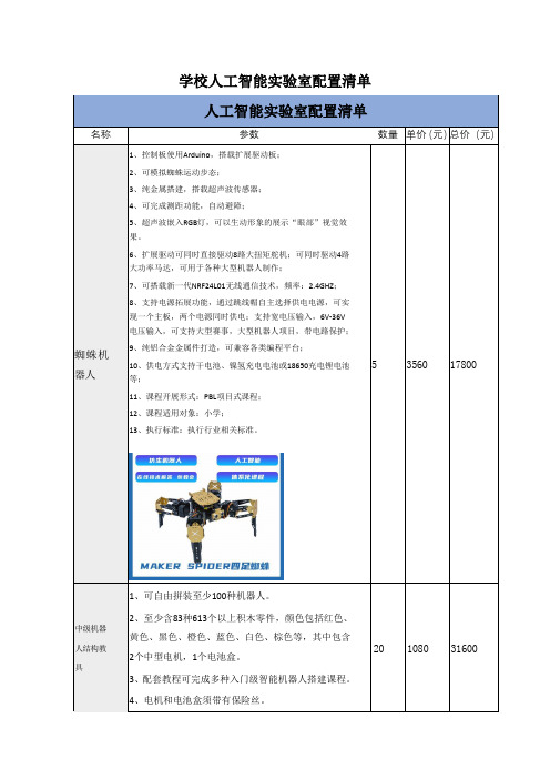
学校人工智能实验室配置清单1、控制板使用Arduino,搭载扩展驱动板;2、可模拟蜘蛛运动步态;3、纯金属搭建,搭载超声波传感器;4、可完成测距功能,自动避障;5、超声波嵌入RGB灯,可以生动形象的展示“眼部”视觉效果。
6、扩展驱动可同时直接驱动8路大扭矩舵机;可同时驱动4路大功率马达,可用于各种大型机器人制作;7、可搭载新一代NRF24L01无线通信技术,频率:2.4GHZ;8、支持电源拓展功能,通过跳线帽自主选择供电电源,可实现一个主板,两个电源同时供电;支持宽电压输入,6V-36V电压输入,可支持大型赛事,大型机器人项目,带电路保护;9、纯铝合金金属件打造,可兼容各类编程平台;10、供电方式支持干电池、镍氢充电电池或18650充电锂电池等;11、课程开展形式:PBL项目式课程;12、课程适用对象:小学;13、执行标准:执行行业相关标准。
5、配套教程应分为教师版和学生版。
6、配套课程中涉及课题不低于17个。
1、供电方式支持干电池、镍氢充电电池或18650充电锂电池等。
2、控制板使用AVR MEGA328处理器,有复位按键,至少拥有2路电机输出及8个扩展接口,接口使用USB Type-A,支持PS2遥控手柄控制。
3、套装清单至少包含:超声波测距传感器x1,TT双出轴减速电机x2,红色LEDx1,绿色LED模块x1,红色LED模块x1,触摸传感器模块x1,双路可调循迹传感器模块x1,有源蜂鸣器模块x1,PS2接收模块x1、铝合金壳体x1,专用螺丝刀x1,18650电池盒x1,18650电池x2,水晶连接线x4,USB数据线x1,螺丝包x1,万向轮x1,包胶大轮胎x2,魔术带双面胶x1,PS无线遥控手柄x1。
4、各传感器模块与主控制器相互独立,可独立用于其它课程。
3、套装清单至少应包含:超声波测距传感器模块x1,电位器模块x1,灰度传感器模块x2,有源蜂鸣器模块x1,可燃气体传感器模块x2,光敏传感器模块x1,按键模块x1,触摸开关模块x1,全彩LED模块x1,火焰传感器模块x1,声音传感器模块x1、PS2遥控接收器模块x1,OLED显示屏模块模块x1,水晶头连接线x4,Type-C数据线x1,积木供电转接线x5。
TB6612FNG简介及其与单片机的直流电机控制系统设计

TB6612FNG简介及其与单片机的直流电机控制系统设计介绍TB6612FNG及其电机控制单片机系统设计时间:2012-01-23 13:28:29来源:电子设计工程作者:卢桓本设计中使用的TB6612FNG是一种新型驱动装置。
两台DC电机可以独立双向控制。
它具有高集成度、足够的输出能力以及在运行性能和能耗方面的优势。
因此,它可以用作集成和小型化电机控制系统中的理想电机驱动装置。
介绍1 TB 6612 FNGTB 6612 FNG是东芝半导体公司生产的DC电机驱动装置。
它具有大电流MOSFET-H桥结构,双通道电路输出,并能同时驱动两个电机。
TB6612FNG每通道输出高达1.2 A的连续驱动电流,起始峰值电流达到2A/3.2 A(连续脉冲/单脉冲);四种电机控制模式:正转/反转/制动/停止;脉宽调制支持高达100千赫的频率;待机状态;片上低压检测电路和热关断保护电路;工作温度:-20 ~ 85℃;SSOP24小补丁包如图1所示,TB6612FNG的主要引脚功能为:AINl/AIN2、BIN1/BIN2、PWMA/PWMB作为控制信号输入端;AO1/A02和B01/B02是双向电机控制输出端子;STBY是正常运行/备用状态控制引脚;Vm (4.5 ~ 15 v)和VCC (2.7 ~ 5.5 v)分别是电机驱动电压输入和逻辑电平输入TB6612FNG是一种基于MOSFET的H桥集成电路,其效率高于晶体管H桥驱动器与L293D每通道600毫安的平均驱动电流和1.2安的脉冲峰值电流相比,其输出负载能力增加了一倍。
与L298N的散热和外围二极管续流电路相比,它不需要额外的散热器,外围电路简单。
电机只能由外部电源滤波电容直接驱动,有利于减小系统尺寸。
对于脉宽调制信号,它支持高达100千赫的频率,与上述两种芯片的5千赫和40千赫相比有很大优势。
2电机控制单元设计2.1单元硬件组成图2显示了一个由TB6612FNG和A VR单片机组成的电机控制单元单片机定时器产生4个脉宽调制输出,作为AIN1/AIN2和BIN1/BIN2控制信号,如图2中OCxA和0CxB对电机M1和M2的控制所示采用定时器输出硬件脉宽调制脉冲,使得单片机的中央处理器只在脉宽调制占空比发生变化时才参与计算,大大减轻了系统的计算负担和脉宽调制软件的编程成本输入引脚PWMA、PWMB和STBY通过输入/输出电平控制电机的运行或制动状态以及设备的运行状态。
基于单片机的两轮自平衡车控制系统设计

基于单片机的两轮自平衡车控制系统设计摘要两轮自平衡车是一种高度不稳定的两轮机器人,就像传统的倒立摆一样,本质不稳定是两轮小车的特性,必须施加有效的控制手段才能使其稳定;本文提出了一种两轮自平衡小车的设计方案,采用重力加速度陀螺仪传感器MPU-6050检测小车姿态,使用互补滤波完成陀螺仪数据与加速度计数据的数据融合;系统选用STC公司的8位单片机STC12C5A60S2为主控制器,根据从传感器中获取的数据,经过PID 算法处理后,输出控制信号至电机驱动芯片TB6612FNG,以控制小车的两个电机,来使小车保持平衡状态;整个系统制作完成后,小车可以在无人干预的条件下实现自主平衡,并且在引入适量干扰的情况下小车能够自主调整并迅速恢复至稳定状态;通过蓝牙,还可以控制小车前进,后退,左右转;关键词:两轮自平衡小车加速度计陀螺仪数据融合滤波 PID算法Design of Control System of Two-Wheel Self-Balance Vehicle based onMicrocontrollerAbstractTwo-wheel self-balance vehicle is a kind of highly unstable two-wheel robot. The characteristic of two-wheel vehicle is the nature of the instability as traditional inverted pendulum, and effective control must be exerted if we need to make it stable. This paper presents a design scheme of two-wheel self-balance vehicle. We need using gravity accelerometergyroscope sensor MPU6050 for the inclination angle of vehicle, and using complementary filter for the data fusion of gyroscope and accelerometer. We choose an 8-bit microcontroller named STC12C5A60S2 from STC Company as main controller of the control system. The main controller output control signal, which is based on the data from the sensors, to the motor drive chip named TB6612FNG for controlling two motors of vehicle, and keeping the vehicle in balance. After the completion of the control system, the vehicle can achieve autonomous balance under the conditions of unmanned intervention, the vehicle can adjust automatically and restored to a stable state quickly in the case of giving appropriate interference as well. In addition, we can control the vehicle forward, backward and turn around. Key words: Two-Wheel Self-Balance Vehicle; Accelerometer; Gyroscope; Data fusion;Complementary filter; PID algorithm1 绪论自平衡小车的研究背景近几年来,随着电子技术的发展与进步,移动机器人的研究不断深入,成为目前机器人研究领域的一个重要组成部分,并且其应用领域日益广泛,其所需适应的环境和执行的任务也更复杂,这就对移动机器人提出了更高的要求;比如,户外移动机器人需要在凹凸不平的地面上行走,有时机器人所需要运行的地方比较狭窄等;如何解决机器人在这些环境中运行的问题,已成为现实应用中所需要面对的一个问题;两轮自平衡小车就是在这些的需求下所产生的;这种机器人相对于其他移动机器人的最显着特点是:采用了两轮共轴、各自独立驱动的方式工作,车身重心位于车轮轴上方,通过车轮的前后滚动来保持车身的动态平衡,并可以在直立平衡状态下完成前进、后退、左右转等任务;正是由于其特殊的构造,两轮自平衡小车适应地形变化的能力较强,且运动灵活,可以胜任一些复杂环境中的工作;两轮自平衡车自面世以来,一直受到世界各国机器人爱好者和研究者的关注,这不仅是因为两轮自平衡车具有独特的外形和结构,更重要的是因为其自身的本质不稳定性和非线性使它成为很好的验证控制理论和控制方法的平台,具有很高的研究价值;早在1987年,日本电信大学教授山藤一雄就提出了两轮自平衡机器人的概念;这个基本的概念就是用数字处理器来侦测平衡的改变,然后以平行的双轮来保持机器的平稳;本世纪初;美国发明家狄恩·卡门与他的DEKA公司研发出了可以用于载人的两轮自平衡车,并命名为赛格威,投入市场后,引发了自平衡车的流行;由于两轮自平衡车有着活动灵活,环境无害等优点,其被广泛应用于各类高规格社会活动中,目前该车已用于奥运会、世博会、机场、火车站等大型场合;自平衡小车研究意义由于两轮自平衡小车具有结构特殊、体积小、运动灵活、适应地形变化能力强、能够方便的实现零半径回转、适合在拥挤和危险的空间内活动、可以胜任一些复杂环境里的工作;因此两轮自平衡车有着广泛的应用前景,其典型应用包括代步工具、通勤车、空间探索、危险品运输、高科技玩具、控制理论测试平台等方面;目前自平衡车的应用如自平衡的代步车正在流行开来;因此两轮自平衡车的研究很有意义;论文的主要内容本论文主要叙述了基于单片机的两轮自平衡车控制系统的设计与实现的整个过程;主要内容为两轮自平衡小车的平衡原理,直立控制,蓝牙控制;整个内容分为六章,包括绪论、课题任务与关键技术、系统原理概述、系统硬件设计、系统软件设计和系统的机械安装及调试;第一章主要讲解了课题的研究背景及意义,国内外研究现状;第二章主要讲解了设计的主要任务与所需的关键技术;第三章主要讲解了两轮自平衡小车控制系统的直立控制原理,转向控制原理;第四章主要讲解了系统的硬件设计,介绍了自平衡小车控制系统的硬件构成,主控芯片STC12C5A60S2的结构及组成,以及稳压电源模块,倾角测量模块,直流电机驱动模块,蓝牙控制模块和两轮测速模块的设计;第五章主要讲解了软件设计的算法功能与框架,主要描述了控制系统的程序实现以及PID算法的使用;第六章主要讲解了系统的调试与参数整定;最后总结与展望,总结本设计的各个模块,并对两轮自平衡小车的优化方向进行简要的阐述;2 课题任务与关键技术主要任务本文研究并设计了一种基于单片机的两轮自平衡小车控制系统,实现了两轮小车的自主直立控制与蓝牙控制功能;系统采用STC12C5A60S2单片机作为核心控制单元,通过增加各种传感器,设计相应电路并编写相应程序完成平衡控制与蓝牙控制;系统需要利用加速度计和陀螺仪获得车体的倾角和角速度,并对数据进行互补滤波融合;通过编码器获得两轮的速度信息;根据获得的数据信息对速度和倾角进行闭环控制;加入蓝牙通信控制,将所有输出数据进行叠加,输出至驱动芯片,实现对小车的控制;关键技术系统设计两轮自平衡车的系统设计包括:车身机械结构设计,硬件系统设计和软件系统设计;在机械结构上必须保持小车重心的稳定性,才能避免控制系统过于复杂;硬件系统必须包含自平衡车所需的所有电子系统与电气设备;软件系统则负责车身平衡控制与目标效果的实现;数学建模模型的建立有助于控制器的设计,以及控制系统各项参数的大概确定;模型的建立主要使用牛顿力学定律;姿态检测两轮自平衡车是一个本质不平衡的系统,控制系统对小车的精确控制依赖于姿态检测系统对车身姿态及运动状态的精确检测;目前,一般采用由陀螺仪和加速度计等惯性传感器组成的姿态检测系统对车身倾角进行实时、准确的检测;但是由于惯性传感器自身固有的特性,随着温度、震动等外界变化,会产生不同程度的噪声与漂移,因此必须采用一些滤波算法,对加速度计和陀螺仪所采集的数据进行融合,使测量角度更加真实稳定;控制算法两轮自平衡车所实现的平衡是一种动态的平衡;在遇到外界干扰时,需要通过控制算法来快速将小车恢复至平衡状态;传统的PID算法在各类工业场合有着广泛的应用,完全可以满足本控制系统的要求,因此本控制系统设计采用PID控制算法;3 系统原理分析控制系统任务分解根据系统要求,小车必须能够在没有外界干预的情况下依靠两个同轴安装的车轮保持平衡,并完成前进,后退,左右转等动作;相对于四轮车,控制系统的任务更为复杂,为了能解决该问题,首先将复杂的问题分解成简单的几个问题进行讨论;对系统要求进行分析,可知维持小车直立,并在受到外界干扰后迅速恢复稳态,完全依赖于一对直流电机对车轮的驱动;因此本控制系统的设计可以从对电机的控制着手,控制电机的转速以及转向来实现对小车的控制;小车的控制任务可以分解成以下三个基本任务:(1)控制小车直立:通过控制两个电机的转向保持小车的直立状态;(2)控制小车车速:通过控制两个电机的转速实现车速控制;(3)控制小车转向:通过控制两个电机的转速差实现转向控制;以上三个任务都是通过控制小车两个车轮的驱动电机完成的;直流电机的控制最终取决于电机两端输入的电压大小,将电机近似认为处于线性状态,因此上述三个基本任务可以等效成三种不同控制目标的电压,将这三种电压进行叠加后,便可以得到最终所需的电压,并将其施加在电机上以达到所追求的控制效果;在这三个任务中,保持小车平衡是关键,三个任务执行的优先级为:平衡控制>速度控制>转向控制;由于小车同时受到三种控制的影响,从平衡控制角度来看,其他两个控制就成为了它的干扰;因此对小车速度、方向的控制应该尽量保持平滑,以减少对平衡控制的干扰;上述三种控制各自独立进行,它们各自假设其他两个控制都已经达到稳定;比如控制小车加速和减速的时候,平衡控制一直在起作用,它会自动改变小车的倾角,使小车实现加速和减速;控制原理生活中有很多直立控制的例子,例如一个正常人可以经过简单的练习,让一根直木棒在水平的掌心中保持直立;这需要两个条件:一是托着木棒的手掌可以移动;二是眼睛可以观察到木棒的倾斜角和倾斜趋势角加速度;可以通过手掌的移动抵消木棒的倾斜角度和趋势,从而保持木棒的直立;这两个条件缺一不可,这就是控制中的负反馈机制;单,因为小车有两个车轮着地,因此车体只会在一个平面内发生倾斜;控制车轮转动便可抵消倾斜的趋势从而保持车体直立;数学模型二轮自平衡小车在建模时可以将其简化为倒立摆,便于进行受力分析并建立其数学模型,从而更好的设计控制系统;图 单摆模型与倒立摆模型通过对单摆模型的观察可知,当物体离开平衡位置后会受到重力与线的合作用力,驱使重物回复至平衡位置,并进行周期运动,由于空气阻力的存在,单摆最终会停在平衡位置;可以得出,单摆保持平衡的条件有两点:(1) 受到与位移方向相反的回复力作用;(2) 受到和运动速度相反的阻尼力作用;如果没有阻尼力的作用,单摆会在平衡位置左右晃动无法停止,如果阻尼力过小,单摆会在平衡位置震荡,如果阻尼力过大,则单摆的回复时间将变长,因此存在一个临界阻尼系数,使得单摆停止在平衡位置所需时间最短;车体垂直,车车体向前倾车体向后倾斜,图 通过车轮控制车体平衡倒立摆在偏离平衡位置时,受到的合力与位移方向相同,因此倒立摆不能像单摆一样稳定在垂直位置,并且会加速偏离平衡位置直至倒下;为了让倒立摆能像单摆一样平衡在稳定位置,只能通过增加额外受力使回复力与位移方向相反;控制车轮做加速运动,以小车作为参考系,重心受到一个额外的惯性力,与车轮加速度大小相同,方向相反;因此倒立摆所受到的回复力为F =mgsinθ−macosθ 3-1根据控制系统的特性,角θ需要控制在很小的范围内,并且假设控制车轮加速度与角θ成正比,比例系数为k 1,因此上式可近似处理为F =mgθ−mk 1θ 3-2此时,只要k 1>g ,回复力的方向便和位移方向相反,此时小车可以恢复到平衡位置;为使小车能在平衡位置尽快的稳定下来,还需要有阻尼力,阻尼力与角速度方向相反,大小成正比;式3-2可变为 F =mgθ−mk 1θ−mk 2θ′ 图 小车受力分析mgsinθ−macosθmgθ m3-3式中,k1,k2均为比例系数,θ为小车倾角,θ′为角速度;只要满足k1>g,k2>0,便可以将小车维持在直立状态;k2是小车回到垂直位置的阻尼系数,选取合适的阻尼系数可以保证小车可以尽快稳定在垂直位置;因此为了控制小车稳定,需要精确的测量小车倾角θ的大小和角速度θ′的大小,并以此控制车轮的加速度;4 系统硬件设计本控制系统主要由以下几个模块组成:STC12C5A60S2单片机最小系统、电源管理模块、车身姿态感应模块、电机驱动模块、速度检测模块、蓝牙模块,各模块关系图如下所示:图硬件设计总体框图STC12C5A60S2单片机介绍本控制系统采用STC12C5A60S2单片机作为控制核心;该单片机是深圳宏晶科技有限公司的典型单片机产品,采用了增强型8051内核,片内集成了60KB程序Flash、1KB数据FlashEEPROM、1280字节RAM、2个16位定时/计数器、44根I/O口线、两个全双工异步串行口UART、高速同步通信端口SPI、8通道10位ADC、2通道PWM/可编程计数器阵列/捕获/比较单元PWM/PCA/CCU、MAX810专用复位电路和硬件看门狗等资源;STC12C5A60S2具有在系统可编程ISP功能和在系统调试ISD功能,可以省去价格较高的专门编程器,开发环境的搭建非常容易,并且该单片机所有指令和标准的8051内核完全兼容,具有良好的兼容性和很强的数据处理能力;STC12C5A60S2系列单片机的内部结构框图如下所示,该单片机中包含中央处理器CPU、程序存储器Flash、数据存储器SRAM、定时/计数器、UART 串口、串口2、I/O接口、高速A/D转换、SPI接口、PCA、看门狗及片内R/C振荡器和外部晶体振荡电路等模块;STC12C5A60S2单片机几乎包含了数据采集和控制中所需的所有单元模块,可称得上一个片上系统;图 STC12C5A60S2系列内部结构框图图单片机最小系统电源管理模块电源管理模块为整个硬件电路提供所需的电源,其稳定性是整个硬件电路可靠运行的基础;为了减少各个模块之间的相互干扰,电源模块由若干相互独立的稳压电路模块组成;整个系统由三节的18650锂电池串联供电;选择LM2596S作为稳压芯片,整个系统的供电模块如下图所示;图系统供电模块示意图LM2596S开关电压调节器是降压型电源管理单片集成电路,能够输出3A的驱动电流,同时具有很好的线性和负载调节特性;该器件内部集成频率补偿和固定频率发生器,开关频率为150KHz,与低频开关调节器相比较,可以使用更小规格的滤波元件;该器件还有其他一些特点:在特定的输入电压和输出载荷的条件下,输出电压的误差可以保证在±4%的范围内,振荡频率误差在±15%的范围内;可以用仅80uA的待机电流;可实现外部断电;具有自我保护电路;该器件完全可以满足系统需要;稳压电路原理图如下图所示;图稳压电路原理图车身姿态感应模块在第三章原理分析中可知,为了控制小车稳定,需要精确的测量小车倾角θ的大小和角速度θ′的大小,并以此控制车轮的加速度,以此消除小车的倾角;因此小车倾角以及倾角的角速度的测量成为了控制小车直立的关键;测量小车倾角和角速度可以通过加速度传感器和陀螺仪实现;本控制系统的设计使用了整合性6轴运动处理组件,相较于多组件方案,免除了组合陀螺仪与加速器时的轴间差的问题,减少了大量的封装空间;MPU6050对陀螺仪和加速度计分别用了三个16位的ADC,将其测量的模拟量转化为可输出的数字量,和所有设备寄存器之间的通信采用400kHz 的I2C 接口;为了精确跟踪快速和慢速的运动,传感器的测量范围都是用户可控的,陀螺仪的可测范围为±250,±500,±1000,±2000°/秒dps,加速度计可测范围为±2,±4,±8,±16g;量程越大,测量精度越低;MPU6050实物及坐标轴示意图如下图所示;加速度计MPU6050的加速度计部分可以测量出各轴方向上的加速度,并经过AD 转换后可输出数字信号;加速度检测的基本原理如下图所示;++++X++X图 MPU6050实物图与对应坐标轴示意图 加速度检测的基本原理通过微机械加工技术在硅片上加工形成了一个机械悬臂;它与相邻的电极形成了两个电容;由于加速度使得机械悬臂与两个电极之间的距离发生了变化,从而改变了两个电容的参数;通过集成的开关电容放大电路测量电容参数的变化,形成了与加速度成正比的电压输出;只需要测量出一个轴上的加速度,便可计算出小车的倾角;如下图所示,设小车前进方向是小车直立时MPU6050的Y 轴正向;当小车前倾时,小车重心在Y 轴上所受的力便是重力在Y 轴上的分力,为mgsinθ,因此MPU6050在Y 轴上所获得的加速度为 gsinθ;似乎只需要获得加速度数据就可以获得小车的倾角,但在实际小车的运行过程中,由于小车本身的运动所产生的加速度会产生很大的干扰信号叠加在上述测量信号上,使得输出信号无法准确的反映小车的倾角,如下图所示;小车运动所产生的振动加速度使得输出电压在实际倾角电压附近波动,可以使用低通滤波将其过滤,但也会使得信号无法实时反映小车的倾角变化,从而影响对小车的控制,使得小车无法保持平衡;图 小车受力分析图 加速度计信号波动陀螺仪陀螺仪可以用来测量物体的旋转角速度,它利用了旋转坐标系中的物体会受到克里利奥力的原理,在器件中利用压电陶瓷做成振动单元;当器件旋转时会改变振动频率从而反映出物体旋转的角速度;将MPU6050安装在小车上时,可以测量出小车倾斜的角速度,将角速度信号进行积分便可得到小车的倾角;如下图所示;由于陀螺仪输出的是车模的角速度,不会受到车体振动的影响,因此该信号中的噪声很小,小车的倾角数据又是由所测角速度积分得来,进一步使信号变得平滑,从而使得角度信号更加稳定;但是在实际情况中,测量所得的角速度信号存在微小的误差,经过积分运算之后,会形成累计误差,并会随着时间的延长逐步增加,最终导致电路饱和,无法形成正确的角度信号;如下图所示;测t图 小车的角速度和角图 角度积分漂如上所述,加速度计对加速度很敏感,所获得的数据会由于小车的运动产生高频噪声;而陀螺仪所测得的数据受到车体振动影响很少,但是随着时间延长,容易存在积分漂移;因此可以使用互补滤波,使得这两个传感器正好能弥补相互的缺点;简而言之,互补滤波就是在短时间内采用陀螺仪得到的角度作为最优,定时对加速度转化而来的角度进行取平均值处理来校正陀螺仪所得到的角度;具体实现方法如下图所示;利用加速度计所获得的角度信息θg 与陀螺仪积分后的角度θ进行比较,将比较的误差信号经过比例T g 放大之后与陀螺仪输出的角速度信号叠加之后再进行积分;从上图的框图可以看出,对于加速度计给定的角度θg ,经过比例、积分环节之后产生的角度θ必然最终等于θg ;由于加速度计获得的角度信息不会存在积累误差,所以最终将输出角度θ中的积累误差消除了;加速度计所产生的角度信息θg 中会叠加很强的噪声信号;为了避免该噪声信号对于角度θ的影响,比例系数T g 应该非常小;这样,加速度的噪声图 互补滤波原理框图信号经过比例、积分后,在输出角度信息中就会变得很小;由于存在积分环节,所以无论T g多小,最终输出角度θ必然与加速度计测量的角度θg相等,但是这个调节过程会随着T g的减小而延长;为了避免输出角度θ跟着θg过长,可以采取以下两个方面的措施:(1)仔细调整陀螺仪的放大电路,使得它的零点偏置尽量接近于设定值,并且稳定;(2)在控制电路和程序运行的开始,尽量保持小车处于直立状态,这样一开始就使得输出角度θ和θg相等;此后,加速度计的输出只是消除积分的偏移,输出角度不会出现很大的偏差;电机驱动模块本控制系统采用了TB6612FNG作为直流电机驱动器件,该器件具有很高的集成度,同时能提供足够的输出能力,运行性能和能耗方面也具有优势,因此在集成化、小型化的电机控制系统中,它可以作为理想的电机驱动器件;TB6612FNG是东芝半导体公司生产的一款直流电机驱动器件,它具有大电流MOSFET-H桥结构,双通道电路输出,可同时驱动2个电机;该器件每通道输出最高的连续驱动电流,启动峰值电流达2A/连续脉冲/单脉冲;4种电机控制模式:正转/反转/制动/停止;PWM支持频率高达100kHz;待机状态;片内低压检测电路与热停机保护电路;工作温度:-20~85℃;SSOP24小型贴片封装;如上图所示,TB6612FNG 的主要引脚功能:AIN1/AIN2、BIN1/BIN2、PWMA/PWMB 为控制信号输入端;AO1/AO2、BO1/BO2为2路电机控制输出端;STBY 为正常工作/待机状态控制引脚;VM~15V 和VCC~分别为电机驱动电压输入和逻辑电平输入端;TB6612FNG 是基于MOSFET 的H 桥集成电路,其效率高于晶体管H 桥驱动器,并且外围电路简单,只需外接电源滤波电容就可以直接驱动电机,利于减小系统尺寸;对于PWM 信号,它支持高达100kHz 的频率;TB6612FNG 在本控制系统中的电路连接如下图所示;如上图所示,AIN1/AIN2,BIN1/BIN2以及STBY 连接直单片机的普通I/O 口,STBY 控制器件的工作状态,AIN1/AIN2和BIN1/BIN2的输入决定电机的正反转;单片机的PCA 模块产生PWM 输出作为电机转速的控制手段,连接至TB6612FNG 的PWMA/PWMB;电路采用耐压值25V 的10uF 电解电容和的电容进行电源滤波,使用功率MOSFET 对VM 和VCC 提供电源反接保护;TB6612FNG 图 TB6612FNG 芯片功能示意图图 TB6612FNG 电路连接示意图的逻辑真值表如下图所示;表1 TB6612FNG逻辑真值表输入输出H H H/L H L L制动L H H H L H反转L H L H L L制动H L H H H L正转H L L H L L制动L L H H OFF停止H/L H/L H/L L OFF待机速度检测模块本系统采用安华高公司的L15D11型光电编码器作为车速检测元件,其精度达到车轮每旋转一周,旋转编码器产生448个脉冲,可满足控制精度的要求;图光电编码器由于光电管器件直接输出数字脉冲信号,因此可以直接将这些脉冲信号连接到单片机的计数器或外部中断端口;编码器每个光电管输出两个脉冲信号,它们波形相同,相位相差90°;如果电机正转,第二个脉冲落后90°;如果电机反转,第二个脉冲超前90°;可以通过这个关系判断电机是否正反转,但是在实际电路中,只检测一路脉冲信号,通过该信号得到电机。
Motor Driver HAT 用户手册说明书
Motor Driver HAT用户手册产品概述Motor Driver HAT是专为树莓派控制电机而设计的,使用I2C接口控制,适用于驱动小车电机。
特点⚫基于树莓派接口设计,适用于Raspberry Pi Zero/Zero W/Zero WH/2B/3B/3B+⚫I2C接口控制,通过改变5个地址跳线可以同时接多达32个模块⚫板载PCA9685芯片,可输出12位硬件PWM控制电机转速⚫板载TB6612FNG双H桥电机驱动芯片,工作高效,不易发热⚫板载5V稳压芯片,输出可达3A电流,可通过VIN端子接入电池供电⚫预留I2C控制接口,方便接入其他主控板⚫提供完善的配套资料手册(提供BCM2835、wiringPi与python例程)产品参数供电电压:6V ~ 12V(VIN端子)逻辑电压: 3.3VPWM驱动芯片:PCA9685PWM芯片接口:I2C电机驱动芯片:TBA6612FNG产品尺寸:65mm x 30mm固定孔通径: 3.0mm接口说明模块实物图如下:硬件资源硬件上实际上由三部分构成:电源、PWM、电机驱动电源输入端采用MP1584稳压芯片,该芯片支持4.5V到28V的宽电压输入,输出电流达3A。
虽然芯片支持最高28V的输入,但是由于给电机的工作电压也由VIN_USER供给,实际上输入电压最好保持在6-12V.MP1584稳压芯片输出5V,这个5V用于给树莓派供电,然后5V再通过RT9193-33转成3.3V电平,该电平给PWM、电机驱动这两部分提供逻辑电压PWM由于树莓派硬件PWM只有一个引脚GPIO.1,而且,虽然wiringPi库与python都有软件PWM,但是会占用部分CPU资源,因此本模块采用PCA9685芯片,该芯片使用I2C控制,可输出16路12位分辨率的PWM,可控制输出频率40HZ-1000HZ。
操作简单,只需要给芯片控制对应寄存器的值,即可一直输出PWM信号。
根据上面的原理图,我们可以看出LED0-LED5为控制电机驱动芯片管脚。
2024年3月青少年机器人技术等级考试理论综合试卷四级真题及答案
2024年3月青少年机器人技术等级考试理论综合试卷四级真题(含答案)分数:100 题数:30一、单选题(共20题,共80分)。
1.题Arduino UNO/Nano主控板,通过按键开关切换高低电平,电路搭设如下,该电路属于()。
A. 外部上拉电阻电路B. 外部下拉电阻电路C. 内部上拉电阻电路D. 内部下拉电阻电路标准答案:A。
2.题Arduino UNO/Nano主控板,下列选项中,控制板载LED灯点亮的是()。
A. analogWrite(13,255);B. analogWrite(13,1023);C. digitalWrite(13,HIGH);D. digitalWrite(13,LOW);标准答案:C。
3.题Arduino C程序如下,当变量val的值为1时,该段程序运行后,串口监视器输出结果是()。
A. 1B. 14C. 123D. 1234标准答案:A。
4.题Arduino UNO/Nano主控板,使用函数digitalRead(3)读取返回值,当引脚3输入的电压是2.5V时,函数的返回值是()。
A. 0B. 1C. 1023D. 不确定标准答案:D。
5.题Arduino C语言中,十进制数的前缀是()。
A. 0bB. 0xC. 0D. 无前缀标准答案:D。
6.采用外部上拉电阻电路读取按键开关的返回值,电路如下图所示,图中A和B 所对应的器件是()。
A. 按键开关/电阻B. 电阻/按键开关C. 按键开关/导线D. 导线/按键开关标准答案:B。
7.题Arduino C程序如下,该段程序运行后,变量sum的值是()。
A. 6B. 8C. 12D. 18标准答案:B。
8.题Arduino C程序如下,当变量socre的值为60时,该段程序运行后,串口监视器输出结果是()。
A. DB. CC. AD. CBA标准答案:B。
9.题Arduino UNO/Nano主控板,通常情况下,获取单个按键模块的返回值,应使用的函数是()。
循迹避障智能小车设计

循迹避障智能小车设计一、硬件设计1、车体结构智能小车的车体结构通常采用四轮驱动或两轮驱动的方式。
四轮驱动能够提供更好的稳定性和动力,但结构相对复杂;两轮驱动则较为简单,但在稳定性方面可能稍逊一筹。
在选择车体结构时,需要根据实际应用场景和需求进行权衡。
为了保证小车的灵活性和适应性,车架材料一般选择轻质且坚固的铝合金或塑料。
同时,合理设计车轮的布局和尺寸,以确保小车能够在不同的地形上顺利行驶。
2、传感器模块(1)循迹传感器循迹传感器是实现小车循迹功能的关键部件。
常见的循迹传感器有光电传感器和红外传感器。
光电传感器通过检测反射光的强度来判断黑线的位置;红外传感器则利用红外线的反射特性来实现循迹。
在实际应用中,可以根据小车的运行速度和精度要求选择合适的传感器。
为了提高循迹的准确性,通常会在小车的底部安装多个传感器,形成传感器阵列。
通过对传感器信号的综合处理,可以更加精确地判断小车的位置和行驶方向。
(2)避障传感器避障传感器主要用于检测小车前方的障碍物。
常用的避障传感器有超声波传感器、激光传感器和红外测距传感器。
超声波传感器通过发射和接收超声波来测量距离;激光传感器则利用激光的反射来计算距离;红外测距传感器则是根据红外线的传播时间来确定距离。
在选择避障传感器时,需要考虑其测量范围、精度、响应速度等因素。
一般来说,超声波传感器测量范围较大,但精度相对较低;激光传感器精度高,但成本较高;红外测距传感器则介于两者之间。
3、控制模块控制模块是智能小车的核心部分,负责处理传感器数据、控制电机驱动和实现各种逻辑功能。
常见的控制模块有单片机(如 Arduino、STM32 等)和微控制器(如 PIC、AVR 等)。
单片机具有开发简单、资源丰富等优点,适合初学者使用;微控制器则在性能和稳定性方面表现更优,适用于对系统要求较高的场合。
在实际设计中,可以根据需求和个人技术水平选择合适的控制模块。
4、电机驱动模块电机驱动模块用于控制小车的电机运转,实现前进、后退、转弯等动作。
基于51单片机的智能窗帘的设计与控制系统

98电子技术Electronic Technology电子技术与软件工程Electronic Technology & Software Engineering智能窗帘作为现代家居的一部分,在许多的发达国家应用都较为普遍,同时受到人们的喜爱。
随着技术的逐渐发展,人们收入增长,用户对智能家居的需求呈现出快速增长的态势,作为智能家居的一部分——智能窗帘,随着认识的深化,推广的普及,其发展呈现功能多样化、噪音更低化、产品高档化等趋势。
1 控制系统设计概述此设计是实现以STC89C52单片机[8]为控制的核心元件。
其它的外围模块围绕着单片机最小系统展开。
其中包括,显示模块部分选用0.96寸OLED 液晶,可以同时显示年、月、日、时、分、控制模式、光照强度、温度等有关内容;时钟模块部分使用DS1302芯片,在它初始化之后,就会立即运行,单片机只需要对时间信息进行读取即可,根据读取到的时间,设置窗帘的定时打开和关闭;使用光敏电阻与模数转换芯片ADC0832组成光照检测电路,将模拟量光照强度通过芯片数字化处理后显示出来,将光照强度转换成电压,根据电压大小控制窗帘开闭程度;使用DS18B20温度传感器测量温度并显示,将采集温度转换成电压,根据电压大小控制窗帘开闭程度;窗帘使用TB6612FNG 驱动减速直流电机进行代替模拟,通过调节PWM 进行对电机的相应控制,同时配有两个LED 灯用来指示窗帘当前的开关状态;本设计还有5个按键作为操作输入设备,可以对当前时间进行调整设置和设置窗帘开关时间和光控阈值以及温度,切换窗帘控制模式,调节窗帘智能开闭程度;采用USB 5V 对系统进行供电以及程序烧录。
控制系统框图如图1所示。
2 系统电路设计2.1 控制器STC89C52是一款电压低,性能好的CMOS 8位微控制器,含有8k bytes 的能够重复进行擦写的Flash 只读程序存储器,同时拥有256 位的随机存取数据存储器(RAM ),其内部有通用8位中央处理器和Flash 存储单元,STC89C52为控制器有许多优点能够广泛地应用于不同的场景下。
基于 stm32 单片机的智能小车控制

基于 stm32 单片机的智能小车控制摘要:进入21世纪以来,智能化已成为时下最热门的课题。
智能小车在日常生活、交通、军事等领域中发挥了独有作用,不仅断提高了人们的生活品质,而且还能够提升人们的服务效率、工作效率,成为了智能化研究的热门课题。
利用超声波传感器和SG90舵机组成超声波云台,以stm32单片机作为控制核心,对智能小车控制进行详细研究。
关键词:stm32单片机;智能小车;控制引言本文所设计的基于STM32F103的无线智能小车控制系统,其中以STM32F103单片机为控制核心,小车辅助避障模块为E18-D80NK光电传感器,使用超声波传感器和SG90舵机组成超声波云台,并将红外发射管、红外接收管和LM339电压比较器进行组合作为智能小车巡航传感器。
该小车在前进时能够检测一定范围内的障碍物距离,实现智能小车巡航、防摔等功能。
并且智能小车上安装GPS定位模块和无线模块,能够控制智能小车能够避开障碍自由行走。
GPS模块用于智能小车定位,无线模块能够使智能小车通过无线通信连接,与PC无线通信连接,将智能小车定位信息及障碍物距离信息显示到PC上,从而通过PC端控制智能小车的行走。
另外,为了驱动智能小车行走,并测量左右轮转速,直流电机驱动分别采用了TB6612FNG电机驱动模块和槽型光耦传感器、测速码盘,在PWM脉宽改变电机转速上,通过PID控制器实现小车调速功能。
一、基于STM32单片机的智能小车的硬件设计1.1主控芯片设计为了满足大多数嵌入式系统控制要求,采用STM32F103单机片,其性能优越且性价比较高。
1.2传感器设计避障系统传感器采用成本低、距盲区小及灵敏度高的HC-SR04超声波测距模块,该模块具有更好的抗干扰能力、可非接触测量0.02~4m的障碍物距离;巡航传感器选用模块价格便宜、体积较小的红外传感器,但该传感器多在没有强光的环境中使用,抗干扰能力较差,可控制小车巡航,防止摔倒;测速模块采用槽型光耦传感器和测速光电码盘组成测速系统,模块采用施密特触发器抖动触发脉冲,只要有非透明物体阻挡模块光电射槽,就可以触发模块输出5VTTL电压,触发脉冲稳定。
TB6612FNG数据手册

Toshiba Bi-CD Integrated Circuit Silicon MonolithicTB6612FNGDriver IC for Dual DC motorTB6612FNG is a driver IC for DC motor with output transistor in LD MOS structure with low ON-resistor. Two input signals, IN1 and IN2, can choose one of four modes such as CW, CCW, short brake, and stop mode.Features• Power supply voltage: VM = 15 V(Max)• Output current: I OUT = 1.2 A(ave)/3.2 A (peak)• Output low ON resistor: 0.5Ω (upper+lower Typ. @ VM ≥ 5 V) • Standby (Power save) system• CW/CCW/short brake/stop function modes• Built-in thermal shutdown circuit and low voltage detecting circuit • Small faced package(SSOP24: 0.65 mm Lead pitch)* This product has a MOS structure and is sensitive to electrostatic discharge. When handling this product,ensure that the environment is protected against electrostatic discharge by using an earth strap, a conductive mat and an ionizer. Ensure also that the ambient temperature and relative humidity are maintained at reasonable levels.Weight: 0.14 g (typ.)Pin FunctionsAbsolute Maximum Ratings (Ta = 25°C) ArrayOperating Range (Ta = -20 to 85°C)H-SW Control FunctionH-SW Operating Description・To prevent penetrating current, dead time t2 and t4 is provided in switching to each mode in the IC.<ON>t5<OFF>t4<Short brake>t3<OFF>t2<ON>t1GNDVMOUT1Voltage waveElectrical Characteristics (unless otherwise specified, Ta= 25°C, Vcc = 3 V, VM= 5 V)Target characteristicsTypical Application DiagramNote: Condensers for noise absorption (C1, C2, C3, and C4) should be connected as close as possible to the IC.Package DimennsionsDetail of a terminal Weght: 0.14 g (typ)Notes on Contents1. Block DiagramsSome of the functional blocks, circuits, or constants in the block diagram may be omitted or simplified for explanatory purposes.2. Equivalent CircuitsThe equivalent circuit diagrams may be simplified or some parts of them may be omitted for explanatory purposes.3. Timing ChartsTiming charts may be simplified for explanatory purposes.4. Application CircuitsThe application circuits shown in this document are provided for reference purposes only. Thorough evaluation is required, especially at the mass production design stage.Toshiba does not grant any license to any industrial property rights by providing these examples of application circuits.5. Test CircuitsComponents in the test circuits are used only to obtain and confirm the device characteristics. These components and circuits are not guaranteed to prevent malfunction or failure from occurring in the application equipment.IC Usage ConsiderationsNotes on handling of ICs[1]The absolute maximum ratings of a semiconductor device are a set of ratings that must not beexceeded, even for a moment. Do not exceed any of these ratings.Exceeding the rating(s) may cause the device breakdown, damage or deterioration, and may result injury by explosion or combustion.[2] Use an appropriate power supply fuse to ensure that a large current does not continuously flow incase of over current and/or IC failure. The IC will fully break down when used under conditions that exceed its absolute maximum ratings, when the wiring is routed improperly or when an abnormal pulse noise occurs from the wiring or load, causing a large current to continuously flow and the breakdown can lead smoke or ignition. To minimize the effects of the flow of a large current in case of breakdown, appropriate settings, such as fuse capacity, fusing time and insertion circuit location, are required.[3] If your design includes an inductive load such as a motor coil, incorporate a protection circuit intothe design to prevent device malfunction or breakdown caused by the current resulting from the inrush current at power ON or the negative current resulting from the back electromotive force at power OFF. IC breakdown may cause injury, smoke or ignition.Use a stable power supply with ICs with built-in protection functions. If the power supply is unstable, the protection function may not operate, causing IC breakdown. IC breakdown may cause injury, smoke or ignition.[4]Do not insert devices in the wrong orientation or incorrectly.Make sure that the positive and negative terminals of power supplies are connected properly.Otherwise, the current or power consumption may exceed the absolute maximum rating, and exceeding the rating(s) may cause the device breakdown, damage or deterioration, and may result injury by explosion or combustion.In addition, do not use any device that is applied the current with inserting in the wrong orientation or incorrectly even just one time.Points to remember on handling of ICs(1) Thermal Shutdown CircuitThermal shutdown circuits do not necessarily protect ICs under all circumstances. If the thermal shutdown circuits operate against the over temperature, clear the heat generation status immediately.Depending on the method of use and usage conditions, such as exceeding absolute maximum ratings can cause the thermal shutdown circuit to not operate properly or IC breakdown before operation.(2) Heat Radiation DesignIn using an IC with large current flow such as power amp, regulator or driver, please design the device so that heat is appropriately radiated, not to exceed the specified junction temperature (Tj) at any time and condition. These ICs generate heat even during normal use. An inadequate IC heat radiation design can lead to decrease in IC life, deterioration of IC characteristics or IC breakdown.In addition, please design the device taking into considerate the effect of IC heat radiation with peripheral components.(3) Back-EMFWhen a motor rotates in the reverse direction, stops or slows down abruptly, a current flow back to the motor’s power supply due to the effect of back-EMF. If the current sink capability of the power supply is small, the device’s motor power supply and output pins might be exposed to conditions beyond absolute maximum ratings. To avoid this problem, take the effect of back-EMF into consideration in system design.TB6612FNG RESTRICTIONS ON PRODUCT USE•Toshiba Corporation, and its subsidiaries and affiliates (collectively "TOSHIBA"), reserve the right to make changes to the information in this document, and related hardware, software and systems (collectively "Product") without notice.•This document and any information herein may not be reproduced without prior written permission from TOSHIBA. Even with TOSHIBA's written permission, reproduction is permissible only if reproduction is without alteration/omission.•Though TOSHIBA works continually to improve Product's quality and reliability, Product can malfunction or fail. Customers are responsible for complying with safety standards and for providing adequate designs and safeguards for their hardware, software and systems which minimize risk and avoid situations in which a malfunction or failure of Product could cause loss of human life, bodily injury or damage to property, including data loss or corruption. Before customers use the Product, create designs including the Product, or incorporate the Product into their own applications, customers must also refer to and comply with (a) the latest versions of all relevant TOSHIBA information, including without limitation, this document, the specifications, the data sheets and application notes for Product and the precautions and conditions set forth in the "TOSHIBA Semiconductor Reliability Handbook" and (b) theinstructions for the application with which the Product will be used with or for. Customers are solely responsible for all aspects of their own product design or applications, including but not limited to (a) determining the appropriateness of the use of this Product in such design or applications; (b) evaluating and determining the applicability of any information contained in this document, or in charts, diagrams, programs, algorithms, sample application circuits, or any other referenced documents; and (c) validating all operating parameters for such designs and applications. TOSHIBA ASSUMES NO LIABILITY FOR CUSTOMERS' PRODUCT DESIGN OR APPLICATIONS.•PRODUCT IS NEITHER INTENDED NOR WARRANTED FOR USE IN EQUIPMENTS OR SYSTEMS THAT REQUIRE EXTRAORDINARILY HIGH LEVELS OF QUALITY AND/OR RELIABILITY, AND/OR A MALFUNCTION OR FAILURE OF WHICH MA Y CAUSE LOSS OF HUMAN LIFE, BODILY INJURY, SERIOUS PROPERTY DAMAGE AND/OR SERIOUS PUBLIC IMPACT ("UNINTENDED USE"). Except for specific applications as expressly stated in this document, Unintended Use includes, without limitation, equipment used in nuclear facilities, equipment used in the aerospace industry, medical equipment, equipment used for automobiles, trains, ships and other transportation, traffic signaling equipment, equipment used to control combustions or explosions, safety devices, elevators and escalators, devices related to electric power, and equipment used in finance-related fields. IF YOU USE PRODUCT FOR UNINTENDED USE, TOSHIBA ASSUMES NO LIABILITY FOR PRODUCT. For details, please contact your TOSHIBA sales representative.•Do not disassemble, analyze, reverse-engineer, alter, modify, translate or copy Product, whether in whole or in part.•Product shall not be used for or incorporated into any products or systems whose manufacture, use, or sale is prohibited under any applicable laws or regulations.•The information contained herein is presented only as guidance for Product use. No responsibility is assumed by TOSHIBA for any infringement of patents or any other intellectual property rights of third parties that may result from the use of Product. No license to any intellectual property right is granted by this document, whether express or implied, by estoppel or otherwise.•ABSENT A WRITTEN SIGNED AGREEMENT, EXCEPT AS PROVIDED IN THE RELEVANT TERMS AND CONDITIONS OF SALE FOR PRODUCT, AND TO THE MAXIMUM EXTENT ALLOWABLE BY LAW, TOSHIBA (1) ASSUMES NO LIABILITYWHATSOEVER, INCLUDING WITHOUT LIMITATION, INDIRECT, CONSEQUENTIAL, SPECIAL, OR INCIDENTAL DAMAGES OR LOSS, INCLUDING WITHOUT LIMITATION, LOSS OF PROFITS, LOSS OF OPPORTUNITIES, BUSINESS INTERRUPTION AND LOSS OF DATA, AND (2) DISCLAIMS ANY AND ALL EXPRESS OR IMPLIED WARRANTIES AND CONDITIONS RELATED TO SALE, USE OF PRODUCT, OR INFORMATION, INCLUDING WARRANTIES OR CONDITIONS OF MERCHANTABILITY, FITNESS FOR A PARTICULAR PURPOSE, ACCURACY OF INFORMATION, OR NONINFRINGEMENT.•Do not use or otherwise make available Product or related software or technology for any military purposes, including without limitation, for the design, development, use, stockpiling or manufacturing of nuclear, chemical, or biological weapons or missile technology products (mass destruction weapons). Product and related software and technology may be controlled under the applicable export laws and regulations including, without limitation, the Japanese Foreign Exchange and Foreign Trade Law and the U.S. Export Administration Regulations. Export and re-export of Product or related software or technology are strictly prohibited except in compliance with all applicable export laws and regulations.•Please contact your TOSHIBA sales representative for details as to environmental matters such as the RoHS compatibility of Product.Please use Product in compliance with all applicable laws and regulations that regulate the inclusion or use of controlled substances, including without limitation, the EU RoHS Directive. TOSHIBA ASSUMES NO LIABILITY FOR DAMAGES OR LOSSESOCCURRING AS A RESULT OF NONCOMPLIANCE WITH APPLICABLE LAWS AND REGULATIONS.2014-10-0111。
TB6612FNG驱动模块使用说明
TB6612FNG模块使用说明慧净电子简单说明•电机电源接口带有反接保护电路.相对于传统的L298N效率上提高很多,体积上也大副减少,当然也就显得更加娇贵,所以我们建议有一定动手能力的朋友使用,接线的时候务必细心细心再细心,本模块全部测试OK才会售出,所以不接受任何形式的退换货,此点不能接受的朋友请慎拍.希望大家理解.TB6612的的用法TB6612的的用法:TB6612是双驱动,也就是可以驱动两个电机下面分别是控制两个电机的IO口STBY口接单片机的IO口清零电机全部停止,置1通过AIN1 AIN2,BIN1,BIN2 来控制正反转VM 接12V以内电源VCC 接5V电源GND 就不多说了啊驱动1路PWMA 接单片机的PWM口模块原理图控制逻辑表1 TB6612FNG简介• TB6612FNG是东芝半导体公司生产的一款直流电机驱动器件,它具有大电流MOSFET-H桥结构,双通道电路输出,可同时驱动2个电机。
• TB6612FNG每通道输出最高1 A的连续驱动电流,启动峰值电流达2A/3A(连续脉冲/单脉冲);4种电机控制模式:正转/反转/制动/停止;PWM支持频率高达100 kHz;待机状态;片内低压检测电路与热停机保护电路;工作温度:-20~85℃;SSOP24小型贴片封装。
.如上图所示,TB6612FNG的主要引脚功能:AINl/AIN2、BIN1/BIN2、PWMA/PWMB为控制信号输入端;AO1/A02、B01/B02为2路电机控制输出端;STBY为正常工作/待机状态控制引脚;VM(3~13.5 V)和VCC(2.7~5.5 V)分别为电机驱动电压输入和逻辑电平输入端。
TB6612FNG是基于MOSFET的H桥集成电路,效率远高于晶体管H桥驱动器。
相比L293D每通道平均600 mA的驱动电流和1.2 A的脉冲峰值电流,它的输出负载能力提高了一倍。
相比L298N的热耗性和外围二极管续流电路,它无需外加散热片,外围电路简单,只需外接电源滤波电容就可以直接驱动电机,利于减小系统尺寸。
基于STM32单片机的全自动采摘分类一体机
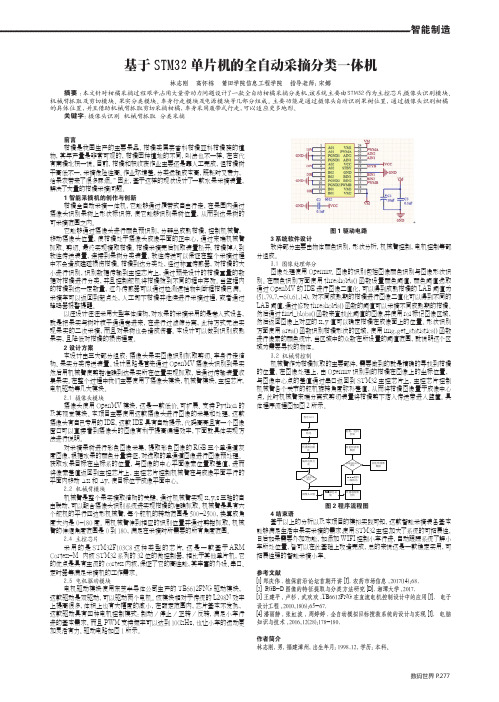
智能制造数码世界 P .277基于STM32单片机的全自动采摘分类一体机林志刚 高怀栋 莆田学院信息工程学院 指导老师:宋娜摘要 :本文针对柑橘采摘过程艰辛,占用大量劳动力问题设计了一款全自动柑橘采摘分类机。
该系统主要由STM32作为主控芯片、摄像头识别模块、机械臂抓取及剪切模块、果实分类模块、车身行走模块及电源模块等几部分组成。
主要功能是通过摄像头自动识别果树位置,通过摄像头识别柑橘的具体位置,并且借助机械臂抓取剪切采摘柑橘,车身采用履带式行走,可以适应更多地形。
关键字:摄像头识别 机械臂抓取 分类采摘前言柑橘是我国生产的主要果品,柑橘类属芸香科柑橘亚科柑橘族的植物,其年产量是非常可观的,柑橘因种植地的不同,叫法也不一样,在古代有南橘北枳一说。
目前,柑橘和枳收获作业主要还是靠人工完成,但柑橘树干高低不一,采摘危险性高、作业环境差,分类运输成本高,既耗时又费力,给果农带来了很多麻烦。
”因此,基于这样的现状设计了一款水果采摘装置,解决了大量的柑橘采摘问题。
1 智能采摘机的创作与创新柑橘全自动采摘一体机,它能够通过履带式自由行走,在果园内通过摄像头识别果树上形状标识符,使它能够识别果树位置,从而到达果树的可采摘范围之内。
它能够通过摄像头进行颜色预识别,分辨出成熟柑橘,控制机械臂,移动摄像头位置,使柑橘处于摄像头成像平面的正中心,通过末端机械臂抓取、剪切、最终实现摘取柑橘。
柑橘采摘完后抓取装置松开,柑橘掉入到软性传送装置,连接到果树分类装置。
软性传送可以保证在整个采摘过程中不会造成磕碰损伤柑橘。
柑橘到达分类处,经过称重传感器,对柑橘的大小进行识别,识别数据传输到主控芯片上,通过预先设计的柑橘重量的数据对柑橘进行分类,并且控制舵机将柑橘拨到不同的框中存放。
当篮框内的柑橘到达一定数量,红外传感器可以通过检测遮挡物判断框柑橘已满。
采摘车可以返回到起点处,人工卸下柑橘并继续进行采摘过程,或者通过蜂鸣器报警提醒。
TL16234+-+MegaPi详细说明+-+V1.0+-+0412

MegaPi说明书(初稿) MegaPi User Manual (First Draft)1、简介IntroductionMegaPi是一款基于ATmega2560的微主控板。
它基于Arduino MEGE 2560,能实现Arduino IDE编程,采用16MHz晶振、USB连接方便下载程序。
它引出了43个输入/输出管脚,15个模拟输入口、3个串口,分成6个功能区域,配合各种功能小模块,可以方便快速的实现多种无线通讯和电机驱动功能,配合多种转接模块可以兼容多种平台电子产品。
并配有2个大功率输出端口,提供最大10A的电流。
MegaPi可以应用于3D 打印机、CNC和各种搭建机器人等复杂功能用途。
可以应用于教育、比赛、娱乐等众多方面。
MegaPi的具有几乎和树莓派一样的大小,3个M4的安装孔方便安装在树莓派上,并通过串口连接,配合相应的程序能快速实现树莓派控制电机、传感器等电子模块等。
MegaPi is microcontroller board based on the ATmega2560. Based on Arduino MEGE 2560, MegaPi also support programming with Arduino IDE. It comes with a 16 MHz crystal oscillator and a USB connector for downloading programs.MegaPi has 43 input/output pins, 15 analog inputs and 3 serial ports. It can be divided into 6 areas according to function. Various function modules can be added to this board to realize wireless communication or to drive motors. With the support of switch modules, MegaPi is also compatible with various electronic products. It has two high-power output interfaces which have a maximum output current of 10A. It is the recommended board for various application scenes, such as 3D printer, CNC and other robotic projects. Moreover, it can also be applied to education, game and entertainment field.MegaPi has the same size as Raspberry Pi. Three mounting holes allow this board to be connected with Raspberry Pi easily. With the support of serial ports and programs, Raspberry Pi then will be capable of driving motors and sensors easily.————小白简介:IntroductionMegaPi是一款针对创客、教育、比赛而推出的高度自由化的开发板,采用Arduino编程,相当于Arduino MEGE 2560,非常容易上手和使用。
恒温NDIR二氧化碳气体传感器研究

第51卷 第2期 激光与红外Vol.51,No.2 2021年2月 LASER & INFRAREDFebruary,2021 文章编号:1001 5078(2021)02 0189 07·红外技术及应用·恒温NDIR二氧化碳气体传感器研究裴 昱1,张加宏1,2,李 敏1,顾 芳1(1 南京信息工程大学电子与信息工程学院,江苏南京210044;2 南京信息工程大学江苏省大气环境与装备技术协同创新中心,江苏南京210044)摘 要:环境温度变化会影响CO2对红外光的吸收效率,为提高非色散红外(NDIR)CO2气体传感器的测量精度,设计了一种基于增量式PID算法的恒温CO2气体传感器系统。
首先利用ANSYSFLUENT软件对恒温控制下的采样气室内部热分布进行模拟仿真,验证了恒温控制的可行性,然后设计了基于PI加热片的恒温控制系统。
实验结果表明,在0~2000ppm气体浓度范围内,本文提出的CO2气体传感器在恒温40℃时的测量误差小于±60ppm,该结果对于研制高性能气体传感器有一定参考价值。
关键词:非色散红外;增量式PID算法;FLUENT仿真;恒温CO2气体传感器中图分类号:TP219;TN219 文献标识码:A DOI:10.3969/j.issn.1001 5078.2021.02.010ResearchonconstanttemperatureNDIRcarbondioxidegassensorPEIYu1,ZHANGJia hong1,2,LIMin1,GUFang1(1.SchoolofElectronicandInformationEngineering,NanjingUniversityofInformationScienceandTechnology,Nanjing210044,China;2.JiangsuCollaborativeInnovationCenteronAtmosphericEnvironmentandEquipmentTechnology,NanjingUniversityofInformationScienceandTechnology,Nanjing210044,China)Abstract:AmbienttemperaturechangeswillaffecttheabsorptionefficiencyofCO2forinfraredlight.Toimprovethemeasurementaccuracyofnon dispersiveinfrared(NDIR)CO2gassensor,aconstanttemperatureCO2gassensorsys tembasedonincrementalPIDalgorithmisdesigned.First,ANSYSFLUENTsoftwarewasappliedtosimulatethether maldistributioninsidethesamplingchamberunderconstanttemperaturecontroltoverifythefeasibilityofconstanttemperaturecontrol.Then,aconstanttemperaturecontrolsystembasedonPIheaterwasdesigned.TheexperimentalresultsshowthatthemeasurementerroroftheCO2gassensorproposedinthispaperataconstanttemperatureof40℃islessthan±60ppmintherangeof0~2000ppmgasconcentration.Thisresulthascertainreferencevalueforthedevelopmentofhigh performancegassensors.Keywords:non dispersiveinfrared;incrementalPIDalgorithm;FLUENTsimulation;constanttemperatureCO2gassensor基金项目:国家自然科学基金项目(No 41605120);江苏高校优势学科Ⅲ期建设工程资助项目(No PAPD)资助。
基于单片机的两轮自平衡车控制系统设计

基于单片机的两轮自平衡车控制系统设计文件排版存档编号:[UYTR-OUPT28-KBNTL98-UYNN208]基于单片机的两轮自平衡车控制系统设计摘要两轮自平衡车是一种高度不稳定的两轮机器人,就像传统的倒立摆一样,本质不稳定是两轮小车的特性,必须施加有效的控制手段才能使其稳定。
本文提出了一种两轮自平衡小车的设计方案,采用重力加速度陀螺仪传感器MPU-6050检测小车姿态,使用互补滤波完成陀螺仪数据与加速度计数据的数据融合。
系统选用STC公司的8位单片机STC12C5A60S2为主控制器,根据从传感器中获取的数据,经过PID算法处理后,输出控制信号至电机驱动芯片TB6612FNG,以控制小车的两个电机,来使小车保持平衡状态。
整个系统制作完成后,小车可以在无人干预的条件下实现自主平衡,并且在引入适量干扰的情况下小车能够自主调整并迅速恢复至稳定状态。
通过蓝牙,还可以控制小车前进,后退,左右转。
关键词:两轮自平衡小车加速度计陀螺仪数据融合滤波 PID算法Design of Control System of Two-Wheel Self-Balance Vehicle based onMicrocontrollerAbstractTwo-wheel self-balance vehicle is a kind of highly unstable two-wheel robot. The characteristic of two-wheel vehicle is the nature of the instability as traditional inverted pendulum, and effective control must be exerted if we need to make it stable. This paper presents a design scheme of two-wheel self-balance vehicle. We need using gravityaccelerometer gyroscope sensor MPU6050 for the inclination angle of vehicle, and using complementary filter for the data fusion of gyroscope and accelerometer. We choose an 8-bit microcontroller named STC12C5A60S2 from STC Company as main controller of the control system. The main controller output control signal, which is based on the data from the sensors, to the motor drive chip named TB6612FNG forcontrolling two motors of vehicle, and keeping the vehicle in balance. After the completion of the control system, the vehicle can achieve autonomous balance under the conditions of unmanned intervention, the vehicle can adjust automatically and restored to a stable statequickly in the case of giving appropriate interference as well. In addition, we can control the vehicle forward, backward and turn around. Key words: Two-Wheel Self-Balance Vehicle; Accelerometer; Gyroscope; Data fusion;Complementary filter; PID algorithm1 绪论自平衡小车的研究背景近几年来,随着电子技术的发展与进步,移动机器人的研究不断深入,成为目前机器人研究领域的一个重要组成部分,并且其应用领域日益广泛,其所需适应的环境和执行的任务也更复杂,这就对移动机器人提出了更高的要求。
智能扫地机器人课程设计
智能扫地机器人课程设计智能扫地机器人课程设计1、课题背景及研究的目的和意义1.1课题背景扫地机器人是服务机器人的一种,可以代替人进行清扫房间、车间、墙壁等。
提出一种应用于室内的移动清洁机器人的设计方案。
其具有实用价值。
室内清洁机器人的主要任务是能够代替人进行清扫,因此需要有一定的智能。
清洁机器人应该具备以下能力:能够自我导航,检测出墙壁,房间内的障碍物并且能够避开;能够走遍房间的大部分空间,可以检测出电池的电量并且能够自主返回充电,同时要求外形比较紧凑,运行稳定,噪音小;要具有人性化的接口,便于操作和控制。
结合扫地机器人主要功能探讨其控制系统的硬件设计。
1.2研究目的和意义国家农业智能装备工程技术研究中心邱权博士说,扫地机器人可以看作是一种智能吸尘器,通过其基于传感器检测的智能运动规划算法使原本由人操作的吸尘器成为一个可自主运行的智能化设备。
它通过各种传感器,比如碰撞开关、红外接近开关、超声传感器、摄像头等,来感知自身的位置和状态,通过智能算法决定当前的任务状态。
它可以根据某个传感器检验地面清洁程度,根据历史信息确定哪些区域已经打扫过,它的充电座会发出红外线信息,在电量低于一定值后,它开始寻找红外信息来自动充电。
防跌落是基于机器人底部所安装的红外传感器检测地面的距离,当距离发生变化时机器人将停止并改变路线。
由于扫地机器人是一个智能化产品,1.3工作原理扫地机器人机身为可移动装置,机器人依托红外识别以及超声波测距从而避障,配合芯片控制内部电机转动以及内部真空环境吸尘,通过路线设计,在室内自由行走,由中央主刷旋转清扫,并且辅以边刷,沿直线或者之字形活动路径打扫。
2、设计要求与内容1)以AT89S52系列单片机为核心设计移动清扫机器人电机驱动与控制电路,采用红外传感器和超声波传感器完成障碍物检测电路设计,完成充电站检测电路设计,完成避障算法与路径规划算法设计。
2)按键选择清扫模式和充电模式。
3)显示方式LED显示当前时间和机器人当前工作状态。
多传感器信息融合的无人车导航系统设计研究

多传感器信息融合的无人车导航系统设计研究摘要:进入21世纪以来,从电子商务平台延伸的快递业蓬勃发展,物流运输中的“最后一公里”问题日益突出。
最后一公里是指物流中心与配送中心之间的距离,是物流配送的最后阶段。
近年来,我国物流总成本占gdp的比重逐年上升,其中“最后一公里”占配送总成本的30%以上。
传统的视觉惯导里程计都会引入累积误差,通常采用回路检测的方法来修正地图的位置和姿态。
然而,在大规模的外部环境中,由于循环中存在大量的状态变量,使得搜索和优化(或过滤)所需的计算资源和计算时间大大增加,导致无法实时建图与定位。
关键词:多传感器信息融合;无人车;导航系统设计引言随着无人驾驶技术的发展和道路试验的成功,无人驾驶配送为物流配送提供了新的解决方案。
近年来,无人物流技术从试验阶段开始进入地面应用阶段,无人机和无人车辆的配送逐渐进入人们的视野。
由于无人机的分布受到诸多限制,在机场自由空间保护区等区域禁止飞行,城市空间飞行受限且高度,受天气影响较大,因此在大风、大雾等恶劣天气下使用的风险非常高。
著名球星科比就是因为在有浓雾的恶劣天气乘直升机出行导致机毁人亡,无人机的分布具有较高的选择性和灵活性。
无人驾驶车辆配送是指无人驾驶车辆装载、通过车辆自主导航系统进行路径规划、将货物运送到指定地点的过程,包括环境感知、导航定位、路径规划和运动控制。
为了实现无人驾驶汽车的自主导航和配送路径的优化,研究配送路径规划算法对节约配送时间、提高配送效率、提高物流服务质量具有重要意义。
1国内外无人车辆物流配送现状与分析目前,国内外无人驾驶汽车分销发展迅速,各大电商物流巨头纷纷推出无人驾驶汽车,交付机器人,在部分道路上进行分布式试验,并在部分特定地区实施着陆应用,在2020年新冠状动脉肺炎期间,未分布式技术已在武汉、景东、百度等企业的地板上得到良好应用。
北京等灾区使用无人驾驶P机分配医疗用品和家电,京东长通车在武汉第九医院24小时内分配医疗用品;阿波罗百度每天按时为北京海淀区一线医务人员提供工作午餐;美国团在北京顺义区推出了无人驾驶卡车,方便了服务区的配送,早在几年前,我国多家企业就进行了无人驾驶飞机配送的研究和测试,2018年,美国小袋完成了在玄辛地区的现场分布测试;在2019年的“818”期间,苏宁推出了“5G沃尔顿”,这款卡车最大的特点是采用了5G技术,更快、更可靠、更快的性能可以实现远程实时监控,应急车辆可以手动操作。
基于树莓派的智能清洁垃圾桶的设计

2023年 / 第8期 物联网技术790 引 言随着社会的发展和科技的进步,环境和资源问题被大多数人所关注,垃圾分类也被提上日程;进一步地,各类智能垃圾桶随着智能科技的发展不断问世。
然而,许多家庭仍在使用传统的垃圾桶。
由于传统垃圾桶位置固定,垃圾桶距离远时扔垃圾不方便,还存在功能单一、无法分类等问题,不能明显提高人们的生活环境和质量,且不利于推动垃圾分类的实施[1-4]。
目前市面上的智能垃圾桶一般只具备单一的配置WiFi 或蓝牙功能,并不能完全从根本上解决原本就存在的问题。
本文所述的智能清洁垃圾桶结合家庭用户及服务行业需求解决了多个有关垃圾桶使用的问题,效率更高,功能更全,更便于实现家庭垃圾分类[5]。
1 总体方案设计本设计以性能强大、模块的拓展性强,以及通过USB串口可以连接多种模块进行操作的树莓派4B 作为系统的主控芯片。
树莓派上运行的ROS 主要作用于智能清洁垃圾桶的数据处理以及指令发布,机身连接着USB 摄像头、麦克风阵列、激光雷达、扬声器。
因为控制左右轮电机采用的是PID 算法,而PID 算法是一种实时性算法,采用严格的实时时钟驱动逻辑,作为上位机的大部分系统满足不了高时效性,所以采用STM32作为本设计的辅助控制芯片,负责指令动作的直接执行,直接驱动左右轮的运作,实现智能清洁垃圾桶的移动、清洁、旋转桶盖等功能[3]。
智能清洁垃圾桶总体由分类垃圾桶、清洁机器人和充电桩这3个部分组成,清洁机器人和分类垃圾桶采用可分离式结构设计,正常模式下作为移动式智能垃圾桶,当用户下达清洁指令后机身分离,清洁机器人脱离分类垃圾桶并记录当前位置执行清洁任务,执行完清洁任务后自动返回合体,并且该智能清洁垃圾桶可以通过手机APP 和电脑远程登录ROS 系统管理和控制。
总体方案设计如图1所示。
2 系统硬件设计系统硬件主要由控制模块、视觉分类模块、运动清洁模块、激光雷达模块、语言交互与声源定位模块组成。
树莓派4B 作为主控单元,通过串口与STM32F103C8T6驱动板通信,调节各个模块之间的运行。
基于语音控制技术的简易智能家居系统设计

• 131•介绍了基于单片机STC15的简易智能家居系统的软硬件设计。
通过XFS5152CE模块实现语音识别和语音播放功能,采用热敏电阻MF52-3950及其相关电路来测量温度,通过12864液晶显示模块来显示系统数据,通过按键来设置温度的阈值,通过继电器等对各种电器设备进行控制,该系统具有一定的实用价值。
1 系统总体结构利用语音识别与控制技术实现对家用电器的控制是智能家居的研究热点。
通过语音控制技术,能够更有效地进行人机通讯,提高家居的便利性。
(贾小龙,基于语音控制技术的智能家居控制系统设计:中国设备工程,2018)这里提出了基于语音识别技术的简易智能家居系统,该系统可以通过语音对各种电器设备进行控制,给家居生活提供更加便利的生活环境。
该系统以STC15为整个系统的核心处理器,通过XFS5152CE模块实现语音识别和语音播放功能。
各种传感器采集环境中的各种状态,如温度、湿度、有害气体浓度等。
STC15负责接收语音识别信息、传感器信息、键盘信息,经过处理,控制各种电器设备。
控制电器设备的方式有多种,本系统实现了通过继电器的开关来控制电器的开关,通过PWM信号来控制风扇的转速。
2 硬件设计本简易智能家居系统采用STC15单片机作为微控制单元,MF52热敏电阻模块组成温度测量电路,单片机读取温度数值,并能通过LCD模块进行温度显示。
用户可以通过键盘模块输入密码及阈值温度,单片机根据当前的温度及阈值温度来控制电机的转速,进而控制风扇的转速。
用户通过语音模块XFS5152CE模块来控制当前系统处于正常运行、暂停或停止状态,同时播报系统所处的状态。
时钟模块用于记录实时时钟,采用PCF8563来实现(图1)。
2.1 单片机控制模块单片机最小系统以STC15W1K16S为核心,并由复位、晶振和电源这三部分电路构成。
STC15W1K16S是宏晶科技公司生产的低电压、高性能CMOS 8位单片机,片内含16KB的可反复擦写的程序存储器和1KB的随机存取数据存储器,采用增强型8051内核,速度比传统8051快7~12倍,采用低功耗设计,有低速模式、空闲模式及掉电模式。
两轮自平衡小车论文

2013年全国大学生电子设计竞赛两轮自平衡小车设计作者:杨魏,黄敏杰,夏俊逸2015.7.17摘要本文采用自制的两轮简易小车作为试验平台,以MEMS传感MPU6050为传感器的姿态感知系统,通过离散卡尔曼滤波器对两种传感器的数据进行滤波融合,选用32位单片机STM32F103RB为控制核心处理器,完成对数据的采集处理和车身控制,采用PID控制算法实现小车两轮自平衡。
用蓝牙控制前后运动。
实验结果验证了该系统的性能满足设计要求。
关键词:两轮自平衡;姿态感知;STM32F103RB;卡尔曼滤波;PID控制。
目录1系统方案 (1)1.1 姿态检测模块的论证与选择 (1)1.2 电机驱动模块的论证与选择 (1)2 系统硬件设计 (1)2.1 STM32F103RB 单片机系统 (2)2.1.1 STM32F103RB 单片机介绍 (2)2.1.2单片机最小系统设计 (3)2.1.3 电源管理模块设计 (4)2.2 姿态检测模块MPU-6050 (5)2.2.1 MPU-6050简介 (5)2.2.3数字运动处理器(DMP) (6)2.3速度检测模块设计 (7)2.3.1编码器介绍 (7)2.3.2 编码器电路设计 (8)2.4 电机驱动模块 (8)2.4.1 L298N简介 (8)2.4.2 L298N特点 (9)3理论分析与计算 (9)3.1 两轮平衡小车数学模型 (9)3.2 PID控制器设计 (10)3.2.1 PID控制器原理 (10)3.2.2 PID控制器设计 (11)3.2.3 PID程序 (12)3.3 基于卡尔曼滤波的数据融合 (13)4 系统软件设计 (15)4.1 系统软件设计框架 (15)4.2 资源模块初始化 (15)4.3 两轮小车姿态信息检测 (16)5测试方案与测试结果 (16)5.1测试方案 (16)5.1.1硬件连接检测 (16)5.1.2小车功能检测 (16)5.2 测试分析与结论 (16)1系统方案本系统主要由姿态检测模块、电机驱动模块、蓝牙模块、红外对管模块、电源模块组成,下面分别论证这几个模块的选择。
- 1、下载文档前请自行甄别文档内容的完整性,平台不提供额外的编辑、内容补充、找答案等附加服务。
- 2、"仅部分预览"的文档,不可在线预览部分如存在完整性等问题,可反馈申请退款(可完整预览的文档不适用该条件!)。
- 3、如文档侵犯您的权益,请联系客服反馈,我们会尽快为您处理(人工客服工作时间:9:00-18:30)。
TB6612FNG模块使用说明
慧净电子
简单说明
•电机电源接口带有反接保护电路.相对于传统的L298N效率上提高很多,体积上也大副减少,当然也就显得更加娇贵,所以我们建议有一定动手能力的朋友使用,接线的时候务必细心细心再细心,本模块全部测试OK才会售出,所以不接受任何形式的退换货,此点不能接受的朋友请慎拍.希望大家理解.
TB6612的的用法
TB6612的的用法:
TB6612是双驱动,也就是可以驱动两个电机
下面分别是控制两个电机的IO口
STBY口接单片机的IO口清零电机全部停止,置1通过AIN1 AIN2,BIN1,BIN2 来控制正反转
VM 接12V以内电源
VCC 接5V电源
GND 就不多说了啊
驱动1路
PWMA 接单片机的PWM口
模块原理图
控制逻辑表
1 TB6612FNG简介
• TB6612FNG是东芝半导体公司生产的一款直流电机驱动器件,它具有大电流MOSFET-H桥结构,双通道电路输出,可同时驱动2个电机。
• TB6612FNG每通道输出最高1 A的连续驱动电流,启动峰值电流达2A/3A(连续脉冲/单脉冲);4种电机控制模式:正转/反转/制动/停止;PWM支持频率高达100 kHz;待机状态;片内低压检测电路与热停机保护电路;工作温度:-20~85℃;SSOP24小型贴片封装。
.
如上图所示,TB6612FNG的主要引脚功能:AINl/AIN2、BIN1/BIN2、PWMA/PWMB为控制信号输入端;AO1/A02、B01/B02为2路电机控制输出端;STBY为正常工作/待机状态控制引脚;VM(3~13.5 V)和VCC(2.7~5.5 V)分别为电机驱动电压输入和逻辑电平输入端。
TB6612FNG是基于MOSFET的H桥集成电路,效率远高于晶体管H桥驱动器。
相比L293D每通道平均600 mA的驱动电流和1.2 A的脉冲峰值电流,它的输出负载能力提高了一倍。
相比L298N的热耗性和外围二极管续流电路,它无需外加散热片,外围电路简单,只需外接电源滤波电容
就可以直接驱动电机,利于减小系统尺寸。
对于PWM信号,高达100 kHz的频率相比以上2款芯片的5 kHz和40 kHz也具有非常大的优势.
Overview
•The TB6612FNG (308k pdf) is a great dual motor driver that is perfect for interfacing two small DC motors such as our micro metal gearmotors to a microcontroller, and it can also be used to control a single bipolar stepper motor. The MOSFET-based H-bridges are much more efficient than the BJT-based H-bridges used in older drivers such as the L298N and Sanyo’s LB1836M, which allows more current to be delivered to the motors and less to be drawn from the logic supply (the LB1836 still has the TB6612 beat for really low-voltage applications). Our little breakout board gives you direct access to all of the features of the TB6612FNG and adds power supply
capacitors and reverse battery protection on the motor supply (note: there is no
reverse protection on the Vcc connection).
•In a typical application, power connections are made on one side of the board and control connections are made on the other. All of the control inputs are internally pulled low. Each of the two motor channels has two direction control pins and a
speed control pin that accepts a PWM input with a frequency of up to 100 kHz.
TheSTBYpin must be driven high to take the driver out of standby mode.
TB6612 Specifications •Recommended motor voltage (VMOT): 4.5 – 13.5 V
•Logic voltage (VCC): 2.7 – 5.5 V
•Output current maximum: 3 A per channel
•Output current continuous: 1 A per channel (can be paralleled to deliver 2 A continuous)
•Maximum PWM frequency: 100 kHz
•Built-in thermal shutdown circuit
•Filtering capacitors on both supply lines
•Reverse-power protection on the motor supply
Real-world power dissipation
considerations
•The TB6612 motor driver used on the carrier board has a peak current rating of 3 A per channel. The peak ratings are for quick transients (e.g. when a motor is first turned on), and the continuous rating of 1 A is dependent on various conditions, such as the ambient temperature. The actual current you can deliver will depend on how well you can keep the motor driver cool. The carrier’s printed circuit board is designed to draw heat out of the motor driver chip, but performance can be improved by adding a heat sink.。
