HSRP实验过程及报告
11-网关冗余HSRP协议-实验报告
–R3(config)#interface Serial0/0/1
–R3(config-if)#ip address 192.168.23.3 255.255.255.0
–R3(config)#router rip
4.配置HSRP
5.检查、测试HSRP
R1HSRP
R3 HSRP
•更改PC0的网关为192.168.13.254,去ping PC1(截图粘贴到实验报告)能否ping通?
R3成为了活动路由器(截图粘贴到实验报告
五实验总结:
1.本次实验很成功,但是在课堂上没能当时完成,课后花费了好多时间,不是一次完成的。但总体收获很大。基本上理解了HSRP的工作原理,也初步掌握了HSRP的配置。
–R2(config)#int g0/0
–R2(config-if)#ip address 192.168.20.2 255.255.255.0
–R2(config)#int s0/0/0
–R2(config-if)#clock rate 128000
–R2(config-if)#ip address 192.168.12.2 255.255.255.0
–R3(config-router)#network 192.168.23.0
–R3(config-router)#network 192.168.13.0
–R3(config-router)#passive-interface GigabitEthernet0/0
3.PC0的网关可以选择任一台路由器设置
–R1(config)#router rip
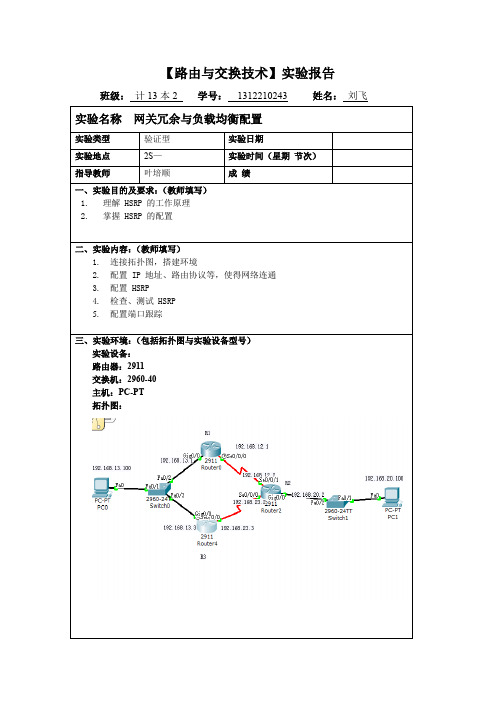
VTP、STP、Port-channel、HSRP综合实验
VTP 、STP 、Port-channel 、HSRP 综合实验实验要求:一、VTP 设置在交换机上启用VTP 协议,三层交换机为Server 模式,二层交换机为Client 模式,并创建四个Vlan ,vlan 10,vlan 20 valan 30,vlan 40二、STP 设置:MSW1设为vlan 10和vlan 20的根网桥,MSW2设为vlan 30和vlan 40的根网桥三、以太网通道Port-channel 设置:MSW1和MSW2交换机上的端口f0/1-2加入channel-group 1成为Port-channel ,并把Port-channel 1设为trunk 模式四、HSRP 热备份路由协议:在两台三层交换机上配置HSRP 或VRRP 协议,为了实现冗余备份和负载均衡,在MSW1上,vlan 10和vlan 20为Active ,vlan 30和vlan 40为Standby ;在MSW2上,vlan 10和vlan 20为Standby ,vlan 30和vlan 40为Activeg ao sh an cn实验步骤:一、 基本配置,配置各端口IP 地址,路由器R1interface Loopback0ip address 1.1.1.1 255.255.255.0 no shutdowninterface Ethernet0/1ip address 192.168.0.1 255.255.255.252 full-duplexinterface Ethernet0/2ip address 192.168.0.5 255.255.255.252 full-duplex交换机MSW1:interface FastEthernet0/0 no switchportip address 192.168.0.2 255.255.255.252 交换机MSW2:interface FastEthernet0/0 no switchportip address 192.168.0.6 255.255.255.252 二,在交换机上配置VTP 协议配置VTP 协议前,需要将相连的交换机之间直连的端口设置为trunk 模式,且vtp domain 必须相同,才可以交流vtp 信息 MSW1(config)#interface fastEthernet 0/3MSW1(config-if)#switchport trunk encapsulation dot1q MSW1(config-if)#switchport mode trunk交换机MSW1:MSW1(config)#vtp domain test MSW1(config)#vtp mode server MSW1(config)#vtp pruningMSW1(config)#vtp password 123456 MSW1(config)#vtp v2-mode交换机MSW2MSW2#vlan databaseMSW2(vlan)# vtp domain test MSW2(vlan)# vtp mode server MSW2(vlan)# vtp pruningMSW2(vlan)# vtp password 123456 MSW2(vlan)# vtp v2-modeg ao sh an cn交换机2SW1:2SW1(config)#vtp domain test2SW1(config)#vtp mode client2SW1(config)#vtp pruning2SW1(config)#vtp password 1234562SW1(config)#vtp v2-mode其它二层交换机配置同2SW1验证VTP:ncnahsoag三,在三层交换机上配置STP 协议MSW1设为vlan 10和vlan 20的根网桥, MSW2设为vlan 30和vlan 40的根网桥MSW1(config)#spanning-tree vlan 10 root primary MSW1(config)#spanning-tree vlan 20 root primary MSW1(config)#spanning-tree vlan 30 root secondary MSW1(config)#spanning-tree vlan 40 root secondaryMSW2(config)#spanning-tree vlan 10 root secondary MSW2(config)#spanning-tree vlan 20 root secondary MSW2(config)#spanning-tree vlan 30 root primary MSW2(config)#spanning-tree vlan 40 root primary 以上配置在running-config 文件中的效果为:在配置生成树协议时,也可以直接指定vlan 的优先级priorityg ao sh an cn验证STP配置,在非根桥交换机上查看端口的转发或阻塞状态ncnahsoag四,在三层交换机之间配置Port-channel 接口MSW1(config)#int range f0/1 -2MSW1(config-if-range)#channel-group 1 mode onMSW1(config)#interface port-channel 1MSW1(config-if)#switchport trunk encapsulation dot1q MSW1(config-if)#switchport mode trunk在对端MSW2上也做相同的配置后,验证如下图:g ao sh an cn五,在两三层交换机之上配置HRRP 或协议 为了实现冗余备份和负载均衡,在MSW1上,设置vlan 10和vlan 20为Active ,vlan 30和vlan 40为Standby ; int vlan 10standby ip 192.168.1.254 standby priority 120 standby preempt#占先权,配置此命令后,当路由器发现本机优先级比现任同一standby 组中的Active 路由器高时,则本机将成为ACTIVE ,当前ACTIVE 路由顺则降为Standby standby track f0/0 50#端口跟踪,当发现跟踪端口Down 时,本路由器standby priority 自动降低50 int vlan 20standby ip 192.168.2.254 standby priority 120 standby preempt standby track f0/0 50 int vlan 30standby ip 192.168.3.254standby priority 100 #在交换机上默认优先级为100,此命令可省 standby preempt#在Standby 网段也需要配置占先权,目的是为了当Active 路由器Down 掉时,本路由器能够迅速由Standby 成为Active int vlan 40standby ip 192.168.4.254 standby preempt在MSW2上,设置vlan 10和vlan 20为Standby ,vlan 30和vlan 40为Activeint vlan 10standby ip 192.168.1.254 standby preempt int vlan 20standby ip 192.168.2.254 standby preempt int vlan 30standby ip 192.168.3.254 standby priority 120 standby preempt standby track f0/0 50 int vlan 40standby ip 192.168.4.254 standby priority 120 standby preempt standby track f0/0 50g ao sh an cn在三层交换机上查看HSRP 的配置结果在MSW1交换机上,vlan10 和vlan 20的虚拟网关为ACTIVE 状态, vlan30 和vlan 40的虚拟网关为STANDBY 状态在MSW2交换机上,vlan10 和vlan 20的虚拟网关为STANDBY 状态, vlan30 和vlan 40的虚拟网关为ACTIVE 状态g ao sh an cn故障验证,将MSW1交换机上的f0/0设为Down 状态时在三层交换MSW1上,当发现f0/0端口DOWN 掉时,由于配置了端口跟踪,vlan 10和vlan 20 的备份优先级自动降低50,由120降为70,低于MSW2上的默认优先级100,虚拟网关由ACTIVE 成为STANDBY 状态与此同时,MSW2交换机发现本机上vlan 10和vlan 20的备份组优先级100高于MSW1上的备份组优先级70,通过占先权抢夺,在MSW2上,vlan 10和vlan 20的备份组状态由STANDBY 变成ACTIVE 。
网络设备安装与调试chp28HSRP和VRRP_28.2HSRP高级配置实验指导
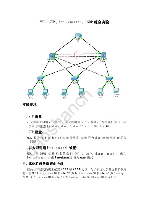
HSRP高级配置1. 实验目的通过本实验,读者可以掌握如下技能:(1)理解HSRP的深入工作原理(2)掌握HSRP的高级配置2. 实验拓扑拓扑图路由器上和三层交换机上都可以配置HSRP,这里是在路由器上配置。
3. 实验步骤(1)配置端口跟踪按照HSPR基本的配置,如果R1的s0/0/0接口出现问题,R1将没有到达R2的Loopback0接口所在网段的路由。
然而R1和R3之间的以太网仍然没有问题,HSRP的Hello包正常发送和接收。
因此R1仍然是虚拟网关192.168.13.254的活动路由器,Server的数据会发送给R1,这样会造成Server无法ping通R2的Loopback0接口。
我们可以配置端口跟踪解决这个问题,端口跟踪使得R1发现s0/0/0上的链路出现问题后,把自己的优先级(我们设为了120)减去一个数字(例如30),成为了90。
由于R3的优先级为默认值100,R3就成为了活动路由器。
配置如下:R1(config)#int f0/0R1(config-if)#standby 1 track s0/0/0 30//以上表明跟踪的是s0/0/0接口,如果该接口故障,优先级降低30,变为120-30=90,这时R3的优先级为100(默认值),因此R3会成为活动路由器,Server数据包将发往R3。
降低的值应该选取合适的值,使得其它路由器能成为活动路由器。
按照步骤3测试HSRP的端口跟踪是否生效。
(2)配置多个HSRP组之前的步骤已经虚拟了192.168.13.254网关,对于这个网关只能有一个活动路由器,于是这个路由器将承担全部的数据流量。
我们可以又创建一个HSRP组,虚拟出另一个网关192.168.13.253,这时R3是活动路由器,让一部分计算机指向这个网关。
这样就能做到负载平衡。
以下是有2个HSRP组的完整配置:R1上:interface FastEthernet0/0standby 1 ip 192.168.13.254standby 1 priority 120standby 1 preemptstandby 1 authentication md5 key-string ciscostandby 1 track Serial0/0/0 30standby 2 ip 192.168.13.253standby 2 preemptstandby 2 authentication md5 key-string ciscoR3上:interface FastEthernet0/0standby 1 ip 192.168.13.254standby 1 preemptstandby 1 authentication md5 key-string ciscostandby 2 ip 192.168.13.253standby 2 priority 120standby 2 preemptstandby 2 authentication md5 key-string ciscostandby 2 track Serial0/0/1 304. 实验调试R1#show standby briefP indicates configured to preempt.|Interface Grp Pri P State Active Standby Virtual IPFa0/0 1 120 P Active local 192.168.13.3 192.168.13.254 //以上表明R1的f0/0接口在HSRP组1中,当前是活动路由器,备份路由器为192.168.13.3,虚拟IP是192.168.13.254。
HSRP实验
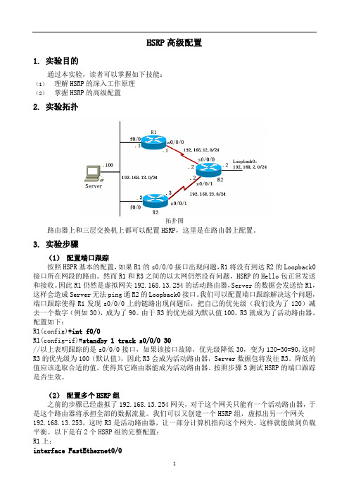
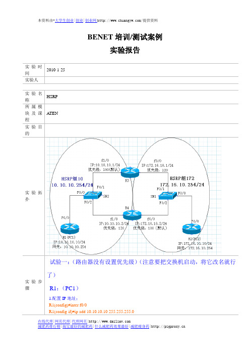
HSRP 一网络拓扑图二实验思路1.vlan trunk 的配置2.ip地址配置3.DHCP DHCP中继配置4.HSRP配置三实验步骤ESW3的基本步骤ESW3#vlan databaseESW3(vlan)#vlan 10VLAN 10 modified:ESW3(vlan)#vlan 20VLAN 20 modified:ESW3(vlan)#vlan 30VLAN 30 modified:ESW3(vlan)#vlan 40VLAN 40 modified:ESW3(vlan)#exitESW3#configESW3(config)#interface f1/0ESW3(config-if)#switchport mode access ESW3(config-if)#switchport access vlan 10 ESW3(config-if)#interface f1/1ESW3(config-if)#switchport mode access ESW3(config-if)#switchport access vlan 20 ESW3(config-if)#interface f1/2ESW3(config-if)#switchport mode access ESW3(config-if)#switchport access vlan 30 ESW3(config-if)#interface f1/3ESW3(config-if)#switchport mode accessESW3(config-if)#switchport access vlan 40ESW3(config-if)#exitESW3(config)#interface fastEthernet 1/4ESW3(config-if)#switchport trunk encapsulation dot1q ESW3(config-if)#switchport mode trunkESW3(config-if)#interface fastEthernet 1/5ESW3(config-if)#switchport trunk encapsulation dot1q ESW3(config-if)#switchport mode trunkESW1的基本配置ESW1#vlan databaseESW1(vlan)#vlan 10VLAN 10 modified:ESW1(vlan)#vlan 20VLAN 20 modified:ESW1(vlan)#vlan 30VLAN 30 modified:ESW1(vlan)#vlan 40VLAN 40 modified:ESW1(vlan)#exitESW1(config)#interface fastEthernet1/2ESW1(config-if)#ip address 192.168.100.1 255.255.255.0 ESW1(config)#interface fastEthernet 1/0ESW1(config-if)#switchport trunk encapsulation dot1q ESW1(config-if)#switchport mode trunkESW1(config-if)#interface fastEthernet 1/1ESW1(config-if)#switchport trunk encapsulation dot1q ESW1(config-if)#switchport mode trunkESW1(config-if)#exESW1(config)#interface vlan 10ESW1(config-if)#ip address 192.168.10.1 255.255.255.0 ESW1(config-if)#standby 10 ip 192.168.10.254ESW1(config-if)# standby 10 priority 200ESW1(config-if)#standby 10 preemptESW1(config)#interface vlan 20ESW1(config-if)#ip address 192.168.20.1 255.255.255.0 ESW1(config-if)#standby 20 ip 192.168.20.254ESW1(config-if)# standby 20 priority 200ESW1(config-if)#standby 20 preemptESW1(config)#interface vlan 30ESW1(config-if)#ip address 192.168.30.1 255.255.255.0 ESW1(config-if)#standby 30 ip 192.168.30.254ESW1(config-if)#standby 30 priority 150ESW1(config-if)#standby 30 preemptESW1(config)#interface vlan 40ESW1(config-if)#ip address 192.168.40.1 255.255.255.0ESW1(config-if)#standby 40 ip 192.168.40.254 ESW1(config-if)#standby 40 priority 150ESW1(config-if)#standby 40 preemptESW1(config-if)#exESW1(config)#interface vlan 10ESW1(config-if)#ip helper-address 192.168.100.2 ESW1(config)#interface vlan 20ESW1(config-if)#ip helper-address 192.168.100.2 ESW1(config)#interface vlan 30ESW1(config-if)#ip helper-address 192.168.100.2 ESW1(config)#interface vlan 40ESW1(config-if)#ip helper-address 192.168.100.2 ESW2的基本配置ESW2#vlan databaseESW2(vlan)#vlan 10VLAN 10 modified:ESW2(vlan)#vlan 20VLAN 20 modified:ESW2(vlan)#vlan 30VLAN 30 modified:ESW2(vlan)#vlan 40VLAN 40 modified:ESW2(vlan)#exitESW2(config)#interface fastEthernet1/2ESW2(config-if)#ip address 192.168.200.1 255.255.255.0 ESW2(config)#interface fastEthernet 1/0ESW2(config-if)#switchport trunk encapsulation dot1q ESW2(config-if)#switchport mode trunkESW2(config-if)#interface fastEthernet 1/1ESW2(config-if)#switchport trunk encapsulation dot1q ESW2(config-if)#switchport mode trunkESW2(config-if)#exESW2(config)#interface vlan 10ESW2(config-if)#ip address 192.168.10.2 255.255.255.0 ESW2(config-if)#standby 10 ip 192.168.10.254ESW2(config-if)#standby 10 priority 150ESW2(config-if)#standby 10 preemptESW2(config)#interface vlan 20ESW2(config-if)#ip address 192.168.20.2 255.255.255.0 ESW2(config-if)#standby 20 ip 192.168.20.254ESW2(config-if)# standby 20 priority 150ESW2(config-if)#standby 20 preemptESW2(config)#interface vlan 30ESW2(config-if)#ip address 192.168.30.2 255.255.255.0 ESW2(config-if)#standby 30 ip 192.168.30.254ESW2(config-if)#standby 30 priority 200ESW2(config-if)#standby 30 preemptESW2(config)#interface vlan 40ESW2(config-if)#ip address 192.168.40.2 255.255.255.0 ESW2(config-if)#standby 40 ip 192.168.40.254ESW2(config-if)#standby 40 priority 200ESW2(config-if)#standby 40 preemptESW2(config-if)#exESW2(config)#interface vlan 10ESW2(config-if)#ip helper-address 192.168.200.2ESW2(config)#interface vlan 20ESW2(config-if)#ip helper-address 192.168.200.2ESW2(config)#interface vlan 30ESW2(config-if)#ip helper-address 192.168.200.2ESW2(config)#interface vlan 40ESW2(config-if)#ip helper-address 192.168.200.2R1的基本配置R1#configureR1(config)#interface ethernet 0/1R1(config-if)#ip address 192.168.100.2 255.255.255.0 R1(config-if)#no shutdownR1(config-if)#interface ethernet 0/0R1(config-if)#ip address 192.168.200.2 255.255.255.0R1(config-if)#no shutdownR1(config-if)#exitR1(config)#service dhcpR1(config)#ip dhcp pool vlan10R1(dhcp-config)# network 192.168.10.0 255.255.255.0 R1(dhcp-config)#default-router 192.168.10.1R1(dhcp-config)#dns-server 3.3.3.3R1(dhcp-config)#exitR1(config)#ip dhcp pool vlan20R1(dhcp-config)# network 192.168.20.0 255.255.255.0 R1(dhcp-config)#default-router 192.168.20.1R1(dhcp-config)#dns-server 3.3.3.3R1(dhcp-config)#exitR1(config)#ip dhcp pool vlan30R1(dhcp-config)# network 192.168.30.0 255.255.255.0 R1(dhcp-config)#default-router 192.168.30.1R1(dhcp-config)#dns-server 3.3.3.3R1(dhcp-config)#exitR1(config)#ip dhcp pool vlan40R1(dhcp-config)# network 192.168.40.0 255.255.255.0 R1(dhcp-config)#default-router 192.168.40.1R1(dhcp-config)#dns-server 3.3.3.3R1(dhcp-config)#exitR1(config)#ip route 192.168.10.0 255.255.255.0 192.168.100.1 R1(config)#ip route 192.168.10.0 255.255.255.0 192.168.200.1 R1(config)#ip route 192.168.20.0 255.255.255.0 192.168.100.1 R1(config)#ip route 192.168.20.0 255.255.255.0 192.168.200.1 R1(config)#ip route 192.168.30.0 255.255.255.0 192.168.100.1 R1(config)#ip route 192.168.30.0 255.255.255.0 192.168.200.1 R1(config)#ip route 192.168.40.0 255.255.255.0 192.168.100.1 R1(config)#ip route 192.168.40.0 255.255.255.0 192.168.200.1测试结果PC1 DHCP show ipPC1> dhcpDORA IP 192.168.10.2/24 GW 192.168.10.1PC1> show ipNAME : PC1[1]IP/MASK : 192.168.10.2/24GATEWAY : 192.168.10.1DNS : 3.3.3.3DHCP SERVER : 192.168.100.2DHCP LEASE : 86397, 86400/43200/75600MAC : 00:50:79:66:68:00LPORT : 10000RHOST:PORT : 127.0.0.1:10001MTU: : 1500PC2 DHCP show ipPC2> dhcpDORA IP 192.168.20.2/24 GW 192.168.20.1 PC2> show ipNAME : PC2[1]IP/MASK : 192.168.20.2/24 GATEWAY : 192.168.20.1DNS : 3.3.3.3DHCP SERVER : 192.168.100.2DHCP LEASE : 86394, 86400/43200/75600 MAC : 00:50:79:66:68:01LPORT : 10004RHOST:PORT : 127.0.0.1:10005MTU: : 1500PC3 DHCP show ipPC3> dhcpDORA IP 192.168.30.2/24 GW 192.168.30.1PC3> show ipNAME : PC3[1]IP/MASK : 192.168.30.2/24 GATEWAY : 192.168.30.1DNS : 3.3.3.3DHCP SERVER : 192.168.100.2DHCP LEASE : 86393, 86400/43200/75600 MAC : 00:50:79:66:68:02LPORT : 10002RHOST:PORT : 127.0.0.1:10003MTU: : 1500PC4 DHCP show ipPC4> dhcpDORA IP 192.168.40.2/24 GW 192.168.40.1 PC4> show ipNAME : PC4[1]IP/MASK : 192.168.40.2/24 GATEWAY : 192.168.40.1DNS : 3.3.3.3DHCP SERVER : 192.168.100.2DHCP LEASE : 86394, 86400/43200/75600MAC : 00:50:79:66:68:03LPORT : 10006RHOST:PORT : 127.0.0.1:10007MTU: : 1500PC1pingPC4PC1> ping 192.168.40.2 -t84 bytes from 192.168.40.2 icmp_seq=1 ttl=63 time=37.786 ms 84 bytes from 192.168.40.2 icmp_seq=2 ttl=63 time=31.251 ms 84 bytes from 192.168.40.2 icmp_seq=3 ttl=63 time=37.749 ms 84 bytes from 192.168.40.2 icmp_seq=4 ttl=63 time=15.626 ms 84 bytes from 192.168.40.2 icmp_seq=5 ttl=63 time=31.264 ms当f1/0接口关闭之后192.168.40.2 icmp_seq=6 timeout192.168.40.2 icmp_seq=7 timeout84 bytes from 192.168.40.2 icmp_seq=8 ttl=63 time=31.251 ms 84 bytes from 192.168.40.2 icmp_seq=9 ttl=63 time=37.282 ms 84 bytes from 192.168.40.2 icmp_seq=10 ttl=63 time=84.531 ms 84 bytes from 192.168.40.2 icmp_seq=11 ttl=63 time=31.253 ms84 bytes from 192.168.40.2 icmp_seq=12 ttl=63 time=31.250 ms 84 bytes from 192.168.40.2 icmp_seq=13 ttl=63 time=122.337 ms 84 bytes from 192.168.40.2 icmp_seq=14 ttl=63 time=31.248 ms五调试信息ESW1 show running-configESW1#show running-configBuilding configuration...Current configuration : 2971 bytes!version 12.3service timestamps debug datetime msecservice timestamps log datetime msecno service password-encryption!hostname ESW1!boot-start-markerboot-end-marker!!no aaa new-modelresource policy!memory-size iomem 5ip subnet-zerono ip icmp rate-limit unreachable ip tcp synwait-time 5!!ip cefno ip domain lookupno ip dhcp use vrf connected!!!!!!!!!!!!!!!vtp file nvram:vlan.dat!!no crypto isakmp ccm!!!!interface FastEthernet1/0 switchport mode trunkduplex fullspeed 100!interface FastEthernet1/1 switchport mode trunkduplex fullspeed 100interface FastEthernet1/2no switchportip address 192.168.100.1 255.255.255.0 duplex fullspeed 100!interface FastEthernet1/3duplex fullspeed 100!interface FastEthernet1/4duplex fullspeed 100!interface FastEthernet1/5duplex fullspeed 100!interface FastEthernet1/6duplex fullspeed 100!interface FastEthernet1/7 duplex fullspeed 100!interface FastEthernet1/8 duplex fullspeed 100!interface FastEthernet1/9 duplex fullspeed 100!interface FastEthernet1/10 duplex fullspeed 100!interface FastEthernet1/11 duplex fullspeed 100!interface FastEthernet1/12 duplex fullspeed 100interface FastEthernet1/13duplex fullspeed 100!interface FastEthernet1/14duplex fullspeed 100!interface FastEthernet1/15duplex fullspeed 100!interface Vlan1no ip addressshutdown!interface Vlan10ip address 192.168.10.1 255.255.255.0 ip helper-address 192.168.100.2standby 10 ip 192.168.10.254standby 10 priority 200standby 10 preemptinterface Vlan20ip address 192.168.20.1 255.255.255.0 ip helper-address 192.168.100.2standby 20 ip 192.168.20.254standby 20 priority 200standby 20 preempt!interface Vlan30ip address 192.168.30.1 255.255.255.0 ip helper-address 192.168.100.2standby 30 ip 192.168.30.254standby 30 priority 150standby 30 preempt!interface Vlan40ip address 192.168.40.1 255.255.255.0 ip helper-address 192.168.100.2standby preemptstandby 40 ip 192.168.40.254standby 40 priority 150!no ip http serverno ip http secure-serverip classless!!!no cdp log mismatch duplex!!!control-plane!!!!!!!!!banner exec ^C************************************************************* **This is a normal Router with a SW module inside (NM-16ESW)It has been preconfigured with hard coded speed and duplexTo create vlans use the command "vlan database" from exec mode After creating all desired vlans use "exit" to apply the configTo view existing vlans use the command "show vlan-switch brief"Warning: You are using an old IOS image for this router. Please update the IOS to enable the "macro" command!************************************************************* **^C!line con 0exec-timeout 0 0privilege level 15logging synchronousline aux 0exec-timeout 0 0privilege level 15logging synchronousline vty 0 4login!!endESW2 show running-configESW2#show running-configBuilding configuration...Current configuration : 3130 bytes!version 12.3service timestamps debug datetime msec service timestamps log datetime msec no service password-encryption!hostname ESW2!boot-start-markerboot-end-marker!!no aaa new-modelresource policy!memory-size iomem 5ip subnet-zerono ip icmp rate-limit unreachable ip tcp synwait-time 5!!ip cefno ip domain lookupno ip dhcp use vrf connected!!!!!!!!!!!!!!!vtp file nvram:vlan.dat!!no crypto isakmp ccm!!!!interface FastEthernet1/0 switchport mode trunkduplex fullspeed 100!interface FastEthernet1/1 switchport mode trunkduplex fullspeed 100interface FastEthernet1/2no switchportip address 192.168.200.1 255.255.255.0 duplex fullspeed 100!interface FastEthernet1/3duplex fullspeed 100!interface FastEthernet1/4duplex fullspeed 100!interface FastEthernet1/5duplex fullspeed 100!interface FastEthernet1/6duplex fullspeed 100!interface FastEthernet1/7 duplex fullspeed 100!interface FastEthernet1/8 duplex fullspeed 100!interface FastEthernet1/9 duplex fullspeed 100!interface FastEthernet1/10 duplex fullspeed 100!interface FastEthernet1/11 duplex fullspeed 100!interface FastEthernet1/12 duplex fullspeed 100interface FastEthernet1/13duplex fullspeed 100!interface FastEthernet1/14duplex fullspeed 100!interface FastEthernet1/15duplex fullspeed 100!interface Vlan1no ip addressshutdown!interface Vlan10ip address 192.168.10.254 255.255.255.0 ip helper-address 192.168.200.2standby 10 ip 192.168.10.254standby 10 priority 150standby 10 preemptinterface Vlan20ip address 192.168.20.254 255.255.255.0 ip helper-address 192.168.200.2standby 20 ip 192.168.20.254standby 20 priority 150standby 20 preempt!interface Vlan30ip address 192.168.30.254 255.255.255.0 ip helper-address 192.168.200.2standby 30 ip 192.168.30.254standby 30 priority 200standby 30 preempt!interface Vlan40ip address 192.168.40.254 255.255.255.0 ip helper-address 192.168.200.2standby 40 ip 192.168.40.254standby 40 priority 200standby 40 preempt!no ip http serverno ip http secure-serverip classless!!!mac-address-table static 0000.0c07.ac1e interface FastEthernet1/1 vlan 30mac-address-table static 0000.0c07.ac28 interface FastEthernet1/1 vlan 40no cdp log mismatch duplex!!!control-plane!!!!!!!!!banner exec ^C************************************************************* **This is a normal Router with a SW module inside (NM-16ESW)It has been preconfigured with hard coded speed and duplexTo create vlans use the command "vlan database" from exec modeAfter creating all desired vlans use "exit" to apply the config To view existing vlans use the command "show vlan-switch brief"Warning: You are using an old IOS image for this router. Please update the IOS to enable the "macro" command!************************************************************* **^C!line con 0exec-timeout 0 0privilege level 15logging synchronousline aux 0exec-timeout 0 0privilege level 15logging synchronousline vty 0 4login!!endESW3 show running-configESW3#show running-configBuilding configuration...Current configuration : 2415 bytes!version 12.3service timestamps debug datetime msec service timestamps log datetime msec no service password-encryptionno service dhcp!hostname ESW3!boot-start-markerboot-end-marker!!no aaa new-model!resource policy!memory-size iomem 5ip subnet-zerono ip routingno ip icmp rate-limit unreachable ip tcp synwait-time 5!!no ip cefno ip domain lookupno ip dhcp use vrf connected!!!!!!!!!!!!!!!vtp file nvram:vlan.dat!!no crypto isakmp ccm!!!!interface FastEthernet1/0 switchport access vlan 10 duplex fullspeed 100interface FastEthernet1/1 switchport access vlan 20 duplex fullspeed 100!interface FastEthernet1/2 switchport access vlan 30 duplex fullspeed 100!interface FastEthernet1/3 switchport access vlan 40 duplex fullspeed 100!interface FastEthernet1/4 switchport mode trunkduplex fullspeed 100!interface FastEthernet1/5 switchport mode trunkduplex fullspeed 100!interface FastEthernet1/6 duplex fullspeed 100!interface FastEthernet1/7 duplex fullspeed 100!interface FastEthernet1/8 duplex fullspeed 100!interface FastEthernet1/9 duplex fullspeed 100!interface FastEthernet1/10 duplex fullspeed 100!interface FastEthernet1/11 duplex fullspeed 100!interface FastEthernet1/12 duplex fullspeed 100!interface FastEthernet1/13 duplex fullspeed 100!interface FastEthernet1/14 duplex fullspeed 100!interface FastEthernet1/15 duplex fullspeed 100!interface Vlan1no ip addressno ip route-cacheshutdown!no ip http serverno ip http secure-server ip classless!!!no cdp log mismatch duplex !!!control-plane!!!!!!!!!banner exec ^C************************************************************* **This is a normal Router with a SW module inside (NM-16ESW)It has been preconfigured with hard coded speed and duplexTo create vlans use the command "vlan database" from exec modeAfter creating all desired vlans use "exit" to apply the config To view existing vlans use the command "show vlan-switch brief"Warning: You are using an old IOS image for this router. Please update the IOS to enable the "macro" command!************************************************************* **^C!line con 0exec-timeout 0 0privilege level 15logging synchronousline aux 0exec-timeout 0 0privilege level 15logging synchronousline vty 0 4login!!endR1 show running-configR1#show running-configBuilding configuration...Current configuration : 2114 bytes!version 12.3service timestamps debug datetime msec service timestamps log datetime msec no service password-encryption!hostname R1!boot-start-markerboot-end-marker!!no aaa new-model!resource policy!memory-size iomem 5ip subnet-zerono ip icmp rate-limit unreachableip tcp synwait-time 5!!ip cefno ip domain lookupno ip dhcp use vrf connected!ip dhcp pool vlan10network 192.168.10.0 255.255.255.0 default-router 192.168.10.1dns-server 3.3.3.3!ip dhcp pool vlan20network 192.168.20.0 255.255.255.0 default-router 192.168.20.1dns-server 3.3.3.3!ip dhcp pool vlan30network 192.168.30.0 255.255.255.0 default-router 192.168.30.1dns-server 3.3.3.3!ip dhcp pool vlan40network 192.168.40.0 255.255.255.0 default-router 192.168.40.1dns-server 3.3.3.3!!!!!!!!!!!!!!!!!no crypto isakmp ccm!!!!interface Ethernet0/0ip address 192.168.200.2 255.255.255.0 half-duplex!interface Ethernet0/1ip address 192.168.100.2 255.255.255.0 half-duplex!interface Ethernet0/2no ip addressshutdownhalf-duplexinterface Ethernet0/3 no ip addressshutdownhalf-duplex!interface Ethernet1/0 no ip addressshutdownhalf-duplex!interface Ethernet1/1 no ip addressshutdownhalf-duplex!interface Ethernet1/2 no ip addressshutdownhalf-duplex!interface Ethernet1/3 no ip addressshutdownhalf-duplex!no ip http serverno ip http secure-serverip classlessip route 192.168.10.0 255.255.255.0 192.168.100.1 ip route 192.168.10.0 255.255.255.0 192.168.200.1 ip route 192.168.20.0 255.255.255.0 192.168.100.1 ip route 192.168.20.0 255.255.255.0 192.168.200.1 ip route 192.168.30.0 255.255.255.0 192.168.100.1 ip route 192.168.30.0 255.255.255.0 192.168.200.1 ip route 192.168.40.0 255.255.255.0 192.168.100.1 ip route 192.168.40.0 255.255.255.0 192.168.200.1 !!!no cdp log mismatch duplex!!!control-plane!!!!!!!!!!line con 0exec-timeout 0 0privilege level 15 logging synchronous line aux 0exec-timeout 0 0privilege level 15 logging synchronous line vty 0 4login!!end六实验结论通过这系列实验,熟悉了HSRP的协议,加深了理解。
在思科模拟器Packet Tracer中实现HSRP热备份路由实验

在思科模拟器Packet Tracer中实现HSRP 热备份路由实验作者:刘侃来源:《电脑知识与技术》2019年第13期摘要:基于对计思科HSRP 热备份路由协议的研究,探讨如何利用HSRP 的高可靠性特点,组建具有低故障率和高稳定性和企业局域网。
通过分析HSRP 网络结构、工作过程和网络设备的配置等方面内容,阐述了热备份路由器的工作原理、优势及配置过程,对于企业、学校等单位中心机房核心层的建设具有一定的参考价值。
关键词:HSRP;热备份;三层交换机;路由器;Packet Tracer中图分类号:TP3 ; ; ; ;文献标识码:A文章编号:1009-3044(2019)13-0048-02当下信息技术已渗透到企业办公、生产、管理各个环节,各种信息系统得到广泛的应用,这对网络的稳定性提出了更高的要求,所以承载这些信息系统的局域网络必须拥有低故障率和高稳定性,要实现这样的目标,必须合理地规划网络拓扑。
对核心层设备采用热备份可以大幅度提高网络可靠性,思科的HSRP协议正是这样一种3层冗余协议,它能实现在一个路由器失效的情况下,其全部任务可以被另一个备份路由器完全接管,使得网络通迅不会因为某个路由器的失效而中断,Packet Tracer模拟器可实现此实验。
1 HSRP相关概念HSPR(热备份路由协议)是思科私有协议,又称为第一跳冗余协议,能防止路由器单点失效而导致的网络故障。
HSRP协议要求至少有两台以上的路由器,这些路由器组成一个HSRP组,我们称之为“热备份组”,每个组生成一个虚拟路由器。
在任何时候,每个组内只有一活动(Active)路由器,数据包只能由活动路由器转发,如果该设备发生了故障,备份路由器将取而代之成为新的活动路由器,切换速度迅捷,所以网络内主机仍然保持连接,没有受到故障过多的影响。
要完成HSRP热备份路由配置,需了解一些基本概念。
1)虚拟路由器HSRP的虚拟路由器包含一个虚拟IP地址,以及虛拟的MAC地址。
HSRP实验文档

HSRP热备份实验小组成员:赵鹏飞、李阳、张业萌、文秀柱袁泽龙、谭璐、刘鉴滢、马振昊一、需求分析 (3)1. 应用背景 (3)2. 用户需求 (3)二、设计分析 (4)1.实验分析 (4)2.规划后的新的拓扑图如下: (4)三、 IP规划 (4)四、使用技术 (5)1. 热备份简介 (5)2. 本协议的特点 (5)五、设备选型 (6)1.设备选购 (6)2.设备清单 (7)六、配置步骤 (7)1.RS1配置如下: (7)2.RS2配置如下: (8)3.检查是否配置成功 (8)4.测试结果 (9)七、综述方案特点 (11)一、需求分析1. 应用背景随着Internet的日益普及,人们对网络的依赖性也越来越强。
这同时对网络的稳定性提出了更高的要求,人们自然想到了基于设备的备份结构,就像在服务器中为提高数据的安全性而采用双硬盘结构一样。
路由器是整个网络的核心和心脏,如果路由器发生致命性的故障,将导致本地网络的瘫痪,如果是骨干路由器,影响的范围将更大,所造成的损失也是难以估计的。
因此,对路由器采用热备份是提高网络可靠性的必然选择。
在一个路由器或交换机完全不能工作的情况下,它的全部功能便被系统中的另一个备份路由器或交换机完全接管,直至出现问题的路由器或交换机恢复正常,这就是热备份路由协议(HotStandbyRouterProtocal),HSR PRFC2281技术要解决的问题。
2. 用户需求拓扑图如下:要求:正常情况下S1下连的所有PC通过RS1连接Internet,S2下连的所有PC通过RS2连接Internet.当链路出现故障时,PC通过所连的另一线路连接Intenet二、 设计分析1.实验分析首先将23\24端口激活为三层端口,然后配上相应IP,然后,Group 10虚拟IP 为192.168.1.3, Group 20虚拟IP 为192.168.2.3,并把各端口设为抢占模式.对于RS1,将24端口加入Group 10,优先级为20, 将23端口加入Group 20, 优先级为10,; 对于RS2,将24端口加入Group 20, 优先级为20,将23端口加入Group 10,优先级为10.2.规划后的新的拓扑图如下:三、 IP 规划设备 IP 端口 与S1连接的端口 与S2连接的端口RS1 192.168.1.1 24 24192.168.2.1 23 23 RS2 192.168.1.2 23 23192.168.2.2 24 24 四、使用技术使用热备份协议完成需求1. 热备份简介HSRP:热备份路由器协议(HSRP:Hot Standby Router Protocol)热备份路由器协议(HSRP)的设计目标是支持特定情况下IP 流量失败转移不会引起混乱、并允许主机使用单路由器,以及即使在实际第一跳路由器使用失败的情形下仍能维护路由器间的连通性。
STP和EtherChannel 及部署HSRP三个实验文档
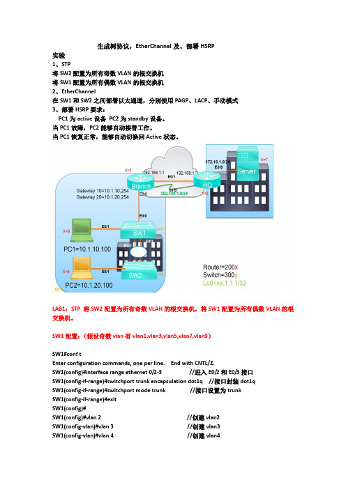
生成树协议,EtherChannel及、部署HSRP实验1、STP将SW2配置为所有奇数VLAN的根交换机将SW1配置为所有偶数VLAN的根交换机2、EtherChannel在SW1和SW2之间部署以太通道,分别使用PAGP、LACP、手动模式3、部署HSRP要求:PC1为active设备PC2为standby设备。
当PC1故障,PC2能够自动接替工作。
当PC1恢复正常,能够自动切换回Active状态。
LAB1:STP 将SW2配置为所有奇数VLAN的根交换机,将SW1配置为所有偶数VLAN的根交换机。
SW1配置:(假设奇数vlan有vlan1,vlan3,vlan5,vlan7,vlan9)SW1#conf tEnter configuration commands, one per line. End with CNTL/Z.SW1(config)#interface range ethernet 0/2-3 //进入E0/2和E0/3接口SW1(config-if-range)#switchport trunk encapsulation dot1q //接口封装dot1qSW1(config-if-range)#switchport mode trunk //接口设置为trunkSW1(config-if-range)#exitSW1(config)#SW1(config)#vlan 2 //创建vlan2SW1(config-vlan)#vlan 3 //创建vlan3SW1(config-vlan)#vlan 4 //创建vlan4SW1(config-vlan)#vlan 5 //创建vlan5SW1(config-vlan)#vlan 6 //创建vlan6SW1(config-vlan)#vlan 7 //创建vlan7SW1(config-vlan)#vlan 8 //创建vlan8SW1(config-vlan)#vlan 9 //创建vlan9SW1(config-vlan)#vlan 10 //创建vlan10SW1(config-vlan)#exitSW1(config)#spanning-tree mode mst //设置spanning-tree模式为mst SW1(config)#spanning-tree mst configuration //进入mst配置SW1(config-mst)#instance 1 vlan 1,3,5,7,9 //设置实例instance 1 关联奇数vlan SW1(config-mst)#instance 2 vlan 2,4,6,8,10 //设置实例instance 2关联奇数vlan SW1(config-mst)#name cisco //设置域名SW1(config-mst)#revision 1 //设置修订号SW1(config-mst)#exitSW1(config)#spanning-tree mst 1 root primary //设置mst 1本交换机的为根交换机SW1(config)#SW2配置:(假设偶数vlan有vlan2,vlan4,vlan6,vlan8.vlan10)SW2#conf tEnter configuration commands, one per line. End with CNTL/Z.SW2(config)#interface range ethernet 0/2-3 //进入E0/2和E0/3接口SW2(config-if-range)#switchport trunk encapsulation dot1q //接口封装dot1qSW2(config-if-range)#switchport mode trunk //接口设置为trunkSW2(config-if-range)#exitSW2(config)#SW2(config)#vlan 2 //创建vlan2SW2(config-vlan)#vlan 3 //创建vlan3SW2(config-vlan)#vlan 4 //创建vlan4SW2(config-vlan)#vlan 5 //创建vlan5SW2(config-vlan)#vlan 6 //创建vlan6SW2(config-vlan)#vlan 7 //创建vlan7SW2(config-vlan)#vlan 8 //创建vlan8SW2(config-vlan)#vlan 9 //创建vlan9SW2(config-vlan)#vlan 10 //创建vlan10SW2(config-vlan)#exitSW2(config)#spanning-tree mode mst //设置spanning-tree模式为mst SW2(config)#spanning-tree mst configuration //进入mst配置SW2(config-mst)#instance 1 vlan 1,3,5,7,9 //设置实例instance 1 关联奇数vlan SW2(config-mst)#instance 2 vlan 2,4,6,8,10 //设置实例instance 2关联奇数vlan SW2(config-mst)#name cisco //设置域名SW2(config-mst)#revision 1 //设置修订号SW2(config-mst)#exitSW2(config)#spanning-tree mst 2 root primary //设置mst 2本交换机的为根交换机SW2(config)#结果查看:LAB2: EtherChannel 在SW1和SW2之间部署以太通道,分别使用PAGP、LACP、手动模式.SW1配置:(手动模式)SW1>enable //用户模式进入到特权模式SW1#configure terminal //特权模式进入到全局配置模式Enter configuration commands, one per line. End with CNTL/Z.SW1(config)#interface range ethernet 0/2-3 //进入接口E0/2和E0/3SW1(config-if-range)#switchport trunk encapsulation dot1q //接口封装dot1qSW1(config-if-range)#switchport mode trunk //接口模式设置为trunkSW1(config-if-range)#shutdown //关闭接口SW1(config-if-range)#*Oct 27 17:19:17.164: %LINK-5-CHANGED: Interface Ethernet0/2, changed state toadministratively down*Oct 27 17:19:17.165: %LINK-5-CHANGED: Interface Ethernet0/3, changed state to administratively down*Oct 27 17:19:18.165: %LINEPROTO-5-UPDOWN: Line protocol on Interface Ethernet0/2, changed state to down*Oct 27 17:19:18.165: %LINEPROTO-5-UPDOWN: Line protocol on Interface Ethernet0/3, changed state to downSW1(config-if-range)#channel-group 6 mode on //手动开启channel通道Creating a port-channel interface Port-channel 6SW1(config-if-range)#no shutdown //开启接口SW1(config-if-range)#*Oct 27 17:19:51.060: %LINK-3-UPDOWN: Interface Ethernet0/2, changed state to up*Oct 27 17:19:51.060: %LINK-3-UPDOWN: Interface Ethernet0/3, changed state to upSW1(config-if-range)#*Oct 27 17:19:53.076: %LINEPROTO-5-UPDOWN: Line protocol on Interface Ethernet0/2, changed state to up*Oct 27 17:19:53.076: %LINEPROTO-5-UPDOWN: Line protocol on Interface Ethernet0/3, changed state to upSW1(config-if-range)#*Oct 27 17:19:55.080: %LINEPROTO-5-UPDOWN: Line protocol on Interface Port-channel6, changed state to upSW1(config-if-range)#SW2配置:(手动模式)SW2>enable //用户模式进入到特权模式SW2#configure terminal //特权模式进入到全局配置模式Enter configuration commands, one per line. End with CNTL/Z.SW2(config)#interface range ethernet 0/2-3 //进入接口E0/2和E0/3SW2(config-if-range)#switchport trunk encapsulation dot1q //接口封装dot1qSW2(config-if-range)#switchport mode trunk //接口模式设置为trunkSW2(config-if-range)#shutdown //关闭接口SW2(config-if-range)#*Oct 27 17:17:31.191: %LINK-5-CHANGED: Interface Ethernet0/2, changed state to administratively down*Oct 27 17:17:31.191: %LINK-5-CHANGED: Interface Ethernet0/3, changed state to administratively down*Oct 27 17:17:32.195: %LINEPROTO-5-UPDOWN: Line protocol on Interface Ethernet0/2, changed state to down*Oct 27 17:17:32.195: %LINEPROTO-5-UPDOWN: Line protocol on Interface Ethernet0/3, changed state to downSW2(config-if-range)#channel-group 6 mode on //手动开启channel通道Creating a port-channel interface Port-channel 6SW2(config-if-range)#no shutdown //开启接口*Oct 27 17:19:57.829: %LINK-3-UPDOWN: Interface Ethernet0/2, changed state to up*Oct 27 17:19:57.829: %LINK-3-UPDOWN: Interface Ethernet0/3, changed state to up*Oct 27 17:19:58.835: %LINEPROTO-5-UPDOWN: Line protocol on Interface Ethernet0/2, changed state to up*Oct 27 17:19:58.836: %LINEPROTO-5-UPDOWN: Line protocol on Interface Ethernet0/3, changed state to upSW2(config-if-range)#*Oct 27 17:20:01.829: %LINEPROTO-5-UPDOWN: Line protocol on Interface Port-channel6, changed state to upSW2(config-if-range)#etherchannel通道查看:SW1和SW2配置(PAGP模式)SW1配置:SW1>enable //用户模式进入到特权模式SW1#configure terminal //特权模式进入到全局配置模式Enter configuration commands, one per line. End with CNTL/Z.SW1(config)#interface range ethernet 0/2-3 //进入接口E0/2和E0/3SW1(config-if-range)#switchport trunk encapsulation dot1q //接口封装dot1qSW1(config-if-range)#switchport mode trunk //接口模式设置为trunkSW1(config-if-range)#shutdown //关闭接口SW1(config-if-range)#*Oct 27 17:19:17.164: %LINK-5-CHANGED: Interface Ethernet0/2, changed state to administratively down*Oct 27 17:19:17.165: %LINK-5-CHANGED: Interface Ethernet0/3, changed state to administratively down*Oct 27 17:19:18.165: %LINEPROTO-5-UPDOWN: Line protocol on Interface Ethernet0/2, changed state to down*Oct 27 17:19:18.165: %LINEPROTO-5-UPDOWN: Line protocol on Interface Ethernet0/3, changed state to downSW1(config-if-range)#channel-group 8 mode desirable //开启channel通道协商Creating a port-channel interface Port-channel 8SW1(config-if-range)#no shutdown //开启接口SW1(config-if-range)#*Oct 27 17:19:51.060: %LINK-3-UPDOWN: Interface Ethernet0/2, changed state to up*Oct 27 17:19:51.060: %LINK-3-UPDOWN: Interface Ethernet0/3, changed state to upSW1(config-if-range)#*Oct 27 17:19:53.076: %LINEPROTO-5-UPDOWN: Line protocol on Interface Ethernet0/2, changed state to up*Oct 27 17:19:53.076: %LINEPROTO-5-UPDOWN: Line protocol on Interface Ethernet0/3, changed state to upSW1(config-if-range)#*Oct 27 17:19:55.080: %LINEPROTO-5-UPDOWN: Line protocol on Interface Port-channel8, changed state to upSW1(config-if-range)#SW2配置:SW2>enable //用户模式进入到特权模式SW2#configure terminal //特权模式进入到全局配置模式Enter configuration commands, one per line. End with CNTL/Z.SW2(config)#interface range ethernet 0/2-3 //进入接口E0/2和E0/3SW2(config-if-range)#switchport trunk encapsulation dot1q //接口封装dot1qSW2(config-if-range)#switchport mode trunk //接口模式设置为trunkSW2(config-if-range)#shutdown //关闭接口SW2(config-if-range)#*Oct 27 17:17:31.191: %LINK-5-CHANGED: Interface Ethernet0/2, changed state to administratively down*Oct 27 17:17:31.191: %LINK-5-CHANGED: Interface Ethernet0/3, changed state to administratively down*Oct 27 17:17:32.195: %LINEPROTO-5-UPDOWN: Line protocol on Interface Ethernet0/2, changed state to down*Oct 27 17:17:32.195: %LINEPROTO-5-UPDOWN: Line protocol on Interface Ethernet0/3,changed state to downSW2(config-if-range)#channel-group 8 mode desirable //开启channel通道协商Creating a port-channel interface Port-channel 8SW2(config-if-range)#no shutdown //开启接口*Oct 27 17:19:57.829: %LINK-3-UPDOWN: Interface Ethernet0/2, changed state to up*Oct 27 17:19:57.829: %LINK-3-UPDOWN: Interface Ethernet0/3, changed state to up*Oct 27 17:19:58.835: %LINEPROTO-5-UPDOWN: Line protocol on Interface Ethernet0/2, changed state to up*Oct 27 17:19:58.836: %LINEPROTO-5-UPDOWN: Line protocol on Interface Ethernet0/3, changed state to upSW2(config-if-range)#*Oct 27 17:20:01.829: %LINEPROTO-5-UPDOWN: Line protocol on Interface Port-channel8, changed state to upSW2(config-if-range)#结果查看:SW1和SW2配置(LACP模式)SW1配置:SW1>enable //用户模式进入到特权模式SW1#configure terminal //特权模式进入到全局配置模式Enter configuration commands, one per line. End with CNTL/Z.SW1(config)#interface range ethernet 0/2-3 //进入接口E0/2和E0/3SW1(config-if-range)#switchport trunk encapsulation dot1q //接口封装dot1qSW1(config-if-range)#switchport mode trunk //接口模式设置为trunkSW1(config-if-range)#shutdown //关闭接口SW1(config-if-range)#*Oct 27 17:19:17.164: %LINK-5-CHANGED: Interface Ethernet0/2, changed state to administratively down*Oct 27 17:19:17.165: %LINK-5-CHANGED: Interface Ethernet0/3, changed state to administratively down*Oct 27 17:19:18.165: %LINEPROTO-5-UPDOWN: Line protocol on Interface Ethernet0/2, changed state to down*Oct 27 17:19:18.165: %LINEPROTO-5-UPDOWN: Line protocol on Interface Ethernet0/3, changed state to downSW1(config-if-range)#channel-group 1 mode active //开启channel通道协商Creating a port-channel interface Port-channel 1SW1(config-if-range)#no shutdown //开启接口SW1(config-if-range)#*Oct 27 17:19:51.060: %LINK-3-UPDOWN: Interface Ethernet0/2, changed state to up*Oct 27 17:19:51.060: %LINK-3-UPDOWN: Interface Ethernet0/3, changed state to upSW1(config-if-range)#*Oct 27 17:19:53.076: %LINEPROTO-5-UPDOWN: Line protocol on Interface Ethernet0/2, changed state to up*Oct 27 17:19:53.076: %LINEPROTO-5-UPDOWN: Line protocol on Interface Ethernet0/3, changed state to upSW1(config-if-range)#*Oct 27 17:19:55.080: %LINEPROTO-5-UPDOWN: Line protocol on Interface Port-channel1, changed state to upSW1(config-if-range)#SW2配置:SW2>enable //用户模式进入到特权模式SW2#configure terminal //特权模式进入到全局配置模式Enter configuration commands, one per line. End with CNTL/Z.SW2(config)#interface range ethernet 0/2-3 //进入接口E0/2和E0/3SW2(config-if-range)#switchport trunk encapsulation dot1q //接口封装dot1qSW2(config-if-range)#switchport mode trunk //接口模式设置为trunkSW2(config-if-range)#shutdown //关闭接口SW2(config-if-range)#*Oct 27 17:17:31.191: %LINK-5-CHANGED: Interface Ethernet0/2, changed state to administratively down*Oct 27 17:17:31.191: %LINK-5-CHANGED: Interface Ethernet0/3, changed state to administratively down*Oct 27 17:17:32.195: %LINEPROTO-5-UPDOWN: Line protocol on Interface Ethernet0/2, changed state to down*Oct 27 17:17:32.195: %LINEPROTO-5-UPDOWN: Line protocol on Interface Ethernet0/3, changed state to downSW2(config-if-range)#channel-group 1 mode active //开启channel通道协商Creating a port-channel interface Port-channel 1SW2(config-if-range)#no shutdown //开启接口*Oct 27 17:19:57.829: %LINK-3-UPDOWN: Interface Ethernet0/2, changed state to up*Oct 27 17:19:57.829: %LINK-3-UPDOWN: Interface Ethernet0/3, changed state to up*Oct 27 17:19:58.835: %LINEPROTO-5-UPDOWN: Line protocol on Interface Ethernet0/2, changed state to up*Oct 27 17:19:58.836: %LINEPROTO-5-UPDOWN: Line protocol on Interface Ethernet0/3, changed state to upSW2(config-if-range)#*Oct 27 17:20:01.829: %LINEPROTO-5-UPDOWN: Line protocol on Interface Port-channel1, changed state to upSW2(config-if-range)#结果查看:LAB3、部署HSRP要求:PC1为active设备PC2为standby设备。
华为HSRP协议原理及配置
HSRP协议原理及配置8.1 实验目的:1. 熟悉HSRP协议原理;2. 掌握HSRP的配置;3. 熟悉HSRP的应用。
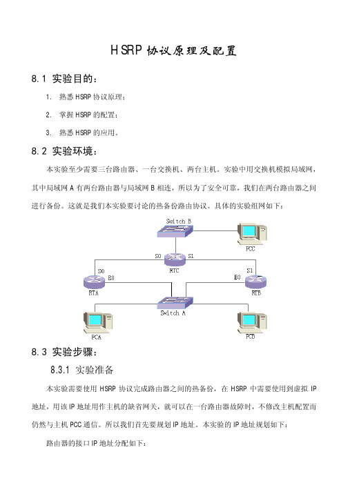
8.2 实验环境:本实验至少需要三台路由器、一台交换机、两台主机。
实验中用交换机模拟局域网,其中局域网A有两台路由器与局域网B相连,所以为了安全可靠,我们在两台路由器之间进行备份。
这就是我们本实验要讨论的热备份路由协议。
具体的实验组网如下:8.3 实验步骤:8.3.1 实验准备本实验需要使用HSRP协议完成路由器之间的热备份,在HSRP中需要使用到虚拟IP 地址,用该IP地址用作主机的缺省网关,就可以在一台路由器故障时,不修改主机配置而仍然与主机PCC通信。
所以我们首先要规划IP地址。
本实验的IP地址规划如下:路由器的接口IP地址分配如下:RTA RTB RTCE0 10.110.32.11/21 10.110.32.10/21 10.110.10.100/24S0 1.0.0.1/24 1.0.0.2S1 2.0.0.1/24 2.0.0.2各主机的IP地址分配如下:PCA PCB PCCIP 10.110.32.20 10.110.10.30 10.110.10.1Gateway 10.110.32.1 10.110.10.1 10.110.10.1008.3.2 单备份组配置本实验需要路由器RTA与RTB实现热备份,并且正常时以RTA为活动路由器,并且在RTA由故障状态恢复正常时能继续担当活动路由器。
根据实验要求和HSRP协议原理可以设定RTA的优先级较高(默认值为100),同时置抢占标志,即可满足要求。
具体实验配置步骤很简单,不再赘述,下面列出各路由器的配置信息供您参考:RTA(config-if-Ethernet0)#show running-configNow create configuration...Current configuration!version 1.5.6hostname RTA!interface Aux0async mode interactiveencapsulation ppp!interface Ethernet0speed autoduplex autono loopbackip address 10.110.32.11 255.255.248.0standby 1 ip 10.110.32.1 //创建备份组并设定虚拟IP地址standby 1 preempt //设定抢占标志standby 1 priority 120 //设定优先级ip rip version 2 mcast //设定RIP协议版本!interface Serial0encapsulation pppip address 1.0.0.1 255.255.255.0ip rip version 2 mcast!interface Serial1encapsulation ppp!exitrouter ripno auto-summary //取消自动聚合功能network all!endRTB(config-if-Serial1)#show running-configNow create configuration...Current configuration!version 1.5.6hostname RTB!interface Aux0async mode interactiveencapsulation ppp!interface Ethernet0speed autoduplex autono loopbackip address 10.110.32.10 255.255.248.0standby 1 ip 10.110.32.1standby 1 preemptip rip version 2 mcast!interface Serial0encapsulation ppp!interface Serial1encapsulation pppip address 2.0.0.1 255.255.255.0ip rip version 2 mcast!exitrouter ripno auto-summarynetwork all!endRTC(config-if-Serial1)#show running-config Now create configuration...Current configuration!version 1.5.6logging consolehostname RTC!interface Aux0async mode interactiveencapsulation ppp!interface Ethernet0speed autoduplex autono loopbackip address 10.110.10.100 255.255.255.0ip rip version 2 mcast!interface Serial0clock-select DTECLK1encapsulation pppip address 1.0.0.2 255.255.255.0ip rip version 2 mcast!interface Serial1clock-select DTECLK1encapsulation pppip address 2.0.0.2 255.255.255.0ip rip version 2 mcast!exitrouter ripno auto-summarynetwork all!end注意:在配置动态路由协议时,由于使用的是RIP协议,该协议默认版本version 1不支持可变长子网掩码,而实验中设定的IP地址又是A类地址。
HSRP基本实验及其测试
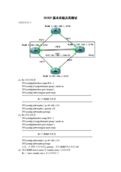
HSRP基本实验及其测试实验拓扑如下:(1)R1的基本配置SW1(config)#interface range f0/0 – 1SW1(config-if-range)#channel-group 1 mode onSW1(config)#interface port-channel 1SW1(config-if)#switchport mode trunk*****************************************************************R1中HSRP的配置****************************************************************** SW1(config-if)#standby 1 ip 192.168.1.254SW1(config-if)#standby 1 priority 120SW1(config-if)#standby preempt(2)R2的基本配置SW1(config)#interface range f0/0 – 1SW1(config-if-range)#channel-group 1 mode onSW1(config)#interface port-channel 1SW1(config-if)#switchport mode trunk*****************************************************************R2中HSRP的配置****************************************************************** SW2(config-if)#standby 1 ip 192.168.1.254SW2(config-if)#standby preempt注意,在SW2中没有指定priority,所以HSRP默认使用100(3)测试HSRP Active router和standby router之间的切换R1上show standby vlan 1显示结果如下:SW1#show standby vlan 1Vlan1 - Group 1State is Active2 state changes, last state change 00:07:18Virtual IP address is 192.168.1.254Active virtual MAC address is 0000.0c07.ac01Local virtual MAC address is 0000.0c07.ac01 (v1 default)Hello time 3 sec, hold time 10 secNext hello sent in 2.752 secsPreemption enabledActive router is localStandby router is 192.168.1.2, priority 100 (expires in 8.916 sec)Priority 120 (configured 120)IP redundancy name is "hsrp-Vl1-1" (default)SW2#show standby vlan 1Vlan1 - Group 1State is Standby1 state change, last state change 00:08:34Virtual IP address is 192.168.1.254Active virtual MAC address is 0000.0c07.ac01Local virtual MAC address is 0000.0c07.ac01 (v1 default)Hello time 3 sec, hold time 10 secNext hello sent in 1.396 secsPreemption enabledActive router is 192.168.1.1, priority 120 (expires in 9.372 sec)Standby router is localPriority 100 (default 100)IP redundancy name is "hsrp-Vl1-1" (default)******************************************************************************* 将SW1和SW3之间的链路中断,观察active router 和standby router的转换******************************************************************************* SW1(config)#interface vlan 1SW1(config-if)#shutdown*Mar 1 00:36:19.947: %HSRP-5-STATECHANGE: Vlan1 Grp 1 state Active -> Init Type escape sequence to abort.Sending 5, 100-byte ICMP Echos to 192.168.1.4, timeout is 2 seconds:!!!!!Success rate is 100 percent (5/5), round-trip min/avg/max = 24/58/84 ms这个结果说明,当avtive router SW1出现故障时,standby router SW2开始运行,而用户的服务不会中断;因为这个时候已经配置了抢占,所以SW2这个时候成了avtive router*Mar 1 00:36:19.747: %HSRP-5-STATECHANGE: Vlan1 Grp 1 state Standby -> Active@@@@@@@@@@@@@@@@@@@@@@@@@@@@@@@@@@@@@@@@@@ SW1(config)#interface vlan 1SW1(config-if)#no shutdown*Mar 1 00:40:14.063: %HSRP-5-STATECHANGE: Vlan1 Grp 1 state Listen -> Active可见,当SW1的故障恢复的时候,它又称为了avtive router,因为配置的时候配置了抢占。
HSRP实验指导书

HSRP实验实验6-1HSRP实验学习目标•了解网关冗余技术。
•配置HSRP实现对业务网关的冗余原理HSRP 是Cisco 的专有协议。
HSRP(Hot Standby Router Protocol)把多台路由器组成一个“热备份组”,形成一个虚拟路由器。
这个组内只有一个路由器是活动的(Active),并由它来转发数据包,如果活动路由器发生了故障,备份路由器将成为活动路由器。
从网络内的主机来看,网关并没有改变。
HSRP 路由器利用HELLO 包来互相监听各自的存在。
当路由器长时间没有接收到HELLO包,就认为活动路由器故障,备份路由器就会成为活动路由器。
HSRP 协议利用优先级决定哪个路由器成为活动路由器。
如果一个路由器的优先级比其它路由器的优先级高,则该路由器成为活动路由器。
路由器的缺省优先级是100。
一个组中,最多有一个活动路由器和一个备份路由器。
拓扑图图1拓扑操作步骤步骤一配置汇聚交换机HSRP1、将《VLAN间路由实验》中保存的拓扑打开,要求服务器区设备访问网络主走SW1,图书馆区设备访问网络主走SW2,交换机管理网段主走SW1。
步骤二配置服务器区域VLAN101 HSRP。
1、VLAN101 standby 10.X.0.13、在SW1上关闭F0/1接口验证HSRP切换过程4、在SW1上开启F0/1接口验证HSRP回切过程步骤三配置图书馆区域VLAN103 HSRP 1、VLAN103 standby 10.X.2.12、查看HSRP状态步骤四配置管理VLAN2 HSRP 1、VLAN2 standby 10.X.129.254步骤五设置二层交换机缺省网关及PC机IP参数1、设置SW3-SW6缺省网关(由于模拟器只支持HSRP配置,不支持具体功能,所以接入交换机网关配置为10.0.129.1,本应为standby IP)2、设置PC1 和PC3的IP地址等参数(由于模拟器只支持HSRP配置,不支持具体功能,所以PC1网关配置为10.0.0.251,所以PC3网关配置为10.0.2.252,本应为standby IP)步骤六保存配置1、全网设备保存配置,防止掉电配置丢失。
HSRP+PVST实验

SW-B
interface Vlan10 ip address 192.168.10.253 255.255.255.0 standby 10 ip 192.168.10.254 standby 10 priority 120 standby 10 preempt ! interface Vlan20 ip address 192.168.20.252 255.255.255.0 standby 20 ip 192.168.20.254 standby 20 priority 150 standby 20 preempt
实验分析
静态路由设计
来回路径一致 如何实现路由备份:利用Metric值
实验分析
静态路由设计
来回路径一致 如何实现路由备份:利用Metric值
实验配置
SW-A
interface Vlan10 ip address 192.168.10.252 255.255.255.0 standby 10 ip 192.168.10.254 standby 10 priority 150 standby 10 preempt ! interface Vlan20 ip address 192.168.20.253 255.255.255.0 standby 20 ip 192.168.20.254 standby 20 priority 120 standby 20 preempt
Interface Vl10 Vl20
SWSW-B#sh standby bri P | Grp Prio P 10 120 P 20 150 P indicates configured to preempt. State Standby Active Active Standby Virtual IP 192.168.10.252 local 192.168.10.254 192.168.20.253 192.16tandby bri P | Grp Prio P 10 150 P 20 120 P indicates configured to preempt. State Active Standby Active Standby Virtual IP local 192.168.10.253 192.168.10.254 192.168.20.252 local 192.168.20.254
hsrp实现网关备份

试验报告制作人:何贝贝实验目的:通过hsrp协议实现网关备份。
实现路由器之间的负载均衡。
•HSRP备份组的成员–活跃路由器负责转发发送到虚拟路由器的数据包,通过HELLO消息来通告其活跃的角色–备份路由器负责监视HSRP组的运行状态,主要监视活跃路由器,通过HELLO消息通告其他路由器其备份的角色–虚拟路由器是向终端用户代表一台可以连续工作的路由器–其他路由器转发经过它们的数据包,但是不转发虚拟路由器的数据包活跃路由器和备份路由器的选择:1.看优先级:优先级越大,谁做活跃路由器2.看接口ip地址:ip地址越大,谁做活跃路由器第一步:路由器配置ip地址Router1上的设置Router(config)#hostname R1R1(config-if)#ip add 192.168.13.1 255.255.255.0 R1(config-if)#no shutdownR1(config)#int s0/0R1(config-if)#ip add 192.168.12.1 255.255.255.0 Router 2和router3同理第二步:启用协议Router1上的设置R1(config)#router ripR1(config-router)#version 2R1(config-router)#network 192.168.12.0R1(config-router)#network 192.168.13.0R1(config-router)#passive-interface e1/0 Router2上的设置R2(config)#router ripR2(config-router)#version 2R2(config-router)#network 192.168.12.0R2(config-router)#network 192.168.20.0R2(config-router)#network 192.168.23.0 Router3上的设置R3(config)#router ripR3(config-router)#version 2R3(config-router)#network 192.168.13.0R3(config-router)#network 192.168.23.0R3(config-router)#passive-interface e1/1第三步:查看路由表Router1上的路由表R1#show ip routeCodes: C - connected, S - static, R - RIP, M - mobile, B - BGPD - EIGRP, EX - EIGRP external, O - OSPF, IA - OSPF inter areaN1 - OSPF NSSA external type 1, N2 - OSPF NSSA external type 2E1 - OSPF external type 1, E2 - OSPF external type 2i - IS-IS, su - IS-IS summary, L1 - IS-IS level-1, L2 - IS-IS level-2ia - IS-IS inter area, * - candidate default, U - per-user static routeo - ODR, P - periodic downloaded static routeGateway of last resort is not setC 192.168.12.0/24 is directly connected, Serial0/0C 192.168.13.0/24 is directly connected, Ethernet1/0R 192.168.20.0/24 [120/1] via 192.168.12.2, 00:00:02, Serial0/0R 192.168.23.0/24 [120/1] via 192.168.12.2, 00:00:02, Serial0/0 Router2上的路由表R2#show ip routeCodes: C - connected, S - static, R - RIP, M - mobile, B - BGPD - EIGRP, EX - EIGRP external, O - OSPF, IA - OSPF inter areaN1 - OSPF NSSA external type 1, N2 - OSPF NSSA external type 2E1 - OSPF external type 1, E2 - OSPF external type 2i - IS-IS, su - IS-IS summary, L1 - IS-IS level-1, L2 - IS-IS level-2ia - IS-IS inter area, * - candidate default, U - per-user static routeo - ODR, P - periodic downloaded static routeGateway of last resort is not setC 192.168.12.0/24 is directly connected, Serial0/0R 192.168.13.0/24 [120/1] via 192.168.23.1, 00:00:01, Serial0/1[120/1] via 192.168.12.1, 00:00:17, Serial0/0C 192.168.20.0/24 is directly connected, Ethernet1/0C 192.168.23.0/24 is directly connected, Serial0/1Router3上的路由表R3#show ip routeCodes: C - connected, S - static, R - RIP, M - mobile, B - BGPD - EIGRP, EX - EIGRP external, O - OSPF, IA - OSPF inter areaN1 - OSPF NSSA external type 1, N2 - OSPF NSSA external type 2E1 - OSPF external type 1, E2 - OSPF external type 2i - IS-IS, su - IS-IS summary, L1 - IS-IS level-1, L2 - IS-IS level-2ia - IS-IS inter area, * - candidate default, U - per-user static routeo - ODR, P - periodic downloaded static routeGateway of last resort is not setR 192.168.12.0/24 [120/1] via 192.168.23.2, 00:00:01, Serial0/1C 192.168.13.0/24 is directly connected, Ethernet1/1R 192.168.20.0/24 [120/1] via 192.168.23.2, 00:00:01, Serial0/1C 192.168.23.0/24 is directly connected, Serial0/1第四步:将router1和router3用hsrp协议配置成网关Router1上的设置R1(config)#int e1/0R1(config-if)#standby 1 ip 192.168.13.254R1(config-if)#standby 1 priority 120R1(config-if)#standby preemptR1(config-if)#standby 1 authentication md5 key-string cisco Router3上的设置R3(config)#int e1/1R3(config-if)#standby 1 ip 192.168.13.254R3(config-if)#standby 1 preemptR3(config-if)#standby 1 authentication md5 key-string cisco 没有设置优先级,默认为100客户机的设置Pc1上的设置Pc2上的设置验证:pc1 去和pc2通信正常通信查看router1上的standby配置R1#show standby briefP indicates configured to preempt.|Interface Grp Prio P State Active Standby Virtual IPEt1/0 1 120 Active local 192.168.13.2 192.168.13.254关闭router1上的e1/0接口看是否能正常通信R1(config)#int e1/0R1(config-if)#shutdow正常通信,查看router1和router3上的standby配置Router1上的配置R1#show standby briefP indicates configured to preempt.|Interface Grp Prio P State Active Standby Virtual IPEt1/0 1 120 Init unknown unknown 192.168.13.254Router3上的配置R3#show standby briefP indicates configured to preempt.|Interface Grp Prio P State Active Standby Virtual IPEt1/1 1 100 P Active local unknown 192.168.13.254第五步:配置端口跟踪当router1上的s0/0接口出故障时,router1将没有到达pc2所在网段的路由,然而,router1和router3直接的以太网没有问题。
HSRP实验详解及案例

热备份路由协议(HSRP)一、HSRP的相关概念HSRP(hot standby router protocol)是思科私有的一种协议,二、HSRP的配置1、配置为HSRP的成员switch(config-if)#standby group-number ip irtual-ip-addressgroup-number:默认组是0号,范围0~255irtual-ip-address:虚拟HSRP路由器的ip地址,即网段的网关地址。
例如:switch(config-if)#(no)standby 10 ip 192.168.1.2542、配置HSRP的优先级switch(config-if)#standby group-number priority priority-valuepriority-value:范围是0~255,默认值是100.例如:switch(config-if)#(no)standby 10 priority 2003、配置HSRP的占先权switch(config-if)#standby group-number preempt4、配置Hello消息的计时器switch(config-if)#standby group-number times hellotime holdtimehellotime:默认时间是3s,设置范围是1~255,holdtime:保持时间是hello时间的3倍,默认是10s。
例如:switch(config-if)#standby 10 times 2 85、配置HSRP的端口跟踪switch(config-if)#standby group-number track i nterface-type mod/num interface-priority interface-priority:当端口失效时,路由器的热备份优先级将降低的数值,默认为10.例如:switch(config-if)#standby 10 track fastEthernet 0/1 1006、查看HSRP状态switch#show standby [interface-type mod/num] [group-number] briefinterface-type mod/num:要显示的端口类型和序号。
企业网络高级技术-HSRP
R2(config)#inter f0/0
R2(config-if)#ip add 172.16.10.10 255.255.255.0
R2(config-if)#no shut
R2(config-if)exit
2.设置默认网关:地址为该HSRP组的虚拟IP地址,由自己设定;
R2(config)#ip default-gateway 172.16.10.254
3.关闭路由器的路由功能;
R2(config)#no ip routing
R3:
端口f0/0
1.配置IP地址;
R3(config)#inter f0/0
R3(config-if)#ip add 172.16.10.1 255.255.255.0
R3(config-if)#no sh
2.把路由器配置成一个HSRP组的成员,即加入一个HSRP组;
R3(config-if)#standby 172 ip 172.16.10.254
3.关闭端口重定向,防止主机发现HSRP组中路由器的真实MAC地址(活跃路由器地址)
R3(config-if)#no ip redirects
R3(config-if)#exit
端口f1/0
1.配置IP地址;
R3(config)#inter f1/0
R1(config-if)#no sh
R1(config-if)exit
2.设置默认网关:地址为该HSRP组的虚拟IP地址,由自己设定;
R1(config)#ip default-gateway10.10.10.254
3.关闭路由器的路由功能;
R1(config)#no ip routing
实验40、HSRP的配置
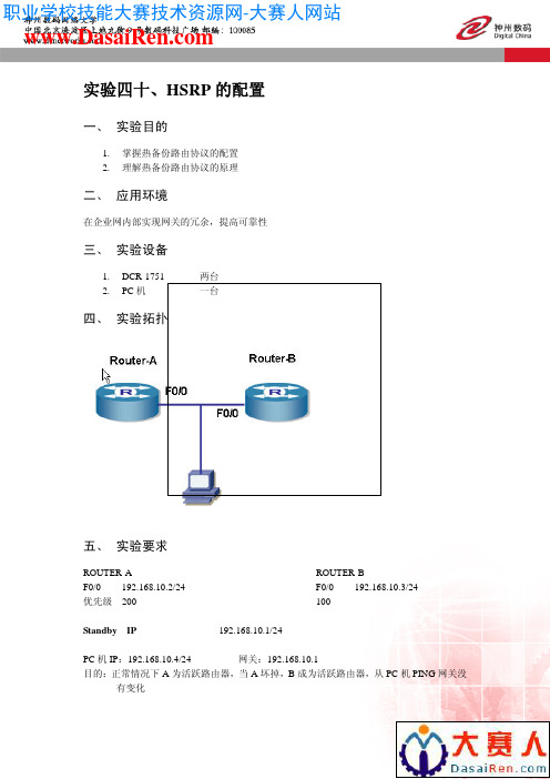
实验四十、HSRP的配置一、实验目的1.掌握热备份路由协议的配置2.理解热备份路由协议的原理二、应用环境在企业网内部实现网关的冗余,提高可靠性三、实验设备1.DCR-1751 两台2.PC机一台四、实验拓扑五、实验要求ROUTER-A ROUTER-B192.168.10.2/24 F0/0192.168.10.3/24F0/0优先级200 100Standby IP 192.168.10.1/24PC机IP:192.168.10.4/24 网关:192.168.10.1目的:正常情况下A为活跃路由器,当A坏掉,B成为活跃路由器,从PC机PING网关没有变化六、实验步骤第一步:配置接口地址,并测试连通性第二步:配置HSRP路由器A的配置:Router-A_config#int f0/0Router-A_config_f0/0#ip address 192.168.10.2 255.255.255.0 Router-A_config_f0/0#standby priority 200 !配置优先级Router-A_config_f0/0#standby ip 192.168.10.1 !配置虚拟地址Router-A_config_f0/0#stand authentication router !配置认证密码路由器B的配置Router-B_config#int f0/0Router-B_config_f0/0#ip address 192.168.10.3 255.255.255.0Router-B_config_f0/0#standby priority 100Router-B_config_f0/0#standby ip 192.168.10.1Router-B_config_f0/0#stand authentication routerRouter-B_config_f0/0#^Z第三步:配置PC机IP地址和网关,并测试网关第四步:验证Router-A#sh standbyFastEthernet0/0 - Group 0HSRP State is ActiveVirtual IP address : 192.168.10.1/24 (config)Virtual Mac address : 0000.0c07.ac00Active Router IP : 192.168.10.2Standby Router IP : 192.168.10.3Preempt is not setCurrent Priority is 200Config Priority is 200HSRP timer : hello 3 s(default) hold 10s (default) HSRP current timer : hello 2 active 0 standby 9 Authentication string is routerRouter-B#sh standbyFastEthernet0/0 - Group 0HSRP State is StandbyVirtual IP address : 192.168.10.1/24 (config)Virtual Mac address : 0000.0c07.ac00Active Router IP : 192.168.10.2Standby Router IP : 192.168.10.3Preempt is not setCurrent Priority is 100Config Priority is 100HSRP timer : hello 3 s(default) hold 10s (default) HSRP current timer : hello 3 active 9 standby 0 Authentication string is router第五步:关闭路由器A,从PC机PING 网关七、注意事项和排错1.Standby IP 要设置一致2.认证密码要相同3.PC机的网关是Standby IP,也就是虚拟地址八、配置序列Router-B#sh runBuilding configuration...Current configuration:!!version 1.3.2Eservice timestamps log dateservice timestamps debug dateno service password-encryption!hostname Router-B!ip host a 192.168.1.1ip host c 192.168.2.2!!interface FastEthernet0/0ip address 192.168.10.3 255.255.255.0no ip directed-broadcaststandby ip 192.168.10.1!interface Serial1/0ip address 192.168.1.2 255.255.255.0no ip directed-broadcast!interface Async0/0no ip addressno ip directed-broadcast!!九、共同思考1.HSRP的作用是什么?2.虚拟地址与真实地址有什么关系?3.有哪些定时器?十、课后练习请将地址改为10.0.0.0/24重复以上实验十一、相关命令详解standby priority, standby preempt为了配置HSRP为了恢复其缺省值,使用no格式命令。
实验四:HSRP
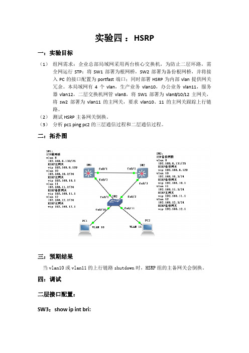
实验四:HSRP一:实验目标(1)组网需求:企业总部局域网采用两台核心交换机,为防止二层环路,需全网运行STP:将SW1部署为根网桥,SW2部署为备份根网桥,并将接入PC的接口配置为portfast端口;同时部署HSRP为内部vlan提供网关冗余。
本局域网有4个vlan,生产业务vlan10,办公业务vlan11,服务器vlan12,二层交换机网管vlan8,将SW1部署为vlan8/10/12主网关,将sw2部署为vlan11的主网关,要求vlan10、11的主网关跟踪上行链路。
(2)测试HSRP主备网关倒换。
(3)分析pc1 ping pc2的三层通信过程和二层通信过程。
二:拓扑图三:预期结果当vlan10或vlan11的上行链路shutdown时,HSRP组的主备网关会倒换。
四:调试二层接口配置:SW3:show ip int bri:三层接口配置: SW1:show ip int bri:SW2:show ip int bri:STP配置:SW1:SW2:SW3:HSRP配置:SW1中:VLAN8:VLAN 10:VLAN 11:VLAN 12:SW2中:Vlan8:Vlan10:Vlan11:Vlan12:Sw1中vlan10的上行链路跟踪:Sw2中vlan11的上行链路跟踪:五:测试SW1中Show ip int bri:SW2中Show ip int bri:未将sw1的上行链路showdown时:Sw1中:Show standby bri:Sw2中:Show standby bri:将sw1上行链路接口fa0/12 shutdown后:Sw1中:Show standby bri:Sw2中:Show standby bri:重新将SW1中的fa0/12口打开:Pc1 ping pc2:六:总结与原理分析PC1 ping PC2的数据流分析:PC1—SW3—SW1—SW3—PC2PC2—SW3—SW1—SW2—SW1—SW3—PC1①Pc1封装icmp包,发现未知目的MAC地址且目的IP与自己不在同一个网段,则封装一个ARP请求,请求的目的IP为网关IP,目的MAC为全F;②在通过fa0/10口时,arp请求被打上了vlan10 的标签;③进入sw3,sw3查询mac地址表,发现没有pc1 的mac地址,便更新mac表;④由于配置了生成树协议,相对于vlan10,sw3的fa0/2口是阻塞的,所以arp请求被交换机从fa0/1口发送到三层交换机sw1;⑤Sw1收到arp请求后,发现目的ip是自身的,然后拆vlan10标,更新mac地址表,便封装一个arp应答,封装时打上vlan10的标,从fa0/3口单播出去;⑥Sw3收到arp应答,查询mac地址表后,从fa0/10转发出去,在出口拆掉vlan10的标签;⑦Pc1收到arp应答,更新自身的arp缓存表,重新封装icmp包,其目的mac是网关,目的IP是pc2的IP地址,将封装好的icmp包,通过fa0/10口送往SW3;⑧Icmp包在fa0/10口被打上vlan10的标签;⑨Icmp包进入sw3,sw3查询mac地址表,把icmp包从fa0/1口转发出去;⑩SW1收到icmp包,拆vlan10标,发现目的IP地址不是自己的,但是网关却是已知的vlan11,且不知道目的mac地址,便封装一个arp请求,并打上vlan11的标签,洪泛出去;⑪由于配置了生成树协议,所以SW3的Fa0/2口相对于vlan11是阻塞的,所以ARP请求从fa0/3口发送到SW3;⑫SW3收到了arp请求后将其洪泛,arp请求从fa0/11口出去,在通过fa0/11口时被拆掉vlan11的标签;⑬Pc2收到arp请求,更新自己的arp缓存表后,封装一个arp应答;⑭Arp应答从fa0/11口进入SW3时被打vlan11的标签;⑮SW3收到arp应答后,更新mac地址表,然后从fa0/1口转发给SW1;⑯SW1收到arp应答后,拆除arp应答的vlan11的标签,更新mac地址表,重新封装icmp包,将ICMP转发给SW3;⑰SW3收到ICMP包后,将ICMP包转发给PC2,在通过sw3的fa0/11口时,icmp包的vlan11标签被拆除;⑱Pc2收到icmp包后,发现目的IP地址,mac地址均为自己的后,封装一个icmp回应包,通过SW3的fa0/11口时被打上vlan11的标签,之后进入SW3;⑲Icmp回应包进入SW3后被SW3通过fa0/1口转发到SW1;⑳由于配置了HSRP,且SW1是vlan11的备份路由,所以SW1需通过查路由表,将icmp回应包转发给SW2;21SW2收到icmp回应包后,拆掉vlan11的标签,更新mac地址表和路由表,发现icmp包的目的IP是自己网段内的IP地址,重新封装一个icmp回应包,并打上vlan10的标签,SW2的端口Fa0/3连接的SW3的Fa0/2相对于vlan10是阻塞的,所以打了vlan10标签的数据流将被发送到SW1;22SW1收到icmp回应包后,更新自己的mac地址表和路由表,并查询mac地址表后,将其转发到SW3;23SW3收到icmp回应包后,查询mac地址表,将其通过fa0/10口转发,icmp 包在通过fa0/10口时,被拆除vlan10的标签;24Pc1收到icmp回应包。
HSRP实验
HSRP实验实验目的:1.了解HSRP的工作原理,HSRP是如何提供网关的备份。
2.清楚HSRP路由器的几个状态,并且知道HSRP是如何选举活跃和备份路由器,HSRP的几个状态。
3.知道HSRP中优先级、占先权、端口跟踪的作用。
并且能够配置优先级、占先权、端口跟踪。
4.清楚HSRP中虚拟MAC的组成,计时器,消息类型,发送地址等等。
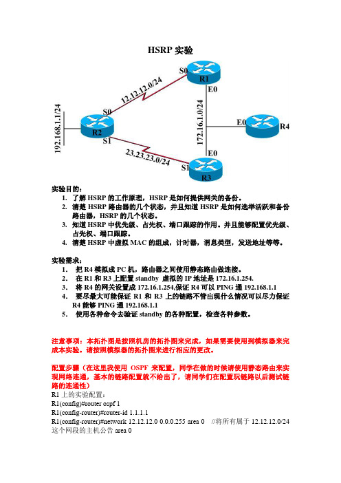
实验需求:1.把R4模拟成PC机,路由器之间使用静态路由做连接。
2.在R1和R3上配置standby 虚拟的IP地址是172.16.1.254.3.将R4的网关设置成172.16.1.254,保证R4可以PING通192.168.1.14.要尽最大可能保证R1和R3上的链路不管出现什么情况可以尽力保证R4能够PING通192.168.1.15.使用各种命令去验证standby的各种配置,检查各种参数。
注意事项:本拓扑图是按照机房的拓扑图来完成,如果需要使用到模拟器来完成本实验。
请按照模拟器的拓扑图来进行相应的更改。
配置步骤(在这里我使用OSPF来配置,同学在做的时候请使用静态路由来实现网络连通,基本的链路配置就不给出了,请同学们在配置玩链路以后测试链路的连通性)R1上的实验配置:R1(config)#router ospf 1R1(config-router)#router-id 1.1.1.1R1(config-router)#network 12.12.12.0 0.0.0.255 area 0 //将所有属于12.12.12.0/24这个网段的主机公告area 0R1(config-router)#network 172.16.1.0 0.0.0.255 area 0R1(config-router)#int e0R1(config-if)#standby 1 ip 172.16.1.254 //在E0口上配置HSRP,组编号是1虚拟IP地址是172.16.1.254R1(config-if)#R2上的实验配置R2(config)#router ospf 1R2(config-router)#router-id 2.2.2.2R2(config-router)#network 12.12.12.0 0.0.0.255 area 0R2(config-router)#network 23.23.23.0 0.0.0.255 area 0R2(config-router)#network 192.168.1.0 0.0.0.255 area 0R2(config-router)#R3上的实验配置R3(config)#router os 1R3(config-router)#router-id 3.3.3.3R3(config-router)#network 23.23.23.0 0.0.0.255 area 0R3(config-router)#network 172.16.1.0 0.0.0.255 area 0R3(config-router)#int e0R3(config-if)#standby 1 ip 172.16.1.254 //在E0口上配置HSRP,组编号是1虚拟IP地址是172.16.1.254R3(config-if)#需要主意:如果希望2个路由器共同维护一个HSRP组,那么要求保证2个路由器有相同的组编号和虚拟IP地址R4上的配置:(R4我们模拟成主机,如果希望把路由器模拟成主机需要关闭路由另外在给路由器配置网关)R4(config)#no ip routing //关闭路由功能R4(config)#ip default-gateway 172.16.1.254 //配置一个默认网关,需要主意网关和路由功能只能生效一个,希望网关生效就需要关闭路由功能。
实验37交换机HSRP实验

实验三十七、交换机HSRP实验一、 实验目的1、熟悉HSRP协议的使用方式和配置方法;2、理解HSRP协议的适用场合。
二、 应用环境大部分网络中的PC都是指定默认网关的,PC通过默认网关达到上网的目的。
如果作为默认网关的交换机损坏,所有使用该网关为下一跳主机的通信必然要中断。
即便配置了多个默认网关,如不重新启动终端设备,也不能切换到新的网关。
HSRP就是为了避免静态指定网关的缺陷而设计的。
在网络中有至少两台设备作为PC的网关存在,并且这两台设备可以虚拟出一个相同的IP作为PC的网关,也就是说一个IP地址可以对应两台交换机设备,任何一台交换机失效,都不会影响下面PC的通信。
HSRP,全称Hot Standby Routing Protocol,原理类似于服务器HA群集,两台或更多的三层设备以同样的方式配置成Cluster,创建出单个的虚拟路由器,然后客户端将网关指向该虚拟路由器。
最后由HSRP决定哪个设备扮演真正的默认网关。
三、 实验设备1、DCRS-7604(或6804)交换机1台2、DCRS-5526S交换机1台3、HUB或交换机1台4、PC机2-4台5、Console线1-2根6、直通网线若干根五、 实验要求1、在交换机7604和交换机5526S上分别划分基于端口的VLAN:交换机 VLAN 端口成员 IP1 24 10.1.157.1/24DCRS-7604100 1 192.168.100.2/2410 8-16 192.168.10.1/24DCRS-5526S1 24 10.1.157.2/24100 1 192.168.100.3/2420 8-16 192.168.20.1/242、PC1-PC4的网络设置为:设备 IP地址 gateway MaskPC1 192.168.100.101 192.168.100.1255.255.255.0PC2 192.168. 100.102 192.168.100.1255.255.255.0PC3 192.168.10.2 192.168.10.1 255.255.255.0PC4 192.168.20.2 192.168.20.1 255.255.255.03、验证:无论拔掉192.168.100.1的线还是192.168.100.2的线,PC1和PC2不需要做网络设置的改变都可以与PC3和PC4通信。
- 1、下载文档前请自行甄别文档内容的完整性,平台不提供额外的编辑、内容补充、找答案等附加服务。
- 2、"仅部分预览"的文档,不可在线预览部分如存在完整性等问题,可反馈申请退款(可完整预览的文档不适用该条件!)。
- 3、如文档侵犯您的权益,请联系客服反馈,我们会尽快为您处理(人工客服工作时间:9:00-18:30)。
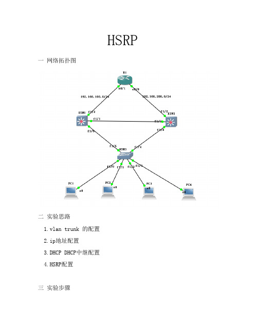
目录HSRP实验过程及报告 (2)实验环境: (2)实验拓扑: (2)实验目的: (2)实验过程: (3)1 配置交换机 (3)2 测试HSRP (5)3测试HSRP跟踪 (8)实验总结: (10)HSRP实验过程及报告实验环境:DynamipsGUI模拟器模拟出4台cisco3640三层交换机。
两台开启HSRP协议,设备之间使用Ethernetchannel绑定的两条线路互联。
其余两台交换机分别连接到这两台交换机。
实验拓扑:实验拓扑如图1实验目的:熟悉HSRP协议,验证HSRP网关冗余特性,测试HSRP抢占过程及HSRP接口跟踪。
实验过程:1 配置交换机在交换机SW1配置F0/0.F0/1接口加入channel-group 1 并将port-channel 1 配置为trunk模式。
SW1(config)#int range f0/0 - 1SW1(config-if-range)#channel-group 1 mode onCreating a port-channel interface Port-channel1SW1(config-if-range)#*Mar 1 01:23:58.639: %EC-5-BUNDLE: Interface Fa0/0 joined port-channel Po1 *Mar 1 01:23:58.935: %EC-5-BUNDLE: Interface Fa0/1 joined port-channel Po1 SW1(config-if-range)#*Mar 1 01:24:01.415: %LINEPROTO-5-UPDOWN: Line protocol on Interface Port-channel1, changed state to upSW1(config-if-range)#exitSW1(config)#int port-channel 1SW1(config-if)#switchport mode trunkSW1(config-if)#endSW1#sh etherchannel suFlags: D - down P - in port-channelI - stand-alone s - suspendedR - Layer3 S - Layer2U - in useGroup Port-channel Ports-----+------------+-----------------------------------------------------------1 Po1(SU) Fa0/0(P) Fa0/1(P)在交换机SW2上同样的配置。
.SW2(config)#int range f0/0 - 1SW2(config-if-range)#chanSW2(config-if-range)#channel-group 1 mode onCreating a port-channel interface Port-channel1SW2(config-if-range)#*Mar 1 01:24:38.119: %EC-5-BUNDLE: Interface Fa0/0 joined port-channel Po1 *Mar 1 01:24:38.391: %EC-5-BUNDLE: Interface Fa0/1 joined port-channel Po1 SW2(config-if-range)#int port*Mar 1 01:24:40.971: %LINEPROTO-5-UPDOWN: Line protocol on Interface Port-channel1, changed state to upSW2(config-if-range)#exitSW2(config)#int port-channel 1SW2(config-if)#switchport mode trunkSW2#shSW2#sh etherchannel summaryFlags: D - down P - in port-channelI - stand-alone s - suspendedR - Layer3 S - Layer2U - in useGroup Port-channel Ports-----+------------+-----------------------------------------------------------1 Po1(SU) Fa0/0(P) Fa0/1(P)配置HSRPSW1(config)#int vl 1SW1(config-if)#ip add 192.168.1.11 255.255.255.0SW1(config-if)#standby 10 ip 192.168.1.100SW1(config-if)#standby 10 priority 110SW1(config-if)#standby 10 preemptSW1(config-if)#*Mar 1 03:57:44.467: %HSRP-5-STA TECHANGE: Vlan1 Grp 10 state Speak -> Standby*Mar 1 03:57:44.967: %HSRP-5-STATECHANGE: Vlan1 Grp 10 state Standby -> Active查看HSRP状态Vlan1 - Group 10State is Active2 state changes, last state change 00:00:59Virtual IP address is 192.168.1.100Active virtual MAC address is 0000.0c07.ac0aLocal virtual MAC address is 0000.0c07.ac0a (v1 default)Hello time 3 sec, hold time 10 secNext hello sent in 0.936 secsPreemption enabledActive router is localStandby router is unknownPriority 110 (configured 110)IP redundancy name is "hsrp-Vl1-10" (default)先配置HSRP的为活跃状态,抢占模式,优先级为110(手动配置)。
SW2(config-if)#ip add 192.168.1.22 255.255.255.0SW2(config-if)#standby 10 ip 192.168.1.100SW2(config-if)#standby 10 preemptSW2(config-if)#*Mar 1 04:01:09.207: %HSRP-5-STA TECHANGE: Vlan1 Grp 10 state Speak -> Standby查看SW2的HSRP状态Vlan1 - Group 10State is Standby1 state change, last state change 00:00:50Virtual IP address is 192.168.1.100Active virtual MAC address is 0000.0c07.ac0aLocal virtual MAC address is 0000.0c07.ac0a (v1 default)Hello time 3 sec, hold time 10 secNext hello sent in 0.908 secsPreemption enabledActive router is 192.168.1.11, priority 110 (expires in 8.792 sec)Standby router is localPriority 100 (default 100)IP redundancy name is "hsrp-Vl1-10" (default)该设备为standby状态,配置了抢占模式,优先级为默认的100。
2 测试HSRP使用SW3尝试不停ping虚拟IP 192.168.1.100,期间切换主备交换机,产看切换情况。
SW1(config)#int vl 1SW1(config-if)#shutSW1(config-if)#*Mar 1 04:21:17.062: %HSRP-5-STA TECHANGE: Vlan1 Grp 10 state Active -> InitSW1(config-if)#*Mar 1 04:21:19.066: %LINK-5-CHANGED: Interface Vlan1, changed state to administratively down*Mar 1 04:21:20.066: %LINEPROTO-5-UPDOWN: Line protocol on Interface Vlan1, changed state to downSW1(config-if)#关闭了SW1上的VLAN 1,查看交换机SW2上的HSRP情况。
SW2#sh stan*Mar 1 04:21:06.262: %HSRP-5-STATECHANGE: Vlan1 Grp 10 state Standby -> ActiveSW2#sh stanVlan1 - Group 10State is Active8 state changes, last state change 00:00:07Virtual IP address is 192.168.1.100Active virtual MAC address is 0000.0c07.ac0aLocal virtual MAC address is 0000.0c07.ac0a (v1 default)Hello time 3 sec, hold time 10 secNext hello sent in 1.828 secsPreemption enabledActive router is localStandby router is unknownPriority 100 (default 100)IP redundancy name is "hsrp-Vl1-10" (default)可以看到SW2的HSRP状态为Active,观察交换机SW3的ping包情况SW3#ping 192.168.1.100 repeat 1000Type escape sequence to abort.Sending 1000, 100-byte ICMP Echos to 192.168.1.100, timeout is 2 seconds:!!!!!!!!!!!!!!!!!!!!!!!!!!!!!!!!!!!!!!!!!!!!!!!!!!!!!!!!!!!!!!!!!!!!!!!!!.!!!!!!!!!!!!!!!!!!!!!!!!!!!!!!!!!!!!!!!!!!!!!!!!!!!!!!!!!!!!!!!!!中间黄色部分为中断过程,是由于HSRP自动切换了活跃设备所引起的,由于切换了活跃交换机,所以导致有一个包是被丢弃的。