变速箱箱体的机械加工工艺规程
汽车变速箱箱体加工工艺及夹具设计

汽车变速箱箱体加工工艺及夹具设计
汽车变速箱箱体加工工艺:
1. 预处理:将箱体零件进行清洗、除油等处理。
2. 外观检查:进行外观检查,确认箱体零件是否存在缺陷或划痕等问题。
3. 装夹:将箱体零件放入夹具中进行装夹,确保零件不会因加工过程中移动和变形。
4. 粗加工:采用车削和铣削等工艺对箱体零件进行粗加工,以移除多余的金属材料,制作出初步形状。
5. 精加工:在粗加工完成后,进行精加工,采用平面磨或者线切割等工艺,对箱体零件进行加工,确保精度和表面质量。
6. 清洗:将加工完成的箱体零件进行清洗,清除可能存在的金属屑和油脂等。
7. 组装:将加工完成的箱体零件进行组装。
夹具设计:
1. 针对汽车变速箱箱体的形状和工艺特点,设计夹具,确保夹具能够牢固地固定零件,不会因为零件形状而导致变形和移动。
2. 考虑到加工和清洗的需要,夹具应该设计成易于拆卸和清洗的形式。
3. 使用夹具夹持箱体时,夹具表面应该保证平整和光滑,以避免对箱体表面造成损伤。
4. 对于一些需要双面加工的箱体零件,可以采用双面夹具进行
加工,以提高工作效率。
5. 在夹具的设计中应该考虑到工作人员的安全和作业的舒适性。
机械制造及自动化专业毕业论文--变速箱箱体制造工艺规程及专用夹具设计

摘要本次设计是变速箱箱体零件的加工工艺规程及其专用夹具设计。
变速箱箱体零件的主要加工表面是平面及孔系。
一般来说,保证平面的加工精度要比保证孔系的加工精度容易。
因此,本设计遵循先面后孔的原则。
并将孔与平面的加工明确划分成粗加工和精加工阶段以保证孔系加工精度。
基准选择以变速箱箱体的输入轴和输出轴的支承孔作为粗基准,以顶面与两个工艺孔作为精基准。
主要加工工序安排是先以支承孔系定位加工出顶平面,再以顶平面与支承孔系定位加工出工艺孔。
在后续工序中除个别工序外均用顶平面和工艺孔定位加工其他孔系与平面。
支承孔系的加工采用的是坐标法镗孔。
整个加工过程均选用组合机床。
夹具选用专用夹具,夹紧可靠,机构可以不必自锁。
因此生产效率较高。
适用于大批量、流水线上加工。
能够满足设计要求。
关键词变速箱;加工工艺;专用夹具AbstractThe design is about the special-purpose clamping apparatus of the machining technology process and some working procedures of the gearbox parts. The main machining surface of the gearbox parts is the plane and a series of hole. Generally speaking, to guarantee the working accuracy of the plan e is easier than to guarantee the hole’s. So the design follows the principle of plane first and hole second. And in order to guarantee the working accuracy of the series of hole, the machining of the hole and the plane is clearly divided into rough machining stage and finish machining stage. The supporting hole of the input bearing and output bearing is as the rough datum. And the top area and two technological holes are as the finish datum. The main process of machining technology is that first, the series of supporting hole fix and machine the top plane, and then the top plane and the series of supporting hole fix and machine technological hole. In the follow-up working procedure, all working procedures except several special ones fix and machine other series of hole and plane by using the top plane and technological hole. The machining way of the series of supporting hole is to bore hole by coordinate. The combination machine tool and special-purpose clamping apparatus are used in the whole machining process. The clamping way is to clamp by pneumatic and is very helpful. The instruction does not have to lock by itself. So the product efficiency is high. It is applicable for mass working and machining in assembly line. It can meet the design requirements.Key words gearbox machining technology special-purpose clamping apparatus目录1 序言 (1)2.零件加工工艺规程 (2)2.1概述 (2)2.2零件的作用 (2)2.3零件的工艺分析 (2)2.4确定工艺方案的原则及注意问题 (2)2.4.1粗、精加工分开原则 (3)2.4.2工序集中与分散的原则 (3)2.4.3制定工艺方案应注意的其它问题 (4)2.5 确定箱体的生产类型 (4)2.6工艺规程的设计 (5)2.6.1 确定毛坯材料及尺寸 (5)2.6.2 定位基准的选择 (5)2.6.3 制定工艺路线 (5)2.7 工序尺寸的基本要求 (6)2.7.1粗铣上盖接合面 (6)2.7.2在上盖接合面上钻铰定位孔 (6)2.7.3 铰两定位孔 (6)2.7.4粗铣前端面,粗铣后端面 (7)2.7.5铣两侧窗口面和凸台面(不含取力窗口面) (7)2.7.6铣取力窗口面 (7)2.7.7 铣倒档轴孔内端面 (7)2.7.8上盖接合面,前后端面三面钻孔 (7)2.7.9 左右侧面两面钻铰孔 (7)2.7.10锪沉头孔 (7)2.7.11粗镗前后端面轴承孔,扩倒档轴孔 (7)2.7.12上盖接合面及前后端面攻丝(三面攻) (8)2.7.13 两侧面攻丝 (8)2.7.14插槽 (8)2.7.15精镗前后端面轴承孔,铰倒档轴承孔 (8)2.7.16精铣前端面,精铣后端面 (8)2.7.17 去毛刺 (8)2.7.18 清洗 (8)2.7.19 检验 (8)2.8确定切削用量和基本工时 (8)2.8.1工序5 粗精铣上盖接合面 (8)2.8.2工序6 钻铰上盖接合面定位孔 (9)2.8.3工序7 粗铣前后端面 (10)2.8.4工序8 铣两侧窗口面和凸台面(不含取力窗口面) (11)2.8.5工序9 铣取力窗口面 (11)2.8.6工序10 铣倒档轴孔内端面 (12)2.8.7工序11 上盖接合面,前后端面三面钻孔 (12)2.8.8工序12左右两侧面钻孔 (14)2.8.9工序13粗镗前后端面轴承孔,扩倒档轴孔 (15)2.8.10工序14粗镗前后端面轴承孔,扩倒档轴孔 (16)2.8.11工序15上盖接合面及前后端面攻丝(三面攻) (17)2.8.12工序16两侧面攻丝 (19)2.8.13工序17精镗前后端面轴承孔,铰倒档轴孔 (21)2.8.14工序18精铣前后端面 (22)2.9切削用量的选择依据 (22)2.9.1铣削 (23)2.9.2钻孔 (23)2.9.3扩孔和铰孔 (23)2.9.4攻螺纹 (24)2.9.5机床精度及机床参数 (24)2.10 各种加工工艺和加工方法 (25)2.10.1平面加工工艺 (25)2.10.2螺纹加工工艺 (25)2.11常用工艺主要工序能达到的精度和表面粗糙度 (25)2.11.1平面加工 (25)2.11.2螺纹孔加工 (26)3 组合机床总体设计—“三图一卡” (27)3.1零件加工工序图 (27)3.1.1零件加工工序图的作用与内容 (27)3.1.2 绘制零件加工工序图的规定及注意事项 (27)3.2零件加工示意图 (27)3.2.1零件加工示意图的作用和内容 (28)3.2.2 绘制零件加工示意图的注意事项 (28)3.2.3 刀具的选择 (28)3.2.4 确定主轴类型、尺寸 (28)3.2.5标注联系尺寸 (28)3.2.6标注切削用量 (29)3.2.7 动力部件工作循环及行程的确定 (29)3.3 机床联系尺寸图 (29)3.3.1 机床联系尺寸图的作用与内容 (29)3.3.2 绘制机床联系尺寸图之前应确定的主要内容 (30)3.3.3 绘制机床联系尺寸图的注意事项 (31)3.4机床生产率计算卡 (31)4 夹具的设计 (34)4.1对铣床夹具体的要求 (34)4.2夹具体的毛坯结构 (34)4.3夹具元件的选择与设计 (34)4.4 专用夹具的设计步骤 (35)4.4.1研究原始资料 (35)4.5 绘制夹具总装配图 (35)4.6 标注夹具总装配图上各部分尺寸和技术要求 (36)4.7夹具公差配合的制订 (36)4.7.1 制订夹具公差与技术条件的依据 (36)4.7.2制定夹具公差和技术条件的基本原则 (36)4.8夹具公差的制订 (37)4.9夹具技术条件的制订 (37)4.9.1 定位元件之间或定位元件对夹具体底面之间的相互位置要求 (37)4.9.2定位元件与连接元件间的相互位置要求 (37)4.9.3 对刀元件与连接元件间的相互位置要求 (37)4.9.4 定位元件与引导元件间的相互位置要求 (37)4.10夹具设计部分的计算 (37)4.10.1基准的选择 (37)4.10.2切削夹紧力的计算 (38)4.10.3定位误差的分析 (38)结论 (40)致谢................................................................................................................. 错误!未定义书签。
汽车变速箱加工工艺流程

汽车变速箱加工工艺流程下载温馨提示:该文档是我店铺精心编制而成,希望大家下载以后,能够帮助大家解决实际的问题。
文档下载后可定制随意修改,请根据实际需要进行相应的调整和使用,谢谢!并且,本店铺为大家提供各种各样类型的实用资料,如教育随笔、日记赏析、句子摘抄、古诗大全、经典美文、话题作文、工作总结、词语解析、文案摘录、其他资料等等,如想了解不同资料格式和写法,敬请关注!Download tips: This document is carefully compiled by theeditor. I hope that after you download them,they can help yousolve practical problems. The document can be customized andmodified after downloading,please adjust and use it according toactual needs, thank you!In addition, our shop provides you with various types ofpractical materials,such as educational essays, diaryappreciation,sentence excerpts,ancient poems,classic articles,topic composition,work summary,word parsing,copy excerpts,other materials and so on,want to know different data formats andwriting methods,please pay attention!汽车变速箱加工工艺流程一、准备工作阶段在开始汽车变速箱的加工之前,有一系列的准备工作需要完成。
X6020B卧式升降台铣床变速箱机械加工工艺规程及部分工序的夹具设计与此工序的NC指令的编写

摘要本次设计的课题是X6020B 卧式升降台铣床变速箱机械加工工艺规程及精镗I 、II 、III 组支承孔的夹具。
变速箱体是X6020B 卧式升降台铣床传动系统最主要的部件之一,它将机床的主轴箱、进给箱等零件组成一个整体并使之保持正确的位置。
因此,变速箱的加工质量将直接影响机器的性能与使用寿命。
本设计旨在提高X6020B 卧式升降台铣床变速箱的加工效率,由此我们首先对变速箱体的结构和工艺进行了仔细的分析,然后确定了一套合理的加工方案对其进行加工。
加工方案要求简单,操作方便,并能保证零件的加工质量。
最后,依照确定好的方案,按照正确的加工工序将它加工出来,并使之满足零件的设计要求。
此外,为了提劳动生产率,降低劳动强度,保证加工质量,需设计专用夹具,为此选择了第10道工序——镗8100H φ,580⨯φ的夹具设计,以满足加工过程的需要。
关键词 变速箱体;工艺规程;夹具ABSTRACTThe title of the design is technics regulations for machining of the X6020B vertical lift platform mill machine and boring machine clamp design for three groups of hole.Transmission case is a key part in the drive system of the vertical lift platform mill machine, which unity headstock、feed change gearbox and other parts and maintain their right position. So its ormance and longevity of service. This paper aims at enhancing the machining efficiency of transmission case. we need to take analysis of the structure and technics of the transmission case, and then find out a reasonable precept, which should be simple, operate conveniently and make sure the machining quality. we carry machining according to the decided precept and right procedure to meet the design demand. for the sake of enhancing work productivity, reducing the work force and making certain the quality, we need to design special clamp. the tenth work procedure was choosed to be designed to meet the machining demand.Keywords transmission case;technics;regulations;clamp目录前言 (1)1 X6020B卧式升降台铣床的介绍 (2)1.1铣床的介绍 (2)1.2铣床的性能和用途 (3)1.3 X6020B卧式升降台铣床参数 (4)2 零件的分析 (5)2.1 零件的功用 (5)2.2 零件的工艺分析 (5)2.2.1 孔和平面的表面粗糙度要求 (5)2.2.2 平面的几何形状精度 (5)2.2.3轴孔精度 (5)2.3箱体的材料及毛坯种类的选择 (5)3 X6020B变速箱体的机械加工工艺规程设计 (6)3.1 变速箱体机械加工时的主要问题 (6)3.1.1 孔和平面的加工顺序 (6)3.1.2 粗,精加工分阶段进行 (6)3.1.3 孔系加工方案的选择 (6)3.2 机体机械加工时定位基准的选择 (7)3.2.1 .粗基准的选择 (7)3.2.2 精基准的选择: (7)3.3 制订工艺路线 (7)4 确定机械加工余量,工序尺寸及其公差 (17)4.1平面 (17)4.2 孔 (17)5 确定切削用量、工时定额、切削力及切削功率 (19)5.1 切削用量的选择原则 (19)5.1.1粗加工切削用量的选择原则 (19)5.1.2 切削深度的选择 (19)5.1.3 进给量的选择: (20)5.1.4 切削速度的选择: (20)5.1.5 精加工时切削用量的选择原则: (20)5.1.6 切削深度的选择: (20)5.1.7 进给量的选择: (20)5.1.8 切削速度的选择: (20)5.2 铣平面 (21)5.3 孔加工 (23)5.3.1 镗孔 (23)5.3.2 钻孔加工 (18)5.3.3 螺纹加工 (26)6 绘制零件-毛坯合图 (28)7 填写工艺过程卡和工序卡 (29)7.1 机械加工工艺过程的组成 (29)7.2 工序的合理组合 (29)8 夹具设计 (31)8.1 夹具的定义及分类 (31)8.2 机床夹具在机械加工中的作用 (31)8.3 机床夹具的组成 (26)8.3.1 定位装置 (26)8.3.2 夹紧装置 (26)8.3.3 对刀或导向装置 (26)8.3.4 连接元件 (26)8.3.5 夹具体 (27)8.3.6 其它装置或元件 (27)8.4 夹具方案 (27)8.4.1 对工件进行工艺分析 (27)8.4.2 定位装置的确定 (27)8.4.3 夹紧装置的确定 (28)8.4.4 计算夹紧力并确定螺杆直径 (29)8.4.5 镗模支架的结构和尺寸的确定 (30)8.4.6 镗模底座的结构尺寸的确定 (37)8.4.7 拟定本夹具的技术要求 (37)8.4.8 夹具的精度分析 (37)8.4.9镗套的选择 (32)9 某道工序的NC指令 (33)结束语 (394)主要参考文献 (35)致谢 (36)附录: (36)前言毕业设计是学生在校学习阶段的最后一个重要的教学环节,其目的是培养学生综合运用所学的专业和基础理论知识、独立解决本专业一般工程技术问题的能力,树立正确的设计思想的工作作风。
汽车变速箱上盖的机械加工工艺规程及夹具设计

摘要汽车变速箱上盖是汽车变速箱的重要组成部分。
它与变速箱箱体装配,为变速箱内部的齿轮、轴等工作元件提供一个稳定安全的工作环境,防止内部零件在暴露环境下工作。
上盖上还设计了检查窗,是为了便于观查内部元件的工作情况。
本设计说明书是在毕业设计过程中撰写完成的,是对变速箱上盖加工工艺、工装设计的说明、分析和论证。
主要内容有:上盖的工艺规程制定、典型加工工序分析、专用夹具设计、专用刀具设计、专用量具设计。
通过这些我对变速箱上盖零件制造活动有一个总体的,全貌的了解与把握,能够掌握金属切削过程的基本规律,掌握机械加工的基本知识,能选择加工方法与机床,刀具,夹具及加工参数,具备制定工艺规程的能力和掌握机械加工精度和表面质量的基础,初步具备分析解决现场工艺问题的能力。
关键词:工艺;工装;夹具;刀具ABSTRACTMotor vehicle gearbox shelters is an important component of the gearbox. Box it and gearbox assembly, the internal gear for the transmission, axle components, and other work.It provide a stable and secure working environment to prevent exposure of internal components in the working environment. Also stamped on the design of the inspection windows, in order to facilitate the investigation of the internal components of the work.The design specification is in the process of writing graduate design completed, the gearbox cover processing technology, tooling design of the note, analysis and feasibility studies. Elements include: the superstructure of developing a point of order, the typical processing of special fixture design, special-purpose tool designed for measuring tool design.I passed these on the gearbox cover parts manufacturing activities have an overall, the understanding and grasp the full picture, metal-cutting process to be able to master the basic law, grasp the basic knowledge of mechanical processing, and processing methods can choose machine tools, cutting tools, fixtures and processing Parameters, with the development of protocols and the ability to master precision machining and surface quality of the foundation, a preliminary analysis of the scene to solve problems.Key words: Technology; Tooling; Fixture; Tool目录绪论 (1)1 机械加工工艺规程的制定 (2)1.1零件的工艺性分析 (2)1.1.1 零件的功用 (2)1.1.2 零件的结构特点与工艺性 (2)1.1.3 主要加工表面及其技术要求 (2)1.2确定生产类型 (2)1.3零件毛坯选择 (4)1.3.1 零件毛坯材料选择 (4)1.3.2 变速箱上盖的毛坯 (4)1.3.3 毛坯的制造方式 (4)1.4零件加工工艺规程的制定 (5)1.4.1 选择加工方法和加工方案 (5)1.4.2 定位基准的选择 (5)1.4.3 热处理及检验的选择与安排 (6)1.4.4 拟定工艺路线 (6)1.4.5 选择各工序加工机床设备及工艺装备 (8)1.4.6 确定各工序的工序尺寸、表面粗糙度及检验方法 (10)1.4.7 确定典型工序的切削用量及工序基本工时定额 (11)1.4.8 工艺过程的技术经济性分析 (15)2 夹具设计 (16)2.1铣床夹具的设计 (16)2.1.1 夹具功能简图和工作原理 (16)2.1.2 铣床夹具的定位方案设计 (17)2.1.3 铣床夹具的定位误差分析 (18)2.1.4 切削力与夹紧力的计算 (18)2.1.5 铣床夹具的夹紧装置与机构设计 (21)2.1.6 铣床夹具的动力装置设计 (23)2.2钻床夹具的设计 (24)2.2.1 钻床夹具的定位方案设计 (24)2.2.2 钻床夹具的定位误差分析 (25)2.2.3 钻削力与夹紧力的计算 (26)2.2.4 夹具的夹紧装置与机构设计 (30)2.2.5 钻床夹具的动力装置设计 (32)3 专用刀、量具设计 (33)3.1专用刀具设计. (33)3.1.1 钻铰复合刀具设计应考虑的问题 (33)3.1.2 钻铰复合刀具设计步骤及方法 (34)3.1.3 钻铰复合刀具结构尺寸图 (36)3.2专用量具设计 (37)3.2.1 量规工作尺寸的确定 (37)3.2.2 量规的技术要求 (39)3.2.3 量规的结构尺寸 (39)结论 (41)致谢 (42)参考文献 (43)附录A 英文文献 (44)附录B 中文翻译 (52)绪论制造业是国家发展与社会进步的基础,而汽车制造将是未来面对普通消费者的主要的机械制造产品,而随着国家的发展人民生活水平的提高,人们对汽车的需求和要求必定变的更多,所以我们有必要对汽车及汽车零件的设计与加工投入更多的精力。
汽车变速箱壳体机械加工工艺规程及夹具设计
编号20171352113本科生毕业设计汽车变速箱壳体机械加工工艺规程及夹具设计Processing Technology and Fixture Design of Automobile Gearbox学生姓名专业机械电子工程学号指导教师分院机电工程分院2017年6月摘要本设计是汽车变速箱箱体零件的加工工艺规程及一些工序的专用夹具设计。
汽车变速箱箱体零件的主要加工表面是平面及孔系。
一般来说,保证平面的加工精度要比保证孔系的加工精度容易。
因此,本设计遵循先面后孔的原则。
并将孔与平面的加工明确划分成粗加工和精加工阶段以保证孔系加工精度。
基准选择以变速箱箱体的输入轴和输出轴的支承孔作为粗基准,以顶面与两个工艺孔作为精基准。
主要加工工序安排是先以支承孔系定位加工出顶平面,再以顶平面与支承孔系定位加工出工艺孔。
在后续工序中除个别工序外均用顶平面和工艺孔定位加工其他孔系与平面。
支承孔系的加工采用的是坐标法镗孔。
整个加工过程均选用组合机床。
夹具选用专用夹具,夹紧方式多选用气动夹紧,夹紧可靠,机构可以不必自锁。
因此生产效率较高。
适用于大批量、流水线上加工。
能够满足设计要求。
关键词:变速箱加工工艺专用夹具ABSTRACTThe design is about the special-purpose clamping apparatus of the machining technology process and some working procedures of the car gearbox parts. The main machining surface of the car gearbox parts is the plane and a series of hole. Generally speaking, to guarantee the working accuracy of the plane is easier than to guarantee the hole’s. So the design follows the principle of plane first and hole s econd. And in order to guarantee the working accuracy of the series of hole, the machining of the hole and the plane is clearly divided into rough machining stage and finish machining stage. The supporting hole of the input bearing and output bearing is as the rough datum. And the top area and two technological holes are as the finish datum. The main process of machining technology is that first, the series of supporting hole fix and machine the top plane, and then the top plane and the series of supporting hole fix and machine technological hole. In the follow-up working procedure, all working procedures except several special ones fix and machine other series of hole and plane by using the top plane and technological hole. The machining way of the series of supporting hole is to bore hole by coordinate. The combination machine tool and special-purpose clamping apparatus are used in the whole machining process. The clamping way is to clamp by pneumatic and is very helpful. The instruction does not have to lock by itself. So the product efficiency is high. It is applicable for mass working and machining in assembly line. It can meet the design requirements.Keywords: Gearbox machining-technology special-purpose clamping apparatus目录绪论 (1)第一章汽车变速箱加工工艺规程设计 (2)1.1 零件的分析 (2)1.1.1零件的作用 (2)1.1.2零件的工艺分析 (2)1.2 箱体加工的主要问题和工艺过程设计所应采取的相应措施 (2)1.2.1孔和平面的加工顺序 (3)1.2.2孔系加工方案选择 (3)1.3 变速箱箱体加工定位基准的选择 (5)1.3.1粗基准的选择 (5)1.3.2精基准的选择 (5)1.4变速箱箱体加工主要工序安排 (6)1.5机械加工余量、工序尺寸及毛坯尺寸的确定 (7)第二章专用夹具设计 (12)2.1加工工艺孔夹具设计 (12)2.1.1定位基准的选择 (12)2.1.2切削力的计算与夹紧力分析 (12)2.1.3夹紧元件及动力装置确定 (13)2.1.4钻套、衬套、钻模板及夹具体设计 (14)2.1.5夹具精度分析 (15)2.1.6夹具设计及操作的简要说明 (16)2.2粗铣前后端面夹具设计 (17)2.2.1定位基准的选择 (17)2.2.2定位元件的设计 (17)2.2.3定位误差分析 (18)2.2.4铣削力与夹紧力计算 (19)2.2.5定向键与对刀装置设计 (20)2.2.6夹紧装置及夹具体设计 (21)2.2.7夹具设计及操作的简要说明 (23)结论 (25)参考文献 (26)致谢 (27)绪论夹具设计作为高等工科院校教学的基本训练科目,在毕业设计中占极其重要的位置。
汽车变速箱上盖的机械加工工艺规程及夹具设计

摘要汽车变速箱上盖是汽车变速箱的重要组成部分。
它与变速箱箱体装配,为变速箱内部的齿轮、轴等工作元件提供一个稳定安全的工作环境,防止内部零件在暴露环境下工作。
上盖上还设计了检查窗,是为了便于观查内部元件的工作情况。
本设计说明书是在毕业设计过程中撰写完成的,是对变速箱上盖加工工艺、工装设计的说明、分析和论证。
主要内容有:上盖的工艺规程制定、典型加工工序分析、专用夹具设计、专用刀具设计、专用量具设计。
通过这些我对变速箱上盖零件制造活动有一个总体的,全貌的了解与把握,能够掌握金属切削过程的基本规律,掌握机械加工的基本知识,能选择加工方法与机床,刀具,夹具及加工参数,具备制定工艺规程的能力和掌握机械加工精度和表面质量的基础,初步具备分析解决现场工艺问题的能力。
关键词:工艺;工装;夹具;刀具ABSTRACTMotor vehicle gearbox shelters is an important component of the gearbox. Box it and gearbox assembly, the internal gear for the transmission, axle components, and other work.It provide a stable and secure working environment to prevent exposure of internal components in the working environment. Also stamped on the design of the inspection windows, in order to facilitate the investigation of the internal components of the work.The design specification is in the process of writing graduate design completed, the gearbox cover processing technology, tooling design of the note, analysis and feasibility studies. Elements include: the superstructure of developing a point of order, the typical processing of special fixture design, special-purpose tool designed for measuring tool design.I passed these on the gearbox cover parts manufacturing activities have an overall, the understanding and grasp the full picture, metal-cutting process to be able to master the basic law, grasp the basic knowledge of mechanical processing, and processing methods can choose machine tools, cutting tools, fixtures and processing Parameters, with the development of protocols and the ability to master precision machining and surface quality of the foundation, a preliminary analysis of the scene to solve problems.Key words: Technology; Tooling; Fixture; Tool目录绪论 (1)1 机械加工工艺规程的制定 (2)1.1零件的工艺性分析 (2)1.1.1 零件的功用 (2)1.1.2 零件的结构特点与工艺性 (2)1.1.3 主要加工表面及其技术要求 (2)1.2确定生产类型 (2)1.3零件毛坯选择 (4)1.3.1 零件毛坯材料选择 (4)1.3.2 变速箱上盖的毛坯 (4)1.3.3 毛坯的制造方式 (4)1.4零件加工工艺规程的制定 (5)1.4.1 选择加工方法和加工方案 (5)1.4.2 定位基准的选择 (5)1.4.3 热处理及检验的选择与安排 (6)1.4.4 拟定工艺路线 (6)1.4.5 选择各工序加工机床设备及工艺装备 (8)1.4.6 确定各工序的工序尺寸、表面粗糙度及检验方法 (10)1.4.7 确定典型工序的切削用量及工序基本工时定额 (11)1.4.8 工艺过程的技术经济性分析 (15)2 夹具设计 (16)2.1铣床夹具的设计 (16)2.1.1 夹具功能简图和工作原理 (16)2.1.2 铣床夹具的定位方案设计 (17)2.1.3 铣床夹具的定位误差分析 (18)2.1.4 切削力与夹紧力的计算 (18)2.1.5 铣床夹具的夹紧装置与机构设计 (21)2.1.6 铣床夹具的动力装置设计 (23)2.2钻床夹具的设计 (24)2.2.1 钻床夹具的定位方案设计 (24)2.2.2 钻床夹具的定位误差分析 (25)2.2.3 钻削力与夹紧力的计算 (26)2.2.4 夹具的夹紧装置与机构设计 (30)2.2.5 钻床夹具的动力装置设计 (32)3 专用刀、量具设计 (33)3.1专用刀具设计. (33)3.1.1 钻铰复合刀具设计应考虑的问题 (33)3.1.2 钻铰复合刀具设计步骤及方法 (34)3.1.3 钻铰复合刀具结构尺寸图 (36)3.2专用量具设计 (37)3.2.1 量规工作尺寸的确定 (37)3.2.2 量规的技术要求 (39)3.2.3 量规的结构尺寸 (39)结论 (41)致谢 (42)参考文献 (43)附录A 英文文献 (44)附录B 中文翻译 (52)绪论制造业是国家发展与社会进步的基础,而汽车制造将是未来面对普通消费者的主要的机械制造产品,而随着国家的发展人民生活水平的提高,人们对汽车的需求和要求必定变的更多,所以我们有必要对汽车及汽车零件的设计与加工投入更多的精力。
22汽车变速箱箱体加工工艺及粗精铣顶面夹具设计

汽车变速箱箱体加工工艺及粗精铣顶面夹具设计第一章汽车变速箱加工工艺规程设计1.1 零件的分析1.1.1 零件的作用变速箱箱体的主要作用是支承各传动轴,保证各轴之间的中心距及平行度,并保证变速箱部件与发动机正确安装。
因此汽车变速箱箱体零件的加工质量,不但直接影响汽车变速箱的装配精度和运动精度,而且还会影响汽车的工作精度、使用性能和寿命。
汽车变速箱主要是实现汽车的变速,改变汽车的运动速度。
汽车变速箱箱体零件的顶面用以安装变速箱盖,前后端面支承孔φ120 mm 、 80 mm 用以安装传动轴,实现其变速功能。
φ 1.1.2 零件的工艺分析由汽车变速箱箱体零件图可知。
汽车变速箱箱体是一个簿壁壳体零件,它的外表面上有五个平面需要进行加工。
支承孔系在前后端面上。
此外各表面上还需加工一系列螺纹孔。
因此可将其分为三组加工表面。
它们相互间有一定的位置要求。
现分析如下:(1)、以顶面为主要加工表面的加工面。
这一组加工表面包括:顶面的铣削加工;8 × M 10-6H 的螺孔加工;2 × φ12+0.027 mm 的工艺孔加工。
其中顶面有表面粗糙度要求为Ra 6.3um ,8 个螺孔均有位置度要求为φ0.3mm ,2 个工艺孔也有位置度要求为φ 0.1mm 。
(2)、以φ120 +0.03 mm 、φ 80 +0.013 mm 、φ100 +0.035 mm 的支承孔为主要加工表面的加工面。
这一组加工表面包括:2 个φ120 +0.03 mm 、2 个φ 80 +0.013 mm 和 1 个φ100 +0.035 mm 的孔;尺寸为365 ± 0.025mm 的与 2 × φ120 +0.03 mm 、 2 × φ 80+0.013 mm 的 4 个孔轴线相垂直的前后端面;前后端面上的 3 个 M 14-6 H 、个 M 10-6 H 的螺孔,16 以及 4 个φ15mm 、个φ 8mm 2 的孔;还有另外两个在同一中心线上与两端面相垂直的φ 30 +0..020 mm 的倒车齿轮轴孔及其内端面和两个 M10-6 H 的螺孔。
汽车变速箱壳体加工工艺
汽车变速箱壳体加工工艺
汽车变速箱壳体加工工艺:
1、机械加工:
(1)毛磨机加工:采用钻头和毛磨加工技术,通过钻头凸起加工变速
箱壳体表面,然后用毛磨机对壳体表面进行磨平。
(2)铣床加工:利用铣削技术,通过刀具在变速箱壳体上进行划痕加工,使零件表面形成狭窄带形痕,提高变速箱壳体表面粗糙度。
(3)钻井加工:利用钻井加工技术,在变速箱壳体上增加孔位,以满
足加工要求。
2、非机械加工:
(1)气压抛光:利用压缩空气的动能,通过抛光剂洗去变速箱壳体上
的锈蚀和污渍,使壳体成型和表面更加光滑,完成表面处理。
(2)电镀:采用电镀技术,将变速箱壳体表面处理成铝合金、锌、铬、钨和镍等不同的金属电镀,改善壳体强度,增强腐蚀抗性。
(3)喷射烤漆:采用喷射烤漆技术,在变速箱壳体表面喷洒油漆,使
壳体表面具有装饰性,增强外壳的防护性能。
3、质量检查:
(1)检查尺寸:通过接口、精密仪和滑卡检测变速箱壳体尺寸是否符
合标准要求,并验收零件质量;
(2)检查表面粗糙度:用毛料测试变速箱壳体表面粗糙度,确定粗糙度是否符合标准要求;
(3)检查材质:通过金相显微镜、纽扣试验和磁粉检查等技术,检查变速箱壳体材料是否合格。
变速箱箱体加工过程
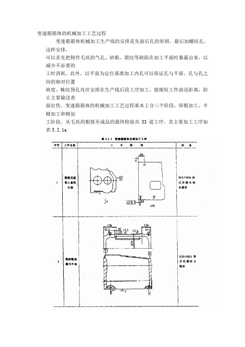
变速箱箱体的机械加工工艺过程变速箱箱体机械加工生产线的安排是先面后孔的原则,最后加螺纹孔。
这样安排,可以首先把铸件毛坯的气孔、砂眼、裂纹等缺陷在加工平面时暴露出来,以减少不必要的工时消耗。
此外,以平面为定位基准加工内孔可以保证孔与平面、孔与孔之间的相对位置袂度。
蛛纹预孔攻丝安排在生产线后段工序加工,能缩短工件油送距离,防止主要输送表面拉伤。
变速箱箱体的机械加工工艺过程基本上分三个阶段,即粗加工、半精加工和精加工阶段。
从毛坯的粗铣至成品的最终检验共33道工序。
其主要加工工序如表3.2.1a五、变速箱箱体加工工艺过程分析及典型夹具1.定位基准的选择。
变速箱箱体粗基准的选择有两种方式。
其一,为了保证主要轴承孔的加工余量均匀,箱体内零件间有足够的装配间隙,以轴承孔作为粗基准。
此方式夹具结构复杂,零件定位后需加辅助支承,工件稳定性较差。
CA1flC变速箱箱体就是以轴承孔作为粗基准的。
其二,是在变速箱箱体的毛坯上铸出作为粗基准的工艺凸台,为此要求工艺凸台至主要工作表面的毛坯面保持严格的尺寸和公差,LF06S带同步器变速箱箱体的粗基准就选用此方式,如图3.2.3所示。
这种粗基准选择可保证主要加工平面及轴承孔有足够的加工余量.并使加工余量均匀,工件定位稳定。
精基准选择是上盖联接平面和两个工艺孔。
此方案可使夹具结构简单、装夹工件方便可靠.适于自动线大t流水生产。
可以满足螺纹联接孔的技术要求。
但设计基准和工艺基准不重合,箱体前、后端面对轴承孔垂直度的精度不易保证。
CALOC 变速箱箱体的两个工艺孔安排在箱体的对角线上,对角线的长短影响定位精度。
LFi)55带同步器变速箱箱体的两个工艺孔安排在箱体的同一侧上,这既可满足定位精度,又可使夹具结构简单、调整容易。
如图3.2.4所示。
工艺基准为两个"12*g918,中心距为〔3fi7 t}.US)二的孔,而装配用的基准定位环孔为两个$13级罗mm孔,二者不能互代,因生产线较长,经多次装夹,定位精度下降或丧失。
汽车变速箱箱体加工工艺及夹具设计
摘要本设计是汽车变速箱箱体零件的加工工艺规程及一些工序的专用夹具设计。
汽车变速箱箱体零件的主要加工表面是平面及孔系。
一般来说,保证平面的加工精度要比保证孔系的加工精度容易。
因此,本设计遵循先面后孔的原则。
并将孔与平面的加工明确划分成粗加工和精加工阶段以保证孔系加工精度。
基准选择以变速箱箱体的输入轴和输出轴的支承孔作为粗基准,以顶面与两个工艺孔作为精基准。
主要加工工序安排是先以支承孔系定位加工出顶平面,再以顶平面与支承孔系定位加工出工艺孔。
在后续工序中除个别工序外均用顶平面和工艺孔定位加工其他孔系与平面。
支承孔系的加工采用的是坐标法镗孔。
整个加工过程均选用组合机床。
夹具选用专用夹具,夹紧方式多选用气动夹紧,夹紧可靠,机构可以不必自锁。
因此生产效率较高。
适用于大批量、流水线上加工。
能够满足设计要求。
关键词:变速箱;加工工艺;专用夹具AbstractThe design is about the special-purpose clamping apparatus of the machining technology process and some working procedures of the car gearbox parts. The main machining surface of the car gearbox parts is the plane and a series of hole. Generally speaking, to guarantee the working accuracy of the plane is easier than to guarantee the hole’s. So the design follows th e principle of plane first and hole second. And in order to guarantee the working accuracy of the series of hole, the machining of the hole and the plane is clearly divided into rough machining stage and finish machining stage. The supporting hole of the input bearing and output bearing is as the rough datum. And the top area and two technological holes are as the finish datum. The main process of machining technology is that first, the series of supporting hole fix and machine the top plane, and then the top plane and the series of supporting hole fix and machine technological hole. In the follow-up working procedure, all working procedures except several special ones fix and machine other series of hole and plane by using the top plane and technological hole. The machining way of the series of supporting hole is to bore hole by coordinate. The combination machine tool and special-purpose clamping apparatus are used inthe whole machining process. The clamping way is to clamp by pneumatic and is very helpful. The instruction does not have to lock by itself. So the product efficiency is high. It is applicable for mass working and machining in assembly line. It can meet the design requirements.Key words: Gearbox; machining technology; special-purpose clamping apparatus目录摘要.................................................... Abstract........................................................... 第1章汽车变速箱加工工艺规程设计............ 错误!未定义书签。
汽车变速箱箱体加工工艺及夹具设计

第一章汽车变速箱加工工艺规程设计1.1零件的分析1.1.1零件的作用题目给出的零件是汽车变速箱箱体。
变速箱箱体的主要作用是支承各传动轴,保证各轴之间的中心距及平行度,并保证变速箱部件与发动机正确安装。
因此汽车变速箱箱体零件的加工质量,不但直接影响汽车变速箱的装配精度和运动精度,而且还会影响汽车的工作精度、使用性能和寿命。
汽车变速箱主要是实现汽车的变速,改变汽车的运动速度。
汽车变速箱箱体零件的顶面用以安装变速箱盖,前后端面支承孔120mm、80mm用以安装传动轴,实现其变速功能。
1.1.2零件的工艺分析由汽车变速箱箱体零件图可知。
汽车变速箱箱体是一个簿壁壳体零件,它的外表面上有五个平面需要进行加工。
支承孔系在前后端面上。
此外各表面上还需加工一系列螺纹孔。
因此可将其分为三组加工表面。
它们相互间有一定的位置要求。
现分析如下:(1)、以顶面为主要加工表面的加工面。
这一组加工表面包括:顶面的铣削加工;8 M10-6H的螺孔加工;2 12°'027mm的工艺孔加工。
其中顶面有表面粗糙度要求为Ra6.3l m,8个螺孔均有位置度要求为0.3mm,2个工艺孔也有位置度要求为0.1mm。
(2)、以©120%03mm、©80七013mm、0100^035mm的支承孔为主要加工表面的加工面。
这一组加工表面包括:2个120 0.03mm、2个80 0.013mm和1个100 0.035mm 的孔;尺寸为365 _ 0.025mm 的与2 120 °03mm、2 80 0.013mm 的4个孔轴线相垂直的前后端面;前后端面上的3个M14-6H、16个M10-6H的螺孔,以及4个15mm、2个8mm的孔;还有另外两个在同一中心线上与两端面相垂直的30 Z5mm 的倒车齿轮轴孔及其内端面和两个M10-6H的螺孔。
其中前后端面有表面粗糙度要求为Ra6.3»m,3个M14-6H、16个M10-6H的螺孔,4个15mm > 2个8mm的孔均有位置度要求为0.3mm,两倒车齿轮轴孔内端面有尺寸要求为90o046mm及表面粗糙度要求为Ra3.2」m。
- 1、下载文档前请自行甄别文档内容的完整性,平台不提供额外的编辑、内容补充、找答案等附加服务。
- 2、"仅部分预览"的文档,不可在线预览部分如存在完整性等问题,可反馈申请退款(可完整预览的文档不适用该条件!)。
- 3、如文档侵犯您的权益,请联系客服反馈,我们会尽快为您处理(人工客服工作时间:9:00-18:30)。
毕 业 设 计 (论 文) 专 业 机械设计制造及其自动化 班 级 学生姓名 学 号 课 题 变速箱箱体的机械加工工艺规程分析 指导教师 李 云
2013 年 6月 11 日 1
摘 要 本设计是某叉车变速箱箱体零件的加工工艺规程及变速箱检修及常见故障诊断。某叉车变速箱箱体零件的主要加工表面是平面及孔系。一般来说,保证平面的加工精度要比保证孔系的加工精度容易。因此,本设计遵循先面后孔的原则。并将孔与平面的加工明确划分成粗加工和精加工阶段以保证孔系加工精度。粗基准选择顶面和两个输出轴孔为粗基准,以底面与两个定位销作为精基准。主要加工工序安排是先以支承孔系定位加工出顶平面,再以顶平面与支承孔系定位加工出工艺孔。在后续工序中除个别工序外均用顶平面和工艺孔定位加工其他孔系与平面。整个加工过程均选用组合机床。因此生产效率较高。适用于大批量、流水线上加工,能够满足设计要求。 叉车在使用的过程中,随着行驶里程的增多和作业时间的增加,变速器工作时不停地换挡,使变速器内的齿轮和操纵机构在使用中容易振动磨损,导致机构产生发响、跳档、乱档、渗漏等故障现象,严重时影响叉车的正常使用。常见故障有:变速器跳档、变速器乱档、变速器异响、变速器漏油等。因此变速箱需要定期检修维护以及掌握对变速箱的常见故障诊断是很有必要的。
关键词:变速箱;箱体;加工工艺;故障 2
Abstract The design is about the special purpose clamping apparatus of the machining technology process and some working procedures of the car gearbox parts. The main machining surface of the car gearbox parts is the plane and a series of hole. Generally speaking, to guarantee the working accuracy of the plane is easier than to guarantee the hole’s. So the design follows the principle of plane first and hole second. And in order to guarantee the working accuracy of the series of hole, the machining of the hole and the plane is clearly divided into rough machining stage and finish machining stage. The supporting hole of the input bearing and output bearing is as the rough datum. And the top area and two technological holes are as the finish datum. The main process of machining technology is that first, the series of supporting hole fix and machine the top plane, and then the top plane and the series of supporting hole fix and machine technological hole. In the follow up working procedure, all working procedures except several special ones fix and machine other series of hole and plane by using the top plane and technological hole. The machining way of the series of supporting hole is to bore hole by coordinate. The combination machine tool and special purpose clamping apparatus are used in the whole machining process. The clamping way is to clamp by pneumatic and is very helpful. The instruction does not have to lock by itself. So the product efficiency is high. It is applicable for mass working and machining in assembly line. It can meet the design requirements. Forklift trucks in use process, along with the increase in mileage and homework time increased, the transmission constantly shift at work, make the gears inside the transmission and control mechanism in the use of easy to wear and tear, vibration lead to produce hair ring, jumping gears, gears, such as seepage failure phenomenon, serious influence the normal use of forklift truck. Common faults are: the transmission gears, transmission gears, transmission of sound, transmission oil, etc. Therefore gearbox need regular maintenance, and to grasp the common fault diagnosis of gearbox is very be necessary.
Key words: Gearbox; machining technology; special purpose
clamping;faults 安徽建筑大学毕业设计(论文)
3 目 录
摘 要 .................................................................. 1 Abstract ................................................................. 2 第一章 绪 论 ........................................................... 5 1.1 概论 .............................................................. 5 1.2 国内外发展现状 ................................................... 5 1.3 课题的研究意义 ................................................... 5 第二章 箱体的三维建模 .................................................... 7 2.1 零件的分析 ....................................................... 7 2.1.1 零件的作用 ................................................. 7 2.1.2 零件的工艺分析 ............................................. 8 2.2 孔和平面的加工顺序 ............................................... 8 2.3 变速箱箱体加工定位基准的选择 ..................................... 9 2.3.1 粗基准的选择 ............................................... 9 2.3.2 精基准的选择 ............................................... 9 2.4 变速箱箱体加工主要工序安排 ....................................... 9 2.5 变速箱箱体零件的三维模拟 ........................................ 12 2.5.1 模拟软件UG NX6.0简介 ..................................... 12 2.5.2 箱体的模拟意义分析 ........................................ 12 2.5.3箱体的三维模拟步骤 .......................................... 12 第三章 加工余量确定及工序尺寸计算 ....................................... 15 3.1 毛坯余量 ......................................................... 15 3.1.1公差等级的确定 .............................................. 15 3.1.2 确定机械加工余量 .......................................... 15