德国通快编程手册
数控车床编程与操作教学课件三德国SIEMENS-802SC系统数控车床基础编程

课程章节名称
第二部分第一章基础编程
教学目的、要求
●能够准确掌握数控车床的坐标系并用于计算加工轮廓的坐标进行编程。
●能掌握德国SIEMENS-802S/C系统数控车床的编程指令含义、格式与使用注意事项,能运用SIEMENS-802S/C系统编程指令对零件进行编程加工。
重点
难点
SIEMENS系统刀具补偿指令的格式为:刀具号T+补偿号D。
3、SIEMENS系统刀具补偿的几点说明:
(1)建立补偿和撤销补偿程序段不能是圆弧指令程序段,一定要用G00或G01指令进行建立或撤销。
(2)如刀具号T后面没有补偿号D,则D1号补偿自动有效。如果编程时写D0则刀具补偿值无效。
五、螺纹编程指令及应用
(4)用圆弧终点坐标和圆弧张角进行圆弧插补,其程序段格式为:
G02/G03 X~Z~AR=~F~
(5)G05程序段格式为为:G05 X~Z~IX=~KZ=~F~
如果不知道圆弧的圆心、半径或张角,但已知圆弧轮廓上三个点的坐标,则可以使用G05指令。
2、SIEMENS-802S/C系统的的倒角、倒圆编程
倒角指令CHF=:
如N10 G01 X~Z~CHF=2
表示直线轮廓之间切入一直线并倒去棱角,程序中X、Y为两直线轮廓的交点Z的坐标。
倒圆角指令RND=:
表示直线轮廓之间、圆弧轮廓之间以及直线轮廓和圆弧轮廓之间切入一圆弧,圆弧与轮廓进行切线过渡,如:
N10 G01 X~Z~RND=~
三、循环编程指令
1、切槽循环LCYC93指令
二、圆弧、倒角、倒圆编程指令
1、圆弧插补指令G02/G03和G05
(1)用圆心坐标和圆弧终点坐标进行圆弧插补,其程序段格式与FANUC相同。
德国通快冲床安全操作规程
德国通快冲床安全操作规程1. 引言为了确保德国通快冲床的正常运行和操作人员的安全,制定本安全操作规程。
本规程适用于使用德国通快冲床的作业人员,旨在指导操作人员应遵守的安全操作步骤。
2. 操作前准备在使用德国通快冲床之前,操作人员应进行以下准备工作:•确保操作人员已经接受过相关的安全培训,并具备相关技能和知识。
•查看德国通快冲床的工作说明书,并了解其工作原理和操作要点。
•确保德国通快冲床的电源和电气线路处于良好状态,没有出现线路短路、漏电等安全隐患。
•检查冲床机体是否处于稳定状态,各部件是否固定牢固。
•确保工作区域周围没有杂物和障碍物,准备好必要的个人防护装备,如安全帽、护目镜、耳塞等。
3. 操作步骤在操作德国通快冲床时,操作人员应按照以下步骤进行操作:3.1 启动前检查在启动德国通快冲床前,操作人员应进行以下检查:1.检查电源和电气线路是否正常,没有异常现象。
2.检查冲床的工作台和上模具是否干净、平整,没有异物。
3.检查冲床机体是否处于稳定状态,各部件是否固定牢固。
4.检查冲床的润滑系统是否正常工作,润滑油是否充足。
3.2 启动冲床启动冲床前,操作人员应按以下步骤进行操作:1.确保没有人员站在冲床的活动范围内。
2.打开冲床的电源开关,并确认冲床的电气系统正常运行。
3.在启动按钮上按下按钮,启动冲床。
4.观察冲床的工作情况是否正常,如有异常情况,请立即停机并联系维修人员。
3.3 加工操作在进行加工操作时,操作人员应遵守以下要求:1.加工前,确保工作区域内没有其他杂物和工具。
2.将待加工的材料安全放置到冲床的工作台上,注意对齐和固定。
3.在操作过程中,保持双手的安全距离,避免手部与冲床机械部件接触。
4.遵循冲床的加工规范和操作要求,不得超负荷操作。
5.加工过程中,保持警惕,及时观察冲床的工作情况,如发现异常情况,请立即停机并联系维修人员。
3.4 停机与清洁在停机与清洁过程中,操作人员应按以下步骤进行操作:1.在加工完成后,关闭冲床的电源开关。
BROTHER编程说明

Br ot he r Ta pp in g C en te
1 / 83 ページ
N C 语
言
讲
义
NC言語 テキスト Brother
改订 2007.02
2 / 83 ページ
NC言語 テキスト Brother
1. 编程 之前
1.1『加 工前的 步骤』
【 解说 】 一般的步 骤为:通 过下面所 写的顺序 (1-7) 完成加工 程 在序这。 些步 骤中,主 要围绕“ 2.*NC程 序编制” 做了解释 说明。
130.000 0.000 0.000 0.000
3.2.2 扩 充工件坐 标系的选 择(G5 4.1)
指令形 式 :
G54.1Pn;
n:1~48
扩充工件
坐标
轴
1
2
~
X
-100.000 -120.000
Y
-200.000 -230.000
Z
130.000 100.000
A
0.000
0.000
B
0.000
数据库→ 1.工件坐 标原点
"记忆运作 模式"+单 一+空运行 +改写
3 / 83 ページ
8. 连续运作
程序编制也 会有失败品 产 在生 连。 续运作 之前,一定 要先确保程 序的确认修 正已完成。
NC言語 テキスト Brother
"记忆运作 模式"
4 / 83 ページ
NC言語 テキスト Brother
工作台移动 桌面横切机器 S2C 22B S2A 20A 等
3.2 『 工件坐 标系』
工件坐标原点
通快数控冲床编程手册
量单位。 ● 数据类型(名称):所描绘的特征是数字(Z)
还是文字(T)。二者均可允许。
3. 特征数据块的数目:规定特征数据块的数目, 它们分配给单个特征说明程序块的数值或文 字。 例 ZA, DA,1
3.3 块的选择性压制
定义
不必在每次程序运行时执行的程序块可以除去。 应除去的程序块在块号前加以标扦 “ / ”(斜杠)。 几个程序块可以连续除去。除去的程序块中的指令 就不执行,程序继续走到下一(未除去的)程序块。
完整文件/NC 编程
17
例 N110
G01
/N120
/N130
N140
X0 Y0 X20 Y35 X35 Y40 X60 Y30
,,”,T
MM,AT,1 120, 1,1,,‘ Memory requirement’
,,”,Z
MM,AT,1 130, 1,1,,‘ Material-ID’
,,”,T
MM,AT,1 140, 1,1,,‘ Sheet weight’
,,’kg’,Z
MM,AT,1 150, 1,1,,‘ Machining time’
SET_METRIC: 用公制编程 SET_INCH: 用英制编程
注意:计量单位标识与表头中表中参数的单位无 关。表中参数是由单独的特征说明块来描述的。
表头的作用是资料传递。它传递以下资料:
● 设置方案资料 ● 工具技术表 ● 板材搬运表 ● 工具主数据 ● 调用工具的指令
控制系统从表头抽出有关资料,把它们以表和界面的形 式显示在用户界面上。 当 NC 程序中的循环执行时,控制系统提取表和界面中 存储的数据,把它们用于其后执行的循环中。
Trumpf通快编程手册1
,,”,Z
MM,AT,1 30, 1,1,,‘Control Systems’
,,”,T
MM,AT,1 40, 1,1,,‘ Versions’
,,”,Z
MM,AT,1 50, 1,1,,‘ Firm’
,,”,T
MM,AT,1
60, 1,1,,‘Program number(without P!)’
若对特征文件要加一注释,应在其前冠以 “C”。
完整文件的语法
控制系统能评估的全部特征说明程序块列出于下:
BD
C
SET_METRIC:
C
BEGIN_SET_UP SCHEDULE_INFO
C
ZA,MM,18
MM,AT,1 10, 1,1,,‘ Machine’
,,”,T
MM,AT,1 20, 1,1,,‘ Type’
,,’min’,Z
MM,AT,1 160, 1,1,,‘ Comment’
,,”,T
MM,AT,1 170, 1,1,,‘ Flag automated’
,,’Bool’,Z
MM,AT,1 180, 1,1,,‘ Flag ToPsxxx-Program’
,,’Bool’,Z
C
ZA,DA,1
DA,‘TC2000’,1,’Bo Type3’,1,’Trumpf’,’1997,’USER’,
12
例:从完整文件中节录:
拆散后,它变为: L 10000099.SPF
完整文件/NC 编程
13
3 NC 码
在完整文件内, 和特征文件一样,NC 码(实际的加工 程序)由数据块组成,后者在表程序块“PROGRAM”中 以特征说明程序块的形式来说明。 NC 码包括: ● 子例程 ● 主程序 这些程序中的每一个都与一数据块相对应,每个数据 块是 NC 码的一部分。一主程序或子例程可分成: ● 程序开始 ● 程序处理 ● 程序结束
通快1000数控冲床简易操作流程知识分享

通快1000数控冲床简易操作流程
数控冲床1000 操作简略教程
机器正常启动的状态下,界面如下!当你想进行某一程序时请点击程序选择程序选择灵活进入
点击程序选择后进入选择列表!点取你要进行的程序,点击下一步
后提示你换刀具!换刀具时请注意刀具的位置、类型、尺寸、刀具长度以及刀具设置时候的板材公差!
机器的操作界面的认识
任何键的操作条件必须用脚踏踩掉光栅提示!
如光栅在亮的情况下,还可操作其他键。
属极度危险的状况
应紧急向上反应你所遇到的情况。
紧急停止键一般在停机维修时在用到,一般情况下不建议按紧急停止!
液压启动
参考位
光栅提示
暂停键
继续键
复位键<也称结束键>
开始程序
紧急停止
速度键
我们编程好的程序如何拷进机器呢?首先将程序拷进U盘。
将U盘插入机器右侧连接口!然后在机器界面中依次点击右侧的生产然后点击准备程序,然后再点击准备程序下边的黄色箭头选择驱动器。
然后再点击右侧的黄色箭头选择I盘也就是我们的U盘。
然后再U盘里找到你要输入进去的程序,然后点击左侧下边的准备程序。
当机器运行的时候突然停止,我们该怎样处理呢?点击灵活进入,然后选择下一步!
找到中断时候的那把刀具,<按下一步进行寻找>。
然后点击完成!完成之后再按机器操作界面的开始程序键!机器便可从中断点进行加工!。
通快 T3000 激光器说明书-en

By complying with this information • your avoid risks, • reduce the repair costs and down times
and • improve the reliability and service life of the laser marking sys-
Tab. 0-1
Manual for laser marking systems
This manual describes the following laser marking systems: • TruMicro® 3120 • TruMicro® 3220
Several properties as well as the handling and operation of the laser marking systems are similar. Headings, tables and other in-
Title of the document MA TruMicro® 3000 series
S7-300 S7-400语句表(STL)编程手册1-50
vi
前言 网上服务和技术支持
除了纸文件资料以外,我们在网上还提供有在线资料: /automation/service&support (英文网站) /service (中文网站) 在网上你可以找到: • 新闻列表可以向你提供不断更新的最新产品信息。 • 通过网上服务和技术支持部分的搜索功能,可以找到所需文件。 • 在论坛部分,全世界的用户和专家都可交流其经验。 • 通过我们在网上的代表处数据库,你可以找到当地的自动化与驱动集团代表
为了很好理解本手册,需要具有自动化技术的一般知识。
除此之外,还需要具备计算机知识以及操作系统MS Windows 2000 Professional 或 MS Windows XP Professional 下类似于 PC 的其它工作设备知识。
本手册的应用范围 本手册适用于 STEP 7 编程软件包的 5.3 版。
欧洲/非洲(纽伦堡)
美国(约翰森城)
授权
技术支持和授权
当地时间:星期一到星期五 当地时间:星期一到星期五
08:00:00 - 17:00 电话:+49 (0) 180 5050-222
08:00:00 - 17:00 电话:+1 (0) 770 740 3505
传真:+49 (0) 180 5050-223
v
前言
A&D 技术支持 遍布全球,24小时服务:
约翰逊市
纽伦堡
北京
总部(纽伦堡)
技术支持
通快激光编程
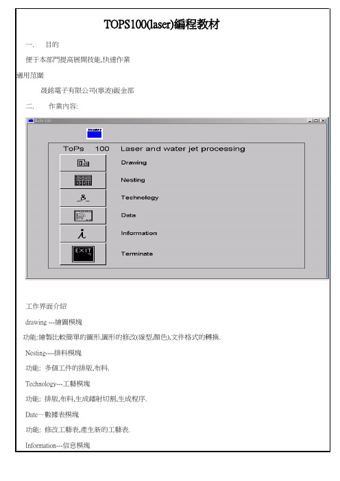
TOPS100(laser)編程教材一.目的便于本部門提高展開技能,快速作業適用范圍晟銘電子有限公司(寧波)鈑金部二.作業內容:工作界面介紹drawing ---繪圖模塊功能:繪製比較簡單的圖形,圖形的修改(線型,顏色),文件格式的轉換.Nesting----排料模塊功能: 多個工件的排版,布料.Technology---工藝模塊功能: 排版,布料,生成鐳射切割,生成程序.Date—數據表模塊功能: 修改工藝表,產生新的工藝表.Information---信息模塊功能:顯示版本信息.Terminate---退出開關功能: 退出界面一.drawing 繪圖模塊(一)Create(1)Line(線)2points: 兩點畫線Parallel: 偏移畫平行線,先選一條直線,再輸入要偏移的距離. Horizontal: 畫水平行線Vertical: 畫豎直線Tan point: 兩切點畫線.(二) Create 2(1)Notches-作工藝孔Dist Dist: 倒直角.(輸入兩個距離)Vertex : 對直角向內切一個正方形開口,或作切口並作工藝圓孔.必須選頂點.Acute angle: 切v型切口(輸入v型切口的深度,和夾角)Rectangular: 在直線的任一點上作矩形切口.(輸入深度和寬度,會依所點的點處為中心作切口) (2)Bevel –作倒斜角.Dist Dist : 倒斜角(輸入兩個距離值)Vertex: 作等距離的倒斜角(輸入一個距離值,然后確定頂點)(3)Rounding-倒圓角Radius: 倒圓角(輸入R角數值,再選擇一頂點,必須是交點)(4)Equidistant-等距離偏移.Generate: 對整個輪廓進行offset 偏移.(三) Modify-編輯(1)Move-移動2 points: 兩點移動.(任意確定兩點,來移動)Horizontal: 水平移動Vertical: 堅直移動(2)Rotate-旋轉2 points: 兩點移動旋轉.(確定起始點,確定目的點,輸入旋轉角度) Center : 中心旋轉.(3)Scale—縮放2 points: 兩點移動縮放(確定起始點,確定目的點,輸入縮放比例) Center: 中心縮放(4)Mirror-鏡像2 points: 兩點鏡像.(兩點確定直線,依此直線為中心軸來鏡像)Center: 中心鏡像(確定一點,然后依此點為中心旋轉180度)Horizontal: 水平鏡像Vertical: 堅直鏡像(5)Stretch-拉伸2 points: 兩點拉伸.Horizontal: 水平拉伸.Vertical: 堅直拉伸點擊命令,輸入距離.從右上角向左下角拉矩形框,來選擇元素.四)Modify 2- 編輯2(1)Rounding-圓角Modify-修改倒圓角大小(2)Elements-元素Split- 分割(先選要分割的元素,再選兩點)Merge—元素合并Split inters.pt-兩個相交元素的分割.(先選擇兩個要分割的元素,然后選擇要分割那一條線,相當於CAD中的trim 命令)Smash struct.-打散結構(3) Color- 改變顏色Selection-選擇.(選擇幾個輪廓元素來改變顏色)All—選擇全部(4) Type- 改變線型Selection-選擇(選擇幾個輪廓元素來改變線型)All-- 選擇全部(五)Macros-巨集Single hole-單孔.(先改變數據,可以選是圓,還是橢圓)Row of holes- 水平排孔(輸入起點,輸入終點.輸入要排列的數量) Circle of holes-以圓心為中心進行圓形阵列(六) Text-文字Create-- 建立文字.(設定好字高,字型,寬度)Modify-編輯現有的文字.(七) Drawing tools-繪圖工具Construction line –結構線Construction circle-結構圓Measuring- 測量上面這些命令和creat模塊中的功能相類同.它只是起到辅助繪圖的功能在鐳射切割時不會切割.可以刪除,也可以不用刪除.注:Drawing 模塊主要起繪圖和轉換文件格式的作用.首先把*.dxf文件調入界面.打開斷點檢視開關,一項一項檢查:a.看是否有斷點存在.b.是否有虛線或其它的非實線型存在.c.是否有其它的顏色線型.(鐳射機識別:白色的線是切割線.黃色的線是割印線.淡藍色的點是刺穿點)d.檢查是否有兩條直線之間的間距小于0.3的.(鐳射機小於0.3不會切割的.因為激光束的直徑是0.15)e.是否有重合線,重合點.檢查完畢無誤后.把它另存為*.geo 格式的文件.(編程時鐳射機僅識別這種格式的文件)就此第一步工作已經完成.完成了圖形文件的轉換,為進一步排料編程作好了準備.三.Nesting 排料模塊這一模塊的主要功能是實現單個工件或多個工件的排版.a.依次選擇new sheet然后彈出菜單設定板材的大小,厚度.b.用drawing tools 中的parallel工具繪出基準線.因為左下角不能距邊太近,否則鐳射在切割時,激光頭會撞在定位點上.通常設為15mmc.選擇load load additional part調入要排版的工件.在工件調入之后.先放在板材框之外.對於比較特殊的形狀可以通過旋轉工件來合理安排,盡可能的利用板材.(一)Modify--編輯(1)Move part –移動工件.2 points : 兩點移動All will: 動態移動Horizontal: 水平移動Vertical: 堅直移動(2)Number of parts-工件數量Section (-x +x): x軸方向數量的增加或減少.Number pcs(-y +y):y軸方向數量的增加或減少(3)Part distance-工件的距離(-x +x) : x軸方向的距離增加或減少(-y +y): y軸方向的距離增加或減少Parameters:調整距離增加或減少的增減量.Rotate (- +): 工件的旋轉.(4)Reference point-基準點(5)CSC distance –CSC距離注:a.在information 選項中可以查看單個工件的名字.b.點擊下拉箭頭.可以選擇copy 還是movec.在這種模式下可以排版多個工件.多用於量產的排程.排程時要考慮工件數量比例.d.排料結束后,把材料框外面的的工件刪除掉.e.在設定板材大小時要考慮,不要超出機器的最大加工范圍.(trumpf3030為3000*1500mm)f.排料完成檢查無誤后.存盤為*.taf文件.四. technology-工藝編程模塊在一模塊中主要是設定切割工藝,模擬,生成程序.點下拉菜單fileLoad&process…裝載進程.Load…裝載(常用此項,來調入文件,排料)(1) Create –建立(1.1) Current process rule –當前的工藝規則Set –用來設定,改變工藝規則(一個工藝表,通常會有多種的切割規則, 可以根據不同的情況.不用不同的切割規則.不過,通常會用到一種切割工藝,例如.sus 1.0板的切割,會有51401,51402,51404等規則我們通常選51401)processing- 排程Create—建立Enable- 啟動Delete—刪除Inhibit---- 禁止點擊下拉箭頭有幾個選項Contour—輪廓功能是在這種模式下,可以用delete來取消一個單件中輪廓的切割,綠色的切割線會變為白色的,用create 建立工藝,inhibit是禁止對它們進行建立和刪除的修改.enable是取消禁止.Single part- 單個工件可以用inhibit 來禁止整個工件切割.enable用來恢復切割part+ copies –一種類型的工件.可以禁止一種類型的工件切割.Until part—至到當前的工件從左邊第一個開始.至到當前這一個工件,是否禁止.Sheet –整張板,控制整張板上所有工件,是否切割(1.2) Collisions—碰點Check—檢查Listing—清單此功能主要檢查刺穿點,入切引線.等是否正常.(1.3) show-顯示主要顯示切割狀態.和一些文本信息.(2) Modify-編輯(2.1)Piercing-刺穿Properties. 改變刺穿的方式有兩種方式可以選擇regular-正常方式reduced-節約方式.(2.2)Approach-入切路徑Form –拖動方式(左鍵點入切引線,動態拖動來改變它的長度.)Displace-位置( 在輪廓上點一點,來改變它的入切點位置)這個功能比較常用.通常入切點盡量放在直角,拐角的地方.不要放在要定位的邊上.否則折床折邊時定位不準.同時也影響外觀.(2.3)Contour-輪廓Appr.+ withdr.—改變輪廓的切割属性.點擊命令后,會要求你選擇要改變的輪廓,點取一個輪廓后,會彈出一個對話框.里面有几項可供改變contour size –改變輪廓的切割方式,是大輪廓,還是小輪廓,如果是小輪廓,則刺穿點是粉紅色的.大輪廓則是紅色.Approach- 改變切割引線的length(長度)Radius(入切半徑)angle(角度)MicroJoint 工件微聯.Length來改變微聯的長度.通常是0.3不能太長,也不能太短,太長會有很大的毛點,太短會聯不住,其不到微聯的作用.(2.4)Corner treatment –圓角的修改.Create- 建立圓角Delete- 刪除圓角這個功能主要是對輪廓的所用尖角倒圓角.半徑可以改變.(3)Layout-排料Move part- 移動工件(移動工件是,其上的工藝也會移動的,但在nct沖床編程中移動,有時會只移動工件本身,而不移動布刀)Horizontally –水平移動Vertically - 豎直移動Two points - 兩點移動Rotate part- 旋轉工件(可以旋轉一個角度,來調整工件的排放位置)Two points –兩點旋轉Center—中心旋轉(4) Extras-增加(4.1) Circle correction-圓的補差此功能是對圓孔進行補差,在以前的鐳射機中會存在切割出的圓孔都會直徑偏小0.15,這主要是激光束走內線和外線的問題.激光束直徑為015mm.因此可通過這個功能來對其進行補差.點擊creat 命令后會彈出一個對話框在Correction of diameter中的Correction Value處輸入補差的值.15是切出來的和實際的一樣大.通常是0.16由於有切割點存在.對於鉚釘孔,可以加大一點.在Approach/withdrawal 中可以調節入切引線的尺寸,這和以前講過的一樣,不再重复Apply to 中包含三個選項Contour—輪廓Part+ copies-對所有的單一工件.(1)Positioning sequence- 位置順序Manual- 手動(手動一個一個點選來強制順序) Automatic- 自動Beginning- 開始(設定為第一個切割)End- 終止(設定為最后一個切割)(2)Rearrange –重新排序Before-前一個.(先點一個參考元素,再點一個要設定的元素最后點的那個就會在第一個點的元素前面切割.) After 后一個使用方法和before 一樣.Define begin-設定開始(功能和上面的beginning一樣) Define end -設定結束(功能和上面的end 一樣)點上面的下拉箭頭可以選擇是對工件強制,還是對輪廓強制(3) Tool-工具這個功能是選擇切割工藝表,不同的板材規格,板材厚度需要選用不同的工藝表(例如1.4301-10 是不锈鋼1.0 ,st37-10 是碳鋼1.0, AlMy3-10鋁合金1.0,1.0以下含1.0厚度的板全都用10工藝表, 1.6以下含1.6厚度的板全都用15工藝表)點擊Material ID 右邊的下拉箭頭,從中選擇合適的工藝表,然后點右邊的find鍵,所選工藝自動會在上面顯示出來,然后再點擊顯示出的工藝,會彈出一個對話框,用來選擇切割規則.當工藝選擇好後,還要點選processing下拉菜單,並點start 生成一次,否則不會改變工藝.(4) NC program- 生成程序在上面所有動作,設定全部完成以后.模擬檢查沒問題后就可以生成程序了,在生成程序時.一定要保證Name of Nc program 中的名字和program no.中的名字一致.program no 中的名字是傳到機器中所顯示的名字,而name of Nc program 中的名字是*.lst 程序名.因此應要求保證一致.B) Creat sheet layout點選create sheet layout.選擇要編程的工件.選擇工藝表.然后彈出上面對話框.進行設定板材大小,排料.Material- 顯示材料規格,這個在工藝表中已經設定好了.Margins –設定工件到板材的四個邊距.左邊距和下邊距不能設太小,否則激光頭會碰到定位板可以設定為15mmDimensions-設定板材的大小.這個一定是機器可以切割的最大板材尺寸,否則機器不認.Web width 設定兩工件之間的間距.(機器最小可以切割的可以在0.5mm.但通常不要留太小的間距,否則邊距佘料會彈起碰到切割頭.一般間距為5~10mm之間.)Number of Parts 工件的數量.點右邊的fill sheet .會把整張板排完.也可以調節x軸,y軸方向的數值來切割一部分.設定完成后就ok.后面的動作和前面講的一樣.然後生成程序.如果選擇cancel 就變成了補割.C) 點下拉菜單,選擇load & process…。
3.15 通快碟片激光器的操作程序TruControl 1000讲解
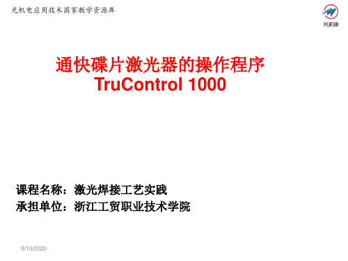
图3 TruControl 1000的激光程序编辑界面
9/30/2018
2.5 给光路编程
涉及到光路方面,在TruControl 1000下可以进行以下工作:(1) 给光路编程 ;(2)选择光路;(3)管理光路。 给一个光路编程的含义是确定遮光器和转向器的反射镜在光学组件中的 位置。将反射镜位置信息存放在光路的数据组中。 TRUMPF通快公司已 将所有可能用于其激光器的光学组件上的光路进行了编程。每条光路均 用一条激光线缆通向加工位置。在使用光学组件时,可能两条或更多激 光线缆属于一条光路。 需要指出,光路编程工作由 TRUMPF公司的维修服务人员(用户 等级70 以上)负责。只有当激光器的光学组件有变动时才有必要编程, 以便 可以使用其它光路,或取消当前使用的光路。
9/30/2018
图3 TruControl 1000的脉冲形状编辑界面
2.4 创建激光程序
激光程序是指起动后能自动执行指令和设定的序列。 在 TruControl 1000 中 集成了一个激光程序编辑器,如图4所示。因此可以建立 激光程序,并对其进行 修改和管理。激光程序可按如下方式调出:(1 )通过手动操作;( 2)从外部 通过激光器接口。
25给光路编程472019小结本次课介绍了通快碟片激光焊接系统的代表性激光器trudisk2001的操作程序trucontrol1000的初步应用特别是对脉冲形状的编辑和激光程序的创建
通快碟片激光器的操作程序 TruControl 1000
课程名称:激光焊接工艺实践 承担单位:浙江工贸职业技术学院
9/30/2018
9/30/2018
3. 小结
本次课介绍了通快碟片激光焊接系统的代表性激光器 Trudisk2001 的操作程序 TruControl1000 的初步应用,特别 是对脉冲形状的编辑和激光程序的创建。
通快激光切割机trulaser3030

微连接
微焊接
切断
从图纸到零件
CAD DXF DWG IGES 格式的图纸
Trutops格式图纸 (.GEO)
主文件(.LST)
分解
TRUMPF Group
工艺 参数
主程序
子程序
机床加工
关于通快培训中心
TRUMPF Group
目录
1、课程介绍及说明 2、基础知识 3、机床操作技巧 4、改善切割切割技巧
TRUMPF Group
课程介绍
▪ 学习的目标: 1、能够独立操作机床完成作业 2、了解改善切割质量的方法
▪ 学习的时间 5天
▪ 日程安排
▪ 联系方式 手机: 邮件:
TRUMPF Group
工作经历介绍
▪姓名: ▪所在公司: ▪工作经历: ▪操作机床经验: ▪对课程的期望和愿望:
TRUMPF Group
完成该课程,掌握的内容
TRUMPF Group
▪ 开关机床 ▪ 机床操作(MMC操作面板) ▪ MDA ▪ 开关元素操作 ▪ 装卸激光头 ▪ 清洁切割镜片 ▪ TAPE-SHOT操作及条件 ▪ FOCUS-COMB操作及条件
▪ 混合比列
CO2:N2:He 1:4:5
吸收CO2多余能量,冷却系统 将其转为热量
机床结构
激光发生器
控制面板
TRUMPF Group
防护罩壳
安全门
光栅
机床结构
RF发生器控制柜 冷却系统 除尘系统 开关柜 激光发生器
TRUMPF Group
纵向传送带
交换工作台
坐标轴定义
工作区域 Overshoot
反射镜
RF发生器
TRUMPF Group
倍福beckoff编程手册精编版

目录
第2页
4.8 梯形图编辑器..........................................................................................................................132
4.9 连续功能图编辑器 ..................................................................................................................137
自动化技术
TwinCAT PLC 编程手册
德国倍福电气有限公司 2005 年 5 月
目录
第1页
目录
1 TwinCAT PLC Control 简介...............................................................................................................1 1.1 引言............................................................................................................................................1 1.2 项目组件.....................................................................................................................................3 1.3 语言..........................................................................................................................................10 1.3.1 编程语言............................................................................................................................10 1.3.2 指令表 (IL) ........................................................................................................................10 1.3.3 结构化文本(ST) ............................................................................................................12 1.3.4 顺序功能图(SFC)..........................................................................................................17 1.3.5 功能块图(FBD) .............................................................................................................21 1.3.6 连续功能图编辑器(CFC)...............................................................................................21 1.3.6 梯形图(LD) ...................................................................................................................22 1.4 调试,联机功能 ........................................................................................................................24
通快激光切割机trulaser 培训教材

输出气体
激光束
模式
输入气体
激光的发生气体
TRUMPF Group
激光发生气体有别于切割 气体
激光发生气体组成: 氮气N2
RF发生器产生的能量首先激发N2 ,使其处于跃迁状态
二氧化碳CO2 氦气He
处于跃迁状态的N2,激发CO2 ,使CO2跃迁,释放激光
混合比列
CO2:N2:He 1:4:5
吸收CO2多余能量,冷却系统 将其转为热量
尘
洁证 工 作 区 清
设
激光加工的过程
TRUMPF Group
1
2
8 A
3
7
T
B
C
4
6
5 1、透镜
2、激光束
A:空走高度
3、气流
4、拖后线
B:穿刺高度
5、熔融材料 6、切割面
7、喷嘴
8、切割方向
C:切割高度 T:板材厚度
通快激光工艺介绍
TRUMPF Group
FocusLine
核心部件通过水压调节 镜面的曲率,从而改变 激光束的发散角度,最 终调整激光焦点上下移 动
材料
切割速度 焦点位置
切割不良
激光质量
镜片
喷嘴
切割气体
切割气体
( 按
激
火焰燃烧切割 切割气:氧气/O2
切光
割切
气 体 分 类
割 类 型
)
熔融切割 切割气:氮气/N2
其他
TRUMPF Group
切割厚度大 切割速度快 切割断面有氧化层 切割断面有后拖线
切割断面无氧化层 切割毛刺较少 切割气体耗费大 切割速度慢 部分规格材料穿刺时 需要氧气参与
机床结构
3.15 通快碟片激光器的操作程序TruControl 1000讲解

图3 Tru2018
2.5 给光路编程
涉及到光路方面,在TruControl 1000下可以进行以下工作:(1) 给光路编程 ;(2)选择光路;(3)管理光路。 给一个光路编程的含义是确定遮光器和转向器的反射镜在光学组件中的 位置。将反射镜位置信息存放在光路的数据组中。 TRUMPF通快公司已 将所有可能用于其激光器的光学组件上的光路进行了编程。每条光路均 用一条激光线缆通向加工位置。在使用光学组件时,可能两条或更多激 光线缆属于一条光路。 需要指出,光路编程工作由 TRUMPF公司的维修服务人员(用户 等级70 以上)负责。只有当激光器的光学组件有变动时才有必要编程, 以便 可以使用其它光路,或取消当前使用的光路。
TruControl 1000中创建好激光程序后如何调出使用?
9/30/2018
9/30/2018
3. 小结
本次课介绍了通快碟片激光焊接系统的代表性激光器 Trudisk2001 的操作程序 TruControl1000 的初步应用,特别 是对脉冲形状的编辑和激光程序的创建。
9/30/2018
4. 作业思考题
(1)通快碟片激光器Trudisk2001的操作程序TruControl 1000的主要功能是什么? (2)简要说明在碟片激光器Trudisk2001的操作程序
9/30/2018
图1 TruControl 1000的光路选择界面
当然也可以利用程序TruControl 1000来更改光路,(如图2:TruControl 1000 的光路更改界面所示),选择工艺后选定光路,选择更改,出现编辑光路对话框, 选择按钮更改名称,完成并保存即可。
图2 TruControl 1000的光路更改界面
2.1 选择光路
Trumpf通快编程手册5
例
N100 TC_TOOL_N0(“03100000”) 工具选择回转工具
N110 TC_TOOL_CHANGE
工具更换
N120 X20 Y40 C1=DC(0)
行至始点
N130 NIBBLE_ON
步冲开通
N140 G03 J10 SPN=9
路径分配,步冲路
径(圆弧)
N150 NIBBLE_OFF
步冲关断
编程
M30
● 产生仅限本块的操作 ● 使所有加工功能断开选择 ● 取消 TC_SUCTION_ON(真空吸屑系统)
例
N100 PUNCH_OFF
冲关断
N110 TC_PART_UNLOAD(“ PAU-1”) 工件排出
N120 TC_SHEET_UNLOAD(“ SHU-1”) 废料架卸料
N130 M30
编程
M01 ● 产生仅限本块的操作 ● 只 有 在 控 制 系 统 的 用 户 界 面 中 在 “ Program
influence ”下选择了“ Progr.Stop ”方才执 行 ● 被按 START 钮取消
2. 程序结束
2.1 M02
定义 程序结束主程序
编程
主程序用 M02 结束,复位至程序开头。 M02 ● 产生仅限本块的操作 ● 使所有加工功能断开选择 ● 取消 TC_SUCTION_ON(真空吸屑系统)
编程
M00 ● 产生仅限本块的操作 ● 使所有加工功能断开选择 ● 被按 START 钮取消
用途
从编程系统产生的 NC 程序中不再有 M0环 内,例如在废料取出的“TC_PART_UNLOAD”内。
现在是人工加一 NC 程序的“停止”时才用 M00,例 如当 ● 程序试运转时 ● 测量和试验时
Trumpf通快编程手册6
第六章冲加工循环1 1.1 1.2 2 2.1 2.2 3 3.1 3.2 4 4.1 4.2 5 5.1 5.2 使 C 轴同步 TRAILON TRAILOF 冲 PUNCH_ON PUNCH_OFF 步冲 NIBBLE_ON NIBBLE_OFF 路径分配 SPP SPN 冲带延迟 PDELAY_ON PDELAY_OFF冲加工环16 6.1 6.2 7 7.1 7.2 8 8.1 8.2 9 9.1 9.2 10 10.1 10.2冲用压脚 PRESSERFOOT_ON PRESSERFOOT_OFF 真空吸屑系统 TC_SUCTION_ON TC_SUCTION_OFF 螺纹加工(选项) TC_TAP_ON TC_TAP_OFF 雕刻(选项) TC_MARK_ON TC_MARK_OFF 快速压筋(选项) TC_BEAD_ON TC_BEAD_OFF冲加工环21. 使 C 轴同步 1.1 TRAILON定义 语言命令 TRAILON 界定又同时激发 C1 (工具适配 器的回转轴)和 C2(下模适配器的回转轴)的同步。
注意: TRAILON 必须放在主程序开头紧跟程序标 题后的第一条命令! 编程 为使二回转轴同步,一轴必须作为主动轴处理,另 一轴作为从动轴。
主动一从动系统用下列参数界定: TRAILON (从动轴,主动轴) TRAILON ● 产生模态操作 ● 必须放在主程序开头紧跟程序标题后的第一条 命令 ● 被 TRAILOF 取消 ● 所有主动一从动系统编程的运动,在 TRAILON 之后只需对主动轴(C1)发命令,C2 自动同步地 执行所有运动。
从动轴 下模适配器的回转轴(C2)界定为从动轴。
所有为主动 轴(C1)编程的运动,全都同时被从动轴执行。
工具适配器的回转轴(C1)界定为主动轴。
运动均编程 给主动轴,从动轴(C2)同时进行全部运动。
主动轴冲加工环3例 N10 N20 N30 N40 . . N120 N130 N140 N150 N160 MSG(“ MSG(“ MSG(“ MSG(“ 主程序号,P1000 ”) TOPS 250 版本… ”) 日期 - … ”) 板材尺寸:…”)MSG(“ *** 正方形 10—110.00 *** ”) TRAILON (C2,C1) F108000 G01 TC_CLAMP_CYC1.2 TRAILOF定义 语言命令 TRAILOF 使 C1(工具适配器的回转轴)和 C2(下 模适配器的回转轴)的同步关系解除。
通快激光编程手册中文教材

TRUTOPS编程手册LASER程序设计手册Hanbo2009-12-27前言TRUTOPS是德国创普公司为TC机台开发的专用自动软件,其功能在自动应用方面极为强大,是自动冲孔机软件的完美化身,具有全新典型的TRUMPF标,该软件具有精确度高,排版自动化,排刀手动自动相结合及排刀不受刀位角度限制等优点。
为了使受训人员在短时间内,快速有效的掌握本软件,以及配合现场加工的要求,本版采用大幅插图的形式介绍了TRUTOPS软件的各项应用模块,其中LASER模块是本软件的重点,初学者需用心研究,力求掌握之纯熟境界。
目录一、TRUROPS软件CAD模块基本命令的应用 (1)二、DXF文档转换为GEO文档 (6)三、TRUROPS软件NEST模块基本命令的应用 (7)四、TRUROPS软件LASER模块基本命令的应用 (11)五、编程注意事项 (17)一.打开TRUTOPS如下图点击CAD图标,即可进入绘图模块,所示画面如下:1.CAD模块主要用于简单图形的绘制和修改,基本功能与CAD软件相同,这里我们只做简单的介绍,基本图标功能如下:1.1.删除图素1.2.删除选择(在这里面可以有条件的选取自已想要去除部分包括颜色,线型,和其它的几何图形)1.3.删除外轮廓1.4.删除小轮廓(在这里可以设定面积小于多少的轮廓一次性删除)1.5.删除短图素(在这里可以设定长度小于多少的图素一次性删除) 1.6.删除特征1.7.删除标注(图标变暗不可用)1.8.删除辅助线1.9.创建点1.10.两点创建一条直线1.11.创建水平线1.12.创建垂直线1.13.创建矩形1.14.用圆心和直径创建圆1.15.用圆心,起始角度,结束角度创建圆弧1.16.创建文字1.17.创建矩形形棱角缺口1.18.创建方形棱角缺口1.19.创建尖形图素缺口1.20.创建矩形图素缺口1.21.创建缺口沉切1.22.创建矩形棱面1.23创建方形棱面1.24创建棱角倒角2.此工具栏从左到右各图标功能如下2.1.退出TRUTOPS软件2.2.显示尺寸标注2.3.显示开放点2.4.显示全部点2.5.显示突出特征2.6.刷新2.7.全视图(CTRL+T)2.8.详图(局部放大)2.9.显示上次视图2.10.记忆视图2.11.调取视图2.12-2.18为各种尺寸测量3.下面为做图辅助线命令3.1.通过两点创建辅助线3.2.创建平行辅助线3.3.创建水平辅助线3.4.创建垂直辅助线3.5.过一点或借助角创建辅助线3.6.创建垂直辅助线3.7.创建辅助线使与X轴间成给定角度3.8.创建辅助线使与直线成X角3.9.创建辅助线使与2条圆弧线相切3.10.创建分度3.11.通过3个点创建辅助圆3.12.用圆心和半径创建辅助圆3.13.用直径创建辅助圆3.14.用圆心和直径创建辅助圆3.15.创建辅助同心圆3.16.在2条切线处并通过一点创建辅助圆3.17.通过2个点创建辅助圆与一直线相切3.18.创建辅助圆使其与3条直线相切3.19.用圆心创建辅助圆使其与一条直线相切4. 在打开界面的右边是工具导航栏:有创建,修改,尺寸标注,折弯,助手五部分在左侧面,但这里我们直正能用到的只有创建和修改两部分,创建部分主要是创建简单的线,圆,弧,棱角。
德国安舍编程说明书v2.0(英文版)
Operating manual for detector software 92GRAF version 2.0 or higherContents1 Introduction.................................................................................................1 - 31.1 Installation...........................................................................................1 - 42 Start of the program and operation............................................................1 - 53 The menu “Control“....................................................................................1 - 73.1 The menu “Interrogation“...................................................................1- 103.2 The menu “Measure“.........................................................................1 - 143.3 The menu “Memory“.........................................................................1 - 253.4 The menu “Rel./LED“....................................................................... 1 - 273.5 The menu “Ring“.............................................................................. 1 - 293.6 The menu “Test“................................................................................1 - 353.7 The menu “eT“..................................................................................1 - 363.8 The menu “Opt.“................................................................................1 - 423.9 The menu “End“................................................................................1 - 433.10 The menu “Help“.............................................................................1 - 43 Operating manuel service program 92TOOL......................................2 - 1Page 1 - 2 Detector software 92GRAF version 2.0 or higherIntroduction 1 IntroductionThis program is used for diagnoses. It allows the user to check the functionality and recognize the loop wiring. The program is also used for maintenance of detectors. It allows you to install and check a loop of 9200 series detectors without the fire alarm control panel. It is possible to delimit sources of errors. This program supports the analysis of an already installed loop and determines differences to the nominal. Errors in the wiring of the loop are easily to locate. If a file with the nominal loop wiring exists it is possible to initialize automatically from terminal "A" all detectors with increasing serial numbers. Together with wiring recognition a totally unknown loop can be initialized without any additional information. The expert system has also been implemented in this version of the 92Graf. The Expert system is used to check the functionality and the soil level of the intelligent fire detectors of the series 9200. This check can be performed on an entire loop, or on a single detector that is not installed. (Refer diagram 1).For safety reasons you should make a copy of this program and use this as your working disc. You should store theoriginal disc in a safe placeFor the chronological set up and specific evaluation of the files for protocols and archives it is necessary that thesystem date and time is set to the correct values..Detector software 92GRAF version 2.0 or higher Page 1 - 3Installation1.1 InstallationRequirements•IBM compatible PC•Operating system MS-DOS V3.3 or higher or Windows•VGA graphical adapter•Parallel port (e.g. LPT1 or LPT2)•Floppy 3½"/1,44 MBThe operation can be done either with the keyboard or the mouse.InstallationConnect the Interface with the parallel port of the PC and the power supply. The connection to the base of the detector is done by a 9 pin D-Sub connector. A connection to a loop is done by the Test adapter (Part No.: 789807).Fig. 1 : InstallationPage 1 - 4 Detector software 92GRAF version 2.0 or higherDetector software 92GRAF version 2.0 or higher Page 1 - 52Start of the program and operationType92GRAFGB.EXEon the DOS screen to start the program.The program automatically checks the connection between the in-terface and the parallel port (LPT1 or LPT2) of the PC.In case of an error the program will be terminated and possiblesources of the error will be shown.Fig. 2 : Error messageIf the program finds an interface the address of the parallel port will be shown on the screen.The operation of the program is orientated by the SAA standard. All functions of the program will be started by the pull down menus.Start of the programStart of the programAll menus can be selected either by the keyboard with the combi-nation of the character and the Alt-key or by using the mouse.The files for protocol and archives will be saved in the di-rectory of the 92GRAF. All files have a default name, andcan be changed to any valid DOS name.The files for the long term test will be saved in a separate directory:C:\ESSER\LONGTST\LONGTST.*Page 1 - 6 Detector software 92GRAF version 2.0 or higherDetector software 92GRAF version 2.0 or higher Page 1 - 73 The menu “Control“The menu "Control“ includes functions to interrogate or control thestatus of a detector.Fig. 3 : Menu “Control“ResetThis command is used to reset one or more detectors in a loop.The selection of a detector is done by the window "selection type address" (refer Fig. 8)Repet. status interrog.This command is used to start a repetitive status interrogation for all detectors on the loop. This command will be executed after input of the interval time. The status of the detector(s) will be shown in the window “loop status interrog“.The repetitive status interrogation can be terminated by any key.One-time status interrogThis command is used for a one-time status interrogation for all detectors on a loop. There will be no repetition of this command.Men “Control“Menu “Control“Conditions of detectorThe production data and information related to the environment of the chosen detector or transponder will be read. The Selection of the bus user is done by the short address.ReleaseThe status of a detector will be released. A new status will only be detected if a acknowledge (see below) followed by a release is done. The selection of a detector is done by the window "se-lection type address" (refer Fig. 8).AcknowledgeThe new-signal of a detector will be acknowledged. The status of the detector will only get detected again after it has been re-leased (see above). The selection of the acknowledge is done by the window " selection type address " (refer Fig. 8).Detector ONThis command turns on a detector. An analog measurement or an alarm will be possible. The selection of a detector is done by the window "selection type address" (refer Fig. 8).Detector OFFThis command turns off a detector. Analog measurements and decisions for an alarm are disabled. This detector will not be able to detect an alarm. After a reset all detectors will be automati-cally turned on. The selection of a detector is done by the win-dow "selection type address" (refer Fig. 8).Page 1 - 8 Detector software 92GRAF version 2.0 or higherMenu “Control“Loop-RESETThe loop will be dropped to 0V DC for a user defined period to reset all devices on the loop. The time for the reset is variable, it should be at least 10 seconds.After a reset the line voltage will be shown in the bottom of the screen.ReferenceUloop = Line voltageIL = Current measured on the loop by the interfaceUBatt = Voltage of the battery/accumulator in the interfaceLoop ⇒ UL_ZeroThe line voltage will be set to UL_Null.Loop ⇒ UL_LowThe line voltage will be set to UL_Low.Loop ⇒ UL_HighThe line voltage will be set to UL_High.Loop voltage variableThe signal levels of the loop (loop voltage and max. current) can be set to a specific value, e.g. as in a critical environment.The default values for a standard loop are:UL_Zero =0VUL_Low =9VUL_High=18VIL_High =60mADetector software 92GRAF version 2.0 or higher Page 1 - 9Page 1 - 10 Detector software 92GRAF version 2.0 or higher 3.1 The menu “Interrogation“The menu "Interrogation“ includes functions for the interrogation ofthe status of one, or a group of detectors.Fig. 4 : Menu “Interrogation“Show detector with status ...This function ‘Show detector with status ...’ shows all detectors with a specifically defined status. The search for a status will bedone by the window “detector status“.Fig. 5 : Box, detector status Menu “Interrogation“Search detector with status ...This command starts a search for a specific status of a detector on the loop. All detectors that are found will acknowledge thisstatus. A search can be done by the following new-signal.Fig. 6 : Box, search modeFind highest serial numberThe detector on the loop with the highest serial number and new-signal newstart will be found. The detector will acknowledge the new-signal newstart. The Selection is done by the window "selection type address" (refer Fig. 7).Search all serial numbersAll detectors on the loop with the new-signal newstart will be shown. The status newstart will be acknowledged. The Selection is done by the window "selection type address" (refer Fig. 7).The indication will be in a diagram with serial number and de-tector type.Only the detectors or transponder with the status newstartwill get detected. All detectors that have already acknowl-edged the status newstart will not be found.Menu “Interrogation“End-det. interr.This command is used to interrogate the status of one or more end-detectors in the loop or the spur. The Selection is done bythe window "selection type address".Fig. 7 : Box, selection type address.Status isolatorThis command is used to interrogate the status of one or more isolators in the loop. The status (open/close) will be shown. The Selection is done by the window "selection type address" (refer Fig. 7).Static statusThis command shows the last status that did not get acknowl-edged, independent of a new status, of a detector or a group of detectors. The Selection is done by the window "selection type address" (refer Fig. 7).Detector statusThis command is used to interrogate the status of one, or a group of detectors. The Selection is done by the window "selec-tion type address" (refer Fig. 8).Menu “Interrogation“Fig. 8 : Box, selection type address.Trouble statusThis command is used to show the trouble status of one or more detectors in decoded form. The Selection is done by the window "selection type address" (refer Fig. 8).Vector meas.This command is used to check the communication of all detec-tors in a loop. In addition it is also possible to check the topology of the loop. Every detector takes a separate measurement and stores the result which can be checked with “Analysis of vector meas.“. The Selection is done by the window "selection type ad-dress" (refer Fig. 7).Analysis of vector meas.This command is used to evaluate the vector measurement. all required information out of EEPROM and the result of the last measurement will be shown. The Selection of the detector will be done by the short address.Menu “Interrogation“3.2 The menu “Measure“The menu "Measure" includes functions to start a repetitive meas-urement or an analysis of one or all detectors on a loop.Fig. 9 : Menu,“Measure“Sensor measuringThis command is used for an analog measurement by short ad-dress. The time for the interval should not be less than 2000 ms.The measurements of the sensors will be shown in hex and can be stored in a file. The default name for the file is WERTE.DAT.Fig. 10 : Sensor measuring, I-Intelligent Fire Detector (example)Menu “Measure“Analog values & level graphicsThe values of the detector and the sensors will be read repeti-tively and will be shown in a level graphic.The detector will stop the internal analysis when the sum of the signals and the current measurement are larger than the alarm level (status FIRE). A renewed correct graphical diagram of the measurement will only be shown after a reset of the detector.Please use the key ‘R’ to reset the detector.Fig. 11 : Analog values & level graphics, OTI-Intelligent Fire Detector (example)Esc Return to main menu R Reset of the detector Menu “Measure“Detector dataThis window shows the detector data out of the EEPROM.Fig. 12 : Detector data, OTI-Intelligent Fire Detector (examplel)Detector typeShows the type of the detector.Manufacture dateShows the production date of the detector.Serial numberShows the serial number of the detector.Last maintenance workShows the date of the last maintenance work for this detector.Menu “Measure“Sensor status indicationThis window shows in dependency of the sensors in the detector the current measurement and the sum of the signals.An alarm will be indicated as soon as the sum of the signals [∑]or the current measurement [a] of one sensor will be larger thanthe alarm level [AL].Fig. 13 : Sensor status indication, OTI-Intelligent Fire Detector (Example)The following graphics will be shown in the window sensor status indication:O= optical sensor T= thermo sensor I= Ionization sensor ∑ = sum of the sensorsLegend of the sensor status indicationa: act. valueshows the current measurementw: warn. rangeshows the critical area for the quiescent valuesel: electr. Working rangeshows the critical area for the current measurement Menu “Measure“R: corrected quiescent valuesshows the quiescent value of the sensor in the environment of the detector*: birth valueshows the birth or production value of the detectorVAL: Pre-alarm levelshows the pre-alarm level of the sum signalAL: Alarm levelshows the alarm level for the sensor or the sum signal Current statusthis window shows the current status of the detectorFig. 14 : Current status, OTI-Intelligent Fire Detector (example)Hours of operationShows the hours of operation.detector nShows the short address and the current status of the detec-tor.Pre-alarm counterShows the counter of detected pre-alarms.Alarm counterShows the counter of detected alarms.Soil levelshows the soil level of the detector in percentage Menu “Measure“Standardized graphicsIn the standardized graphics all standardized sensor measure-ments (e.g. O-, T- and I-sensor) of the detector will be shown in a graphic.The duration of the measurement can be selected between 1, 2,4 or 8 minutes.The Selection of the detector is done by the short address. De-pending on the type of detector, the measurements of the sen-sors will be shown in graphics. In addition to the measurements of the sensors the total sum signal, the pre-alarm and alarm level will be shown. As soon as the sum of the signals is larger thanthe pre-alarm or alarm level the detector will have this status.Fig. 15 : Standardized graphics, OTI-Intelligent Fire Detector (example)Menu “Measure“Absolute graphicsIn the absolute graphics mode all absolute sensor measure-ments (e.g. O-, T- and I-sensor) of the detector will be shown in graphics.The duration of the measurement can be selected between 1, 2,4 or 8 minutes.The Selection of the detector is done by the short address. De-pending on the type of detector, the measurements of the sen-sor will be shown in graphics.Fig. 16 : Absolute graphics, OTI-Intelligent Fire Detector (example)Menu “Measure“Load standardized graphicFor diagnoses and valuation it is possible to load a standardized graphic. The extension of files with standardized graphics is *.REL .Load absolute graphicFor diagnosis and valuation it is possible to load a absolute graphic. The extension of files with standardized graphics is *.ABS .Expert system loopThe Expert system loop is used to check the functionality and the soil level of all detectors in a loop. The result will be stored in a file. The default name for the file is LOOPXXX.MSG .The result of the test will also be shown on the screen.Fig. 17: Expert system loop (example)Menu “Measure“Expert System for one detectorThe expert system for one detector works the same way as the “expert system loop“. The result of the test will be stored in a file.The default name for the file is LOOPXXX.MSG .The Selection of the detector will be done by the short address.During the test the detector will be intensively checked. The re-sult and additional information about required steps to take will be shown on the screen.After cleaning the detector the function “cleaning control“has to be started in order to guarantee the functionality of the detector.Cleaning checkPlease make sure that there is only one detector connected to the interface when using the function cleaning check. This func-tion is also only to be used for detectors that have been marked as dirty by the expert system. The detector has to be cleaned before starting the cleaning control.The cleaning control has to be done in a clean environment without interference to the environment, e.g. draught, high tem-perature, direct sunbeam or exceptionally high humidity.Fig. 18: Cleaning check (example)Menu “Measure“Long term test det.The long term test can be very helpful to check the exact func-tionality of a specific type of detectors in a critical environment.Possible irregularity in a detector can be found in a long term test. The optimum detector for a specific environment can be easily determined.There should be only one detector on the loop during the longterm test.Fig. 19 : Long term test det.The information of the long term test will be stored in a separate directory. This directory will be created automatically if it does not exist.C:\ESSER\LONGTST\LONGTST.*Already existing files in this directory should be stored on adisk. All existing files will be overwritten by the start of the long term test Menu “Measure“Menu “Measure“The following files will be created by the long term test.LONGTST.BINThe analog measurements and the status of the detector will be stored in binary format in this file.LONGTST.INFThis file contains information about the parametric of the de-tector and the time of the test.LONGTST.STKStatistics will be stored in this file.LONGTST.ANZThe counts of each measurement will be stored in this file.The evaluation of these files can be done with a macro for Mi-crosoft® Excel.3.3 The menu “Memory“The pull down menu "Memory" includes functions to read or store information in the memory of the detector. The Selection of the de-tector is done by the window "selection type address" (refer Fig. 7).Fig. 20 : Menu “Memory“Read total EEPROMAll banks of the EEPROM (bank 1, 2, 3 and 4) will be read. The information will get stored in a file. The default name of the file is EEPANA.GES .Read EEPROM bankOne bank, 1-4, of the detector will be read. The values are shown with an explanation for each register. The banks of the EEPROM are organized as follows:- EEPROM bank 1detector parameter - EEPROM bank 2detector parameter - EEPROM bank 3Trouble counter / clock - EEPROM bank 4Production data Menu “Memory“Menu “Memory“Read EEPROM-RegisterOne register (0-63) will be read and put on the screen with an explanation. Some registers will get shown in a decoded format(e.g. register 3)Read RAM cellThe value of the chosen RAM cell will get shown on the screen.New short addressThis command allows you to give a detector a new short ad-dress. The Selection of the detector is done by the window "se-lection type address". The new short address must be in a range from 0 to 127.New address fieldThis command allows you to send a new address field to a de-tector.The address field is arranged by 4 different groups:- control group (0-15)- group number (1-15)- isolator detector number (1-15)- End detector number (0-15)Program versionThis command will read the version of the firmware of a detector or Transponder.3.4 The menu “Rel./LED“The pull down menu "Rel./LED" includes functions to test and con-trol the external relay, isolator, external LED and the visible LED.The Selection of the detector is done by the window "selection typeaddress" (refer Fig. 7).Fig. 21 : Menu “Rel./LED“Open isolatorThis command is used to open an isolator in the base of a de-tector or on the isolator board of a transponder.Close isolatorThis command is used to close the isolator in the base of a de-tector or on the isolator board of a transponder.Menu “Rel./LED“Menu “Rel./LED“Remote output -> normalThis command turns the remote output in the base of the detec-tor in the normal mode.Remote output -> activeThis command turns the remote output in the base of the detec-tor in the active mode.Internal LED -> normalThis command is used to start communication with a detector ora Transponder via the non-visible LED.Activate LEDsThis command is used to start communication with a detector ora Transponder via the internal LED. The communication can beverified by the visible LED.LED ActivationThis command will periodically activate the LED's of all detectors that have the internal LED in the active mode. This function is helpful to find detectors with the same short address or to de-termine a break.Send data via int. LEDThis command is used to turn on periodically the visible LED of a detector or transponder. The selection of the bus user is done by the short address. A short address between 128 and 255 will turn on periodically the LED's of all bus users.Analysis option. PCBThis function checks the relay board, isolator board or the exter-nal LED of the selected detector or transponder.3.5 The menu “Ring“The menu "Ring“ includes functions for the maintenance or the in-stallation of a loop.Fig. 22 : Menu “Ring“RestoreThis function will restore a loop, data in the detector (e.g. short address, group number) will not be destroyed. The short ad-dresses of all detectors that are ready for communication will be shown in a window. The first time a detector is ready for com-munication it’s serial number and detector type will be shown.The loop will be continuously build up and checked for possible shorts. The sum of all detectors with alarm, pre-alarm and trou-ble will be shown. The short addresses of these detectors will be marked in different colors. Multiple short addresses will be de-tected as well. The LED of the detectors that are ready for com-munication will flash to make a visible check of already initialized detectors easier. Please press Esc to terminate this of loopThis command is used to load a file that is used as a reference for the following functions. This file is used as a nominal. The actual is determine during the wiring recognition and is com-pared with the nominal.Menu “Ring“Wiring recognitionThis function will determine the actual wiring.Fig. 23 : Wiring recognition (example)A comparison between the actual and the nominal wiring will be done if there is any valid information in the file for reference.Differences in the types of detectors, the external circuits and the wiring will be shown on the screen as well as being saved in an archive. The information in the file for reference will be stored in the detectors (e.g. short address). The file for the archive will have the same name as the file for reference except that the extension is *.TEL . The file for the archive can be used for fur-ther analysis.If the wiring recognition or the control of loopwiring is used with-out a file for reference, all information will be saved in text form in a file with the extension *.GFK . Also a LINIE_1.REF will be created for later reference. The short addresses will be auto-matically set.Menu “Ring“92G R A F G B.E X E p r o g r a m v e r s i o n:d a t e:04.09.1997t i m e:9:38R e f e r e n c e f i l e f o r l i n i eN a m e o f l i n i e:L i n i e_1C a r a d o n E S S E R G m b H.P a r a m e t e r f o r d e t e c t o r t y p e(#)1O T I d e t e c t o r(4D)2O T d e t e c t o r(3D)3I d e t e c t o r4T1M A X d e t e c t o r5T2M A X d e t e c t o r6T D I F F d e t e c t o r7O d e t e c t o r8e s s e r b u s t r a n s p o n d e r R E L129e s s e r b u s t r a n s p o n d e r R E L610e s s e r b u s t r a n s p o n d e r A E3211e s s e r b u s t r a n s p o n d e r4G_2R E L12e s s e r b u s t r a n s p o n d e r I O_T A L13D d e t e c t o r14e s s e r b u s t r a n s p o n d e r I O_A D15U V/I R d e t e c t o rP a r a m e t e r f o r w i r i n gS d e t e c t o r i n s p u rR d e t e c t o r w i t h e x t e r n a l r e l a yT i s o l a t o r d e t e c t o rZ d e t e c t o r w i t h p a r a l l e l d i s p l a yE e x t e r n a l w i r i n gI1I/O c a r d n u m b e rM M1M i c r o m o d u l n u m b e r G0,M1G0, G0, G0, G0, G0, G0, G0, G0, G0, G0, G0, G0,G0, G0, G0, G0, G0,G0, G0, G0, G0, G0, G0, G0,M2M3M4M5M6M7M8M9M10M11M12M13M14M15M16M17M18M19M20M21M22M23M24M25,#7,,#7,,#7,,#7,,#7,,#7,,#7,,#2,,#7,,#7,,#7,,#7,,#7,,#2,,#7,,#2,,#7,,#2,,#7,,#13,,#13,,#13,,#13,,#13,,#13,TTTTTTTTTS TS TS TS TS TS TS TTTTTTT12345678910111213141516171819202122232425g r o u p n u m b e r i n c o n t r o l p a n e ld e t e c t o r n u m b e r i n g r o u pd e t e c t o r t y p e(a b o v e-m e n t i o n e d)w i r i n g(a b o v e-m e n t i o n e d)s h o r t a d d r e s sd e t e c t o r a d d i t i o n a l t e x t""""""""""""""""""""""""""""""""""""""""""""""""""r e f.-d e t e c t o rFig. 24 : Reference file for line_1 (example)A manual call point station in alarm has to be connected toterminal ‘B’ of the loop to determine unambiguous a spurand the end of the loop.Menu “Ring“Control of loopwiringThis function is used to start a comparison between the actual and the nominal loop wiring. No data in the detectors will be changed , even if the actual wiring is different than the nominal.Wiring displayThe wiring display can only be used after a successful wiring recognition. This function is used to show a graphical loop wir-ing.A part of the loop will be shown on the screen.Fig. 25 : Wiring display (example)The keyboard can be used to scroll through the loop and to show different information about the detectors.Menu “Ring“KeyFunctionOne detector up.One detector down.One detector left.One detector right.Pos1Goes to terminal “A+“, “A-“EndeGoes to terminal “B+“, “B-“1Shows loop or spur position of the de-tectors2Shows the serial number and the type of the detectors3Shows the short address of the detec-tors.4Shows the group number of the detec-tors.5Compares the default to the current in-stallation.EscReturns to main menu.Menu “Ring“。
- 1、下载文档前请自行甄别文档内容的完整性,平台不提供额外的编辑、内容补充、找答案等附加服务。
- 2、"仅部分预览"的文档,不可在线预览部分如存在完整性等问题,可反馈申请退款(可完整预览的文档不适用该条件!)。
- 3、如文档侵犯您的权益,请联系客服反馈,我们会尽快为您处理(人工客服工作时间:9:00-18:30)。
TRUTOPS编程手册LASER程序设计手册
Hanbo
2009-12-27
前言
TRUTOPS是德国TRUMPF公司为机床开发的专用自动软件,其功能在自动应用方面极为强大,是激光切割软件的完美化身,具有全新典型的TRUMPF标,该软件具有精确度高,排版自动化,排刀手动自动相结合及排刀不受刀位角度限制等优点。
为了使受训人员在短时间内,快速有效的掌握本软件,以及配合现场加工的要求,本版采用大幅插图的形式介绍了TRUTOPS软件的各项应用模块,其中LASER模块是本软件的重点,初学者需用心研究,力求掌握之纯熟境界。
目录
一、TRUROPS软件CAD模块基本命令的应用 (1)
二、DXF文档转换为GEO文档 (6)
三、TRUROPS软件NEST模块基本命令的应用 (7)
四、TRUROPS软件LASER模块基本命令的应用 (11)
五、编程注意事项 (17)
一.打开TRUTOPS如下图
点击CAD图标,即可进入绘图模块,所示画面如下:
1.CAD模块主要用于简单图形的绘制和修改,基本功能与CAD软件相同,这里我们只做简单的介绍,基本图标功能如下:
1.1.删除图素
1.2.删除选择(在这里面可以有条件的选取自已想要去除部分包括颜色,线型,和其它的几何图形)
1.3.删除外轮廓
1.4.删除小轮廓(在这里可以设定面积小于多少的轮廓一次性删除)
1.5.删除短图素(在这里可以设定长度小于多少的图素一次性删除) 1.6.删除特征
1.7.删除标注(图标变暗不可用)
1.8.删除辅助线
1.9.创建点
1.10.两点创建一条直线
1.11.创建水平线
1.1
2.创建垂直线
1.13.创建矩形
1.14.用圆心和直径创建圆
1.15.用圆心,起始角度,结束角度创建圆弧
1.16.创建文字
1.17.创建矩形形棱角缺口
1.18.创建方形棱角缺口
1.19.创建尖形图素缺口
1.20.创建矩形图素缺口
1.21.创建缺口沉切
1.2
2.创建矩形棱面
1.23创建方形棱面
1.24创建棱角倒角
2.此工具栏从左到右各图标功能如下
2.1.退出TRUTOPS软件
2.2.显示尺寸标注
2.3.显示开放点
2.4.显示全部点
2.5.显示突出特征
2.6.刷新
2.7.全视图(CTRL+T)
2.8.详图(局部放大)
2.9.显示上次视图
2.10.记忆视图
2.11.调取视图
2.12-2.18为各种尺寸测量
3.下面为做图辅助线命令
3.1.通过两点创建辅助线
3.2.创建平行辅助线
3.3.创建水平辅助线
3.4.创建垂直辅助线
3.5.过一点或借助角创建辅助线
3.6.创建垂直辅助线
3.7.创建辅助线使与X轴间成给定角度
3.8.创建辅助线使与直线成X角
3.9.创建辅助线使与2条圆弧线相切
3.10.创建分度
3.11.通过3个点创建辅助圆
3.12.用圆心和半径创建辅助圆
3.13.用直径创建辅助圆
3.1
4.用圆心和直径创建辅助圆
3.15.创建辅助同心圆
3.16.在2条切线处并通过一点创建辅助圆
3.17.通过2个点创建辅助圆与一直线相切
3.18.创建辅助圆使其与3条直线相切
3.19.用圆心创建辅助圆使其与一条直线相切
4. 在打开界面的右边是工具导航栏:有创建,修改,尺寸标注,折弯,助手五部分在左侧面,但这里我们直正能
用到的只有创建和修改两部分,创建部分主要是创建简单的线,圆,弧,棱角。
修改部分主要分移动,转动,刻度标(等同于CAD的比例放大),建立镜像,伸展(等同于CAD软件的拉伸),清理,图素几部分,移动转动刻度标和镜像几部分都包含复制功能,具体如下图
二.在本模块中我们的主要目的是把DXF文档转换为GEO格式,以便于后
续的编刀和排版,主要操作如下:
1.打开文件夹【命令】DXF文档,
2.点击【命令】图标查看是否有重复线或断线,如有重复线可用【命令】图标命令删除重
复线,断线用【命令】这两个图标的命令来使断线闭合
3.修改完成后点【命令】图标将图形另存为GEO格式.
三.点击NEXT图标进入组合排版界面,如下图所示
1.点击[命令]建立新任务单,会出现以下对话框,在[任务栏]输入需建立的任务单号码,[存储地点]输入储存位置(依个人习惯)
1.一切完成后点击OK出现以下对话框,在这里添加所需排版的工件
子
2.选取所需排版的工件后会出现以下对话框,这里需输入所要加工的件数及是否可任意旋转
3.下图为常规选项,如工件间距,板料边距及工件排料的起始角等
5.起动后会自动生成排版并保存为TAF,此模块主要是方便多种相同材料和板厚的工件进行套料时,更好的提高材料利用率
四、点击LASER图标即进入激光编程界面,如下图所示:
1.以上界面各图标用途从左到右依次为:
1.1.打开文件
1.2.打开文件并编辑
1.3.打开文件并准备(带TWINLINE的板料)
1.4.保存文件
1.5.用新名称保存文件
1.6.将所选零件作为为GMT(几何图形及工艺)保存
1.7.打开文件浏览器
1.8.打印屏幕内容
1.9.自动加工整个零件和板料
1.10.生成数控程序
1.11.自动创建生产信息包1.1
2.显示生产信息包
1.13.加工解禁
1.14.移动进刀位置
1.15.显示轮廓参数
1.16.应用轮廓参数
1.17.复制一个轮廓的加工1.18.设置微型连接
1.19.启动模拟
2.以上界面各图标用途如下:2.1.显示全部点
2.2.显示几何图形
2.3.显示定位点
2.4.显示数控循环
2.5.显示几何图形和工艺2.6.显示碰撞
2.7.显示缺少的倒角
2.8.显示机床0
2.9.显示支撑板
2.10.突出傾翻轮廓碰撞2.11.切换为工艺视图2.12.切换为数控视图
2.1
3.配置视图
2.14.更新图纸
2.15.全视图
2.16.板料全视图
2.17.局部视图
2.18.上一次视图
2.19.保存视图
2.20.打开视图
2.21.测量两点间距离
3.左侧为辅助线命令与前面CAD模块一样,这里就不再介绍
4.右边为导航工具栏具体命令有:配置,TWINLINE,工艺,优化和数控程序
配置分移动零件和零件组,基本功能如下图所示:
移动零件分移动和转动两种,零件组基本不用
5.TWINLINE主要是对于共边切割的零件使用的一种切能(如果是共边切割一定要先启动此功能,再进行切割启动)
6.工艺是激光加工的核心,主要功能分加工、修改、进程优化、轮廓参数、模具轨道、数控循环、
板料切边。
7.以上是LASER模块中的一些命令介绍,下面讲正常排版流程:
7.1.TAF文档,
7.2.点击图形全部生成激光切割,
7.3.,使之成为原始的直角
7.4.工件间间距较小时需检查切入点是否在切到别的工件,如有点击移动切入点到合适位置
7.5.,
7.6.,
7. 7.NC程序文件,即LST格式文件。
五、别附编程中应该注意的问题:
1.在TRUTOPS软件CAD模块将DXF格式转换成GEO时一定要注意检查图形中的断点和重复线,并做相应的修复,在保存时一定要注意不同版本之间标示区分。
以免造成GEO文件版本混乱,排版时调错文档的质量事故发生。
2.在排版时应注意根据材料厚度设定工件排版参数(包括排版的边距和工件间的间距)。
3.在激光自动切割时要注意检查激光切割引线方向是否正确,穿刺点是否正确(包括到边太近或两工件间太近造成加工另一工件时对前一工件有打缺现象)。
