UPS用户手册
SOCOMEC EGYS DB系列UPS 不间断电源 用户手册
第1章 重要安全注意事项
1.1. 禁止事项
1. 本产品非本公司或授权经销商之技术人员,请勿擅自开启机壳,否则 您的保证将会失效,且有触电的危险。
2. 产品内所有零件皆经检查及合乎高标准规格,未经授权之经销商或检 定合格专业人员及使用者,请勿自行修护及更换零件。
3. UPS 本体的上方禁止放置花瓶或装水容器,花瓶或装水容器倾倒会导 致水份进入机器内,容易产生触电、UPS 内部损坏之危险。
4. 本产品禁止使用于有火花、烟雾、瓦斯等现象之环境,以免导致跳火 (ARC)、受伤、火灾之危险。
2
3
1.2. 使用注意事项
1. 本产品的使用环境,及保存方法,对产品的使用寿命,及故障发生有绝 对的影响。因此,请特别注意避免下列工作环境使用: a. 避免在使用说明书内所记载以外(温度 0-40OC,相对湿度 30-90%), 之高温、低温、潮湿场所使用。 b. 有阳光直射场所。 c. 接近有热源之场所(因内部之电池受热会加速自我放电)。 d. 在振动、易撞击之场所。 e. 有火花产生之场所。 f. 有粉尘、具有腐蚀性物质、盐份、可燃性气体之场所。 g. 屋外。
2. 请保持进排气孔的通畅,进排气口请离墙壁 20 公分以上距离。进排气 孔的通风不良,会导致 UPS 内部温度升高,使得电池寿命减少。
3. UPS 使用的场所最好通风良好,建议应有每小时 5M3 之空气量,因充 电时电池之充电化学反应,会有微量气体产生,若电池又有破裂,容 易导致 UPS 内部跳火(ARC)。
软件安装........................................................................................... 21 硬件安装 ...................................................................................... 21 软件安装(安装完毕后请重新启动系统).................................... 21
UPS(山特)操作手册

UPS操作手册一、电气安全1.上电前,请确认已正确接地,并检查接线和电池极性的连接正确。
2.当UPS需要移动或重新接线时,应将交流输入电源断开,并保证UPS完全停机,否则输出端仍可能带电,有触电的危险。
3.请使用山特指定的附加装置和附件。
4.为了符合EMC的要求,UPS的输出线长度应在40米以内。
二、电池安全1.电池的寿命随环境温度的升高而缩短。
定期更换电池可保证UPS工作正常,并保证足够的后备时间。
2.蓄电池维护只能由具备蓄电池专业知识的人员来进行。
3.蓄电池存在电击危险和短路电流危险。
为避免触电伤人事故,在更换电池时,请遵守下列警告:A.不要佩带手表、戒指或类似的金属物体;B.使用绝缘的工具;C.穿戴橡胶鞋和手套;D.不能将金属工具或类似的金属零件放在电池上;E.在拆电池连接端子前,必须先断开连接在电池上的负载。
4.请不要将蓄电池暴露于火中,以免引起爆炸,危及人身安全。
5.非专业人士请勿打开或损毁蓄电池,因为电池中的电解液含有强酸等危险物质,会对皮肤和眼睛造成伤害。
如果不小心接触到电解液,应立即用大量的清水进行清洗,并去医院检查。
6.请不要将电池正负极短路,会导致电击或着火。
三、使用保养1.使用环境及保存方法对本产品的使用寿命及可靠性有一定影响,请不要在以下工作环境中使用:超出技术指标规定(温度0℃~40℃,相对湿度20%~90%)的高、低温和潮湿场所;有振动、易受撞的场所;有金属性粉尘、腐蚀性物质、盐份和可燃性气体的场所。
2.如果长时间放置不使用,必须将UPS(不带电池)存放在干燥的环境中,存贮温度范围:-25℃~+55℃。
UPS开机之前,必须先让环境温度回暖至0℃以上。
四、使用说明本UPS是一种先进的在线式正弦波不间断供电系统,可选带有手动旁路维护开关,具有并联冗余的功能,可以为您的精密设备提供可靠、优质的交流电源,其适用范围很广,从电脑设备、通信系统到工业自动控制设备都可以使用。
由于它的在线式设计,不同于后备式UPS,它对输入电压不断调整、滤波,在市电中断时,会无时间中断地从备用电池上提供后备电源。
UPS 操作手册完整版
接点
组件
解释
F021
逆变器输出保险
当逆变器发生重大故障时保护负载,当逆变器发生重大故障时系统将会切换到旁路,同时保险F021将会断开并不影响输出电压。前面板将会显示警报
A035
(A030)
静态旁路转换开关EN
具有3组不平行转换电源可控硅
A201
内部电源供应
由内部整流器主线或旁路主线供电,此供电是内部供电冗余系统的一部分与A202一起由电池供电,二者之中的每一个都可以充足为系统供电,当二者之中的一个发生故障,前面板将会将会发出警报
每一个并机系统是独立的,有其独立的旁路,除了输出配电柜,不再需要其他的共用组件或者中央部件
一个有问题的系统将会立刻与输出配电柜隔离
负载为各个独立的系统所分配供电
特性
产品特点
优点
冗于组件为并机冗于所使用(无公共故障点)
保证连续为负载供电
风扇监测
每一个独立的长寿命风扇由一个霍尔发生器监测(防尘)并且可以在线更换,不会对负载及人身造成危险
在此状态下负载由系统供电(逆变器或静态旁路)
TEST旁路主线供电,UPS系统可被检测,而用电设备可以在安全的母线工作
BYPASS在此状态下负载由旁路主线供电,UPS系统可被检测,而用电设备可以在安全的母线工作,要完全的隔离系统部分Q028,Q001,和Q004必须是断开的
X001
整流器主线端子
用于连接整流器主线(L1,L2,L3,PE)整流器主线输入已被保护,代替外部的保护设备保险管或断路器可以应技术需要而使用
滤波电抗器
与CB03一同过滤PWM的输出低级别
消除逆变变压器T002输的出非线性失真因素
线路交叉(网络)UPS 1000VA 1500VA 2000VA用户手册说明书

U P S U n i n t e r r u p t i b l e P o w e r S y s t e m Line Interactive (Network) UPS1000VA/ 1500VA/ 2000VA■USER‘S MANUAL■IMPORTANT SAFETY INSTRUCTIONS SAVE THESE INSTRUCTIONS●WARNING (SAVE THESE INSTRUCTIONS): This manual contains important instructions that should be followed during installation and maintenance of the UPS and batteries.●Intended for installation in a controlled environment.●Servicing of batteries should be performed or supervised by personnel knowledgeable of batteries and the required precautions. Keep unauthorized personnel away from batteries.●When replacing battery, replace with the same number and type.●CAUTION: Do not dispose of battery or batteries in a fire, the battery may explode.●CAUTION: Do not open or mutilate the battery or batteries. Released electrolyte is harmful to the skin and eyes. It may be toxic.●CAUTION: A battery can present a risk of electric shock and high short circuit current. The following precaution should be observed when working on batteries:Remove watches, rings or other metal objects.Use tools with insulated handles.Wear rubber gloves and boots.Do not lay tools or metal parts on top of batteries.Disconnect charging source prior to connecting or disconnecting battery terminals.I MPORTANT S AFETY I NSTRUCTIONS (2)T ABLE OF CONTENTS (2)I NTRODUCTION (3)1. P RESENTATION (3)2. I NSTALLATION (4)3. O PERATION (4)4. A LARMS (5)5. S OFTWARE AND I NTERFACE P ORT (5)A PPENDIX A. T ROUBLESHOOTING (7)A PPENDIX B. S PECIFICATIONS (7)Please read and save this manual !Thank you for selecting this uninterruptible power system (UPS). It provides you with a perfect protection for connected equipment. The manual is a guide to install and use the UPS. It includes important safety instructions for operation and correct installation of the UPS. If you should have any problems with the UPS, please refer to this manual before calling customer service.The UPS is a line interactive uninterruptible power system (UPS). When utility input is normal, the UPS would provide surge protection and energy to charge the internal battery. If the utility input is abnormal, the UPS can supply AC power to the load immediately.(1). Utilizes microprocessor based controls, it will minimizes the dependency on hardware. Beside this, it maximizes system flexibility and optimizes the assurance of reliability.(2). Automatic frequency selection to match with utility power.(3). Hi level battery charger to prolong battery’s life and fully charge the battery.1.1) Power Switch1.2) Remote Port (option) 1.3) Phone Jack (option) 1.4) Output Bypass 1.5) Outlet Socket1.7) AC Input1.8) AC Fuse/ Breaker2.1 Inspection: Inspect the UPS upon receipt. The packaging is recyclable; save it for reuse or dispose of it properly.2.2 Utility Power: The input power cord on the rear panel needs to plug into a socket on the wall. Please notice the voltage of utility power should match with the UPS. (For example, the UPS is 220V, the input utility power should be 220V as well.)2.3 Connection: The employed equipment’s power cords (such as computer) are plugged into the sockets on the rear panel.3.1 Switch on with “Green Mode” Function under AC mode: When utilityinput is connected to the UPS, press “ON” button and keep pressing less than 1 sec to turn on the UPS. After that, connect the electrical cords of the equipments that will be used (such as desktop computer and CRT monitor) to the rear panel of UPS. In order to save the power, it will also automatically enable the “Green mode” - No Load (or Light load) shut-down function under backup mode (about 4 minutes later).Attention: At backup mode, UPS can be automatically turned off if none of the connected loads is operating. (Green mode; No Load shut down function) Once the utility power is normal again, the unit can be waked up by itself.CAUTION: Never connect a laser printer or plotter to the UPS with other computer equipment. A laser printer or plotter periodically draws significantly more power than when its idle status, and may overload the UPS.3.2 Switch on with “Disabled Green Mode” Function under AC mode: When utility input is connected to the UPS, press “ON” button and keep pressing until the ”Bi……….Bi-Bi” beeps stopped to turn on the UPS. After that, connect the electrical cords of the equipments that will be used (such as Notebook computer and LCD monitor) to the rear panel of UPS. If the load is lighter than 15W, please also refer this function to avoid any inconvenience cause by “Green Mode” function.3.3 DC Start with “Green Mode” Function: If the power of UPS isn't supplied by utility but by the internal batteries to engage the UPS, press the power button and keep pressing less then 3 seconds.3.4 DC Start with “Disabled Green Mode” Function: If the power of UPS isn't supplied by utility but by the internal batteries to engage the UPS, press the power button and keep pressing until the sounds of “Bi…... Bi-Bi”.3.5 Switch off: Press the power switch and keep pressing more than 3 seconds toturn off the UPS.3.6 Silence: When UPS is under “BACKUP” mode, press power switch more than 1 second to silence the audible alarm. (The function is disable when UPS is under condition of “LOW BATTERY” or “OVERLOAD”)3.7 Self test function: Press power switch while utility power is connected, UPS will perform self-test procedure automatically.4.1 “BACKUP” (slow alarm): When the UPS is working under “BACKUP” mode, the UPS would emit audible alarm. The alarm stops when the UPS is return to “LINE” mode operation.Attention: The alarm of “BACKUP” is going to beep every 2 seconds. (Slow-speed beep).Attention: The UPS provides mute function for the warning. When the beeping sound occurs, press "ON" to stop it; and press "ON" again to regain the sound.4.2 “LOW BATTERY” (rapid alarm): In the “BACKUP” mode, when the energy of battery becomes to lower level. (about 20%~30%) The UPS beeps rapidly until the UPS shuts down from battery exhaustion or returns to “LINE” mode operation. Attention: The alarm of the batteries caused by low voltage beeps every 0.5 second.Attention: The rapid alarm under “LOW BATTERY” condition cannot be muted.4.3 “OVER LOAD” (continuous alarm): When the UPS is working under overload condition (the connected loads exceed the maximum rated capacity), the UPS will emit continuous alarm to warn an overload condition. In order to protect the unit and the loads, the UPS will be automatically turn off. Please disconnect nonessential devices from UPS to eliminate the overload alarm.5.5.1 Power Monitoring SoftwareThe UPS-MON series software (or other power monitoring software) is applied standard RS-232 interface to perform monitoring functions, and then provides an orderly shutdown of a computer in the event of power failure. Moreover, UPS-MON displays all the diagnostic symptoms on monitor, such as Voltage, Frequency, Battery level and so on. The software is available for DOS, Windows 3.1x, Windows 95, Windows 98, Windows NT V3.5 or later, Novell Netware, Linux, and others. Call your dealer for more information on computer OS compatible solutions. 5.2 Interface KitsA series of interface kits is available for operation systems that provide UPS monitoring. Each interface kit includes the special interface cable required to convert status signals from the UPS into signals which individual operating system recognizes. The interface cable at UPS side must be connected to REMOTE PORT, at computer side can be either COM 1 or COM 2. The other installation instructions and powerful features please refer to READ.ME file.z CAUTION: Use only factory supplied or authorized UPS monitoring cable!5.3 The characteristics of computer interface portThe computer interface port has the following characteristics:The communication port on the back of the UPS may be connected to host computer. This port allows the computer to monitor the status of the UPS and control the operation of the UPS in some cases. Its major functions normally include some or allof the following:To broadcast a warning when power fails.To close any open file before the battery is exhausted.To turn-off the UPS.Some computers are equipped with a special connector to link with the communication port. In addition, special plug-in cord may be needed. Some computers may need special UPS monitoring software. Contact your dealer for the details on the various interface Kits.PROBLEM POSSIBLE CAUSE ACTION TO TAKE Power switch not pushed or push-time too short Press the power switch more than 1 second Battery voltage less than 20V Recharge the UPS at least 6 hoursPCB failure Replace the PCB, call forserviceUPS can not turn on LED not light Load less than 20W at battery mode Normal condition, “No load shutdown function” is active(See 3.2)Power cord lose Plug in the power cord AC fuse burn out Replace the AC fuse or BreakerLine voltage too high, too low or black out Normal condition UPS always at battery mode PCB failure Replace PCB, call for servicebattery not fully charged Recharge the UPS at least 6 hoursBack up time too short PCB failure Replace PCB, call for serviceBuzzer continuous beeping Overload Remove some loadsMODEL 1000A/AP 1500A/AP 2000A/APCapacity 1000VA 1500VA 2000VA Voltage 100V,110V,115V,120V,220V,230V,240V, +/-25% atline inputINPUTFrequency 50 or 60Hz +/- 10% (auto sensing) Voltage (Backup mode) Simulated sine wave like rating voltage, +/-5% Frequency (Backup Mode) 50 or 60Hz +/- 1Hz Auto Voltage Regulation (AVR function under Normal mode) AVR automatically increase output voltage 15% above input voltage if -9% to-25% of nominal. AVR decrease output voltage 13% below input voltage if+9% to +25% of nominal OUTPUTTransfer Time 2/4 milliseconds, including detection timeOverload Protection UPS automatic shutdown if overload exceeds 110% of nominal at 60 seconds and 130% at 3secondsUnit Input Fuse for overload & short circuit protection PROTECTION AndFILTERINGShort CircuitUPS output cut off immediately or input fuseprotectionType Sealed, maintenance-free lead acidTypicalRecharge Time 4 hours(to 90% of full capacity)BATTERYBack up Time (PC with 15” monitor)60-70 minutes 70-80 minutes 80-90 minutesDimension(mm) WxDxH 130x382x201Input Inlet IEC 320 power inletPHYSICALReceptaclesNEMA5-15R(115V), IEC320 female appliancecoupler(220V)Battery Back-Up Slow beeping sound(once per 2 seconds)Battery Low Rapid beeping sound(once per 0.5 second)ALARM Overload Continue beeping soundAmbient operation 3,500 meters max. elevation, 0-95% humiditynon-condensing, 0-40℃ Audible Noise <40dBA(1 meter from surface) ENVIRONMENT Storage condition15,000 meters max.©2002. July. 29 Version 4.0All right Reserved. All trademarks are property of their respective owners. Specifications subject to change without notice.。
美国山特(STPOWER)UPS用户手册

不间断电源系统-upsC6K(S)/C10K(S)/3C10KS/3C15KS/3C20KS 使用手册目录1.简介1.1系统及型号说明1.2常用符号说明1.3外观1.4产品规格与性能⏹一般规格⏹电气性能⏹工作环境2、安装说明2.1拆箱检验2.2输入、输出电源线及保护接地安装2.3长效性外接电池操作程序2.4并机操作3.操作与运行3.1操作3.2运行模式4.电池维护与保养5.处置电池注意事项6.故障排除附录一板指示灯说明附录二板等号显示与工作状态对应表附录三修保保证1.1系统及型号说明本系列UPS 是一种先进的在线式正弦波不间断供电系统,带有旁路维修开关,具有并联冗余的功能,可以为您的精密设备提供可靠、优质的交流电源,其适用范围很广,从电脑设备、通信系统到工业自动控制设备都可以使用。
由于它的在线式设计,不同于后备式UPS ,它对输入电压不断调整、滤波,在市电中断时,会无时间中断地从备用电池上提供后备电源。
在过载或逆变失败情况下,UPS 会转换到旁路状态,由市电供电。
若过载情况消除,UPS 会自动转回到逆变器供电状态。
本手册适用以下型号于CASTLE系列产品:(1)C6K/ C10K:内置电池的标准机型。
以下简称6K/ 10K(2)C6KS/ C10KS:可外接电池的长效机型。
以下简称6KS/ 10KS(3)3C10KS:三相输入单相输出可外接电池的长效机型。
以下简称三相10KS (4)3C15KS:三相输入单相输出,可外接电池的长效机型。
以下简称三相15KS (5)3C20KS:三相输入单相输出,可外接电池的长效机型。
以下简称三相20KS 以上任意一种机型,又分标准版和专业版两种供用户选择,专业版相对标准版增加了EPO开关、手动旁路维护开关。
1.2常用符号说明符号及其含义符号含义符号含义提示注意保护接地高压危险报警消除│打开主机过载指示O 关闭主机电池较热待机或关闭主机循环交流勿与杂物一同放置直流1.3 前后面板示意图前面板1.4产品规格与性能2.1拆包检验(1)打开包装,包装内应有:UPS一台UPS使用手册一本若是6KS,还带有一条UPS至电池柜的电池连接线(2)检查UPS是否在运输过程中损坏,如发现损坏或部件缺少,请勿开机,立即通知承运商和经销商。
UPS 用户手册说明书

User ManualContentsContents (1)1 UPS (1)2 Rest Service (1)3 Status information (2)3.1 JSON (2)3.2 HTTP-Rest (3)4 Installation of application (3)5 Notes (4)1 UPSUPS means U ninterrupable P ower S upply. In case of a power failure theUPS assures the controlled shut down event of the device.This settings can be adjusted:-Shutdown time-Dimming time-Display brightness-Start of any desired programIf the mains returns before the PC shuts down, the adjusted times will be resetted. Therefore the sutdown wont be performed and the display returns to the default settings.If the mains returns, during the shutdown process, the device will be automatically restarted. If the device is meant to remain switched off, the following setting can be adjusted:usv.merker.set = 1 in the file C: \ Program Files \ Christ \ USV Control \ External References \ config.properties If the mains returns, after the shutdown process, the device will be automatically restarted, even if the described settings has been made.2 Rest ServiceThe settings of the UPS can be adjusted with the browser address http://localhost:9022Note: For older versions use the address http://localhost:5000The view shows the status of the UPS. The necessary settings can also be made. By pressing the "Save" button, the settings are accepted and take effect immediately. The default values are as follows:User Manual3 Status information3.1 JSONThe current status information can be called up in the root directory of partition C under "UsvControl.json".User Manual3.2 HTTP-RestThe current status information can also be checked via the HTTP rest interface http://localhost9022/api/gpiostate.Note: For older versions use the address http://localhost5000/api/gpiostate4 Installation of applicationNote: This is only necessary if a customer-specific image is installedIn order to use the functionalities mentioned above, two applications are required. These can be downloaded from various locations.The following link is for the application …USV Control“:https:///s/tWyzAkqmZoHtQNeDownload the …Observer“ with the correct driver from the FAQs on the homepage of Christ Electronic Systems. https:///index.php?id=650USV ControlAfter a start-up process of the panel, at least 5 seconds must be waited before the application may be started. This can be set, for example, with the TaskSchedular.The “USVControl.exe” must be run as an administrator. To do this, right-click on the “USVControl.exe” to access the properties and proceed as follows:Properties → Compatibility → Change Settings for all users → activate Run this program as an administratorObserverInstall the "Observer" application. Only the files and registry entries of the installation are required.The "Observer" application can be removed from the autostart: To do this, start the Task Manager with the key combination "Alt" + "Ctrl" + "Del". Then proceed as follows:Startup → Hardware Monitor Utility for IBASE → DisabledUser ManualDisclaimer ContactTechnical data are subject to modification and delivery subject to availability. Any liability that the data and illustrations are complete, actual or correct is excluded. Designations may be trademarks and/or copyrights of the respective manufacturer, the use of which by third parties for their own purposes may infringe the rights of such owner. Christ Electronic Systems GmbHAlpenstraße 3487700 MemmingenPhone:+49 8331 8371-0 (Main Office)+49 8331 8371-500 (Service)Mail:*****************Homepage:https://© Christ Electronic Systems GmbH5 Notes•If the shutdown is implemented in the customer application and the mains returns, the shutdown process must be aborted or the device must be shut down within 10 seconds. Otherwise the CPU can no longer start independently under certain circumstances. The time can be extended on request.•The following application must run in the background for the UPS to be controlled:-UsvControl.exe•It must be ensured that the customer application is ended quickly enough for the panel to shut down properly. Otherwise no protection against data loss can be guaranteed. Depending on the type of CPU and display, the UPS can buffer up to 30 seconds. Depending on the system, CPU utilization, display and peripherals, the buffer time can be significantly shorter. The exact buffer duration must be determinedanew in every application.。
UPS使用手册.

控制面板1#~10# LED指示灯: 1#故障指示灯:UPS 出现告警或者故障时亮,呈红色。
2#~6#负载电池容量指示灯:表示负载容量或电池容量,在市电模式下仅表示负载容量,在电池模式下仅表示电池容量。
7#旁路指示灯:UPS 经旁路为负载供电,旁路指示灯亮,呈橙色。
8#市电指示灯:UPS 接通市电后,市电指示灯亮,呈绿色。
9#逆变指示灯:市电进入 UPS 后经逆变处理后为负载供电,逆变指示灯亮,呈绿色。
10#电池指示灯:市电异常,由电池为负载供电,电池指示灯亮,呈橙色。
11#~12#负载电池容量指示图:11#负载容量指示图标,从右到左对应6#→ 2#指示灯点亮个数增多,负载容量递增。
12#电池容量指示图标,从左到右对应2#→ 6#指示灯点亮个数增多,电池容量递增。
按键:13#开关机:控制 UPS 的开启和关断。
14#功能键:静音(旁路和电池模式下长按 2秒以上;电池自检(市电模式下长按 2操作4.1开机注意:虽然电池在出厂时已充满电,但经过运输、存储,电量会有所损失,建议在第一次使用 UPS 前应先对电池充电 12小时以上,已保证有足够的备用时间。
指示灯状态说明: 亮, 不亮。
市电开机长按开机键 1秒以上, UPS 执行开机。
开机时 UPS 会进行自检,此时面板上的负载 / 电池容量指示灯全亮,再从右到左逐一熄灭。
UPS 自检结束后进入正常工作,指示灯处于如下状态。
(市电逆变工作模式注意:如果市电异常 UPS 将工作在电池模式下。
负载由 UPS 供电。
无市电直流开机长按开机键 1秒以上, UPS 执行开机,开机过程中的 UPS 动作与市电下开机相同。
开机后电池指示灯亮,市电指示灯灭, UPS 所接负载电力由电池提供。
(电池工作模式电池工作模式下,蜂鸣器 4秒 1叫,提示用户 UPS 工作在电池模式下,静音请按功能键 2秒以上。
4.2关机长按关机键 1秒以上, UPS 执行关机。
关机后, UPS 仍有旁路输出 , 指示灯处于如下状态。
明基UPS650用户手册说明书

InventorySafety and General InformationInspect the package contents upon receipt. Notify thecarrier and dealer if there is any damage.Read the Safety Guide supplied with this unit beforeinstalling the UPS.• This unit is designed for low power devices less than 75 Watts. When the UPS is on battery, the unit will shut down automatically to protect itself once the load on the UPS is greater than 75Watts.• This UPS is intended for indoor use only.• Do not operate this UPS in direct sunlight, in contact with fluids, or where there is excessive dust or humidity.• Be sure the air vents on the UPS are not blocked. Allow adequate space for proper ventilation.• The battery typically lasts for three to five years. Environmental factors impact battery life. Elevated ambient temperatures, poor quality AC power, and frequent short duration discharges will shorten battery life.• Connect the UPS power cable directly to a wall outlet. Do not use surge protectors or extension cords.SpecificationsConnect the BatteryThe Back-UPS is shipped with one battery cable disconnected. Connect EquipmentBattery Backup OutletsBattery backup outlets provide protection to connected equipment when theBack-UPS is turned on and connected to AC power.Battery backup outlets receive power from the Back-UPS for a limited period of time when a power outage, or brownout condition occurs.Battery backup outlets provide protection from power surges or spikes.Connect a broadband modem and wireless router to the outlets. V oice over IP (VOIP) phones (if applicable) should also be plugged into battery backup outlets.To maximize runtime in the event of a power outage only connect networkingequipment to battery backup outlets.This UPS is designed to sustain low power devices for extended periods of time.When the UPS is on battery, the unit will shut down automatically if the load on the UPS exceeds 75Watts. Low power devices include modems, routers, USB chargers (5W and 10W), VOIP and cordless phones.Turn On the Back-UPSPress the P OWER ON button located on the top of the Back-UPS. The Power On/ Replace Battery LED will illuminate and a single short beep will be audible toindicate that the Back-UPS is providing protection for connected equipment.The Back-UPS battery charges fully during the first 16 hours while connected to AC power. The Back-UPS battery will charge while the Back-UPS is switched on or off and is connected to AC power. Do not expect full battery run capability during the initial charge time.Status IndicatorsWall Mount Installation•Horizontal installation, use 2 screws 3-15/16” (100 mm) apart.•Allow 5/16” (8 mm), of the screw to protrude from the wall.Input V oltage120 Vac NominalFrequency50/60 Hz + 3Brownout Transfers92 Vac TypicalOver-voltage Transfer139 Vac TypicalOutput UPS Capacity(3 battery backup outlets)125 V A, 75 WTotal Amperage (all outlets) 1.04 A (including UPS output)V oltage - On Battery115 Vac ± 8%Frequency - On Battery50/60 Hz + 1Transfer Time 6 ms Typical, 10 ms maximumProtection and Filtering AC Surge Protection Full time, 90 JoulesEMI/RFI Filter Full timeAC Input Resettable circuit breakerBattery Type Sealed, maintenance-free, lead acidRBC153Average Life 3 - 5 years depending on the number ofdischarge cycles and environmentaltemperaturePhysical Net Weight 5.51 lb (2.5 kg)DimensionsLength x Width x Height 8.9 in x 4.1 in x 5.2 in22.5 cm x 10.5 cm x 13.2 cmOperating Temperature32º F to 104º F (0º C to 40º C) Storage Temperature5º F to 113º F (–15º C to 45º C) Operating Relative Humidity0 to 95% non-condensing humidity Operating Elevation0 to 10,000 ft (0 to 3000 m)Remove the “Stop! Connect the Battery” label that covers the outlets. Press the battery compartment cover release tabs located on the rear side of the unit. Slide the battery cover off.Connect the battery cable securely to the battery terminal. It is normal for small sparks to be seen when the battery cable is connected to the battery terminal. Reinstall the battery compartment cover. Be sure that the release tab locks into place.StatusPower ButtonLEDAudibleIndicator OnAudible IndicatorTerminates Power OnThe Back-UPS issupplying AC power toconnected equipment.The LEDilluminates green.None N/AOn BatteryBack-UPS supplyingbattery power to batterybackup outlets.The LEDilluminates green.The LED flashesonce at the end ofevery 2 seconds.Back-UPSbeeps for 2secondswhenenteringbatterymode.Beeping stops at theend of the first twoseconds. A constantbeep at the initialtwo secondsindicates the Back-UPS has entered thebattery mode.Low Battery warningThe Back-UPS issupplying battery power tothe battery backup outletsand the battery is near atotal discharge state.The LEDilluminates greenand flashes inrapid succession.The Back-UPS emitsrapidbeeping,every1/2 second.Beeping stops whenAC power isrestored or the Back-UPS is turned off.Replace Battery•The battery isdisconnected.•The battery needs to becharged, or replaced.The LEDalternatelyilluminates green-red.ConstanttoneConstanttoneBack-UPS is turnedoff.Overload ShutdownWhile on battery power anoverload condition hasoccurred in one or more ofthe battery backup outletswhile the Back-UPS isoperating on batterypower.None ConstanttoneBack-UPS is turnedoff.Sleep ModeWhile on battery powerthe battery is completelydischarged. TheBack-UPS will “awaken”once AC power isrestored.None The Back-UPS beepsonce everyfour seconds.The beeping stopswhen:•AC power isrestored•If AC power is notrestored within 32seconds•The Back-UPS isturned off© 2013 APC by Schneider Electric. APC, the APC logo, and Back-UPS are owned by Schneider Electric Industries S.A.S., or their affiliated companies. All other trademarks are property of their respective owners.EN 990-528512/2013Voltage Sensitivity Adjustment (optional) The Back-UPS detects and reacts to line voltage distortions by transferring to battery backup power to protect connected equipment. In situations where either the Back-UPS or the connected equipment is too sensitive for the input voltage level it is necessary to adjust the transfer voltage.1.Connect the Back-UPS to a wall outlet. The Back-UPS will be in Standby mode,no indicators will be illuminated.2.Press and hold the ON/OFF button for 10 seconds. The OnLine LED willilluminate alternately green-red, to indicate that the Back-UPS is in Programmode.3.The Power On/Replace Battery LED will flash either green, amber, or red toindicate the current sensitivity level. Refer to the table for an explanation of thetransfer voltage sensitivity levels.4.To select LOW sensitivity, press and hold the ON/OFF button until the LEDflashes green.5.To select MEDIUM sensitivity, press and hold the ON/OFF button until the LEDflashes red.6.To select HIGH sensitivity, press and hold the ON/OFF button until the LEDflashes amber.7.To exit Program mode wait five seconds and all LED indicators will extinguish.Program mode is no longer active.Troubleshooting Replace BatteryDeliver the used battery to a recycling facility.Replace the used battery with an APC by Schneider Electric approvedbattery. Replacement batteries can be ordered through the APC bySchneider Electric Web site, . Battery replacement part forBack-UPS BGE70 is APCRBC153.ServiceIf the unit requires service, do not return it to the dealer. Follow these steps:1.Review the Troubleshooting section of the manual to eliminate common problems.2.If the problem persists, contact Schneider Electric IT (SEIT) Customer Supportthrough the APC by Schneider Electric Web site, .a.Note the model number and serial number and the date of purchase. The modeland serial numbers are located on the rear panel of the unit and are availablethrough the LCD display on select models.b.Call SEIT Customer Support and a technician will attempt to solve theproblem over the phone. If this is not possible, the technician will issue aReturned Material Authorization Number (RMA#).c.If the unit is under warranty, the repairs are free.d.Service procedures and returns may vary internationally. Refer to the APC bySchneider Electric Web site for country specific instructions.3.Pack the unit in the original packaging whenever possible to avoid damage intransit. Never use foam beads for packaging. Damage sustained in transit is notcovered under warranty.4.Always DISCONNECT THE UPS BATTERIES before shipping. The UnitedStates Department of Transportation (DOT), and the International AirTransport Association (IATA) regulations require that UPS batteries bedisconnected before shipping. The internal batteries may remain in the UPS.5.Write the RMA# provided by Customer Support on the outside of the package.6.Return the unit by insured, pre-paid carrier to the address provided by CustomerSupportWarrantyThe standard warranty is three (3) years from the date of purchase. Schneider Electric IT (SEIT) standard procedure is to replace the original unit with a factory reconditioned unit. Customers who must have the original unit back due to the assignment of asset tags and set depreciation schedules must declare such a need at first contact with an SEIT Technical Support representative. SEIT will ship the replacement unit once the defective unit has been received by the repair department, or cross ship upon the receipt of a valid credit card number. The customer pays for shipping the unit to SEIT. SEIT pays ground freight transportation costs to ship the replacement unit to the customer.APC by Schneider Electric IT Customer Support WorldwideFor country specific customer support, go to the APC by Schneider Electric Web site, .EMC ComplianceThis device complies with part 15 of the FCC rules. Operation is subject to the following two conditions: (1) This device may not cause harmful interference, and (2) This device must accept any interference received, including interference that may cause undesired operation.This UPS is certified to comply with California Battery Charger Systemregulations. For more information go to/site/recycle/index.cfm/energy-efficiency/cec-battery-charger/LED Flashes SensitivitySettingInput Voltage Range(AC Operation)Recommended UseGreen LOW88 Vac to 142 Vac Use this setting with equipment that isless sensitive to fluctuations in voltageor waveform distortions.Red MEDIUM92 Vac to 139 Vac Factory default setting. Use this settingunder normal conditions.Amber HIGH96 Vac to 136 Vac Use this setting when connectedequipment is sensitive to voltage andwaveform fluctuations.Problem and Possible Cause SolutionThe Back-UPS will not turn onThe Back-UPS has not been turned on.Press the P OWERON button.The Back-UPS is not connected toAC power, there is no AC power available at the wall outlet, or the ACpower is experiencing a brownout orover voltage condition.Make sure the power cord is securely connected tothe wall outlet, and that there is AC power available at the wall outlet.Where applicable,check that the wall outlet is switched on.The battery is not connected.Connect the battery. Refer to “Connect theBattery” on page1 of this manual.In the event that the Back-UPS receives no ACpower and the battery is connected, a cold-start canbe initiated. Press and hold the Power On buttonuntil the Back-UPS emits two beeps.The Back-UPS is on, the Replace Battery LED flashes and the unit emits a constant toneThe battery is disconnected.Refer to the “Connect the Battery” on page1. Connected equipment loses powerA Back-UPS overload condition has occurred.Remove all nonessential equipment connected to the outlets. One at a time reconnect equipment to the Back-UPS.The Back-UPS battery is completely discharged.Connect the Back-UPS to AC power and allow the battery to recharge for eight hours.Connected equipment does not accept the step-approximated sine waveform from the Back-UPS.The output waveform is intended for computers and peripheral devices. It is not intended for use with motor driven equipment.The Back-UPS may require service.Contact Schneider Electric IT (SEIT) TechnicalSupport for more in depth troubleshooting.The Power On LED is illuminated and the Back-UPS beeps 4 times every 30 secondsThe Back-UPS is operating on battery power.The Back-UPS is operating normally on battery power. At this point the user should save all open files, and shutdown the computer. When AC power is restored the battery will recharge.The Power On LED flashes once every second while the Back-UPS beeps once every secondThe Back-UPS battery has approximately two minutes of remaining runtime.The Back-UPS battery is near a total discharge state. At this point the user should save all open files, and shutdown the computer. When AC power is restored the battery will recharge.The Back-UPS has an inadequate battery runtimeThe battery is not fully charged. The battery is near the end of useful life and should be replaced.Leave the Back-UPS connected to AC power for16 hours while the battery charges to full capacity.As a battery ages, the runtime capability decreases. Contact APC by Schneider Electric at the Web site, to order replacement batteries.The connection from the Back-UPS to the internet is lost during a power outage The modem has lost power.Connect the broadband modem into one of theBattery Backup + Surge Protection outlets.。
维谛 ups使用手册

维谛 ups使用手册
维谛UPS(不间断电源)使用手册主要包括以下步骤:
1. 安装:本产品必须由厂家或厂家授权代理商的工程师进行安装,以确保正确性和安全性。
2. 开机:首先闭合输入空开、旁路空开和输出空开,确保设备正常运行。
然后进入主菜单,选择设置,进行相关参数的设置。
设置完成后,按电源开关键2秒,LCD弹出对话框,用户点击“是”,则运行指示灯(绿灯)闪烁,逆变开启,此时运行指示灯亮。
最后,测量逆变输出电压是否正常。
3. 注意事项:电池模式开机时,如果电池未接入,告警指示灯会变为黄色;如果电池接入,告警指示灯会灭。
此外,长时间存储或放置不使用时,必须将本产品置于干燥、洁净和规定温度范围的环境中。
同时禁止在超出本产品技术指标规定的高温、低温或潮湿场所,有导电粉尘、腐蚀性气体、盐雾或可燃性气体的场所,有震动、易受撞的场所以及靠近热源或有强电磁场干扰的场所使用本产品。
4. 维护:定期检查UPS的工作状态,包括电池、散热风扇等部件。
如果发
现异常情况,应及时处理或联系厂家指定的工程师进行维修。
以上信息仅供参考,具体操作请参考维谛UPS不间断电源的原厂使用说明书,也可咨询相关工作人员。
如果对操作有疑问或者困难,请及时寻求厂家专业技术人员的支持。
科士达 10 15 20KVA 高频在线式UPS系列 用户手册说明书

出 版 说 明感谢您选用科士达科技股份有限公司的 YDC9300 UPS 电源产品YDC9300系列是科士达科技股份有限公司集多年电源开发经验,最新推出的三进单出(三相输入单相输出)型智能在线式 UPS系列,本系列产品具有优异的电气性能,充分满足安规及电磁兼容标准,具有完善的智能监控及网络管理功能、完美的外观造型,是具当今世界先进水平的标准UPS产品请在安装操作前仔细阅读本手册读者对象本书适合下列人员阅读:设备操作人员技术支持人员版 权 声 明科士达科技股份有限公司版权所有 保留一切权利版权所有 侵权必究内容如有改动恕不另行通知Copyright by Kstar Science &Technology Co.,Ltd.All rights reserved.The information in this document is subject to change without notice.安 全 须 知一 禁止事项1 电源内部有高压,非本公司或本公司授权的技术人员,请勿擅自打开面板或机箱盖。
否则会有触电的危险,同时失去保修权利。
2 应用于下述负载设备前,务必事先与经销商讨论其应用设置管理和维护等事项。
■ 与病人生命有直接关联的医疗仪器。
■ 电梯等有可能危及人身安全的设备。
■ 类似于上述的设备。
3 电池严禁置于火中以免爆炸。
二 安全注意事项1 UPS标准机内置电池。
内含电池即使在未接交流市电的情况下,其输出端仍可能会有电压存在。
2 当UPS需要移动或重新配线时,必须切断输入并保证UPS完全停机,否则输出仍可能有电有触电的危险。
3 为确保用户的人身安全,本系列电源产品必须有良好的接地保护。
在使用之前首先要可靠接地。
4 使用环境及保存方法对本产品的使用寿命及可靠性有一定影响,因此请注意避免长期在下列工作环境中使用。
■ 超出技术指标规定(温度0℃-40℃, 相对湿度5%-95% )的高低温和潮湿场所。
科华UPS KR-J 系列_1~3kVA_ 用户手册

高可靠电源解决方案
【敬请周知】
操作之前,请详细阅读用户手册,以了解设备正确的使用方法。阅毕 请妥善保存,以便日后查考。
!警 告
本设备的输入、输出电压为危险的高压,会危及人的生命安 全。请严格遵守机器上和手册中的所有警告及操作说明。非 授权的专业维修人员请勿拆下本设备的机箱外盖。
3 、设备安装......................................................................................................................................19 3.1 现场与环境要求 ...................................................................................................................... 19 3.1.1 现场要求 ........................................................................................................................19 3.1.2 环境要求 ........................................................................................................................19 3.2 拆箱步骤................................................................................................................................. 19 3.3 UPS 的安装............................................................................................................................. 20 3.4 电缆选择................................................................................................................................. 21 3.4.1 输入空气开关的选择.......................................................................................................21 3.4.2 输入、输出电源线径的选择............................................................................................21 3.5 电缆连接................................................................................................................................. 21 3.5.1 KR-J 系列........................................................................................................................22 3.5.2 电气连接检查 .................................................................................................................25
用户手册SmartUPS

介绍感激!感激您选用本公司的不中断电源(UPS )。
其设计平安靠得住无需保护。
注意!请阅读本手册。
它包括平安安装和操作介绍。
这将有肋于您取得最充分的利用寿命和效劳。
本手册讲述了UPS内部工作方式及相关的爱惜功能,该功能使负载实际工作时不受电源问题的阻碍。
这些问题包括停电、电压太低、太高,EMI/RFI(电磁/射频干扰)噪声和浪涌。
本手册包括在必要时获取制造商效劳的有关条文。
若是UPS有问题,在请求效劳之前,请先阅读排除故障部份,第8章能帮忙您解决利用UPS 所碰到的大多数问题。
请保留好包装材料!UPS的装运材料是精心设计的,它能在运输进程中对产品提供良好的爱惜。
若是UPS 被运回来维修那么这些材料就没用了。
运输进程中致使的损坏不在保修范围内。
1.2射频干扰警告:在没有被有关现任部门,如无线电治理委员会明确同意前,客户改装设备,将被取消利用设备的资格。
注意:设备检测遵循数据设备B级标准,符合加拿大通信部制定的数据设备射频噪音辐射的B级标准和FCC第三者5部份的规那么。
设定该范围是为了提供相应爱惜以避免在用户屋里安装时产生有关干扰,该设备能产生辐射无线电波,若是不按指导书安装和利用权,对无线电通信会产生有害干扰。
但是,无法保证安装时不产生干扰。
若是设备开关机对无线电或电视接收产生干扰,建议用户采取下述方式减少干扰。
●对接收天线从头定位●加大设备和同意器间的距离●将设备与接收连接到不同的插座●必需利用屏蔽通信接口线向有体会的无线电,电视技师或供给商求教。
1.3工作原理那个高性能的在线互动式不中断电源(UPS)能向运算机系统提供干净、靠得住的交流电源————它们免受电源断电、高压、低压、浪涌及干扰的阻碍。
正常情形下,UPS工作为在线方式。
将输入电源传送到负载(工作站,效劳器或其它设备)逆变电路给电池浮充。
在断电时,负载由逆变器供电,同时转换开关,断开负载,正常运行直相当闭或电源耗尽。
当市电电压恢复到正常时,UPS 自动将负载转回到市电供电方式。
1609 工业无中断电源 (UPS) 用户手册说明书
User Manual41063-222-01 (1)990-1868 12/20043Mount the UPSThis unit is designed to mount on a heavy duty DIN rail or on the back panel of an enclosure. For details on DIN rail installation refer to the DIN rail installation guide included in the DIN rail package. The DIN rail kit is not included.When mounting on the back panel of an enclosure, select screws that are appropriate for the weight of this unit and the mounting surface material.Six screws must be used when mounting this unit in an enclosure. Three screws in the top of the bracket and three screws in the bottom of the bracket. Failure to follow these instructions may result in damage to the unit.Battery InstallationThe UPS battery is shipped in a separate carton.Refer to the installation guide included with the replacement battery for installation instructions.4Front PanelConnect Power and Equipment to the UPSHardwiring should be performed by a qualified electrician. Use appropriate size wires.1.The UPS features a transient voltage surge-suppression (TVSSand network line protectors.Prior to connecting the grounding cable, ensure that the UPS is NOT connected to utility or battery power.2.Hardwire the UPS.–In 230 V applications the UPS must be protected with a circuit breaker that complies withEuropean standards for branch rated protection per the country of installation.–In 208 V applications, the 1609-U500E must be protected by a dual pole, 10 A branch ratedcircuit breaker with UL489 rating.–The 120 V 1609-U500N has supplementary circuit breaker protection. The unit should beprotected by a single pole, 15 A branch rated circuit breaker with a UL489 rating. Allen-Bradley part number 1492-MCAA115 is suggested. Ensure that the branch circuit breaker is off prior to wiring the unit.3.4.Add optional accessories to the SmartSlot located on the front panel.5.Turn on all connected equipment. To use the UPS as a master on/off switch, be sure all connected equipment is switched on.6.––Do not expect full battery run capability during this initial charge period.7.For optimal computer system security, install PowerChute monitoring software included with the UPS.120 V model depicted.models120 V5ConnectorsCommunication PortContact Closure PortOutput Contact Ratings:Emergency Power OffThe emergency power off (EPO) feature is user configurable. EPO provides immediate de-energizing of connected equipment from a remote location, without switching to battery e a normally-open contact to connect the EPO COM terminal to the EPO terminal.The EPO interface is a Safety Extra Low Voltage (SELV) circuit. Connect it only to other SELVcircuits. The EPO interface monitors circuits that have no determined voltage potential. Such closure circuits may be provided by a switch or relay properly isolated from the utility. To avoid damage to the UPS, do not connect the EPO interface to any circuit other than a closure type e one of the following cable types to connect the UPS to the EPO switch.•CL2: Class 2 cable for general use.•CL2P: Plenum cable for use in ducts, plenums, and other spaces used for environmental air.•CL2R: Riser cable for use in a vertical run in a floor-to-floor shaft.•CLEX: Limited use cable for use in dwellings and for use in raceways.•For installation in Canada: Use only CSA certified, type ELC (extra-low voltage control cable).•For installation in other countries: Use standard low-voltage cable in accordance with national and local regulations.ParameterValuenominal switching capacity 1 A @ 30 VDC maximum switching power 30 W maximum switching voltage 60 VDC maximum switching current 2 ADC maximum carrying current 2 ADCsurge ratings2 kV per Bellcore TA-NWT-0010891.5 kV per FCC part 68SERIAL PORTA standard serial interface cable is incompatible with the e the cable supplied with the unit.The relays are connected from the common (COM) to the normally closed (NC) pins.When the unit enters a low battery or on battery state, the appropriate relay will transition and connect the common (COM) to the normally open (NO) pin.The Contact Closure Port connection will automatically disable when a Network Management Card or the Serial Port connection are used.6OperationOperationUPS Display Panel Display Panel Indicators and Function ButtonsIndicator LEDIndicator TitleDescriptionOn-Line The UPS is supplying utility power to the connected equipment (see Troubleshooting ).A VR Trim The UPS is compensating for a high utility voltage (see Troubleshooting ).A VR Boost The UPS is compensating for a low utility voltage (see Troubleshooting ).On Battery The UPS is supplying battery power to the connected equipment.OverloadThe connected equipment is drawing more than the UPS power rating allows (see Troubleshooting ).Replace Battery/Battery DisconnectedThe battery is disconnected or must be replaced (see Troubleshooting ).120 V modelsmodelsOperation7User Configurable ItemsUser Configurable ItemsUPS settingsSettings are adjusted through PowerChute software or optional Network Management Card.Function FactoryDefault User SelectableChoices DescriptionAutomatic Self-Test Every 14 days(336 hours)•Every 7 days(168 hours)•On start up only•No self-testSet the interval at which the UPS will execute aself-test.UPS ID UPS_IDEN Up to eight characters(alphanumeric)Uniquely identify the UPS (i.e. server name or location) for network management purposes.Date of Last Battery Replacement ManufactureDatemm/dd/yy Reset this date when you replace the batterymodule.Minimum Capacity Before Return from Shutdown 0 percent•0%•15%•30%•45%•60%•75%•90%Specify the percentage to which batteries willbe charged following a low battery shutdownbefore powering connected equipment.V oltage Sensitivity High sensitivity High sensitivityMedium sensitivityLow sensitivity The UPS detects and reacts to line voltage distortions by transferring to battery operation to protect the connected equipment.In situations of poor power quality, the UPS may frequently transfer to battery operation. If the connected equipment can operate normally under such conditions, reduce the sensitivity setting to conserve battery capacity and service life.Alarm Delay Control Enable•Enable•Mute•DisableMute ongoing alarms or disable all alarmspermanently.Shutdown Delay90 seconds•0 s•90 s•180 s•270 s •360 s•450 s•540 s•630 sSet the interval between the time when the UPSreceives a shutdown command and actualshutdown.8User Configurable ItemsLow Battery Warning 2 minutes2, 5, 8, 11, 14,17, 20, 23 minutesPowerChute software interface providesautomatic, unattended shutdown whenapproximately two minutes of battery operatedrun time remains.The low-battery warning beeps are continuouswhen two minutes of run time remain.Change the low battery warning interval settingto the time that the operating system or systemsoftware requires to safely shut down.Synchronized Turn-on Delay 0 seconds•0 s•60 s•120 s•180 s•240 s•300 s•360 s•420 sSpecify the time the UPS will wait after thereturn of utility power before start up (to avoidbranch circuit overload).High Transfer Point120 V models:127 V AC 230 V models: 253 V AC •127 V AC•130 V AC•253 V AC•257 V AC•133 V AC•136 V AC•261 V AC•265 V ACTo avoid unnecessary use of the battery whereutility voltage is chronically high, set the hightransfer point higher if the connectedequipment can tolerate this condition.Low Transfer Point120 V models:106 V AC230 V models: 208 V AC •97 V AC•100 V AC•196 V AC•200 V AC•103 V AC•106 V AC•204 V AC•208 V ACTo avoid unnecessary use of the battery whereutility voltage is chronically low, set the lowtransfer point lower if the connected equipmentcan tolerate this condition.The 1609-U500E ships ready for 230 Vsources. When operating the UPS in 208 Vapplications, the UPS low transfer voltagesettings are adjusted through PowerChutesoftware or the Network Management Card.The proper setting for low transfer voltage is196 V.Refer to the PowerChute user guide or theNetwork Management Card instructions forsetting adjustment details.Output V oltage230 V models230 V AC•220 V AC•230 V AC •240 V AC230 V models only: Sets the output voltage ofthe UPS while operating on battery.Function FactoryDefault User SelectableChoices Description910Storage, Maintenance, TransportStorage, Maintenance, TransportStorageStore the UPS covered in a cool, dry location with the batteries fully charged.At 5° to 86° F (–15° to 30° C), charge the UPS battery every six months.At 86° to 113° F (30° to 45° C), charge the UPS battery every three months.Replacing the Battery ModuleThis UPS has an easy-to-replace, hot-swappable battery module. Replacement is a safe procedure, isolated from electrical hazards. You may leave the UPS and connected equipment on during the replacement procedure.Ensure battery replacement every 2-4 years.Standard (40C) battery; Allen-Bradley catalog number: 1609-500SBAT.High Temperature (50C) battery; Allen-Bradley catalog number: 1609-500HBAT.Once the batteries are disconnected the connected equipment is not protected from power outages.Refer to the appropriate replacement battery installation guide for battery module installation instructions. Seeyour dealer or contact Rockwell Automation at 440-646-5800 for information on replacement battery modules.Be sure to deliver the spent battery(s) to a recycling facility or ship it to the address specified in the replacement battery literature.Troubleshooting TroubleshootingUse this chart to solve minor installation and operation problems. Refer to Rockwell Automation Tech Support at 440-646-5800 for further support.11TroubleshootingAll LEDs are off and the UPS is wired to input utility powerThe UPS is shut down or the battery is discharged from an extended outage.None: The UPS will restart automatically when utility power is restored and the battery has a sufficient charge.The Overload LED is illuminated and the UPS emits a sustained alarm toneThe UPS is overloaded.The connected equipment exceeds the specified “maximum load” as definedin Specifications listed on the rating label located on the UPS.The alarm remains on until the overload is removed. Disconnect nonessentialequipment from the UPS to eliminate the overload condition.The UPS continues to supply power as long as it is online and the circuitbreaker does not trip; the UPS will not provide power from batteries in theevent of a utility voltage interruption.The Replace Battery/Battery Disconnected LED is illuminatedThe Replace Battery/BatteryDisconnected LED flashes and a shortbeep is emitted every two seconds toindicate the battery is disconnected.Check that the battery connectors are fully engaged.Weak battery Allow the battery to recharge for 24 hours and perform a self-test. If theproblem persists after recharging, replace the battery.Failure of a battery self-test: Replace Battery/Battery Disconnected LED illuminates and the UPS emits short beeps for one minute. The UPS repeats the alarm every five hours.Allow the battery to recharge for 24 hours. Perform the self-test procedure to confirm the replace battery condition. The alarm stops and the LED clears if the battery passes the self-test.If the battery fails again, it must be replaced. The connected equipment is unaffected.The input circuit breaker tripsThe connected equipment exceeds the specified “maximum load” as defined in Specifications listed on the rating label located on the UPS. Unplug all nonessential equipment from the UPS. Reset the circuit breaker.The A VR Boost or A VR Trim LEDs are illuminatedThe system is experiencing very high or low utility voltage.Have a qualified service personnel check your facility for electrical problems. If the problem persists, contact the utility company for further assistance.Problem and/or Possible Cause Solution12Troubleshooting13Service and Contact InformationService and Contact InformationServiceIf the UPS requires service do not return it to the dealer. Follow these steps:1.Review the problems discussed in Troubleshooting to eliminate common problems.2.If the problem persists, contact Rockwell Automation Customer Support.–If the product is determined to be defective, contact the distributor for typical return procedures.–Retain the battery and the Network Management Card (when available).3.Pack the UPS in its original packaging.–Pack the UPS properly to avoid damage in transit. Never use Styrofoam beads for packaging.Damage sustained in transit is not covered under warranty.–Always DISCONNECT THE BATTERY before shipping in compliance with U.S.Department of Transportation (DOT) and IATA regulations. The battery may remain in theUPS.Contact Rockwell AutomationRefer to Rockwell Automation at 440-646-5800.14Safety Information - SAVE THIS GUIDEThis Safety Guide contains important instructions that should be followed during installation and maintenance of the equipment and batteries. It is intended for customers who setup, install, relocate, or maintain equipment.Changes and modifications to this unit not expressly approved could void the warranty.Handling Safety<18 kg (<40 lb) 32–55 kg (70–120 lb)18–32 kg (40–70 lb) >55 kg (>120 lb) >10ºCAUTION! Electrical Safety• Do not work alone under hazardous conditions.• High current through conductive materials could cause severe burns.• Check that the power cord(s), plug(s), and sockets are in good condition.• Use qualified service personnel to change the plug on the UPS and to install permanently wired equipment.• When grounding cannot be verified, disconnect the equipment from the utility power outlet before installing or connecting to other equipment. Reconnect the power cord only after all connections are made.• Do not handle any metallic connector before the power has been disconnected.• Connect the equipment to a three wire utility outlet (two poles plus ground). The receptacle must be connected to appropriate branch circuit/mains protection (fuse or circuit breaker). Connection to any other type of receptacle may result in risk of electrical shock.• 230V models only: In order to maintain compliance with the Electro Magnetic Compliance directive for products sold in Europe, output cords attached to the UPS should not exceed 10 meters in length.• 230V models only: Total leakage current from connected equipment and the UPS must not exceed 3.5 mA for a pluggable A Type UPS.CAUTION! Deenergizing Safety• If the UPS has an internal energy source (battery), the output may be energized when the unit is not connected to a utility power outlet.• To deenergize a pluggable UPS, press the OFF button or switch to shut the equipment off. Unplug the UPS from the utility power outlet. Disconnect the external batteries where applicable and disconnect the internal battery (see User Manual). Push the ON button to deenergize the capacitors.To deenergize a permanently wired UPS, press the OFF button or switch to shut the equipment off. Switch off the utility circuit breaker that supplies power to the UPS. Disconnect the external batteries where applicable anddisconnect the internal battery (see User Manual).WARNING! Battery Safety• This equipment contains potentially hazardous voltages. Do not attempt to disassemble the unit. The only exception is for a UPS containing batteries. Refer to the battery replacement procedures detailed in the User’sManual. Except for the battery, the unit contains no user serviceable parts. Repairs are to be performed only by qualified service personnel.• Do not dispose of batteries in a fire. The batteries may explode.• Do not open or mutilate batteries. They contain an electrolyte that is toxic and harmful to the skin and eyes.• To avoid personal injury due to energy hazard, remove wrist watches and jewelry such as rings when replacing the batteries. Use tools with insulated handles.• Replace batteries with the same number and type of batteries as originally installed in the equipment. Replacement and Recycling of BatteriesSee your dealer or contact Rockwell Automation at 440-646-5800, for information on replacement battery kits and battery recycling.Be sure to deliver the spent battery to a recycling facility in the replacement battery packing material.。
UPS操作手册

UPS操作手册目录UPS操作手册 (1)一、控制显示面板操作 (2)1.1控制显示面板 (2)1.2“历史记录”菜单下和当前记录窗中所有告警信息清单列表 (4)二、UPS主机操作 (7)2.1 UPS主机开关按键 (7)2.2 UPS开机步骤(进入逆变供电模式) (9)2.3维修旁路操作步骤(如并机系统由两个以上单机并联组成,请勿使用内部维修旁路) (10)2.4 关断并分离运行中的并机系统的其中一台UPS (10)2.5 恢复并机系统中已隔离的单机 (10)2.6关机步骤(完全关闭UPS和负载) (11)2.7紧急停机(EPO)步骤 (11)2.8 UPS复位步骤 (11)三、注意事项 (12)一、控制显示面板操作1.1控制显示面板操作控制显示面板按功能可分为三个区域:摸拟电流图(LED指示灯),LCD显示和菜单键,控制按钮。
1)查看摸拟电流图(LED指示灯)的状态摸拟电流图区域提供六个指示灯,这些指示灯用于显示UPS的供电路径。
并且,各指示灯通过颜色(红、绿、黄)和状态(亮、灭、闪烁)指示UPS的当前运行和告警状态。
各指示灯的状态意义描述见表:名称状态意义整流器指示灯绿色常亮整流器正常工作绿色闪烁市电正常,但整流器未工作红色常亮整流器故障灭整流器不工作,市电异常旁路指示灯绿色常亮负载电源由旁路提供红色常亮旁路电源异常或超出正常范围,或旁路开关故障灭旁路正常,负载电源不由旁路提供电池指示灯绿色常亮负载电源由电池提供绿色闪烁电池放电终止预告警红色常亮电池异常(电池故障、无电池或电池反接)或电池开关异灭电池和电池开关正常,电池充电中逆变器指示灯绿色常亮负载电源由逆变器提供绿色闪烁逆变器开机、启动、同步、或处于备用状态(ECO模式)红色常亮逆变器故障灭逆变器不工作2)检查告警蜂鸣器摸拟电流图区域提供告警蜂鸣器。
UPS在运行过程中可伴随三种不同的声音告警。
短暂的单鸣告警按任一功能操作键时,发出此告警声每隔1秒鸣叫1下UPS出现告警时(例如:主路电压异常),发出此告警声持续鸣叫UPS出现故障时(例如:主路熔丝断或其它硬件故障),发出此告警声3)参看LCD面板的数据操作控制显示面板上提供LCD显示屏和五个菜单键(F1,F2,F3,F4,HELP)。
UPS系统操作手册

UPS系统操作手册UPS系统操作手册一、概述本操作手册旨在为使用UPS系统的用户提供详细的操作指南和故障排除方法。
本手册适用于大多数类型的UPS系统,包括但不限于在线UPS、离线UPS和混合UPS。
在使用UPS系统之前,请确保您已经了解了供电质量的问题以及了解如何解决这些问题。
二、操作步骤1、开机顺序(1) 打开UPS系统的电源开关。
(2) 依次打开计算机、显示器和其他设备的电源开关。
2、关机顺序(1) 关闭所有设备的电源开关。
(2) 关闭UPS系统的电源开关。
3、故障排除如果UPS系统出现故障,请根据以下步骤进行排除:(1) 检查UPS系统的电源开关是否处于打开状态。
(2) 检查UPS系统的电源线是否接触良好,没有松动或断裂。
(3) 检查计算机、显示器和其他设备的电源线是否接触良好,没有松动或断裂。
(4) 如果以上步骤都没有问题,请联系技术支持进行进一步诊断。
三、注意事项1、UPS系统应该放置在通风良好、干燥、无阳光直射的地方。
2、UPS系统应该与计算机、显示器和其他设备保持一定的距离,以确保散热良好。
3、不要使用UPS系统来连接其他不符合规格的设备。
4、不要在UPS系统运行时进行维修或更换部件。
5、在进行任何维修之前,请务必关闭UPS系统的电源开关,并移除电源线。
四、常见问题解答1、UPS系统的电池寿命是多久?答: UPS系统的电池寿命取决于多种因素,包括电池类型、充电次数和使用环境等。
一般来说,UPS系统的电池寿命为2-5年。
2、UPS系统的输出电压是多少?答: UPS系统的输出电压一般为120V或240V,具体电压取决于系统的配置和规格。
3、UPS系统是否需要定期维护?答:是的,UPS系统需要定期维护,以保持其良好的工作状态和延长其使用寿命。
建议每6个月进行一次维护。
五、附录本附录提供了与UPS系统相关的常用术语和缩略词,以帮助用户更好地理解和使用本操作手册。
1、AVR (Automatic Voltage Regulator) - 自动电压调节器,用于稳定UPS系统的输出电压。
华为 UPS2000-G-(1kVA-3kVA) 用户手册说明书

UPS2000-G-(1kVA-3kVA)用户手册文档版本16发布日期2022-12-28版权所有 © 华为数字能源技术有限公司 2022。
保留一切权利。
非经本公司书面许可,任何单位和个人不得擅自摘抄、复制本文档内容的部分或全部,并不得以任何形式传播。
商标声明和其他华为商标均为华为技术有限公司的商标。
本文档提及的其他所有商标或注册商标,由各自的所有人拥有。
注意您购买的产品、服务或特性等应受华为数字能源技术有限公司商业合同和条款的约束,本文档中描述的全部或部分产品、服务或特性可能不在您的购买或使用范围之内。
除非合同另有约定,华为数字能源技术有限公司对本文档内容不做任何明示或暗示的声明或保证。
由于产品版本升级或其他原因,本文档内容会不定期进行更新。
除非另有约定,本文档仅作为使用指导,本文档中的所有陈述、信息和建议不构成任何明示或暗示的担保。
华为数字能源技术有限公司地址:网址:深圳市福田区华为数字能源安托山基地邮编:518043 https://前言概述本文档介绍UPS2000-G-1KRTS、UPS2000-G-1KRTL、UPS2000-G-2KRTS、UPS2000-G-2KRTL、UPS2000-G-3KRTS和UPS2000-G-3KRTL的主要特点、性能指标、外形结构、系统原理,同时提供安装、使用、操作说明和维护管理等内容。
本文图片仅供参考,具体请以实物为准。
读者对象本文主要适用于以下工程师:●技术支持工程师●硬件安装工程师●调测工程师●维护工程师符号约定在本文中可能出现下列标志,它们所代表的含义如下。
修改记录目录前言 (ii)1 安全注意事项 (1)1.1 人身安全 (2)1.2 设备安全 (3)1.2.1 UPS安全 (3)1.2.2 电池安全 (4)1.3 电气安全 (9)1.4 环境要求 (12)1.5 机械安全 (13)2 了解产品 (16)2.1 型号说明 (16)2.2 工作原理 (17)2.3 产品结构 (17)2.4 选配件 (20)3 技术参数 (22)3.1 物理参数 (22)3.2 环境参数 (22)3.3 主路输入电气参数 (23)3.4 旁路输入电气参数 (23)3.5 输出电气参数 (24)3.6 电池电气参数 (25)3.7 ECO参数 (27)3.8 系统电气参数 (27)3.9 安规和EMC (27)4 安装和接线 (29)4.1 安装前准备 (29)4.2 准备工具 (30)4.3 安装UPS (31)4.4 连接电缆 (32)4.5 安装后检查 (37)5 控制面板 (38)5.1 LCD面板简介 (38)5.2 蜂鸣告警音 (40)5.3 LCD显示文字对照表 (41)5.4 功能按键 (42)5.5 参数设置 (45)5.6 工作模式 (51)5.7 告警处理 (52)5.8 告警用指示器 (58)6 操作指导 (59)6.1 上电前检查 (59)6.2 UPS开机 (60)6.3 UPS关机 (62)6.4 手动转旁路模式 (62)6.5 旁路模式恢复至逆变供电 (62)6.6 切换至电池自检模式 (62)6.7 蜂鸣器静音启用或停用 (62)6.8 手动清除告警 (63)6.9 查询告警原因 (63)7 存放和保养 (64)7.1 操作使用 (64)7.2 存放 (64)8 例行维护 (65)8.1 UPS维护 (65)8.2 电池维护 (66)9 故障处理 (70)A 缩略语 (71)1安全注意事项声明在运输、存储、安装、操作、使用或/和维护设备前,请先阅读本手册,严格按照手册内容操作,并遵循设备上标识及手册中所有安全注意事项。
1kVA~3kVA UPS用户手册
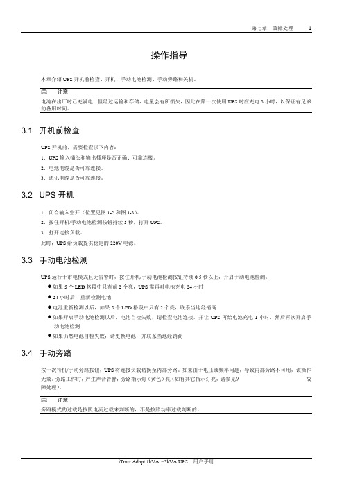
操作指导本章介绍UPS开机前检查、开机、手动电池检测、手动旁路和关机。
注意电池在出厂时已充满电,但经过运输和存储,电量会有所损失,因此在第一次使用UPS时应充电3小时,以保证有足够的备用时间。
3.1 开机前检查UPS开机前,需要检查以下内容:1.UPS输入插头和输出插座是否正确、可靠连接。
2.电池电缆是否可靠连接。
3.通讯电缆是否可靠连接。
3.2 UPS开机1.闭合输入空开(位置见图1-2和图1-3)。
2.按住开机/手动电池检测按钮持续3秒,打开UPS。
3.打开连接负载。
此时,UPS给负载提供稳定的220V电源。
3.3 手动电池检测UPS运行于市电模式且无告警时,按住开机/手动电池检测按钮持续0.5秒以上,开启手动电池检测。
●如果5个LED格段中只有前2个亮,UPS需再对电池充电24小时●24小时后,重新检测电池●电池重新检测以后,如果5个LED格段中只有2个亮,联系当地经销商●如果开启手动电池检测以后,电池自检失败,请检查电池连接,并让UPS再给电池充电1小时,然后再次开启手动电池检测●如果仍然电池自检失败,请更换电池,并联系当地经销商3.4 手动旁路按一次待机/手动旁路按钮,UPS将连接负载切换至内部旁路。
如果由于电压或频率问题,导致内部旁路不可用,该操作无效。
旁路工作时,产生声音告警,旁路指示灯(黄色)亮(如有其它指示灯亮,请参见0 故障处理)。
注意旁路模式的过载是按照电流过载来判断的,不是按照功率过载判断的。
故障处理本章介绍用户可能碰到的各种UPS症状以及在UPS故障时如何进行故障处理。
使用以下信息判断是否外部原因导致问题以及如何进行补救。
3.5 UPS症状以下症状表示UPS发生故障。
1.相关指示灯亮,UPS检测到故障。
2.产生声音告警,提示用户UPS需要检查。
3.5.1 指示灯除故障指示灯亮,一个或多个电池等级指示灯的LED格段可能同亮,给用户提供诊断帮助,如图7-1所示。
指示灯描述见表7-1。
- 1、下载文档前请自行甄别文档内容的完整性,平台不提供额外的编辑、内容补充、找答案等附加服务。
- 2、"仅部分预览"的文档,不可在线预览部分如存在完整性等问题,可反馈申请退款(可完整预览的文档不适用该条件!)。
- 3、如文档侵犯您的权益,请联系客服反馈,我们会尽快为您处理(人工客服工作时间:9:00-18:30)。
操作步骤 1操作步骤1 简介本章描述操作人员在各种运行模式下的各种操作步骤,包括UPS开机步骤,将负载切换到旁路的操作步骤和UPS关机步骤。
注1:操作步骤中所涉及的所有用户操作键和LED显示参见第八章操作控制显示面板。
注2:所有安装在UPS机柜内,打开机柜前门(带锁)可见到的电源开关参见第五章安装图。
2 开机步骤(进入逆变供电模式)此步骤用于在UPS完全下电的情况下进行开机,即在此之前UPS未对负载供电或通过维修旁路开关给负载供电。
这里假设UPS安装完毕,并已经由工程师调试正常,且外部电源开关已闭合。
对于并机系统,应对每台单机操作完一个步骤后,再进行下一个步骤的操作。
1.打开UPS门,可见电源操作开关。
2.闭合旁路输入开关Q2 和UPS输出开关Q5,并闭合所有外部输出隔离开关(如有)。
此时,LCD显示开始运行。
UPS启动后,UPS首先工作于旁路供电状态。
此时,旁路指示灯和负载指示灯亮。
LED指示灯状态如下表(参见图58):3.闭合整流输入开关Q1。
整流器启动时,整流器指示灯呈绿色闪烁。
约30秒后,整流器开始正常运行,整流器指示灯转绿色常亮。
4.闭合外部电池开关QF1(仅适用于带外置电池的UPS)。
该开关位于电池柜(如使用电池柜)内或电池架(如使用电池架)附近。
5.系统检测到电池的存在,电池充电器开始运行后,红色电池指示灯灭。
6.断开(或确认断开)内部手动旁路开关Q3,并断开外部维修旁路开关(如有)。
7.持续按INVERTER ON (逆变启动)开关2秒钟。
逆变器启动,当逆变器与旁路电压频率同步时,逆变器指示灯闪烁。
逆变器启动后,UPS从旁路供电切换到逆变器供电。
此时,旁路指示灯灭,逆变指示灯绿色常亮。
操作步骤 2 8.检查确认LCD显示屏右上角无任何告警信息,且LED显示状态如下:3 开机步骤(进入经济模式)仅适用于调试工程师已设置经济模式的单机系统。
完成7.2节所述操作步骤后,确认面板旁路指示灯呈绿色常亮(表明负载由旁路市电供电)。
4 电池测试模式操作步骤执行电池测试会将UPS切换至联合供电模式,由电池提供15%的负载供电,负载供电不足部分由交流输入市电提供。
有两种电池测试可选:维护测试–确认电池状态,使电池进行20%放电。
电池容量测试–精确检测电池容量,对电池进行完全放电(直至产生电池电压低告警)。
电池测试通过菜单进行操作,需通过密码认证。
如遇电池或市电故障,电池测试立即自动终止,UPS切换至其它电源给负载供电,负载供电不中断。
满足以下条件时,操作人员可通过控制面板启动电池测试:负载必须在UPS额定容量的20%~100%范围内。
电池必须刚完成5个小时以上浮充充电过程。
4.1 测试步骤1.在UPS前面板LCD上选择测试命令窗口。
使用左键或右键进入测试命令窗口。
2.选择所需测试。
使用切换窗口键(F1)和上/下键(F2,F3)将光标移至所需测试选项,按确认键(F4)确认。
屏幕提示后,使用上键(F2)用右键(F3)输入口令。
按确认键(F4)确认。
3.等待电池测试完毕。
测试完毕,系统自动更新计算所需后备时间(市电故障时显示)的电池数据和电池实际容量(相对新电池而言的电池容量百分比,逆变供电模式时显示)。
4.停止电池测试。
电池测试时,可通过选择测试命令窗口中的终止测试选项终止电池测试。
关于UPS控制面板操作的详细说明,参见第八章操作控制显示面板。
操作步骤 3 5 UPS自检操作步骤UPS自检功能可检查UPS的控制功能、面板LED摸拟指示和声音告警。
UPS自检通过菜单进行操作,需通过密码认证。
UPS自检过程需时5秒,可由操作人员通过控制面板启动。
5.1 UPS自检步骤1.在UPS前面板LCD上选择测试命令窗口。
使用左键或右键进入测试命令窗口。
2.选择所需测试。
使用切换窗口键(F1)和上/下键(F2,F3)将光标移至所需测试选项,按确认键(F4)确认。
屏幕提示后,使用上键(F2)用右键(F3)输入口令。
按确认键(F4)确认。
3.待电池测试完毕。
5秒后,屏幕提出测自检结果:整流器、逆变器、显示单元正常或故障。
4.停止电池测试。
电池测试时,可通过选择测试命令窗口中的终止测试选项终止电池测试。
关于UPS控制面板操作的详细说明,参见第八章操作控制显示面板。
6 维修旁路操作步骤(UPS关机步骤)以下操作步骤将负载从受UPS供电保护状态切换到通过维修旁路开关直接与交流输入旁路电源相连接的状态。
该开关位于:- UPS内部,即Q3-机柜前门后(单机系统或“1+1”冗余系统)。
-UPS外部,旁路柜内(“1+1”容量并机系统和“1+N”冗余并机系统,参见图56)。
对于并机系统,应对每台单机操作完一个步骤后,再进行下一个步骤的操作。
1.按UPS前面板上的INVERTER OFF按钮,UPS逆变器关闭,UPS通过静态旁路给负载供电。
此时,逆变器指示灯(4)灭,总告警指示灯(6)亮。
2.对于单机系统和“1+1”冗余并机系统,闭合内部维修旁路开关Q3和任何外部维修旁路开关(如有)。
3.对于“1+N”冗余并机系统和“1+1”容量并机系统,闭合外部维修开关。
4.此时维修旁路电源与UPS静态开关电源并联。
5.显示窗会显示所执行的相关操作,即维修旁路闭合等。
6.开输出开关Q5。
此时,已完成UPS到维修旁路的切换操作,负载直接由维修旁路供电。
如需关闭整流器和电池,请继续执行以下操作步骤。
7.按下相应UPS单机的前面板上的紧急停机(EPO)按钮。
该操作将关闭整流器和逆变器,断开静态开关和电池,但不影响手动维修旁路开关。
操作步骤 2操作步骤 5 7 关机步骤(完全关闭UPS和负载)UPS完全关机及使负载断电时应遵循此步骤。
所有电源开关及断路器均断开,UPS不再给负载供电。
对于并机系统,应对每台单机操作完一个步骤后,再进行下一个步骤的操作。
1.按UPS前面板上的紧急停机(EPO)按钮。
此操作将关闭整流器和逆变器,断开静态开关和电池,使负载断电。
注:除非紧急情况,否则请勿按远程紧急开关(EPO)按钮。
2.打开UPS门,可见电源操作开关。
3.断开整流器输入开关Q1。
4.断开外部电池开关QF1(如有外置电池)。
该开关位于电池柜内(如使用电池柜)或电池架附近(如使用电池架)。
5.断开输出开关Q5。
6.断开旁路输入开关Q2。
7.确认维修旁路开关Q3断开。
8.随着所有信赖市电供电的内部电源关闭,面板上的所有LED指示灯灭,LCD显示闭闭。
9.为使UPS完全断电,必须断开其外部市电配电开关(对于整流器和旁路使用独立电源输入的分离旁路系统,则有两个开关)和外部输出开关,并贴上警告标志。
8 紧急停机(EPO)步骤紧急停机(EPO)开关用于在紧急情况下(如火灾,水灾等)关闭UPS。
系统将关闭整流器、逆变器,并迅速切断负载供电(包括逆变和旁路输出),且电池停止充电或放电。
如UPS仍有市电输入,则UPS控制电路仍带电,但UPS输出已关闭。
如需彻底切换UPS的市电电源, 应断开UPS的外部市电输入开关。
9 紧急停机(EPO)或其它情况导致关机后的UPS复位步骤当使用了EPO(紧急停机)或逆变器过温、过载关机、电池过压、切换次数过多(BYP:XFER COUNT BLOCK)等原因导致UPS关机后,根据显示屏上提示的告警信息采取措施清除故障后,使用以下UPS复位步骤使UPS恢复正常工作状态。
用户确认故障已清除并无远程EPO信号后,执行以下步骤:1.按FAULT CLEAR键使系统退出紧急关机状态。
2.按住操作控制面板右侧的INVERTER ON键超过2s。
操作步骤 2按下EPO按钮后,如已切断UPS的市电输入,UPS完全关机。
当市电输入恢复时,如旁路输入电源开关(Q2)和UPS 输出电源开关(Q5)闭合,UPS将启动并进入旁路模式运行,恢复输出。
按下EPO按钮后,如已切断UPS的市电输入,UPS完全关机。
当市电输入恢复时,如旋转开关(SW1)位于BYPASS 或NORMAL位置,UPS将启动并进入旁路模式运行,恢复输出。
10 自动启动市电停电时,UPS通过电池系统给负载供电,直至电池放电至电池放电终止电压(EOD),UPS停止输出。
满足以下条件后,UPS将自动重新启动,恢复输出供电。
●市电恢复后●UPS已设置自动启动功能●经自动启动延时后(缺省设置为10分种)。
自动启动延时过程中,UPS给电池充电,以防止市电再次停电给负载设备带来断电危险如UPS未设置自动启动功能,用户可通过按Fault Clear键手动启动UPS。
11 选择语言LCD菜单和数据可以12种语言显示,包括汉语、荷兰语、英语、法语、德语、意大利语、日语、波兰语、葡萄牙语、俄语、西班牙语、瑞典语。
执行以下步骤选择所需语言。
1.在主菜单下,按F1(切换窗口)键将光标移至屏幕首行菜单。
2.按F2和F3(左移和右移)键选择语言(Language)菜单。
3.按F1(切换窗口)键将光标移至屏幕的UPS数据窗口。
4.使用F2和F3(上翻和下翻)键选择所需语言。
5.按F4(确认)键确认。
6.重复按F1(ESC)键回到主菜单。
此时,LCD中所有文字将以所选语言显示。
12 更改当前日期和时间如需更改系统日期和时间,执行以下步骤:1.在主菜单下,按F1(切换窗口)键将光标移至屏幕首行菜单。
2.按F2和F3(左移和右移)键选择功能设置菜单。
3.按F1(切换窗口)键将光标移至屏幕的UPS数据窗口。
4.使用F2和F3(上翻和下翻)键选择日期时间设置选项,然后按F4(确认)。
5.将光标移至日期和时间显示行,按F4 (确认)。
6.使用F2和F3(上翻和下翻)键输入当前日期和时间。
操作步骤7 7.按F4(确认)确认,按F1(退出)回到主菜单。
13 控制口令系统提供口令保护,对操作人员的某些控制操作进行限制。
缺省密码为“12345”。
只能通过密码确认后才可执行UPS 和电池测试操作。
操作控制显示面板16操作控制显示面板1 简介UPS的操作显示面板位于前面板上。
通过操作显示面板,可对UPS进行操作控制,和查询UPS的所有参数、UPS和电池状态、以及事件和告警信息。
操作显示面板按功能可分为三部分:摸拟电流图,LCD显示和菜单键,控制操作键。
摸拟电流图LCD显示和菜单键控制操作键图58 UPS操作控制显示面板表13 UPS操作控制显示面板部件描述1.1 摸拟电流图摸拟电流图上提供LED指示灯,显示了UPS的各种工作路径及UPS的当前工作状态。
表14 整流器指示灯(1)状态描述表15 电池指示灯(2)状态描述操作控制显示面板9表16 旁路指示灯(3)状态描述表17 逆变器指示灯(4)状态描述表18 负载指示灯(5)状态描述表19 状态(告警)指示灯(6)状态描述1.2 声音告警(蜂鸣器)UPS在运行过程中可伴随以下三种不同的声音告警:表20 蜂鸣器声音告警描述1.3 功能操作按钮(键)操作功能操作键时,需持续短暂地按下相应的键,直至听到蜂鸣器鸣叫方可松开。