MTL 5000系列安全栅样本说明
mtl安全栅组态中文说明书

mtl安全栅组态中文说明书
MTL安全栅组态中文安全说明书
1、隔离式安全栅应安装在非危险场所。
2、隔离式安全栅通往现场(危险场所)的软铜导线截面积必须大于0.5mm。
3、连接导线的绝缘强度大于500V。
4、隔离式安全栅本安端(有蓝色标记)和非本安端电路配线,不得接错和混淆。
本安导线宜选用蓝色作为本安标记。
本安导线和非本安导线在汇线槽中应分开铺设,采用各自保护套管。
5、隔离式安全栅与一次仪表组成本安安全防爆系统时,必须经国家指定的防爆检验机构检验认可。
6、对隔离式安全栅进行单独通电调试时,必须注意隔离式安全栅的型号、电源极性、电压等级及隔离式安全栅外壳接线端上的标号。
7、严禁用兆欧表测试隔离安全栅端子之间的绝缘性。
若要检查系统线路绝缘性时,应先断开全部隔离式安全栅接线,否则会引起内部器件损坏。
8、凡与隔离安全栅相连接的现场仪表,均应为有关防爆部门进行防爆试验并取得防爆合格证的仪表。
MTL5500系列安全栅修改配置-杨红14年04月

MTL5500系列安全栅修改配置以MTL5575为例加以简要说明(输入PT100、三线制,输出4~20mA,量程范围0~200℃):1、安装调试软件PCS45_Install_V3.11以及电缆驱动PCS45_USB_Driver2.08.14,电缆驱动需将电缆连接到电脑方可安装。
2、将电缆一端接电脑(USB),另一端接到MTL5575模块(圆头)上的CONFIG端口。
接通模块电源(DC24V,14为正端,13为负端),将模拟电阻器接到相应的端子(一端接到3,另一端引出两根线分别接到1和4);待模块上的指示灯PWR黄灯由闪烁变成常亮即可开始连线软件修改配置。
3、双击图标打开软件,输入密码“MTL”,显示“Password input ok.Allfunctions enabled密码输入ok。
所有功能启用”。
4、菜单“Options选项”-“Port selection端口选择”进行端口设置,如下图:点击“Accept接受”即可。
5、菜单“File文件”-“New新建”-“Select device选择设备”,勾选“MTL4575”,点击“Accept接受”。
6、菜单“Connection连接”-“Establish建立”,跳出对话框“Confirm确认”:“There is device data in the memory.Should the data be overwriten?有设备内存中的数据。
数据应该写入吗?”,点击“OK”连接模块与软件;跳出画面“Establish建立”:“Data exchanging.Please wait…数据交换。
请稍等…”,如下图:7、菜单“Device data设备数据”-“Input config.输入配置”-“Configure inputdata配置输入数据”,在“RTD types RTD类型”处勾选“Pt100”,在“wiring”处勾选“3-wire”,其余的为默认;单击“Accept接受”,待修改完毕点击“Close”关闭窗口,输入数据即配置完毕。
MTL安全栅的技术说明

MTL安全栅的技术说明MTL是世界著名本安仪表品牌,本安技术多年居领先地位,MTL仪器仪表(中国)有限公司(以下简称MTL)是MTL公司全球业务的一部分,多年来在中国所有的大型石化企业的装置大量应用,占主装置进口安全栅份额的70%以上。
尤其在近几年百万吨乙烯和千万吨炼油项目中90%均采用MTL安全栅,如兰州乙烯,茂名乙烯,赛科100万吨乙烯,福建100万吨乙烯一体化(含1000万吨炼油),海南1000万吨大炼油,青岛1000万吨大炼油,燕山石化1000万吨炼油改造,广石化800万吨炼油,武石化800万吨炼油。
在这些大项目中,均采用DCS与安全栅整体采购,这样可以减少工作界面与中间环节,便于项目管理,提高工程效率,这种模式也是国际上正在流行的采购模式,说明中国的工程建设当正在引入先进的国际化工程理念。
在本项目中MTL可以提供成熟的、有丰富应用经验的底板安装方案,这是一种世界上最先进的接线和安装方式,优点在于:1.减少接线环节,减少故障点,提高系统可靠性。
2.节省机柜空间,减少机柜数量,利于控制室排布。
3.集成非常快捷,缩短开车调试周期。
4.便于系统运转后的日常维护和管理。
5.底板安装支持各家DCS厂商:Yokogawa, Honeywell, ABB, Foxboro, Triconex, Siemens,August Systems 。
6.已经取得IEC的SIL2认证,技术上亦可实现SIL3的安全标准。
为了更好地为中国的用户服务,MTL在上海和北京都配有丰富工程经验的高级应用工程师。
MTL引以自豪的是我们的生产效率和产品质量,但我们清醒地认识到在高速发展的工业领域,我们必须不断改进产品结构和提高质量,使MTL永远站在本质安全领域的前列,才能更好地服务用户。
P+F安全栅在国内使用故障的装置:1.2004年上海氯碱厂离子膜烧碱装置中P+F的温度变送器隔离栅使用时多次出现故障,更换过两次,给生产造成很大的影响。
MTL安全栅
品牌:MTLMTL是一家英国知名公司,成立于25年前,它的本质安全栅和隔离栅成为工业标准已有多年。
该公司在工业过程控制,特别是本安领域中一直处于国际领先地位。
MTL产品在质量、可靠性和安全性方面已经成为工业标准,并获得世界上许多权威机构的认证.MTL公司主要生产齐纳栅、隔离栅、多路转换器、显示器和过程I/O,并同DCS公司和系统集成商有紧密的合作,为石油、石化等工厂提供防爆产品。
MTL公司同时也生产防雷击抗浪涌保护器。
在中国,MTL产品已广泛应用于化工及石油化工、水处理、冶金、制药、电力、水泥、纸浆和造纸、公用事业自动化等领域。
MTL700系列实际是一种“工业规格”,产品注意了固定安装和接地排列。
其运用范围包括超电压保护和子系统电源超高保护。
单通道和双通道供用户任意选择MTL702+/705+/706+/707+/707P+/708+/710+/710-/710ACMTL710P+/710P-/715+/715-/715P+/722+/722-/722P+MTL728+/728-/728AC/728P+/729P+/751AC/755AC 等MTL4000系列第三代隔离接口单元为本安电路集成在大/中型过程控制系统装置提供了一个新的思路。
由于该系列产品结构特别小巧。
因此,具有安装密度高的特点,每个组件是借助于由多通路连接器制成的安全区连接件插件在系统地板上的,这是一种既可简化工程又可降低安装维修费用的方法MTL4013/4014/4015/4016/4017/4021/4023/4024/4025MTL4031/4032/4041/4042/4043/4044/4045/4046/4047MTL4053/4061/4073/4081/4215/4216/4220 等MTL5000系列是MTL最新推出的本安隔离栅,使系统布置和安装更为简便,5000系列提供所有通用功能,因此,安装设计简单易行。
MTL5000系列夹紧式安装方法可将其快速装于DIN导轨上,完全是一种工业标准安装系统,安全区和危险区接线采用简单的插入式接线块,电源插头有多种形式,因此,接线快速,减少接线错误,安全使用,排列整齐。
MTL隔离栅

1 1 1 1 2 2 2 1 2
1 1 2 2 1 2 2
1CH SMART TX REPEATER 4-20MA 1CH SMART REP 4-20MA PASSIVE INPUT 1CH SMART TX REP 4-20MA SINK 1CH REP 4-20MA PASSIVE I/P SINK 2CH SMART TX REPEATER 4-20MA 2CH SMART REP 4-20MA PASSIVE INPUT 2CH REP 4-20MA PASSIVE I/P SINK DUAL O/P SMART TX REPEATER 2CH SMART TX REP 4-20MA SINK
New 5500 Series
新技术的应用
MTL4500/5500新型隔离栅采用:
新的变压器技术 – 使得功耗大大降低,便于集成
最新的技术使得产品具有低功耗和高精度
产品的连续性
MTL5000 系列隔离栅 以安装简单、性能可靠 而闻名” 产品的兼容性: • 支持现有的装置 • MTL4500 可以安装在现有的底板 上
AO模拟量输出 温度隔离栅
MTL4546Y/MTL4549Y MTL4575 MTL4576-THC/RTD
MTL4532 MTL4531/MTL4533
MTL5546Y/MTL5549Y MTL5575 MTL5Байду номын сангаас76-THC/RTD
MTL5532 MTL5531/MTL5533
PI 脉冲隔离栅 振动位移隔离栅
双通道的温度变送器
可以连接各种现场温度信号
•2/3线制热电阻 Pt100/Pt500/Pt1000/Cu-50/Cu53 Ni100/500/100
MTL安全栅

配Siemens的一体化底板 CPM16-SM331AI(R)
主要特点
配Siemens的一体化底板 CPM16SM332AO(R)
5、配Tricon的一体化底板
MTL4500 隔离安全 栅
冗余电源
冗余电源 报警输出
HART信 号电缆接 口
Triconex IO 卡件接口
6、配HIMA的一体化底板
主要特点
13.符合FSM认证标准(MTL FSM), MTL是过程仪表设备供 应商中第一家取得该认证的厂家。对于安全完整性等级(SIL)认 证是对整个回路的考虑而不只是某个部件,而对于具体的部件 ,不同的计算方式得出的SIL等级也不同,通常需要提供基本数 据而不是SIL等级给ESD厂家计算整个回路的等级。(SIL)
安全栅类型
开关量输出:
MTL4521/L loop powered solenoid driver MTL4523 solenoid driver with LFD MTL4523R solenoid driver with LFD MTL4523L loop powered solenoid driver + LFD MTL4524 switch operated solenoid driver MTL4524S switch operated solenoid driver, 24V override MTL4525 switch operated solenoid driver MTL4526 2ch switch operated relay
(MTL3052除外)
1992年投放市 场 2010年停产
1995年投放市 场
MTL新一代隔离式安全栅
MTL4500系列 2007年投放市场,是 MTL新一代底板式安装 的隔离式安全栅
MTL安全栅组态下装及校验指导书-雷进莹
MTL安全栅组态下装及校验指导书编写人雷进莹审核人批准人受控状态2009 年月日发布 2009 年月日实施洛阳三隆安装检修有限公司1 本作业指导书适用范围适用于MTL厂家中需要组态的安全栅的组态下装及校验,主要针对安全栅中的温度变送器,即温度转变成4-20MA。
2 本作业的目的为规范正确的MTL安全栅组态校验的步骤,保证作业过程的安全3 人员资格、人员数量及职责分工3.1操作人须持有三隆公司发给的《安全技术操作合格证》。
操作人须具有一年以上现场仪表施工维护工作经验。
要求作业人员2人,1人作业1人监护。
3.2职责分工3.2.1车间技术组是本作业指导书的主管部门,负责对作业的技术指导、监督、检查。
3.2.2各班组在作业过程中应严格执行操作技术要求及相应安全生产禁令。
4 工器具准备及要求4.1仪表工具2套、笔记本一台、MTL通讯适配器一个,万用表一台。
4.2笔记本内已经安装了MTL安全栅组态程序和适配器驱动程序。
5 着装要求:需正确佩戴安全帽、防护眼镜、劳保着装。
6 作业前检查项目6.1检查接线是否正确。
6.2检查安全栅电源是否正常。
7 技术要求和技术要点7.1在修改下装过程中必须断开连接之后,才能拔下适配器。
7.2所有的密码都是MTL。
8 作业方法和步骤8.1联系工艺规范填写<三隆公司仪表专业日常作业许可证>。
8.2将此安全栅对应的仪表投至手动或校验位。
8.3连接编程器8.3.1将笔记本打开,并把适配器与笔记本连好。
8.3.2将适配器的另外一端与安全栅连接。
8.4安装程序(如果已经安装忽略此步骤)8.4.1 打开光盘,安装组态程序PCS45,比如Pcs45V2p03.exe;8.4.2把适配器与笔记本U口相连,安装驱动程序,此程序在Driver文件夹下;8.5组态8.5.1打开程序“PCS45 Configuration software”。
8.5.2点击connection→establish,与安全栅连接上。
MTL5500系列安全栅说明书
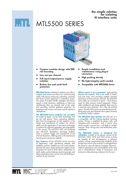
Where space is at a premium, high packing densities are essential. With a unit width of 16mm, and with many units providing multiple channels (and hence a lower cost per channel), the MTL5500 Series takes up a minimum of space – which leaves more for other process control equipment. Where older installations are being updated, there may be a need for more channels – but within the existing space. The MTL5500 Series can provide the answer, fitting extra units and channels into a space formerly occupied by bulkier isolators.
TM5000安全栅
的直流信号。 ● 模块化表芯设计,内部采用数字化调校,无需零点
和满度调节电位器,温度漂移自动补偿。 ● 带有工作电源指示灯。 ● 单通道,一路输入一路输出,本安输入回路
[Exia]IIC,输入回路短路保护。 ● 即插即拔式接线端子,DIN 导轨卡式安装。
描述
TM 5041 现场电源信号输入隔离式安全栅,是向现场 危险区域的变送器提供隔离的电源电压,并将变送器产 生的 4~20mA 信号经本隔离式安全栅转换成所需的 直流信号至安全区控制系统或其它智能仪表。
重庆宇通仪器仪表有限公司
CHONGQING YUTONG INSTRUMENT CO.,L
TM 系列隔离式安全栅
目录 模拟量输入(2/3 线制变送器 4~20mA) TM 5041 现场电源配电信号输入隔离式安全栅(一入一出)...............................................1 TM 5043 现场电源配电信号输入隔离式安全栅(一入二出)...............................................3 TM 5044 现场电源配电信号输入隔离式安全栅(二入二出)...............................................5 TM 5900 现场电源配电信号输入(HART)隔离式安全栅(一入一出)..................................7
MTL安全栅

Dummy isolator general purpose feed-through module
MTL4510开关量输入
1、四通道
2、危险区信号:开关/接近开关 3、安全区信号:固态继电器 4、输出电压:7 – 9VDC 5、安全区和危险区之间隔离
电压为250V AC
6、供电:20-35V DC
11.能适应较宽的温度范围:-20 – 60 度,湿度范围:
0 - 95%,供电范围:20 – 35V DC。
12.电磁兼容性符合EMC EN650 081-2/EN050 682-2标准。
主要特点
13.符合FSM认证标准(MTL FSM), MTL是过程仪表设备供应商 中第一家取得该认证的厂家。对于安全完整性等级(SIL)认证 是对整个回路的考虑而不只是某个部件,而对于具体的部件, 不同的计算方式得出的SIL等级也不同,通常需要提供基本数 据而不是SIL等级给ESD厂家计算整个回路的等级。(SIL) 14.采用小巧积木化设计结构 并带有插接式连接端子,安全 区信号直接与底板连接,无需 外部接线。提供两个冗余电源 接口,确保供电可靠。
Haz area (Field) Safe area (System)
Power supply
干扰能力强。 2.采用集成电路和表面
封装技术,保证了安全 栅的精度。
主要特点
3.采用新型变压隔离技术,优化的设计,新型电子元器件,使安 全栅功耗更低,可靠性更高。 例如:MTL4500/5500与MTL5000功耗比较: MTL5000 MTL4500/5500
温度输入: MTL4575 MTL4576-THC MTL4576-RTD MTL4581
其它: MTL4599 MTL4599N
MTL安全栅_

传统点对 点方案
一体化 方案
MTL5500
DCS
Multicore cable
MTL4500
DCS
主要特点
1、配Honeywell C300的一体化底板
Series C300
Safety Manager
2、配FOXBORO I/A系统一体化底板
3、配Yokogawa CS3000 DCS的一体化底板
MTL新一代隔离式安全栅
MTL4500 Series
MTL5500 Series
通用的PCB电路板
MTL新一代隔离式安全栅
通用的外壳 可选择的标准部件
MTL4500
MTL5500
2、MTL4500系列 隔离栅
MTL4500隔离式安全栅
主要特点
1.输入/输出/电源三端
Haz area
隔离,隔离性能高, 抗 (Field) 干扰能力强。
主要特点
17. 安全栅和底板密集设计,减轻了重量,提高了安装密度。 安全栅厚度仅16mm,底板有4、8、16、24个组件等多种选 择。
客户化解决方案
主要特点
MTL5541
MTL5541MTL安全栅MTL700系列:MTL700系列安全栅实际上已经成为一种工业标准,以具有***,接地可靠,现场验证回路等特点而著称。
这个系列还包括有过压保护型和高功率型安全栅。
单通路和双通路组件的厚度相同。
NORTHSTARMTL安全栅MTL4700系列:MTL4700系列采用MTL700系列的设计回路,底板安装方式,与MTL700系列隔离栅类似,多通路设计(一个模块***多6个回路),达到高集成性,可定制的底板允许与过程控制系统和承包商机柜密集整体使用。
倍加福编码器,MTL安全栅MTL7000系列:MTL7000系列基于采用MTL700系列的设计回路,这些超薄性安全栅具有并可替代传统接线端子的众多功能,节省了一半的端子。
单通路,双通路,三通路组件仅7mm厚,直接在DIN标准导轨上完成安装接地。
可选的可更换熔断器几脱卸式短接线起到断路器的作用—快速、简单、密集安装,真正的安全自检安装和维护。
MTL安全栅MTL4000系列:MTL4000系列:1、安装在系统底板和***底板上;2、24V直流总线电源向底板供电;3、紧密模块化设计,带插接式;4、高度集成,16mm宽;5、应用***;6、降低系统工程安装费用;MTL安全栅MTL5000系列:MTL5000系列:1、高度集成,16mm宽;2、24VDC供电;3、每一通路费用低,大部分是双通路;4、DIN导轨安装;5、安装简单,带插接式连接件。
MTL5011B MTL5511MTL5012 MTL5513MTL5014 MTL5514MTL5015 MTL5513MTL5018 已停产 MTL5516CMTL5022 MTL5522MTL5023 MTL5523MTL5024 MTL5524MTL5025 已停产 MTL5525MTL5041use已停产MTL5541MTL5043 已停产 useMTL5544替代MTL5044 已停产 MTL5544替代MTL5044D 已停产useMTL5544替代MTK5045 已停产 use MTL5546替代MTL5046 已停产 MTL5546替代MTL5049 已停产 MTL5549替代MTL5073 已停产MTL5575替代MTL5074 已停产 MTL5575替代MTL5099 已停产 MTL5599替代。
MTL安全栅技术交流解析

0.1 最小点燃能量 MIE
可燃范围
0.01 0 10 20 30 40 50 体积浓度 % 60 70 80 90 100
Introduction
爆炸下限 LEL
UEL 爆炸上限
火花点燃特性
A10
可燃性气体/空气混合物的整个可点燃的浓度范围称为
“可燃范围”
物质 丙烷 乙烯 爆炸下限LEL 爆炸上限UEL 最小点燃能量 uJ 2% 2.7% 9.5% 34% 180uJ 60uJ 点燃特性 难
II组设备分类:
1类:用于Zone 0和Zone20; 在正常工作、一个故障和二 个单独的计数故障时均不能点燃爆炸性混合物的设备。
2类:用于Zone 1和Zone21; 在正常工作、一个故障时均 不能点燃爆炸性混合物的设备。
3类:用于Zone 2和Zone22; 在正常工作时不能点燃爆炸 性混合物的设备。
CENELEC: 欧洲电工技术委员会
BASEEFA: 英国防爆检验机构 FM: 美国工厂联合会 UL: 美国保险商实验室 NEC: 美国国家电气规范 NEMA: 美国电气制造商协会 CSA: 加拿大防爆检验机构 PTB: 德国防爆检验机构
Introduction
防爆认证机构
A27
第一位特征数字
防止固体异体异物进入
氢气
4%
76%
20uJ
易
Introduction
可燃物质的爆炸极限
A11
在中国和IEC国家, 爆炸性物质分为三类:
I 类: 矿井甲烷
II 类: 爆炸性气体混合物(含蒸气、薄雾)
III 类: 爆炸性粉尘和纤维
在北美(美国及加拿大),爆炸性物质分为三类(称为Class)
MTL 过压保护设备说明书

MTL TP rangeTransmitter mounting surge protector1Eaton Electric Limited,Great Marlings, Butterfield, LutonBeds, LU2 8DL, UK.Tel: + 44 (0)1582 723633 Fax: + 44 (0)1582 422283 E-mail:********************© 2022 EatonAll Rights ReservedPublication No. INS 801-640 Rev EMarch 2022IntroductionThe TP range of surge protectors provides surge protection for field mounted process transmitters and is available for 1/2’’NPT, 20mm ISO and G1/2” threaded conduit entries. The TP range is certified and approved for use in hazardous areas. More details of this are shown throughout this installation guide.Important safety informationInstallationSelect conduit entry to be used for installation, and remove any blanking plug.NOTEIf direct installation onto the apparatus itself is impossible e.g. because all conduit entries are in use already, an external junction box or conduit hub can be used. The TP range is supplied with 300mm leads, which should be sufficient for them to reach the transmitter terminals from a junction box. If these leads are not long enough then use supplementary terminals and wiring. Installation should be within 1m of, and bonded to, thetransmitter.Ensure that the TP body thread matches the conduit entry. Thread types are not interchangeable, but adapters may be used where necessary. For explosionproof (Ex d) installations, only certified or approved adapters are permitted.Remove apparatus terminal housing cover.Insert connecting wires into apparatus body and start threading unit into conduit entry using moderate hand-force, with lubricants as necessary.Tighten fully (hand-tight plus 1/2 turn of 23mm A/F spanner). The steel body of the TP48 is not used as part of the electrical circuit, therefore sealing of the thread with PTFE tape or other sealing compounds will not affect the performance of the TP48.For effective protection, the leads of the TP should be as short as possible. Before wiring to the transmitter terminals, cut the leads to the appropriate length and strip back 10mm of insulation.Do not try to coil excess lengths of cable into the transmitter housing as this will degrade the protection given by the surge protector.Connect the flying leads to the terminals as indicated in Figure 1.2INS 801-640 Rev E3INS 801-640 Rev ENOTEThe protection circuit needs to be connected in parallel with the transmitter 4-20mA current loop, not in series. Many transmitters offer linked terminals to avoid installation with multiple wires in each terminal. If your transmitter does not, then use an appropriate termination method e.g. ring-tag, piggy-back Fastontab, split ferrule etc. to complete the connection satisfactorily.Ensure that all connections are tight, particularly the earth bonding connection, which is likely to be via a stud within the apparatus terminal housing. Refit apparatus terminal housing cover.Reconnect circuit if it was previously isolated.TP32-T only: The TP32-T is a FISCO/Fieldbus terminator. It can be used as a spur terminator and surge protective device. Make sure no other terminating blocks are in use for the spur.Earthing / groundingThe TP earth wire (Green/Yellow) should be connected to the earth terminal or stud usually provided inside the transmitter housing. In the unlikely event that no such stud exists, make the connection to a structural mounting part, such as a terminal block fixing screw.MaintenanceAt intervals of not more than one year (more frequently for particularly harsh environments) visually check the installation and ensure that: i) Device and/or enclosure is firmly attached to mounting ii) There are no signs of external damage or corrosioniii) Interconnecting cables are not frayed or otherwise damagediv) All connections are properly made with clear labellingIf this unit suffers damage send back to Eaton for evaluation which should only be carried out by MTL product line. This product is not field repairable.ApprovalsIn hazardous locations check the marking on the device to ensure that it is appropriate for the application. Mark either the top group of three check boxes to indicate Ex ia use, or the bottom group of two to indicate Ex d use. For marking use a punch mark.Special conditions for Safe Use:Ex ia protection concept (IECEx BAS 07.0045X, Baseefa04ATEX0251X, BAS21UKEX0560X)1. The apparatus is to be installed such that the flying leads are afforded a degree of protection of at least IP54.2. Although all the TP**-*-* Series Surge Protection Devices covered by this certificate will meet the 500V test to the metal case, the electrical circuits within the Series Surge Protection Devices are not capable of withstanding the 500V test to the Green/Y ellow wire for one minute without breakdown. This must be taken into consideration in any installation.3. These devices are not provided with an external connection facility for an earthing or bonding conductor. Adequate earth continuity via the mounting arrangement must be ensured.For entity parameters see certificates shown below.Figure 2 IECEx certification detailsEaton Electric Limited,Great Marlings, Butterfield, Luton Beds, LU2 8DL, UK.Tel: + 44 (0)1582 723633 Fax: + 44 (0)1582 422283E-mail:********************© 2022 EatonAll Rights ReservedPublication No. INS 801-640 Rev E 160322March 2022EUROPE (EMEA): +44 (0)1582 723633 ********************THE AMERICAS: +1 800 835 7075 *********************ASIA-PACIFIC: +65 6 645 9888***********************The given data is only intended as a productdescription and should not be regarded as a legal warranty of properties or guarantee. In the interest of further technical developments, we reserve the right to make design changes.44. This apparatus is also afforded Flameproof Certification to Baseefa04ATEX0053X, IECEx BAS 15.0056X BAS21UKEX0559X and is dual marked. On installation the relevant protection concept must be permanently marked on the apparatus in the space provided.Ex db protection concept (IECEx BAS 15.0056X, Baseefa04ATEX0053X, BAS21UKEX0559X)1. The permanently attached cables shall be suitably protected against pulling, mechanical damage and terminated within a terminal or junction facility suitable for the conditions of use.2. These devices are not provided with an external connection facility for an earthing or bonding conductor. It is the user’s responsibility to ensure adequate earth continuity via the mounting arrangements.3 . This equipment is also afforded Intrinsically Safe Certification to Baseefa04ATEX0251X, IECEx BAS 07.0045X and BAS21UKEX0560X and hence the equipment is dual marked. It is the user’s responsibility to determine the protection concept to be applied and permanently mark the equipment in the space provided for guidance in installation and maintenance.4. If attached to a flameproof enclosure the surge protectors shall be provided with a high strength locking compound on the mounting thread.For U.S./CAN installations, the TP Surge Protectors are Approved for Class I, Zone 0 applications. If connectingAEx [ib]/Ex [ib] Associated Apparatus or AEx ib/Ex ib I.S. Apparatus to the TP Surge Protectors the I.S. circuit is only suitable for Class I, Zone 1, or Class I, Zone 2,vices with entity parameters not specifically examined in combination as a system when: V oc or U o or V t < Vmax, I sc or I o or I t < I max , C a or C o , C i + C cable , L a or L o , L i + L cable , and for FM only: P o < P i .b) Dust-tight conduit seal must be used when installed in Class II and Class III environments.c) Control equipment connected to the Associated Apparatus must not use or generate more than 250Vrms or Vdc.d) Installation in the U.S./CAN should be in accordance with ANSI/ISA RP12.6 “Installation of Intrinsically Safe Systemsfor Hazardous (Classified) Locations” and the National Electrical Code® (ANSI/NFPA 70) Sections 504 and 505, Canadian Electrical Code, CE code or CSA C22.1e) The configuration of associated Apparatus must be Factory Mutual Research Approved under Entity Concept.f) Associated Apparatus manufacturer’s installation drawing must be followed when installing this equipment.g) For U.S./CAN installations, the TP Surge Protectors is Approved for Class I, Zone 0 applications. If connect ing AEx [ib]/Ex [ib] Associated Apparatus or AEx ib/Ex ib I.S. Apparatus to the TP Surge Protectors the I.S. circuit is only suitable for Class I, Zone 1, or Class I, Zone 2, and is not suitable for Class I, Zone 0 or Class I, Division 1, Hazardous (Classified) Location.。
MTL安全栅介绍

介绍INA5500 MTL5500系列安全指令(ATEX)手册INM5500 MTL5500系列说明书手册MTL4500-5500-ACC 外壳及配件数据表MTL4500-5500-CS 常用规格数据表MTL4500-5500-DS MTL4500-5500系列数据集数据表2。
数字输入MTL5501-SR 1路DI故障安全固态输出+ LFD报警数据表MTL5510 4路DI固态输出中数据表MTL5510B 4路DI多功能固态输出数据表MTL5511 1路DI中继输出数据表MTL5513 双声道DI固态输出数据表MTL5514 1路DI继电器输出+ LFD报警数据表MTL5516C 转换继电器输出双声道DI 数据表MTL5517 双声道DI继电器输出+ LFD报警数据表3。
数字输出MTL5521 回路供电的电磁驱动,IIC 数据表MTL5522 回路供电的电磁驱动,IIB 数据表MTL5523 电磁驱动器LFD 数据表MTL5523V 驱动器与电压控制电磁阀/报警数据表MTL5524 开关操作的螺线管驱动器数据表MTL5525 回路供电的电磁驱动器的低功耗数据表MTL5526 双声道开关操作继电器数据表4。
模拟输入MTL5541 1路2/3线制变送器中继数据表MTL5541A 1路发射机直放站,无源输入数据表MTL5541AS 1路发射机直放站,无源输入,吸入电流数据表MTL5541S 1路2/3线制变送器中继器,吸入电流数据表MTL5544 2CH 2/3线制变送器中继器数据表MTL5544A 双声道发射中继器,被动输入数据表MTL5544AS 双声道发射中继器,被动输入,电流下沉数据表MTL5544D 1路2/3线制变送器中继器,双输出数据表MTL5544S 2CH 2/3线制变送器中继器,吸入电流数据表5。
模拟输出MTL5546 1路4-20mA的智能隔离驱动+ LFD 数据表MTL5546Y 1路4-20mA的智能隔离驱动+ OC LFD 数据表MTL5549 2CH 4-20mA的智能隔离驱动+ LFD 数据表MTL5549Y 2ch的4-20mA的智能隔离驱动+ OC LFD 数据表6。
- 1、下载文档前请自行甄别文档内容的完整性,平台不提供额外的编辑、内容补充、找答案等附加服务。
- 2、"仅部分预览"的文档,不可在线预览部分如存在完整性等问题,可反馈申请退款(可完整预览的文档不适用该条件!)。
- 3、如文档侵犯您的权益,请联系客服反馈,我们会尽快为您处理(人工客服工作时间:9:00-18:30)。
MTL5000 SERIESACCESSORIESMTL5000 Series isolators mount quickly and easily onto standard DINrail. A comprehensive range of accessories simplifies earthing andtagging arrangements.MOUNTING DETAILS16mm235mm222Type BType ATH5000 DIN-railSee also‘MTL5000 Series powerbus kits' MOUNTINGTHR2 DIN rail,1m lengthDIN rail to EN50022; BS5584; DIN46277MS010 DIN rail module spacer, 10mm, pack of 5Grey spacer, one required between each MTL5995 and anyadjacent module on a DIN rail, to provide 10mm air-circulationspace between modulesEARTH RAIL AND TAG STRIPIMB57 Insulating mounting blockOne required at each end of a tagging strip/earth rail. Suitable forlow-profile (7.5mm) and high-profile (15mm) symmetrical DIN rail.ETM7 Earth terminal, bag of 50For terminating cable screens and 0V returns on the ERL7 earth rail.For cables ≤4mm2. Exact dimension dependent on manufacturer.TAG57 Tagging strip, 1m lengthCut to size. Supplied with reversible tagging strip label suitable foreither MTL5000 or MTL7000 Series module spacing.TGL57 Tagging strip labels, set of 10 x 0.5mSpares replacement, for use with TAG57 tagging strip. Labels arereversible - one side for MTL5000, the other for MTL7000.INDIVIDUAL ISOLATOR IDENTIFICATIONTH5000 tag holdersEach isolatormay be fitted with a tag holder, as shown below. OrderTH5000, pack of 20.CONNECTORSEach MTL5000 unit is supplied with signal and power connectors, asapplicable.Spares replacement connectors are available separately; see orderinginformation.ERB57S Earth-rail bracket, straightNickel-plated; supplied with two push fasteners, one (14mm, 35mm2)earth-rail clamp and one (10mm, 16mm2) earth clamp.ERL7 Earth rail, 1m lengthNickel-plated; may be cut to length.MTL5000 SERIES ACCESSORIES ~RING TERMINALSRing terminal plugs are available for all of the popular modules in the MTL5000 series. The safe and hazardous area plugs are ordered seperately since the internal connections depend on the module type. Labels fitted on the side of each plug identify the terminal number with respect to the module and the standard tagging accessories can be used with the terminals fittedSPECIFICATIONRing Terminal dimensions3.5mm (M3.5) Internal8.5mm ExternalMechanical ProtectionIP20SafetyConforms to EN61010-1 Electrical standard and EN50020Intrinsic Safety standard. IS Certification is included in the MTL5000 Series ATEX approvals.DIMENSIONS (mm)ORDERING INFORMATIONNOTE:1- No earth terminal for earth leakage detection.2- No output 2.3- No voltage pulse or 3-wire voltage pulse.4- No HHC terminals.5- No trip B.SPECIFICATIONConstructionGlass reinforced polycarbonate base - DX070Glass reinforced polyester base - DX170, DX430Transparent polycarbonate lid ProtectionDust-tight and water-jet proof to IEC529:IP65Lid fixingCaptive fixing screwsWeight (excluding barriers/isolators) kgDX0700.8DX170 2.6DX430 4.1Items providedDIN rail - fittedETL7000 Earth terminals (2 x) - fitted "Take care IS" front adhesive label Cable trunking (except DX070)Note: Barriers or isolators are not included.MountingWall fixing lugs provided. For further details refer to INM5000.Tagging and earth railAccommodates MTL5000 Series accessories.Permitted locationSafe areaFM and CSA Div. 2, Class I (gases)Not Div. 2, Class II (dust ignition proof)Approximate capacities (on DIN rail between earth terminals)* Use these figures when IMB57 mounting blocks for tagging/earth are included.Ambient temperature limitsDependent on units fitted. See instruction manual INM5000.MTL5000 SERIES ENCLOSURESDIMENSIONS (mm) AND MOUNTINGDX430DX170MTL5000 isolatorsDX0704(2)*DX17010(8)*DX43026(24)*MTL5000 SERIES POWERBUS KITSPB - 8T,16T,24T,32TThe MTL5000 Series powerbus kit enables quick and easy wiring to power up to 32 MTL 5000 Series modules using a standard 24V power supply. Each powerbus kit includes 4 single ferrules, 4 twin ferrules and 2 insulation displacement connectors (Scotchlok).SPECIFICATIONAvailable in 4 different lengths:PB - 8T = 8 connectors and loops PB - 16T = 16 connectors and loops PB - 24T = 24 connectors and loops PB - 32T = 32 connectors and loopsCABLE PARAMETERSInsulation material :PVCConductor :24 strands of 0.2mm dia (0.75mm 2) standard copper Insulation thickness :0.5 to 0.8 mm Current rating :12A maxOperating temperature range :- 20ºC to +60ºCMax voltage drop on 32 modules drawing 130mA max :0.5VCHOOSING A POWERBUSChoose a powerbus where the number of power plugs is greater than or equal to the number of isolators to be powered and if necessary cut the powerbus to the required number of terminations.Note: To reduce the risk of excessive voltage drop or overcurrent do not connect powerbuses in series.MTL5099 DUMMY ISOLATORThe MTL5099 is used with other MTL5000 Series units to provide termination and earthing facilities for, unused cable cores from hazardous areas.SPECIFICATIONSee common specification belowTerminalFunction1Hazardous-area core2Hazardous-area core3Hazardous-area core4Hazardous-area core5Hazardous-area core6Earth7Safe-area core8Safe-area core9Safe-area core10Safe-area core11Safe-area core12Safe-area core MTL5000 SERIESCOMMONSPECIFICATIONConnectorsEach MTL5000 unit is supplied with signal and powerconnectors, as applicable.When using crimp ferrules for the hazardous and non-hazardous(safe) signal connectors the metal tube length should be 12mmand the wire trim length 14mm. For the power connectors themetal tube length should be 10mm and the wire trim length12mm.See INM5000 for recommended ferrules.Isolation250V rms between input, output and power supply terminals,tested at 1500V rms minimum between safe- and hazardous-areaterminals. MTL5073, output and power supply not isolated.Location of unitsSafe areaTerminalsAccommodate conductors of up to 2.5mm2stranded or single-coreMountingOn 35mm (top hat) rail toEN 50022–35 x 7.5; BS 5584;35 x 27 x 7.3 DIN 46277Ambient temperature limits–20 to +60°C (–6 to +140°F) operating–40 to +80°C (–40 to +176°F) storageHumidity5 to 95% relative humidityWeight110g approx (except where indicated)DIMENSIONSCABLE PARAMETERSTerminalFunction1Input –ve 2Input +ve3Earth leakage detection 10Normally-closed contact 11Common12Normally-open contact 13Supply –ve 14Supply +veThe MTL5011B enables a safe-area load to be controlled by a switch or proximity detector located in a hazardous area. A relay output is provided. Phase reversal control allows an alarm condition to be signalled for either state of the sensor. A selectable line fault detect (LFD) facility detects an open or short circuit in the field circuit.MTL5011B SWITCH/PROXIMITY DETECTOR INTERFACEsingle-channel, with line fault detection and phase reversalSPECIFICATIONSee also common specificationNumber of channelsOneLocation of switchZone 0, IIC, T6 hazardous area Div. 1, Group A hazardous location Location of proximity detectorZone 0, IIC, T4–6 hazardous area if suitably certified Div. 1, Group A hazardous location Safe-area outputOne relay with changeover contacts Hazardous-area inputInput conforming to NAMUR/DIN 19234 standards for proximity detectorsVoltage applied to sensor7 to 9V from 1k Ω±10%Input/output characteristicsNormal (reverse) phase:output energised (de-energised) if I in >2.1mA or R in <2k Ωoutput de-energised (energised) if I in <1.2mA or R in >10k ΩHysteresis: 200µA, typical Line fault detection (LFD)User-selectable, via switches on the top of unit. Line faults are indicated by an LED. A detected line fault de-energises the relay.Open-circuit alarm on if I in <100µA Open-circuit alarm off if I in >250µA Short-circuit alarm on if R in <100ΩShort-circuit alarm off if R in >360ΩNote: Resistors must be fitted when using the LFD facility with a contact input 500Ωto 1k Ωin series with switch 20k Ωto 25k Ωin parallel with switchPhase reversalUser-selectable, via switches on the top of unit.Relay typeSingle-pole changeover relayNote: reactive loads must be adequately suppressedRelay characteristicsResponse time:10ms maximumContact rating:250V ac, 2A, cosø >0.740V dc, 2A, resistive loadLED indicatorsGreen: power indicationYellow: status of channel (on when outputs are energised)Red: LFD indication (on when line fault detected)Maximum current consumption40mA at 20V 35mA at 24V 25mA at 35VMaximum power dissipation0.75W at 24V 0.8W at 35V Isolation250V ac or dc between power supply, hazardous-area circuits and relay outputsSafety description (each channel)10.5V, 800Ω, 14mA, U m = 250V rms or dcMTL5012 SWITCH/PROXIMITY DETECTOR INTERFACEsingle-channel, with line fault detection and phase reversalTerminal Function1Input –ve 2Input +ve3Earth leakage detection 10, 11Output –ve 12Output +ve 13Supply –ve 14Supply +veThe MTL5012 enables a solid-state output in the safe area to be controlled by a switch or proximity detector located in the hazardous area. Independent output phase reversal and line fault detection are provided.SPECIFICATIONSee also common specificationNumber of channelsOneLocation of switchZone 0, IIC, T6 hazardous area Div. 1, Group A hazardous location Location of proximity detectorZone 0, IIC, T4–6 hazardous area if suitably certified Div. 1, Group A hazardous location Safe-area outputFloating solid-state output compatible with logic circuits Hazardous-area inputInput conforming to NAMUR/DIN 19234 standards for proximity detectorsVoltage applied to sensor7 to 9V from 1k Ω±10%Input/output characteristicsNormal (reverse) phase:output on (off) if I in >2.1mA or R in <2k Ωoutput off (on) if I in <1.2mA or R in >10k ΩHysteresis: 200µA, typical Line fault detection (LFD)User-selectable. Line faults are indicated by an LED. A detected line fault switches off the output.Open-circuit alarm on if I in <50µA Open-circuit alarm off if I in >150µA Short-circuit alarm on if R in <100ΩShort-circuit alarm off if R in >360ΩNote: Resistors must be fitted when using the LFD facility with a contact input 500Ωto 1k Ωin series with switch 20k Ωto 25k Ωin parallel with switchPhase reversalUser-selectableOutput characteristicsOperating frequency:dc to 5kHz Max. off-state voltage:35V Max. off-state leakage current:10µA Max. on-state voltage drop: 1 + (0.13 x current in mA) V Max. on-state current:50mA LED indicatorsGreen: power indicationYellow: status (on when output is on)Red: LFD indication (on when line fault detected)Maximum current consumption28mA at 20V 30mA at 24V 32mA at 35VMaximum power dissipation0.8W at 24V 1.2W at 35V Isolation250V ac or dc between power supply, input and output Safety description10.5V, 800Ω, 14mA, U m = 250V rms or dcMTL5012Ssolid-state output with phase reversal and line fault detection for use with United Electric One series 2-wire sensor/switchThe MTL5012S enables a solid-state output in the safe area to be controlled by a switch or United Electric One series 2-wire sensor located in the hazardous area. Independent output phase reversal and line fault detection are provided.SPECIFICATIONSee also common specificationNumber of channelsOneLocation of switchZone 0, IIC, T6 hazardous areaDiv. 1, Group A hazardous locationLocation of sensorZone 0, IIC, T4–6 hazardous area if suitably certifiedDiv. 1, Group A hazardous locationSafe-area outputFloating solid-state output compatible with logic circuits Hazardous-area inputDesigned to match United Electric One series 2-wire sensors Voltage applied to sensor7 to 9V from 500Ω±10%Input/output characteristicsNormal (reverse) phase:output on (off) if I in>3.8mA or R in<1.3kΩoutput off (on) if I in<2.5mA or R in>3.1kΩHysteresis: 0.5mA, typicalLine fault detection (LFD)User-selectable. Line faults are indicated by an LED. A detected line fault switches off the output.Open-circuit alarm on if I in<50µAOpen-circuit alarm off if I in>150µAShort-circuit alarm on if R in<100ΩShort-circuit alarm off if R in>360ΩNote: Resistors must be fitted when using the LFD facility with a contact input 500Ωto 1kΩin series with switch20kΩto 25kΩin parallel with switchPhase reversalUser-selectableOutput characteristicsOperating frequency:dc to 5kHzMax. off-state voltage:35VMax. off-state leakage current:10µAMax. on-state voltage drop: 1 + (0.13 x current in mA) V Max. on-state current:50mALED indicatorsGreen: power indicationYellow: status (on when output is on)Red: LFD indication (on when line fault detected)Maximum current consumption33mA at 20V35mA at 24V38mA at 35VMaximum power dissipation0.9W at 24V1.4W at 35VIsolation250V ac or dc between power supply, input and outputSafety description10.5V, 480Ω, 22mA, U m = 250V rms or dc Terminal Function1Input –ve2Input +ve3Earth leakage detection 10, 11Output –ve12Output +ve13Supply –ve14Supply +veSPECIFICATIONSee also common specificationNumber of channelsOneLocation of switchesZone 0, IIC, T6 hazardous area Div. 1, Group A hazardous location Location of proximity detectorsZone 0, IIC, T4–6 hazardous area if suitably certified Div. 1, Group A hazardous location Safe-area outputTwo relays with changeover contacts Hazardous-area inputOne input conforming to NAMUR/DIN 19234 standards for proximity detectorsVoltage applied to sensor7.0 to 9.0V from 1k Ω±10%Input/output characteristics Normal (reverse) phase:output relay energised (de-energised) if I in >2.1mA or R in <2k Ωoutput relay de-energised (energised) if I in <1.2mA or R in <10k ΩHysteresis:250µA typical Phase reversalUser selectable Relay typeSingle pole, changeover contactsNote: reactive loads must be adequately suppressed Relay characteristicsResponse time:10ms maximumContact rating:250V ac, 2A, cosø >0.740V dc, 2A, resistive loadContact life expectancy:3 x 10⁵operations at maximum load Line fault detection (LFD)User selectable: Off or OnA detected line fault de-energises Output 1 relay Open circuit alarm on if I in < 100µA Short circuit alarm on if I in > 6.5mANote: For contact input, resistors must be fitted 500Ωto 1k Ωin series with switch 20k Ωto 25k Ωin parallel with switchOutput 2 modeUser selectable: Slave or LFD modeIn LFD mode, a line fault de-energises Output 2 relay Open circuit alarm on if I in < 100µA Short circuit alarm on if I in > 6.5mASee note above on use of resistors In Slave mode output 2 repeats output 1 Power supply failure protectionRelays de-energised if supply failsTerminalFunction1Input –ve2Input +ve3Earth leakage detection 7Normally closed (output 2)8Common (output 2)9Normally open (output 2)10Normally closed (output 1)11Common (output 1)12Normally open (output 1)13Supply –ve 14Supply +veMTL5014 SWITCH/PROXIMITY DETECTOR INTERFACEsingle-channel, dual-output, with phase reversal and line fault detectionThe MTL5014 enables two safe-area loads to be controlled by a single switch or proximity detector located in the hazardous area. The safe- area interface has two changeover relays: output1 and output2.The output1 relay reflects the status of the input and may be configured to operate in reverse phase. The output2 relay may be configured either to repeat (slave) the output 1 relay, or to act as a line integrity monitor. A selectable line-fault-detect (LFD) facility enables an open- or short- circuit fault to be detected in the field wiring.LED indicatorsGreen: power indicationYellow: illuminated when output 1 is energisedRed: illuminated when LFD is selected and there is an open or short circuit in the field wiring Supply voltage20 to 35V dcMaximum current consumption45mA at 24V 50mA at 20V 35mA at 35VMaximum power dissipation within unit1.1W at 24V 1.3W at 35V Safety description10.5V, 800Ω, 14mA, U m = 250V rms or dcTerminal Function1Input –ve (Ch 1)2Input +ve (Ch 1)3Earth leakage detection 4Input –ve (Ch 2)5Input +ve (Ch 2)6Earth leakage detection 8Output –ve (Ch 2)9Output +ve (Ch 2)10, 11Output –ve (Ch 1)12Output +ve (Ch 1)13Supply –ve 14Supply +veThe MTL5015 enables two solid-state outputs in the safe area to be controlled by two switches or proximity detectors located in the hazardous area. Independent output phase reversal and line fault detection are provided for each output.SPECIFICATIONINTERFACEtwo-channel, with line fault detection and phase reversalSee also common specificationNumber of channelsTwoLocation of switchesZone 0, IIC, T6 hazardous area Div. 1, Group A hazardous location Location of proximity detectorsZone 0, IIC, T4–6 hazardous area if suitably certified Div. 1, Group A hazardous location Safe-area outputsFloating solid-state outputs compatible with logic circuits Hazardous-area inputsInputs conforming to NAMUR/DIN 19234 standards for proximity detectorsVoltage applied to sensor7 to 9V from 1k Ω±10%Input/output characteristicsNormal (reverse) phase:output on (off) if I in >2.1mA or R in <2k Ωoutput off (on) if I in <1.2mA or R in >10k ΩHysteresis: 200µA, typical Line fault detection (LFD)User-selectable. Line faults are indicated by an LED for each channel. A detected line fault switches off the output.Open-circuit alarm on if I in <50µA Open-circuit alarm off if I in >150µA Short-circuit alarm on if R in <100ΩShort-circuit alarm off if R in >360ΩNote: Resistors must be fitted when using the LFD facility with a contact input 500Ωto 1k Ωin series with switch 20k Ωto 25k Ωin parallel with switchPhase reversalIndependent for each channel, user-selectable Output characteristicsOperating frequency:dc to 5kHz Max. off-state voltage:35V Max. off-state leakage current:10µA Max. on-state voltage drop: 1 + (0.13 x current in mA) V Max. on-state current:50mA LED indicatorsGreen: power indicationYellow: two: status of each channel (on when outputs are on)Red: two: LFD indication for each channel (on when line fault detected)Maximum current consumption42mA at 20V 44mA at 24V 46mA at 35VMaximum power dissipation1.1W at 24V 1.6W at 35V Isolation250V ac or dc between power supply, hazardous-area circuits and each output. 30V between hazardous-area circuits.Safety description (each channel)10.5V, 800Ω, 14mA, U m = 250V rms or dcTerminalFunction1Input –ve (channel 1)2Input +ve (channel 1)3Earth leakage detection 4Input –ve (channel 2)5Input +ve (channel 2)7Line fault detection 8Output (channel 2)9Output (channel 2)10Line fault detection 11Output (channel 1)12Output (channel 1)13Supply –ve 14Supply +veINTERFACEtwo-channel, with line fault detection and phase reversalThe MTL5017 enables two safe-area loads to be controlled by two switches or proximity detectors located in a hazardous area. Two single-pole relay outputs are provided. Independent phase reversal control is available on each channel, allowing an alarm condition (output open) to be signalled for either state of the sensor. The automatic line fault detect (LFD) facility detects an open or short circuit in either field circuit.SPECIFICATIONSee also common specificationNumber of channelsTwoLocation of switchesZone 0, IIC, T6 hazardous area Div. 1, Group A hazardous location Location of proximity detectorsZone 0, IIC, T4–6 hazardous area if suitably certified Div. 1, Group A hazardous location Safe-area outputTwo relays with normally-open contacts signal status of input An additional relay signals line faults Hazardous-area inputTwo inputs conforming to NAMUR/DIN 19234 standards for proximity detectorsResistors must be fitted externally to contact inputs: 500Ωto 1k Ωin series with the switch, 20k Ωto 25k Ωin parallel with the switch.Voltage applied to sensor7.0 to 9.0V from 1k Ω±10%Output characteristicsNormal (reverse) phase:output relay closed (open) if I in >2.1mA or R in <2k Ωoutput relay open (closed) if I in <1.2mA or R in >10k ΩHysteresis: 250µA typical Line fault detection (LFD)Line faults are indicated by an LED and a safe-area relay. When a line fault is detected, the relay opens and the LED lights.Open-circuit alarm on if I in <100µA Open-circuit alarm off if I in >250µA Short-circuit alarm on if R in <100ΩShort-circuit alarm off if R in >360ΩNote: For contact input, resistors must be fitted 500Ωto 1k Ωin series with switch 20k Ωto 25k Ωin parallel with switchPhase reversalIndependent on each channel, selected by switches on the base of the unit Relay typeSingle-pole, normally-open contacts.Note: reactive loads must be adequately suppressed.Relay characteristicsResponse time:2ms maximumContact rating:10VA, 45mA, 250V ac 10W, 0.5A, 220V dcContact life expectancy:107operations at maximum load LED indicatorsGreen: power indicationYellow: two: status of each channel, on when output relay is closedRed: two: line fault detected in channel 1/channel 2Supply voltage20 to 35V dcMaximum current consumption50mA at 24V 55mA at 20V 40mA at 35VMaximum power dissipation within unit1.1W at 24V 1.25W at 35VSafety description (each channel)10.5V, 800Ω, 14mA, U m = 250V rms or dcTerminalFunction1Input –ve (Ch 1)2Input +ve (Ch 1)3Earth leakage detection 4Input –ve (Ch 2)5Input +ve (Ch 2)6Earth leakage detection7Normally-closed contact (Ch 2)8Common (Ch 2)9Normally-open contact (Ch 2)10Normally-closed contact (Ch 1)11Common (Ch 1)12Normally-open contact (Ch 1)13Supply –ve 14Supply +veThe MTL5018 enables two safe-area loads to be controlled by two switches or proximity detectors located in a hazardous area. Two relay outputs are provided. Independent phase reversal control allows an alarm condition to be signalled for either state of the sensor. A selectable line fault detect (LFD) facility detects an open or short circuit in either field circuit.INTERFACEtwo-channel, with line fault detection and phase reversalSPECIFICATIONSee also common specificationNumber of channelsTwoLocation of switchesZone 0, IIC, T6 hazardous area Div. 1, Group A hazardous location Location of proximity detectorZone 0, IIC, T4–6 hazardous area if suitably certified Div. 1, Group A hazardous location Safe-area outputTwo relays with changeover contacts Hazardous-area inputsInputs conforming to NAMUR/DIN 19234 standards for proximity detectorsVoltage applied to sensor7 to 9V from 1k Ω±10%Input/output characteristicsNormal (reverse) phase:output energised (de-energised) if I in >2.1mA or R in <2k Ωoutput de-energised (energised) if I in <1.2mA or R in >10k ΩHysteresis: 200µA, typical Line fault detection (LFD)User-selectable via switches on the top of the unit. Line faults are indicated by an LED for each channel. A detected line fault de-energises the relay.Open-circuit alarm on if I in <100µA Open-circuit alarm off if I in >250µA Short-circuit alarm on if R in <100ΩShort-circuit alarm off if R in >360ΩNote: Resistors must be fitted when using the LFD facility with a contact input 500Ωto 1k Ωin series with switch 20k Ωto 25k Ωin parallel with switchPhase reversalIndependent for each channel, user-selectable Relay typeSingle pole, changeover contactsNote: reactive loads must be adequately suppressed Relay characteristicsResponse time:10ms maximum Contact rating:250V ac, 2A, cosø >0.740V dc, 2A, resistive loadLED indicatorsGreen: power indicationYellow: two: status of each channel (on when outputs are energised)Red: two: LFD indication for each channel (on when line fault detected)Maximum current consumption60mA at 20V 60mA at 24V 40mA at 35VMaximum power dissipation1.4W at 24V 1.5W at 35V Isolation250V ac or dc between power supply, hazardous-area circuits and relay outputsSafety description (each channel)10.5V, 800Ω, 14mA, U m = 250V rms or dcTerminalFunction1Input –ve (Ch 1)2Input +ve (Ch 1)3Earth leakage detection 4Input –ve (Ch 2)5Input +ve (Ch 2)6Earth leakage detection7Normally-closed contact (Ch 2)8Common (Ch 2)9Normally-open contact (Ch 2)10Normally-closed contact (Ch 1)11Common (Ch 1)12Normally-open contact (Ch 1)13AC Supply 14AC SupplyThe MTL5018ac enables two safe-area loads to be controlled by two switches or proximity detectors located in a hazardous area. Two relay outputs are provided. Independent phase reversal control allows an alarm condition to be signalled for either state of the sensor. A selectable line fault detect (LFD) facility detects an open or short circuit in either field circuit.INTERFACEtwo-channel, with line fault detection and phase reversalSPECIFICATIONSee also common specificationNumber of channelsTwoLocation of switchesZone 0, IIC, T6 hazardous area Div. 1, Group A hazardous location Location of proximity detectorZone 0, IIC, T4–6 hazardous area if suitably certified Div. 1, Group A hazardous location Safe-area outputTwo relays with changeover contacts Hazardous-area inputsInputs conforming to NAMUR/DIN 19234 standards for proximity detectorsVoltage applied to sensor7 to 9V from 1k Ω±10%Input/output characteristicsNormal (reverse) phase:output energised (de-energised) if I in >2.1mA or R in <2k Ωoutput de-energised (energised) if I in <1.2mA or R in >10k ΩHysteresis: 200µA, typical Line fault detection (LFD)User-selectable via switches on the top of the unit. Line faults are indicated by an LED for each channel. A detected line fault de-energises the relay.Open-circuit alarm on if I in <100µA Open-circuit alarm off if I in >250µA Short-circuit alarm on if R in <100ΩShort-circuit alarm off if R in >360ΩNote: Resistors must be fitted when using the LFD facility with a contact input500Ωto 1k Ωin series with switch 20k Ωto 25k Ωin parallel with switchPhase reversalIndependent for each channel, user-selectable Relay typeSingle pole, changeover contactsNote: reactive loads must be adequately suppressed Relay characteristicsResponse time:10ms maximum Contact rating:250V ac, 2A, cosø >0.740V dc, 2A, resistive loadLED indicatorsGreen: power indicationYellow: two: status of each channel (on when outputs are energised)Red: two: LFD indication for each channel (on when line fault detected)Maximum power dissipation<2.5W Isolation250V ac or dc between power supply, hazardous-area circuits and relay outputsSafety description (each channel)10.5V, 800Ω, 14mA, U m = 250V rms or dc Power Supply85 to 265V ac 45 to 65 Hz。