QGS标准气缸样本
标准气缸尺寸
标准气缸尺寸气缸是一种常见的液压传动元件,广泛应用于工程机械、农业机械、航空航天、汽车等领域。
气缸的尺寸标准化对于确保其性能和可靠性具有重要意义。
本文将介绍气缸的标准尺寸,包括直径、行程、安装尺寸等方面的内容。
首先,气缸的直径是指气缸筒体的直径,通常采用公称直径进行标注。
常见的气缸直径有32mm、40mm、50mm等多种规格,不同直径的气缸适用于不同的工作场合,用户在选择气缸时应根据具体工作要求来确定合适的直径尺寸。
其次,气缸的行程是指活塞在气缸筒内的往复运动距离,也是气缸工作时产生的有效推力距离。
行程长度一般由工作要求来确定,常见的气缸行程有50mm、100mm、200mm等多种规格可供选择,用户在选型时需根据工作行程要求来确定合适的尺寸。
此外,气缸的安装尺寸也是非常重要的,包括气缸的安装孔径尺寸、安装螺纹尺寸、气缸与其他部件的连接尺寸等。
合理的安装尺寸能够确保气缸在工作时的稳定性和可靠性,减少因安装不当而导致的故障和损坏。
除了上述几个方面的尺寸外,气缸的标准尺寸还包括气缸的工作压力、工作温度、密封件尺寸等内容。
这些尺寸标准的制定和遵循,对于气缸的设计、制造和使用都具有重要意义,能够确保气缸的性能和可靠性。
总之,气缸的标准尺寸是确保气缸性能和可靠性的重要保障,用户在选择和使用气缸时应严格遵循相关的标准和规范,合理选择气缸的直径、行程、安装尺寸等参数,以确保气缸在工作时能够发挥最佳的效果,提高工作效率,降低故障率,延长使用寿命。
同时,制造厂家在设计和生产气缸时也应严格按照标准尺寸进行制造,确保产品质量和性能达到标准要求,为用户提供可靠的产品和服务。
气缸规格表及计算参照
300 350 400
450 500 600
700 800 900
125 1000
1500
外型尺寸
2000
尺寸表
口径/符号 A
A1
A2
B
C
D
E
32
140
187
182
47
93
27
32
40
142
191
185
48
93
31
34
50
150
207
196
57
93
36.5
42
63
153
210
199
57
96
36.5
300 350 400
450 500 600
700 800 900
80
1000
1500
2000
25 50 75
100 125 150
175 200 250
300 350 400
450 500 600
700 800 900
100 1000
1500
2000
25 50 75
100 125 150
175 200 250
131.92
176.67
148.41
气缸内径 活塞外径
动作型式 受压面积
1 2 3 4 5 6 7 空气 压力 8 (Kgf/cm2) 9
80
25
复动型
压侧 拉侧
50.26
45.36
50.26
45.36
100.52
90.72
150.78
136.08
201.04
181.44
气缸QGBZ

两侧可调缓冲
缓冲行程(mm)
16
20
定举例:QGBZ100-120
(表二)
技术参数及型号表
QGBZ125
QGBZ160
QGBZ200
QGBZ250
最大行程(mm)
2000
使用压力范围(MPa)
0.10~1.00
工作介质
干燥、洁净、带油雾压缩空气
使用速度(mm/Sec)
50~700
使用温度范围(℃)
①气缸缸径:
Φ50、Φ63、Φ80、Φ100、Φ125、Φ160、Φ200、Φ250
②气缸行程:
0~2000mm
③安装形式:
无标记-基本型
MF1-前法兰式
MF2-后法兰式
S2-轴向脚架式
MP1-双悬耳式
MP3-单悬耳式
MT4-中间铰轴式
3、气缸QGBZ技术参数
(表一)
技术参数及型号表
QGBZ50
QGBZ63
气缸QGBZ
1、气缸QGBZ概述
重型气缸QGBZ是单活塞双作用两侧可调缓冲气缸。气缸外形安装尺寸符合ISO6430国际标准。主要材料选用优质碳素结构钢制造,坚固耐用,适用于恶劣条件下工作。可替代QGA、QGB系列气缸。其特点为尺寸紧凑,安装空间可以减少。
2、气缸QGBZ型号说明
QGBZ ① - ② - ③
-5~60
理论作用力
P=0.5MPa
推力
5213N
8602N
13440N
21000N
拉力
4871N
8064N
12902N
20319N
缓冲
两侧可调缓冲
缓冲行程(mm)
20
23
气缸的国际标准__概述说明以及解释

气缸的国际标准概述说明以及解释1. 引言1.1 概述气缸作为机械工程领域中一种常见的执行元件,广泛应用于各个工业领域。
随着全球经济的一体化和国际贸易的扩大,对气缸的国际标准的需求也变得日益重要。
本文将对气缸的国际标准进行详细介绍,并阐述其重要性和应用领域。
1.2 文章结构本文分为五个部分进行论述。
首先,在引言部分我们将概述文章的主题和内容,并介绍每个章节所涵盖的内容。
其次,我们将在第二部分介绍气缸的国际标准,包括其定义、背景以及国际标准组织和制定流程等方面的内容。
第三部分将对气缸进行概述说明,包括定义、作用原理、不同类型气缸的特点和用途以及结构和工作原理等方面的内容。
接下来,在第四部分中我们将解释气缸国际标准,具体包括ISO气缸标准、DIN气缸标准和ANSI气缸标准等方面的内容。
最后,在第五部分我们将总结国际气缸标准对工程制造业的影响与作用,并展望未来气缸标准发展趋势及相关研究方向。
1.3 目的本文的目的是全面介绍和解释气缸的国际标准,旨在加深读者对气缸国际标准的理解和应用。
通过本文的阐述,读者将了解到国际标准在气缸领域中的重要性,以及不同类型气缸的特点和应用领域。
此外,还将介绍国际标准组织和制定流程,以及ISO、DIN和ANSI等常见国际标准在气缸领域中的运用情况。
最后,我们还将通过总结与展望部分对国际气缸标准对工程制造业的影响进行概括,并探讨未来气缸标准发展趋势及相关研究方向。
2. 国际标准2.1 标准的定义和背景标准是根据特定的规则和要求进行确定和制定,以便在特定领域中实现一致性和互操作性。
国际标准是由全球范围内的专业组织或标准化机构进行制定的,旨在在不同国家和地区之间提供一种统一且可接受的参照。
制定国际标准的背景源于全球经济一体化趋势下产品交流与贸易活动日益频繁。
为了促进各国各地产品的交流与贸易,确保产品具有相同的技术规格、质量要求以及安全标准,国际标准通过提供共同语言和规则来加强全球合作,并提高物品、服务和系统的效率、互通性和可持续发展。
SC系列气缸选型样本

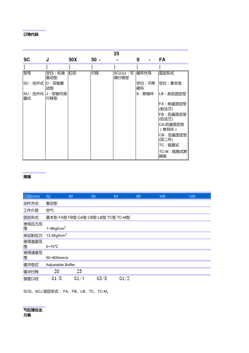
SC系列气缸选型样本SC系列气缸订购代码SC J 50X 50 - 25 - S - FA规格口径(mm) 32 40 50 63 80 100 125 动作方式复动型工作介质空气固定形式基本型FA型FB型CA型CB型LB型TC型TC-M型使用压力范围1~9Kgf/cm2保证耐压力13.5Kgf/cm2使用温度范围0~70℃使用速度范围50~800mm/s缓冲型式Adjustable Buffer缓冲行程20 25接管口径G1/8 G1/4 G3/8 G1/2SCD、SCJ 固定形式:FA、FB、LB、TC、TC-M。
气缸理论出力表气缸内径32 40 50 63 活塞外径12 16 20 20动作型式复动型复动型复动型复动型压侧拉侧压侧拉侧压侧拉侧压侧拉侧受压面积8.04 6.9 12.56 10.55 19.63 16.49 31.17 28.03空气压力(Kgf/cm)21 8.04 6.9 12.56 10.55 19.63 16.49 31.17 28.032 16.08 13.8 25.12 21.1 39.26 32.98 62.34 56.063 24.12 20.7 37.68 31.65 58.89 49.47 93.51 84.094 32.16 27.6 50.24 42.20 78.52 65.96 124.68 112.125 40.20 34.5 62.80 52.75 98.15 82.45 155.85 140.156 48.24 41.4 75.36 63.30 117.78 98.94 187.02 168.187 56.28 48.3 87.92 73.85 137.41 115.43 218.19 196.218 64.32 55.2 100.48 84.40 157.04 131.92 249.36 224.249 72.36 62.1 113.04 94.95 176.67 148.41 280.53 252.27气缸内径80 100 125 活塞外径25 25 35动作型式复动型复动型复动型压侧拉侧压侧拉侧压侧拉侧受压面积50.26 45.36 78.53 73.62 122.7 114.6空气压力(Kgf/cm2) 1 50.26 45.36 78.53 73.62 122.7 114.62 100.52 90.72 157.06 147.24 245.4 229.23 150.78 136.08 235.59 220.86 368.1 343.84 201.04 181.44 314.12 294.48 490.8 458.45 251.30 226.80 392.65 368.10 613.5 573.06 301.56 272.16 471.18 441.72 736.2 687.67 351.82 317.52 549.71 515.34 858.9 802.28 402.08 362.88 628.24 588.96 981.6 916.89 452.34 408.24 706.77 662.58 1104.3 1031.4 行程口径(mm) 标准行程最大行程容许行程32 25 50 75 100 125 150 175 200 250 300 350 400 450 500 1000 2000 40 25 50 75 100 125 150 175 200 250 300 350 400 450 500 600 700 800 1200 2000 50 25 50 75 100 125 150 175 200 250 300 350 400 450 500 600 700 800 900 1000 1200 2000 63 25 50 75 100 125 150 175 200 250 300 350 400 450 500 600 700 800 900 1000 1500 2000 80 25 50 75 100 125 150 175 200 250 300 350 400 450 500 600 700 800 900 1000 1500 2000 100 25 50 75 100 125 150 175 200 250 300 350 400 450 500 600 700 800 900 1000 1500 2000 125 25 50 75 100 125 150 175 200 250 300 350 400 450 500 600 700 800 900 1000 1500 2000外型尺寸尺寸表口径/符号 A A1 A2 B C D E F G H I J K L32 140 187 182 47 93 27 32 15 27.5 22 17 6 M10×1.25 M640 142 191 185 48 93 31 34 15 27.5 24 17 7 M12×1.25 M6 50 150 207 196 57 93 36.5 42 15 27.5 32 23 8 M16×1.5 M6 63 153 210 199 57 96 36.5 42 15 27.5 32 23 8 M16×1.5 M8 80 183 258 242 75 108 47 54 21 33 40 26 10 M20×1.5 M10 100 189 264 248 75 114 47 54 21 33 40 26 10 M20×1.5 M10 125 218 312 28694 124 55 64 30 33 45 35 11 M27×2 M12 160 311 454 418 143 168 63.5 103 40 50 72 12 M36×2 M16口径/符号M N O P Q R S T V W32 9.5 13.7 G1/8 3.5 7.5 7 45 33 12 1040 9.5 13.5 G1/4 6 8.2 9 50 37 16 1450 9.5 13.5 G1/4 8.5 8.2 9 62 47 20 1763 9.5 13.5 G3/8 7 8.2 8.5 75 56 20 1780 11.5 16.5 G3/8 10 9.5 14 94 70 25 22100 11.5 16.5 G1/2 11 9.5 14 112 84 25 22 125 12 16.5 G1/2 10 7.5 10 138 110 32 29 160 12 25 G1/2 9 180 140 40 36。
气缸标准缸径规格型号
气缸标准缸径规格型号1. 引言气缸是一种用于产生机械运动的装置,常用于工业生产中的各种机械和设备。
气缸的缸径是指气缸内部活塞移动的直径,是气缸的重要参数之一。
本文将介绍气缸标准缸径规格型号的相关内容。
2. 气缸标准缸径气缸的标准缸径是根据国际标准规定的一系列标准尺寸。
在工业领域,常用的气缸标准缸径一般为20mm、25mm、32mm、40mm、50mm、63mm、80mm、100mm、125mm、160mm、200mm等。
不同的应用场景和工作要求可能需要不同尺寸的气缸缸径。
3. 气缸规格型号气缸的规格型号是根据不同的制造商和市场需求制定的,用于标识气缸的具体参数和特性。
常见的气缸规格型号一般由字母和数字组成,例如SC50X100,其中SC表示气缸的类型、50表示缸径为50mm、100表示活塞行程为100mm。
气缸的规格型号除了包括缸径和活塞行程,还可能包括其他重要参数,如安装形式、工作压力、工作温度、密封方式等。
不同的规格型号适用于不同的工作场景,用户可以根据具体需求选择合适的气缸。
4. 气缸的选择和应用在选择气缸的时候,需要根据实际工作要求综合考虑多个因素。
首先需要确定所需的缸径大小,根据所需的推力和速度来确定合适的缸径。
另外,还需要考虑气缸的工作压力、温度和密封方式等参数,以确保气缸能够正常工作并满足工作要求。
气缸广泛应用于各个行业的自动化设备和生产线中。
常见的应用包括机械制造、汽车制造、机床、冶金、航空航天等领域。
不同的行业和应用场景对气缸的要求可能会有所不同,因此在选择和应用气缸时需要仔细考虑。
5. 气缸标准缸径规格型号的优势气缸标准缸径规格型号的使用可以带来多个优势。
首先,标准缸径能够提高气缸的通用性,方便用户选择和替换。
其次,规格型号的标识清晰明确,便于识别和查询。
另外,标准化的设计和制造能够提高气缸的生产效率和质量稳定性。
6. 结论气缸标准缸径规格型号是气缸的重要参数之一,决定了气缸的工作性能和适用范围。
液压缸型号意义
液压缸型号意义YHG型液压缸有E、G两种压力级、17种缸径、缸头、缸尾均设有单向放气阀。
适用于冶金、矿山设备等液压系统中。
1三、YHG型冶金设备标准液压缸 1YHG型液压缸结构图 1四、ZQ型重型冶金设备液压缸ZQ型液压缸具有性能良好、可靠性好等优点,广泛用于重型机械、冶金、矿山等行业。
型号意义五、DG型车辆用液压缸DG型车辆用液压缸为双作用单活塞杆液压缸,一般采用拧入式缸头与捍接缸底结构,具有重量轻、拆装简便等优点,工作压力?16MPa。
主要用于车辆、工程机械,起重运输机械、矿山机械及其它机械的液压传动系统中。
型号意义六、RG型拉杆式液压缸RG型拉杆式液压缸结构紧凑、重量轻。
安装形式多样,并容易变换、易装易拆、零件通用化高、维修方便,具有轻量化、适用化、可靠性高等特点。
广泛用于轻工、纺织、橡塑、冶金、化工、矿山、行走机械等液压传动系统中。
型号意义二、HSG型工程用液压缸HSG型工程用液压缸为单活塞杆双作用式液压缸,主要用于各种工程机械、起重机械、运输机械、船舶机械、冶金矿山机械及工程车辆的液压传动系统中。
JB2162-77系列液压缸技术参数1、适用范围:本标准油缸适用于额定压力,P?16MPa,周围介质温度为-20,+80?的冶金设备重型机械,亦可用于其它行业之中。
2.基本参数: 见表额定压力 MPa 活塞行程缸径活塞面积活塞杆活塞杆端活塞杆直径S mm D 面积有效面积 6.3 10 16 dmm 222mm Acm A1cm A2cm 最小最大推力拉力推力拉力推力拉力 50 50 500 28 19.64 6.16 13.48 1240 850 1960 1350 3140 216063 60 630 35 31.17 9.62 21.55 1960 1357 3117 2155 4990 3450 80 80 800 45 50.27 15.8 34.37 3160 2170 5030 3440 8000 5500 100 100 1000 55 78.54 23.79 54.78 4950 3450 7850 5480 12570 8760 125 125 1250 70 122.7 38.48 84.22 7725 5320 12270 8420 19630 13500 160 160 1600 90 201.0663.62 137.44 12670 8660 12670 13740 32170 22000 200 200 2000 110 314.2 95.03 219.17 19790 13800 19790 21920 50270 35000 250 250 2500 140 490.87 153.94 336.93 30925 30925 30925 33693 78540 53910型号意义JB2162 × -安装形式缸盖连接方式机械工业部标准油缸直径行程 G-脚架B-中间S-尾部2-法兰 1-杆接式固定式摆动式悬挂式式DG型车辆用液压缸1、型号说明DG - J C - E1活塞杆联接形式单活塞双作用液压缸重型活塞杆液压缸内径压力等级:8,16MPa 安装方式:单耳环式 L:螺纹式 E:耳环式液压缸内Φ M L Φ2×H2 2-Φ1 R×H1 2-Φ3 2-M1 F H P Q S S1 径D50 70 M24×1.5 33 56×40 20 25×28 30 M18×1.5 52 15 32 65 242 272 63 83 M30×2 36 60×60 32 30×40 35 M22×1.5 67 15 35 70 272 310 80 102 M42×2 42 80×75 40 40×50 35 M22×1.5 70 15 50 85 308 359 110 127M48×2 62 100×95 50 50×63 45 M27×2 81 20 60 102 369 427 110 140M56×2 70 115×105 55 55×75 45 M27×2 85 20 65 118 404 472 125 159M64×3 73 124×118 63 62×80 45 M27×2 90 20 70 129 421 486 140 168M72×3 75 130×125 65 71×80 55 M33×2 95 20 80 144 460 540 150 185M80×3 80 140×135 70 80×85 55 M33×2 101 20 81 145 481 565 160 194M80×3 85 160×145 80 90×95 55 M33×2 115 20 90 168 528 613 180 219M90×3 95 179×160 90 100×105 65 M42×2 126 20 105 185 606 716 200 245 M100×3 105 184×170 100 100×120 65 M42×2 157 20 110 200 680 800 220 273 M110×3 112 200×120 100 200×120 65 M42×2 157 20 120 200 693 811 250 299 M125×4 125 220×130 110 110×136 65 M42×2 157 20 130 210 716 831320 402 M160×4 166 280×170 140 140×176 70 M48×2 200 24 160 264 847 1017YG、Y-HG1液压缸系列液压缸活塞的理论输出推力和拉力输出推力KN 输出推力KN 缸速度活塞杆直径径工作压力MPa 工作压力MPa 比φ mm mm 6.3 8 10 12.5 16 6.3 8 10 12.5 161.25 18 6.31 3.01 10.02 12.53 16.04 40 7.29 10.05 12.57 15.71 20.111.46 22 4.88 7.01 8.77 10.96 14.022 28 4.04 5.12 6.41 8.01 10.251.25 22 9.98 12.67 15.83 19.79 25.34 50 12.37 15.71 19.63 24.5431.42 1.46 28 8.49 10.78 13.47 16.84 21.572 35 5.96 7.57 9.45 11.82 15.131.25 28 15.76 20.01 25.01 31.26 40.04 63 19.64 24.94 31.17 38.97 49.88 1.46 35 13.22 16.80 20.99 26.25 33.592 45 9.62 12.22 15.27 19.09 24.431.25 35 25.26 32.07 40.09 50.11 64.14 80 31.67 40.21 50.27 62.83 80.42 1.40 45 21.65 27.48 34.36 42.95 54.972 55 16.15 20.51 25.64 32.04 41.011.25 45 39.46 50.11 62.64 78.72 100.21 100 49.48 62.83 78.54 98.17 125.66 1.46 55 33.98 43.13 53.91 67.38 86.252 70 25.23 32.04 40.06 50.34 64.091.25 55 61.79 78.47 98.09 122.61 156.94 125 77.31 98.17 122.72153.40 196.35 1.46 70 53.07 67.38 84.24 105.29 134.772 90 37.23 47.27 59.10 73.37 94.561.25 70 102.42 130.06 162.58 203.22 260.12 160 126.67 160.85 201.06 251.33 321.70 1.46 90 86.59 109.96 137.44 171.81 219.912 110 56.80 84.82 106.03 132.54 169.64注:实际选用时负载率取50-70%缸内径标准行程备注4050 63 40、50、63、80、100、125、160、最长行程一般不超过 80 200、250、320、400、500、630、缸内径的10倍 100 800、1000、1250、1600 125 160\YG、Y-HG1液压缸系列1、图形符号2、YG系列双作用单活塞杆标准液压缸主要技术参数额定压力:6.3MPa ;16MPa 耐压:额定压力的150%最低启动压力:0.3MPa温度范围:-10,+80?极限速度:300mm/s工作介质:矿油型液压油3、型号说明YG - ? D / d × ? ? ?压力等级安装方式附加装置缸内径杆径行程 MF1:前MF2:后MF5:前MF6:后H:有缓无缓液压缸 C:6.3MPa J:基本MP3:后MS1:端MT4:中间销 mm mm mm E: 16MPa 端矩形端矩形端方形端方形法冲冲省型端单耳环部角架轴法兰法兰法兰兰略YG、Y-HG1液压缸系列冶金设备用Y-HG1系列双作用单活塞杆型标准液压缸1、主要技术参数:额定压力:6.3MPa ; 16MPa耐压:额定压力的150%最低启动压力:0.3MPa温度范围:-40,+80?极限速度:300mm/s工作介质:液压油、机械油、高水基乳化液2、型号说明:Y - HG1 - ? D / d × ? L ? - ? L ?双压力等极安装方式附加工作介质作装置用油冶活缸杆口 F3: F4: 金塞内杆行端E: 螺前后J1:无液杆径径程外J:F1:F2:F5:F6:尾H:O: W: 纹端端Z2:轴缓机压第mm mm mm 螺C: E: 基前端后端前端后端部有液乳连圆圆中间向冲械缸一纹 6.3MPa 16MPa 本矩形矩形方形方形单缓压化接形形销轴角省油种型法兰法兰法兰法兰耳冲油液法法架略类环兰兰型YZ系列液压泵站1、型号注释YZD B 2.5 63 单吸叶片泵 L 上置立式 C 6.3 L 冷却器 100S 名额 E 16 160 双联叶片泵油箱称定辅助装F 20 250 容量 X 蓄能器代 W 上置卧式压 B 置 400 升变量叶片泵号力 630 H 32 G 加热器 MPa C 齿轮泵 S 1000 旁置式 E 柱塞泵2、外形尺寸1-液压泵 2-溢流泵 3-卸荷阀 4-单向阀型号YZL-63D YZL-63S YZL-100D YZL-100S YZW-100B YZL-160D YZL-160S YZW-160B YZL-250D YZL-250S YZW-250B YZW-220S YZW-400D YZW-400S YZW-400B YZW-630 尺寸mmA 690 690 710 710 710 840 840 840 970 970 970 970 1190 1190 1190 1490B 470 470 530 530 630 620 620 720 720 720 830 830 920 920 920 1050H 800 800 990 1010 830 1040 1040 880 1130 1130 960 960 980 980 980 10503、用途液压泵站由油箱、泵装置、液压集成系统及其它附件组成。
MB1汽缸样本SMC

F
13 13 14 14 20 20
G
13 14 15.5 16.5 19 19
H
47 51 58 58 72 72
MB
4 4 5 5 5 5
J
M6×1.0 M6×1.0 M8×1.25 M8×1.25 M10×1.5 M10×1.5
K
6 6 7 7 10 10
MM
M10×1.25 M14×1.5 M18×1.5 M18×1.5 M22×1.5 M26×1.5
1 /8
63
80
100
单杆双作用
使用压力范围 MPa 环境和流体温度 给油 活塞速度 缓冲
双杆双作用
行程长度允差 mm 接管口径
Rc 1/4
Rc 3/8
Rc 1/2
*如给油,请用透平1号油ISOVG32。
标准行程/磁性开关型号表
缸径mm 标准行程 mm 32 25、50、75、100、125、150、175、200、 250、300、350、400、450、500 40
* 垫缓冲的场合,气缸总长度增长,ø32 • ø40为6mm,ø50•ø63为8mm,ø80•ø100为10mm。
1.21
外形尺寸图 (毫米) 基本型
MM G
2-Rc P
* 对双杆双作用气缸为法兰型。 **双杆双作用气缸没有这3种安装形式。
G
缓冲阀
W
V
通口
øE øD
øE
无气m)
16
2×4-J
缸径 (mm)
S
ZZ
缸径 (mm)
S
ZZ
A H
K F
N
S+行程 ZZ+行程
N
□C □B
CUJ-S选型资料
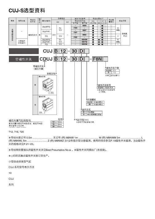
CUJ-S选型资料12, 16, 20※导线长度记号 0.5m …………………… ⽆记号 (例) M9NW 1m …………………… M (例) M9NWM 3m …………………… L (例) M9NWL 5m …………………… Z (例) M9NWZ 注1)2⾊指⽰型注意磁滞。
使⽤的场合参见P.19磁性开关磁滞。
注2)磁性开关的规格详见P.21~23。
※导线带前置插头的磁性开关详见Best Pneumatics No.w 。
※磁性开关同捆出⼚(未组装)。
※○印的⽆触点磁性开关按订货⽣产。
⼩型⾃由安装型⽓缸CUJ 系列型号表⽰⽅法10CUJ系列OUTIN规格※根据回路条件,有不满⾜最⾼活塞速度的场合。
※⽤⽓缸返回侧的推⼒(弹簧反⼒)推负载,会成为⾏程不良的要因。
理论输出⼒表/双作⽤型第⼀安装载荷重的弹簧状态第⼆安装载荷重的弹簧状态压缩空⽓进⼊让⽓缸处于缩回状态弹簧让⽓缸处于复位状态弹簧反⼒/单作⽤弹簧压回型质量表/双作⽤型单作⽤弹簧压回型图形符号双作⽤/单杆型单作⽤/弹簧压回型11安装⽅法:备有通孔安装螺钉。
订购⽅法:在使⽤螺钉的前⾯追记「CUJB -」。
例)CUJB -M5×30L安装⽅法轴向安装侧向安装⽆磁性开关(⽆磁⽯)※安装⽓缸时,必须使⽤附属的弹簧垫圈。
※左记订购型号为安装螺钉1只、弹簧垫圈1个同捆包装。
带磁性开关(磁⽯内置)⼩型⾃由安装型⽓缸CUJ 系列CUJ系列规格外形尺⼨图与标准/双作⽤型相同。
参见P.11。
但使⽤活塞速度为50~400mm/s 。
侧向安装/C □UJB轴向安装/C □UJS ■洁净系列型号表⽰⽅法13⼩型⾃由安装型⽓缸CUJ 系列构造图双作⽤型单作⽤弹簧压回型⽆磁⽯杆端外螺纹磁⽯内置磁⽯内置⽆磁⽯可换件/密封圈组件※密封圈组件!3~!5为⼀组,按各缸径的订购型号订货。
※仅需要润滑脂包的场合,按下记型号订购。
润滑脂型号:GR-L-005(5g) 14CUJ系列单作⽤弹簧压回型的场合单作⽤弹簧压回型的场合侧向安装⽆磁⽯/CUJB磁⽯内置/CDUJB杆端外螺纹的场合杆端螺母外形尺⼨图双作⽤型/单作⽤弹簧压回型 ?12, ?16, ?20※( )内尺⼨为单作⽤弹簧压回型。
SMC气缸样本

6,10,15,20,25,32 6,10,15,20,25,32 10,16,20,25,32 12,16,20,25,32,40
12,16,20,25,32,40,50,63,80100
20,25,32,40,50,63,80,100 20,25,32,40,50 6,10 40,63,100 8,12,16,20,25,32,40
300
32
600
-
40
800
-
50
1000
-
Байду номын сангаас
63
1100
-
80
1200
-
100
1300
-
*最大行程依型号而异。
叶片式
轴
轴
叶片
摆台
摆台
齿轮齿条式
轴轴
摆台
摆台
平行开闭型
方形
2爪
圆柱形
2爪
3爪
4爪
支点开闭型
方形 2爪
高速,高频,低速,低摩擦 夹紧
止动气缸
复合动作
缓和冲击 高速
双倍输出力 带测程功能
立体搬送
0.1
1
10
100
1000
(kg)
3
~10
0.2
4
~20
0.6
6
~60
1.4
8
2.5
10 ~400
12
3.8 5.5
16
9.8
20
15
25
24
32
39
40 ~1500
50
62 96
63
机械毕业设计593定尺机装置设计毕业设计
(4)销轴的截面魔模数为ZP=πd3/16=54cm3.
(5)材料的拉伸屈服点δs=300.
4
气缸的选型及气缸的特点:
在看到气缸二字时,也许大家会问,为何不选油缸呢?这里先介绍一下气缸传动的优缺点。
4
1、对于传动形式而言,气缸作为线性驱动器可在空间的任意位置组建它所需的运动轨迹,安装维护简单。
2、工作介质是取之不尽,用之不竭的空气,空气本身不花钱,排气处理简单,不污染环境,成本低,压力等级低,使用安全。
已介绍了钢铁工业与国家的关系及其重要的作用。大家可以说都见过钢铁,但我想大家并不一定知道钢铁的生产过程。我国可以说是冶铁有着悠久的历史了。在我国春秋时期已有冶金的历史了。大家可以从历史书上得知钢铁的生产过程,但现在已是二十一世纪了,钢铁的生产过程也不可能像过去那样的了。下面就简单介绍一下钢铁的生产过程:铁矿石——铁水——毛坯——所需规格钢铁——检验合格——成品。
上面只是棒材的粗略的生产线,在这其中将有许多的工艺过程。
例:在毛坯到所需规格钢材时中间的工艺过程。砂轮锯后定尺型钢材料——检查台架前辊道——检查台架前辊齐头——上钢装置——水平移送装置——下钢装置——检查台架后辊道——过跨检查台前辊道——改尺辊——固定挡板——双面挡板齐定尺——锯切——短尺型钢移送练——平移堆垛收集台车——收集槽——打件,待吊运——检验,合格——成品。
1、引言
定尺机装置是在学完了机械设计和有关的专业课,并在生产实习的基础上进行的一个设计环节.这是我们在对毕业设计的一次深深的总复习,也是一次理论联系实际的训练.因此,在毕业设计中占有重要的地位.
就我个人而言,希望通过这次毕业设计,对自己今后将从事的工作,进行一次适应性的训练,通过设计锻炼自己分析问题,解决问题的能力,为以后的工作打下一个良好的基础.
ISO标准空气气缸55-C96 -SMX62EN产品说明书
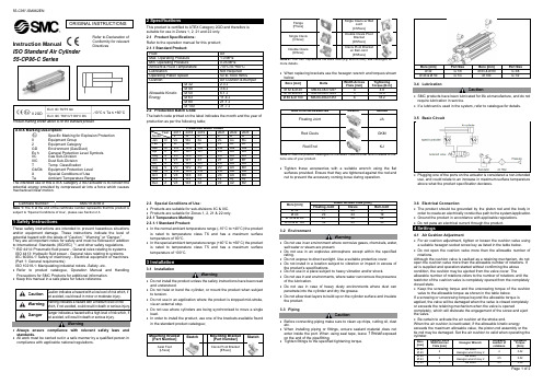
Instruction Manual ISO Standard Air Cylinder 55-CP96-C SeriesProduct marking shown above is for the standard product.II 2potential energy provided by compressed air into a force which causes mechanical linear motion. subject to “Special Conditions of Use”, please see Section 2.3.1 Safety InstructionsThese safety instructions are intended to prevent hazardous situations and/or equipment damage. These instructions indicate the level of potential hazard with t he labels of “Caution,” “Warning” or “Danger.” They are all important notes for safety and must be followed in addition to International Standards (ISO/IEC) *1), and other safety regulations. *1)ISO 4414: Pneumatic fluid power - General rules relating to systems. ISO 4413: Hydraulic fluid power - General rules relating to systems.IEC 60204-1: Safety of machinery - Electrical equipment of machines. (Part 1: General requirements)ISO 10218-1: Manipulating industrial robots -Safety. etc.∙ Refer to product catalogue, Operation Manual and Handling Precautions for SMC Products for additional information. ∙ Keep this manual in a safe place for future reference.not avoided, will result in death or serious injury.Warning∙ Always ensure compliance with relevant safety laws and standards.∙ All work must be carried out in a safe manner by a qualified person in compliance with applicable national regulations.2 SpecificationsThis product is certified to ATEX Category 2GD and therefore is suitable for use in Zones 1, 2, 21 and 22 only. 2.1 Product Specifications:Refer to the operation manual for this product;The batch code printed on the label indicates the month and the year of production as per the following table;2.3 Special Conditions of Use:∙ Products are suitable for sub-divisions IIC & IIIC. ∙ Products are suitable for Zones 1, 2, 21 & 22 only. 2.3.1 Temperature Marking: 2.3.1.1 Standard Product:∙ In the normal ambient temperature range (-10°C to +40°C) the product is rated to temperature class T6 and has a maximum surface temperature of 80°C.∙ In the special ambient temperature range (+40°C to +60°C) the product is rated to temperature class T5 and has a maximum surface temperature of 100°C.3 Installation3.1 InstallationWarning∙ Do not install the product unless the safety instructions have been read and understood.∙ Do not twist or bend the cylinder, or mount the product when subject to tension.∙ Do not use in an application where the product is stopped mid-stroke, via an external stop.∙ Do not use where cylinders are being synchronised to move a single load.∙ In order to install the product, use one of the brackets available found in the standard product catalogue;represents the Bore Size (e.g. Ø40 is 040), see catalogue for more details.∙ When replacing brackets use the hexagon wrench and torques shown SketchSee the product catalogue for the exact code to order which relates to the bore size of your product.∙ Tighten these accessories with a suitable wrench using the flat surfaces provided. Ensure that they are tightened against the rod end nut to prevent the accessory coming loose during operation.3.2 EnvironmentWarning∙ Do not use in an environment where corrosive gases, chemicals, water, salt water or steam are present.∙ Do not use in an explosive atmosphere except within the specified rating.∙ Do not expose to direct sunlight. Use a suitable protective cover.∙ Do not install in a location subject to vibration or impact in excess of the product’s specifications .∙ Do not use in a place subject to heavy vibration and/or shock.∙ Do not use in wet environments, where water can remove the presence of the lubrication.∙ Do not use in case of heavy dusty environments where dust can penetrate into the cylinder and dry the grease.∙ Do not allow dust layers to build up on the cylinder surface and insulate the product.3.3 PipingCaution∙ Before connecting piping make sure to clean up chips, cutting oil, dust etc.∙ When installing piping or fittings, ensure sealant material does not enter inside the port. When using seal tape, leave 1 thread exposed on the end of the pipe/fitting.∙ Tighten fittings to the specified tightening torque.Bore [mm] Port Size Bore [mm] Port Size 3.4 LubricationCaution∙ SMC products have been lubricated for life at manufacture, and do not require lubrication in service.∙ If a lubricant is used in the system, refer to catalogue for details.3.5 Basic Circuit∙ Plugging one of the ports on the actuator is considered a non-intended use, and could relate to an increase in maximum surface temperature above what the product specification declares.3.6 Electrical Connection∙ The product should be grounded by the piston rod and the body inorder to create an electrically conductive path to the system/application. ∙ Ground the product in accordance with applicable regulations. ∙ Do not pass an electrical current through the product.4 Settings4.1 Air Cushion Adjustment∙ For air cushion adjustment, tighten or loosen the cushion valve using a suitable hexagon socket screw key as listed in the table below.∙ Do not open the cushion valve more than the allowable number of rotations.Although the cushion valve is caulked as a retaining mechanism, do not open the cushion valve more than the allowable number of rotations. If air is supplied and operation started without confirming the above condition, the cushion may be ejected from the valve cover. Theallowable number of rotations refers to the number of rotations until the restrictor of the cushion valve is completely opened from the completely closed state.∙ Keep the screwing torque and the unscrewing torque of the cushion valve to the allowable torque as shown in the table below.If a screwing or unscrewing torque beyond the allowable torque isapplied, the valve will be damaged when the valve is closed completely or exceeds the retaining mechanism when the valve is openedcompletely, which will dislocate the engagement of the screw and eject the valve.∙ Be certain to activate the air cushion at the stroke end.When the air cushion is inactivated, if the allowable kinetic energyexceeds the maximum allowable value, the piston-rod assembly or the tie rod may be damaged. Set the air cushion to valid when operating theORIGINAL INSTRUCTIONSRefer to Declaration of Conformity for relevant Directivesstate.Using it in the fully closed state will cause the cushion seal to be damaged. Using it in the fully opened state will cause the piston rod assembly or the cover to be damaged.∙If the cushion valve is used in the fully open position adjust the speed5 How to OrderRefer to the standard product catalogue for ‘How to Order’.6 Outline Dimensions (mm)Refer to the standard product catalogue for general dimensions.7 Maintenance7.1 General MaintenanceCaution∙Not following proper maintenance procedures could cause the product to malfunction and lead to equipment damage.∙If handled improperly, compressed air can be dangerous.∙Maintenance of pneumatic systems should be performed only by qualified personnel.∙Before performing maintenance, turn off the power supply and be sure to cut off the supply pressure. Confirm that the air is released to atmosphere.∙After installation and maintenance, apply operating pressure and power to the equipment and perform appropriate functional and leakage tests to make sure the equipment is installed correctly.∙If any electrical connections are disturbed during maintenance, ensure they are reconnected correctly and safety checks are carried out as required to ensure continued compliance with applicable national regulations.∙Do not make any modification to the product.∙Do not disassemble the product, unless required by installation or maintenance instructions.∙Do not use a product which looks or contains damage, this will invalidate the certification. If damage is seen, please replace the product immediately.∙Periodically check the product for any damage or rust appearing. This could result in an increase in friction and lead to dangerous conditions. Replace the whole actuator if any of these conditions appear.∙Periodically check the condition of the rod seal and for the presence of lubrication, where possible. If these areas appear to be dry, please follow the lubrication procedure.∙Replace the seals, when air leakage is above the allowable value given7.2 Disassembly Procedure∙Loosen and disassemble the tie rods and tie rod nuts using suitable ∙Clear away the old grease and place all of the parts on a clean cloth ina clean environment.∙Remove the old tube gaskets, rod seal, cushion seals, piston seal and wear ring using a fine screwdriver where necessary.Caution ∙If a magnet is present on the piston do not remove it. The magnet isnot replaceable.7.3 Seal Replacement Part NumbersWarningOnly use SMC seal kits as listed in the table below;Caution∙ A wear ring is not fitted to double rod cylinders.7.4 Lubrication Procedure∙Apply lubricant to:• The rod seal and the rod bush.• The piston outer surface and piston seal groove.• The piston seal, tube gaskets and cushion seals.• The piston rod surface and cylinder tube internal surface.∙Lubricate the parts with the grease packs provided with the seal kit.The amount of lubricant to be applied is listed in the following table.7.5 Reassembly Procedure∙Insert the new seals into the appropriate seal groove.∙Insert the piston rod assembly into the cylinder tube. Be careful not todamage the piston seal.∙Attach the covers to the cylinder tube. Be careful not to damage thetube gaskets and rod seal.∙Screw the tie rod nuts onto the tie rod on the end with the short thread.∙Insert the tie rod assemblies into appropriate holes in the head cover.∙Screw the tie rods into the rod cover. Tighten the diagonally oppositeØ 80 & Ø 100 18.2Warning∙Mounting precision is required for the trunnion type cylinder. It isdifficult to align the axial centre of the trunnion with the axial centre ofthe cylinder. When reassembling the cylinder, take care with thetrunnion location accuracy.Caution∙Ø80 and Ø100 use flat washers on the tie rod nuts.8 Limitations of Use8.1 Limited warranty and Disclaimer/Compliance RequirementsRefer to Handling Precautions for SMC Products located on .8.2 Obligations of the end-user∙Ensure the product is used within the specification outlined.∙Ensure that the maintenance periods are suitable for the application.∙Ensure any cleaning processes to remove dust layers are made withthe atmosphere in mind (e.g. using a damp cloth to avoid static buildup).∙Ensure that the application does not introduce additional hazards bymounting, loading, impacts or other methods.∙Ensure that there is sufficient ventilation and air circulation around theproduct.∙If the product is subject to direct heat sources in the application, theyshould be shielded so that the actuator temperature stays within thestated operating range.Caution∙SMC products are not intended for use as instruments for legalmetrology.Measurement instruments that SMC manufactures or sells have notbeen qualified by type approval tests relevant to the metrology(measurement) laws of each country.Danger∙Do not exceed any of the specifications listed in Section 2 of thisdocument as this will be deemed improper use.∙Air equipment has an air leakage during operation within certain limits.Do not use this equipment when the air itself introduces additionalhazards and could lead to an explosion.∙Use only ATEX certified auto switches. These should be orderedseparately.∙Do not use this product in the presence of strong magnetic fields thatcould generate a surface temperature higher than the productspecification.∙Avoid applications where the piston rod end and the adjoining part inthe application can create a possible ignition source.∙Do not install or use these actuators where there is the possibility forthe piston rod to impact foreign objects.∙In the event of damage or failure of any parts located in the vicinitywhere this product has been installed, it is the responsibility of the userto determine whether or not this has compromised the safety andcondition of this product and/or the application.∙External impact on the cylinder body could result in a spark and/orcylinder damage. Avoid any application where foreign objects can hitor impact the cylinder. In such situations the application should installa suitable guard to prevent this occurrence.∙Do not use this equipment where vibration could lead to failure.9 ContactsRefer to Declaration of Conformity and for contacts.URL : http// (Global) http// (Europe)'SMC Corporation, Akihabara UDX15F, 4-14-1, Sotokanda, Chiyoda-ku, Tokyo 1010021Specifications are subject to change without prior notice from the manufacturer.© 2018 SMC Corporation All Rights Reserved.Template DKP50047-F-085H。
汽缸体3

1900038135442222M10×45-8.8-ZN DIN939双头螺柱Stud62876947628769476287692119000381352733333333333M10×28-8.8-ZN DIN939双头螺柱Stud 2219000388845233333333333VM10-8-ZN DIN9802型全金属六角锁紧螺母Self-locking nut 231900039016042222222222212m6×20 DIN7圆柱销Straight pin 24VG1500019045A 11111111111油气分离器总成Oil separator 25VG12G0004003811111111111带纤维夹层橡胶软管Hose 261900039893011111111111125/35 N05074软管卡箍Hose clamp 271900039893362222222222216/25-ZN N05074软管卡箍Hose clamp 28VG260001110611111111无纤维夹层橡胶软管Hose VG1500010176111无纤维夹层橡胶软管Hose 29VG1401008611111111111加油短管垫片Oil filler gasket 30VG156001002811111111111加油短管组件Oil filler 3119000393108244444444444B6 DIN127轻型弹簧垫圈Spring lockwasher 3219000380232144444444444M6×16-8.8-ZN DIN933六角头螺栓Hex head bolt 331900039893062222222222238/57-ZN N05074软管卡箍Hose clamp 34VG150001007911111111111带纤维夹层的橡胶软管Hose 35VG26000109191111机油加油管组件Oil filler neck VG26000105651111机油加油管组件Oil filler neck VG26000111691111机油加油管组件Oil filler neck VG1500010004111机油加油管组件Oil filler neck 36VG260001048911111111加油管盖总成Oil filler cap 37Q734B265026511111111111O型橡胶密封圈Sealing ring 黄河王子发动机型号 \ 件数气缸体(三) Cylinder Block序号No.图号Part No.规格标准Standard Specification 零件名称Part Name 斯太尔 STEYR 豪泺 HOWO。
