LG 42LC7R-TA液晶彩电维修手册
液晶电视维修手册
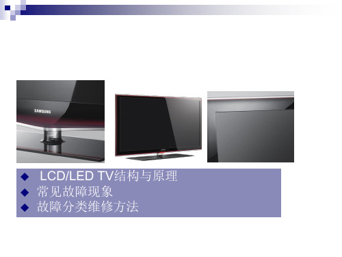
*以LA40A750为例
8
I. LCD TV内部结构(IP电源)
T – CON 板
CN1
CNI803 CN103 CNI806 CN801
CN6105_FFC CN6001_LCD
背光驱动 (BL Driver)
IP电源板 (IP Board)
CNI801 CNI802
CN1001
主板 (Main Board)
2%
yes
⑤
FRCM测试故障?
no no
yes
⑥
T-Con板不 良
5% 更换LVDS线后 是否有故障?
FBE测试故障?
yes
no
no
更换T-Con板后 是否有故障?
LVDS线不良 yes
77%
yes
液晶屏不良
16
III-3. 间歇性无图像
非故障检查项目: 检查是否电源线接触不良? 故障检查项目:
故障发生时待机 灯是否点亮?
24
注意:具体型号接口定义以维修手册为准
附. 排线接口检测方法
接口④------屏幕亮度(Dimming)控制(部分型号Dimming控制端在主板电源接口中)
PIN NAME 1 SW_inverter 2 Ana_dimming 3 PWM_dimming 4 GND 5 GND
功能定义:
-- SW_inverter -- Ana_dimming -- PWM_dimming 控制屏幕逆变器 约5V 屏幕明暗控制 屏幕明暗控制PWM方式, 占空比 40%~90%
no no
3%
yes
⑥
FBE测试故障?
18% 更换LVDS线后 是否有故障?
yes
LG 42LC7R 等离子电视机 说明书

26LC7R* 32LC7R*26LC4R* 32LC4R*42PC5R* 42PC5RV*12) 4 ()8263237*32LB9R*PREPARATION ........................................................4...................................................6....................................................832LB9R*8.........................................9.........................................10......................................................12.................................... 13......................................................14PICTURE CONTROL PIP ().........................................46() ..........................48- - .....................................50- .........51- - ..................52- ..................53- ...................................54...................................................55..................................................56...........................................57.................................................58......................................................59..............................................................60...............................................61- .....................62..........................63.............................................................64/ .................................65I/II - / ..............................66- .........................67- .............................67.. (68)HD ..........................................15DVD .........................................18..................................................21A/V ......................................24...........................................25..............................................26- PC ...........................28............................................32.....................................................34.....................................................34.......................................................34...............................35......................................................36......................................................37..............................................................38...............................................39.....................................................40.....................................................41..............................................42.............................................................43...................................................44/ .. (12)3 (76) (78) (79)......................................81 (69) (70) (71) (72)/ ..................................................73SIMPLE TEXT() (73)TOP TEXT (74)FASTEXT (74) (75)■■42/50PC5R*••••26/32/37/42LC4R*••••1126■S-VIDEOS-Video//S-VIDEOS-Video//1242/50PC5R*(HDMI)HDMI INHDMI DVI () HDMI/DVI RGB /PC / component / (AV IN 1)/1234S-VIDEOS-Video /2AUDIO OUT 7() 132LB9R*■-B B B1() * /()()■""""121"""""!B"" -■ 444444444COMPONENT IN2VARIABLEAUDIO OUTCOMPONENT IN■()()6561)12HDcomponentP R)COMPONENT IN VIDEOP R )COMPONENT IN AUDIO(Digital-STB)(Component 1COMPONENT IN2Component 2480i/576i ■■""VGA )12HDMI(Digital-STB)HDMI/DVI IN 1HDMI IN 2HDMI1HDMI2(Digital-STB)(BHDMIB HDMI 1280x720pBHDMI1280x720p!(Digital-STB)HDMI/DVI IN 1(Digital-STB)(Digital-STB)()(INPUT)HDMIDVI12DVDcomponentComponentDVDcomponentcomponentDVD COM-PONENT IN VIDEODVD AUDIODVD Component 1COMPONENT IN2Component2VIDEO L/MONO AUDIO RAV IN 2RCA1AUDIO/VIDEO =(==)S-VIDEOVIDEOLRANT IN2DVD (PLAY) (DVD DVDOUTPUT SWITCHANT OUT)13(INPUT) AV IN2HDMI DVI INAV1 AV2HDMI INAV IN IN 1 1 AV OUT AVVIDEOS-VideoVIDEO S-VIDEOL RR AUDIOL/MONOANT IN1 2HDMI INDVD S -VIDEO DVDS-VIDEOOUTPUT SWITCH ANT OUTAUDIOL/MONO MONOS-VIDEO123 4 5DVD (INPUT)DVD AV2ENT INMONO AUDIO R VIDEO L/MONOAV IN 2DVD19HDMI IN IN HDMI12 COMPONENT INHDMI1DVD HDMI HDMI IN 2 HDMI/DVI INHDMI/DVI IN HDMI DVI IN 1HDMI IN IN HDMI 212HDMI2(INPUT)HDMI13DVD1!B B BHDMI DVD DVD DVD 1280x720p (HDMI-DTV (kHz) 720x480 720x576 31.47 31.50 31.25 44.96 45.00 37.50 33.72 33.75 28.125 67.432 67.5 56.25 ) (Hz) 59.94 60.00 50.00 59.94 60.00 50.00 59.94 60.00 50.00 59.94 60 50 HDMI 1280x720p HDMI1280x7201920x1080i(VGA)1920x1080p20■ ■()ANT OUTS-VIDEOVIDEOLR1AV IN 1 AV OUTAUDIO (RGB/DVI)ANTENNA INL/MONOANT IN OUTPUT SWITCH21 2 3ANT OUTANTENNA INANT IN(PLAY)HDMI DVI INHDMI IN21VIDEO L/MONO AUDIO RVIDEO L/MONO AAV IN 2RCAS-VIDEOVIDEOLRANT INOUTPUT SWITCHANT OUT1HDMI DVI INHDMI INRGB(PC)AUDIO (RGB/DVI)AV IN IN 1 1 AV OUT AVVIDEOR AUDIOL/MONO1AUDIO/VIDEO = )L/MONO MONO(==2 3(INPUT) AV IN2 AV1 AV2(PLAY) ()!BAUDIO L/MONO22S-Video1S-VIDEO S -VIDEO (RCA )OUTPUT SWITCH ANT OUT VIDEO S-VIDEOL RANT IN2AUDIOS-VIDEO123(PLAY) ( (INPUT) AV2)4MONO AUDIO R VIDEO L/MONOAV IN 2!BS-VIDEOVIDEO S-VIDEOS-VHSHDMI DVI INHDMI INAV IN 1VIDEOR AUDIOL/MONO23A/VVIDEOLRS-VIDEOVIDEO L/MONO AUDIO R1AV IN 21(==AUDIO/VIDEO =)2(INPUT) AV IN1AV2 AV1324HDMI DVI INHDMI IN1 2VARIABLE AUDIO OUTVARIABLE AUDIO OUT1!B( (B 65 ))25D-sub 15 pinHDMI DVI IN HDMI INRGB INRGB(PC)AUDIO (RGB/DVI)AV IN 1 AV OUTAUDIO (RGB/DVI)12RGB OUTPUTAUDIO1 2 3 4RGBRGB (PC)AUDIO(INPUT)RGB PC26L/MONORGB(PC)!B B B BB BRGB (PC)1366x768 60Hz ( ) / 852x480 60Hz (42 WVGA ) / 1024x768 60Hz (42 XGA ) / 1360*768 60Hz (50 ) B SXGAB(B) RGB-PC 5(RGB-PC (kHz) 640x350 720x400 640x480 848x480 852x480 800x600 1024x768 1280x768 1360x768 1366x768 31.5 31.5 31.5 31.5 31.5 37.9 48.4 47.8 47.7 47.7) (Hz) 70.1 70.1 59.9 60.0 60.0 60.3 60.0 59.9 59.8 59.8!B VGA848x480 852x480 (VGA ) B XGA 1280x768 1360x768 1366x768 (XGA )27PC( RGB [PC] )LIST EXITMENUQ.VIEW SLEEPOKFAVVOL PRMUTE1 4 72 5 83 6 91(MENU)/2 3 4• •B/vV b B1B/BB(OK)vV b B2•RGB (PC)B5(EXIT)vV b B3 428Phase) PhaseClockRGB[PC]COMPONENT (480i/480p/576i/576p/720p/1080i)HDMI(480p/576p/720p/1080i/1080p(VGA))COMPONENT(480i/480p/576i/576p/720p/1080i)HDMI(480p/576p/720p/1080i/1080p(VGA))(MENU)////Phase ClockRGBVGA/XGARGB [PC](MENU)/ B/B/)B/VGA/XGA()()(MENU)///•STB(POWER)(TV INPUT)(INPUT)/(OK)(TV AV1AV2Component1Component2RGB PC HDMI1 HDMI2)(PIP PR - /+)(PIP INPUT)(SIZE)(POSITION)(PIP)/DVDDVD//b/B(OK)AV()(EXIT)(LIST)(MENU)(Q.VIEW)(SLEEP)32//■(++--)■1.5V AA■(TELETEXT BUTTONS)/(I/II)Simplink(B44))///)(OK)(/)(FAV)(MUTE)(/)0~933/STB34/(MUTE)/■1/`INPUTPR /POWERTV INPUT PR +/-(0~9)35/(MENU)//(OK)(MENU)OSD ()!a.(OSD)b.(OSD)c.(Setup MENU)(Picture MENU)(Audio MENU)(Time MENU)(Option MENU)*(MENU)////BG: PAL B/G, SECAM B/G (/ / / / ): PAL I/II (/ / /)D/K, SECAM D/K (//)(/ )/100505/(EXIT)(099)100PR +/-36//234567837/(MENU)b/B099100505v/VBG : PAL B/G, SECAM B/G (/ / / / / ): PAL I/II (/ / /)DK: PAL D/K, SECAM D/K (/// )/ )v/V B v/Vv/V 100505(OK)(EXIT)12734568910111238//(MENU) v/Vb/B(OK)(EXIT)23455LIST EXITMENUQ.VIEW SLEEPOK1(MENU)v/VFAVVOL PRMUTE12 5 83 6 92 3 4Bv/V4 7Bv/V/B 09v/V A Z+-vV b B5 6 7b/BB1(OK)(EXIT)vV b B2BC 05vV b B3 4 5 639/LIST EXITMENUQ.VIEW SLEEPOK1 2 3x(MENU) B B 1. 2. v/V/b/B v/Vv/VFAVVOL PRMUTE1 4 72 5 83 6 940/x1. 2.xv/V/b/BvV b B11. 2. 3. 4.xv/V/b/B v/V/b/BB1. 2. 3.v/V/b/BvV b Bv/V24(EXIT)0 C 03 1 BLN 03 2 C 12 3 S 66 4 S 675 6 7 8 9S S S C C69 17 22 09 11vV b B3(FAV)EXITLISTMENUQ.VIEW SLEEPOK1(MENU)v/VFAVVOL PRMUTE12 5 8 03 6 92 3 4 5Bv/V4 7TIMEHOLDB//-------b/B 10 05 0 5vV b B16845B7(EXIT)vV b B------------------------------------------2 3 4 541/LIST EXITMENUQ.VIEW SLEEPOKx(LIST) 10FAVVOL PRMUTE1 42 5 83 6 9!a.710 BLN 25 6 7 8 9S 69 S 17 S 22 C 09 C 11b.11 C 50 12 C 52 13 C 61 14 C 0842/x xv/V/b/B (OK)vV b B10 v/V/b/B (LIST)100LIST EXITMENUQ.VIEW SLEEPOKFAVVOL PRMUTE12 5 83 6 91(MENU)v/V4 72 3 4Bv/V/Bv/VvV b B(EXIT)1BvV b B2 3!B1/` POWER INPUT TV PR +/-INPUTPR/B(Key Lock On)43/SIMPLINK SIMPLINK HDMI AV SIMPLINKINPUT TV INPUTPOWERMODE TV DVDRATIO SIMPLINKVCRPIPTEXTI/IIPIP INPUTPIP PR- PIP PR+LIST EXITMENUQ.VIEW SLEEPOK1(MENU)v/V44/vV b B2 3 4Bv/VSIMPLINK1Bv/VB(EXIT)vV b B2 3SIMPLINKv/V/b/B ( AV AV AV (OK) ) AV*HDMISIMPLINKSIMPLINKv/V/b/B1(OK)SIMPLINK/(TV) :TV1 2 3 42(DISC):DISCb DVD HTS BVCR HDD Recorder3 4(VCR): :(B)(HDD Recorder) / :SPEAKER5 b TV Speaker vV OK()5!B BHDMIB B BHDMI/DVI IN HDMI IN SIMPLINK (HDMI ) SIMPLINK HDMI VARIABLE AUDIO OUT VARIABLE AUDIO OUT SIMPLINK VARIABLE AUDIO IN SIMPLINK (MODE) (TV) (INPUT) SIMPLINK45PIP (PIP)( )INPUT TV INPUT POWER MODE TV DVDPIPComponent 480i/576i )RGB HDMI(ComponentRATIO SIMPLINKVCRPIPTEXTI/IIPIP INPUTPIP PR- PIP PR+LIST EXITMENUQ.VIEW SLEEPOKPIP (PIP PIPPIP)/FAVVOL PRPIP1 4 7MUTE2 5 8 03 6 9TIME SIZE?HOLD POSITION INDEXREVEALPIPPIP PR +/-46PIP (( PIP INPUT) PIP ( PIP INPUT) TV AV1 AV2)((SIZE) PIP (SIZE)PIP)((POSITION) (POSITION)PIP)474 1/23 169 149INPUT TV INPUT POWER MODE TV DVD RATIO SIMPLINK VCRPIPTEXTI/IIPIP INPUTPIP PR- PIP PR+v/VLIST EXIT MENU Q.VIEW SLEEPOKFAVVOL PRMUTE1(RATIO)•• 4:3 4 3vV4:3•• 16:9 ( ) 4 3 DVD16:948。
电视维修手册
电视维修手册第一章:电视故障诊断与维修方法一、电视无法开机当电视无法开机时,首先需要检查以下几个方面:1. 电源插头是否插紧:请确保电源插头已经完全插入电视的电源插座,并且插紧。
2. 电源线是否损坏:检查电源线是否有明显的破损或者断裂情况,如有需要更换新的电源线。
3. 电源开关是否打开:确保电源开关已经打开,有些电视可能有独立的电源开关。
如果以上检查都没有问题,但电视仍然无法开机,可能是以下原因之一:1. 电视主板故障:电视主板是电视的核心部件,如果主板损坏,可能导致电视无法正常开机。
此时建议联系专业维修人员进行维修或更换主板。
2. 电源供应故障:电视的电源供应部分可能出现故障,导致电视无法正常供电。
此时建议联系专业维修人员进行维修或更换电源供应部件。
二、电视无法接收信号或画面不清晰当电视无法接收信号或者画面不清晰时,可以按照以下步骤进行故障排除:1. 检查天线连接:确保电视天线线缆连接牢固,没有松动或者断裂。
如果有需要,可以重新连接天线线缆并确保信号良好。
2. 调整天线方向:有时候电视信号不好是由于天线方向不正确导致的。
可以尝试调整天线的方向,找到最佳的信号接收位置。
3. 检查信号源设备:如果电视无法接收到信号,可能是信号源设备的问题。
可以检查信号源设备(如有线电视盒、DVD播放器等)是否正常工作,以及连接线是否完好。
如果以上步骤都没有解决问题,可能是以下原因之一:1. 电视调谐器故障:电视调谐器是接收信号的重要部件,如果调谐器出现故障,可能导致无法接收信号或者画面不清晰。
此时建议联系专业维修人员进行维修或更换调谐器。
2. 信号源设备故障:如果信号源设备本身出现故障,可能导致电视无法正常接收信号。
此时建议检查信号源设备的工作状态,或者联系专业维修人员进行维修。
第二章:常见电视故障及解决方法一、电视画面出现噪点当电视画面出现噪点时,可以尝试以下方法进行故障排除:1. 调整信号源设备:有时候噪点是由于信号源设备输出信号不稳定导致的。
LG 42PX1RV等离子彩电维修手册(1)
5 Storage Environment
6 Input Voltage
42 inch wide Color Display Module 16:9 PDP42V7xxxx RGB Closed Type, Film Filter 1) Temp : 0~40 deg 2) Humidity : 0~85% 1) Temp : -20~60 deg 2) Humidity : 0~85% 100-240V~, 50/60Hz
10 HDMI Input(1EA)
11 Audio Input(5EA) 12 Wired Control(1EA) 13 variable Audio out(1EA)
Non-EU
PAL B/G/I/D/K, NTSC
BAND
PAL
NTSC
VHF/UHF
C1~C69
2~83
CATV
S1~S47
1~71
L/R Input
1.
2.
(1)
MF-056A
(2)
(3)
25±5°C
65±10%
(4)
100-220V 50/60Hz
(5)
15
O
RGB
HEAT-RUN
O
HEAT-RUN
1)
2) OSD
POWER ON 100%
HEAT-RUN
HEAT-RUN
3-2.
1) Model
“PDP” “Hurricane”
PC
[files.zip]
[c:\LGIDS\files]
LGIDS
( . 3)
3) [NVRAM Download] $ [Write Batch]
LG电视LCD维修手册说明书
TELEVISOR A LCD MANUAL DE SERVICIOATENCIÓNAntes de dar servicio al chasis, lea las PRECAUCIONES DE SEGURIDADCHASIS : LP81AMODELO : 47LG60FR 47LG60FR-MAwebsite:Internal Use OnlyCONTENIDOCONTENIDO (2)PRECAUCIONES DE SEGURIDAD (3)ESPECIFICACIONES (4)INSTRUCCIÓN DE AJUSTE (11)SOLUCIÓN DE PROBLEMAS (15)DIAGRAMA EN BLOQUE (20)VISTA EN DESPIECE (21)PAGINA DE SVC........................................................................................ESPECIFICACIONESNOTA: las especificaciones que reflejan mejoras en los productos están sujetos a cambios sin previo aviso.4. General Specification(TV)No ItemSpecificationMeasurementResultRemark1.Display Screen Device37" wide Color Display Module Resolution:1366X768(HD)42" wide Color Display Module Resolution:1366X768(HD)/1920*1080(FHD)47" wide Color Display Module Resolution:1366X768(HD)/1920*1080(FHD)52" wide Color Display ModuleResolution:1920X1080(FHD)2. Aspect Ratio 16:93.LCD Module37" TFT WXGA LCD 37" HD MAKER :LPL 42" TFT WXGA LCD 42" HD MAKER :AUO, LPL 47" TFT WXGA LCD 47" HD MAKER :LPL 42" TFT WUXGA LCD 42" FHD MAKER : LPL 47" TFT WUXGA LCD 47" FHD MAKER : LPL 52" TFT WUXGA LCD52" FHD MAKER : SHARP 4. Operating Environment1) Temp. : 0 ~ 40 deg LGE SPEC2) Humidity : 0 ~ 85%5. Storage Environment 1) Temp. : -20 ~ 60 deg2) Humidity : 0 ~ 85 %6.Input VoltageAC100 ~ 240V, 50/60Hz1. Application Range.This spec sheet is applied to the 37"/42"/47"/52" LCD TV used LP81A chassis.2. SpecificationEach part is tested as below without special appointment 2.1 Temperature : 25±5°C(77±9°F), CST : 40±5°C 2.2 Relative Humidity : 65±10%2.3 Power Voltage : Standard input voltage (100~240V@ 50/60Hz)• Standard Voltage of each products is marked by models 2.4 Specification and performance of each parts are followed each drawing and specification by part number in accordance with BOM .2.5 The receiver must be operated for about 20 minutes prior to the adjustment.3. Test method3.1 Performance : LGE TV test method followed.3.2 Demanded other specificationSafety : UL, CSA, IEC specification 3.3 EMC : FCC, ICES, IEC specification5. Chrominance & Luminance Specification6. SET Optical Feature6.1. General feature- Measurement Condition: Full white/ Vivid => Measure the black luminance after 30 seconds.- C/R is excepted for PC modeNo Parameter SymbolValueUnit Remark Min Typ1 37 inch(HD)Contrast Ratio Dynamic CR9000:112000:1LPL Surface Luminance, LWH (AV/Component/HDMI)360450Cd/m2white LWH (PC)250Cd/m22 42 inch(HD)Contrast Ratio Dynamic CR9000:112000:1AUO Surface Luminance, LWH (AV/Component/HDMI)360450Cd/m2white LWH(PC)250Cd/m23 42 inch(HD)Contrast Ratio Dynamic CR9000:112000:1LPL Surface Luminance, LWH (AV/Component/HDMI)360450Cd/m2white LWH(PC)250Cd/m24 47 inch(HD)Contrast Ratio Dynamic CR9000:112000:1LPL Surface Luminance, LWH(AV/Component/HDMI)360450Cd/m2white LWH(PC)250Cd/m25 42 inch(FHD)Contrast Ratio Dynamic CR9000:112000:1LPL TBD15000 : 1For 50/60/70 Tool Surface Luminance, LWH(AV/Component/HDMI)360450Cd/m2white LWH(PC)250Cd/m2647 inch(FHD)Contrast Ratio Dynamic CR9000:112000:1LPL TBD15000 : 1For 50/60/70 Tool Surface Luminance, LWH(AV/Component/HDMI)360450Cd/m2white LWH(PC)250Cd/m2752 inch(FHD)Contrast Ratio Dynamic CR9000:112000:1Sharp TBD15000 : 1For 50/60/70 Tool Surface Luminance, LWH(AV/Component/HDMI)320400Cd/m2white LWH(PC)250Cd/m27. Component Video Input (Y, P B, P R)No.SpecificationRemark Resolution H-freq(kHz)V-freq(Hz)Pixekclock1. 720*48015.7359.9413.500SDTV, DVD 480I(525I)2. 720*48015.7560.0013.514SDTV, DVD 480I(525I)3. 720*57615.62550.0013.500SDTV, DVD 576I(625I) 50Hz4. 720*48031.4759.9427.000SDTV480P5. 720*48031.5060.0027.027SDTV480P6. 720*57631.2550.0027.000SDTV 576P 50Hz7. 1280*72044.9659.9474.176HDTV720P8. 1280*72045.0060.0074.250HDTV720P9. 1280*72037.5050.0074.25HDTV 720P 50Hz10. 1920*108028.12550.0074.250HDTV 1080I 50Hz,11. 1920*108033.7259.9474.176HDTV 1080I12. 1920*108033.7560.0074.25HDTV 1080I13. 1920*108056.2550148.5HDTV 1080P141920*108067.43259.94148.350HDTV 1080P151920*108067.560.00148.5HDTV 1080P8. RGB Input (Analog PC)No. Resolution H-freq(kHz) V-freq(Hz) Pixel clock(MHz)Proposed Remark1.640*35031.46870.8025.17EGA2720*40031.46970.0828.32DOS3.640*48031.46959.9425.17VESA(VGA)4800*60037.87960.3140VESA(SVGA)51024*76848.3636065VESA(XGA)61280*76847.77659.8779.5VESA(WXGA)71360*76847.7259.79984.75VESA(WXGA)81366*76847.76084.62VESA(WXGA)91280*102463.66859.895109.00SXGA Only FHD 101400*105065.31759.978121.75SXGA Only FHD 111600*120074.53759.869161.00UXGA Only FHD 121920*108066.58759.934138.50WUXGA (Reduced Blanking)Only FHD9. HDMI Input (PC-Spec. out but display correctly at only HDMI/DVI IN 1 via DVI to HDMI cable)No. Resolution H-freq(kHz) V-freq(Hz) Pixel clock(MHz)Proposed Remark1.720x40031.46870.0828.322.640x48031.46959.9425.17VESA(VGA)3.800x60037.87960.3140.00VESA(SVGA)41024x76848.36360.0065.00VESA(XGA)51280x76847.77659.8779.5VESA(WXGA)61360x76847.7259.79984.62VESA(WXGA)71366x76847.76084.62VESA(WXGA)81280x102463.59560.0108.875SXGA Only FHD 91400x105065.16060.0122.50SXGA Only FHD 101600x120074.07760.0130.375UXGA Only FHD 111920x108066.64759.988138.625WUXGA Only FHD10. HDMI input ( DTV )No. Resolution H-freq(kHz) V-freq(Hz) Pixel clock(MHz)Proposed Remark 1720*48031.4759.9427SDTV 480P Support(not spec) 2720*48031.56027.027SDTV 480P support(not spec) 3720*57631.255027SDTV 576P support(not spec) 41280*72044.9659.9474.176HDTV 720P51280*720456074.25HDTV 720P61280*72037.55074.25HDTV 720P71920*108028.1255074.25HDTV 1080I81920*108033.7259.9474.176HDTV 1080I91920*108033.756074.25HDTV 1080I101920*108056.2550148.5HDTV 1080P111920*108067.43259.94148.350HDTV 1080P121920*108067.560.00148.5HDTV 1080P131920*1080272474.25HDTV 1080P141920*108033.753074.25HDTV 1080PINSTRUCCIÓN DE AJUSTE1. Application RangeThese instructions are applied to all of the LCD TV, LP81AChassis.2. Notice2.1 Because this is not a hot chassis, it is not necessary touse an isolation transformer. However, the use ofisolation transformer will help protect test instrument.2.2 Adjustment must be done in the correct order.2.3 The adjustment must be performed in the circumstance of25±5°C of temperature and 65±10% of relative humidity ifthere is no specific designation.2.4 The input voltage of the receiver must keep 100~220V,50/60Hz.2.5 Before adjustment, execute Heat-Run for 15 minutes atRF no signal.3. Adjustment items3.1 PCB assembly adjustment itemsDownload the MSTAR main software (IC801, Mstar ISP Utility)3.2 SET assembly adjustment itemsDDC Data input.Adjustment of White Balance.Factoring Option Data input 4. PCB assembly adjustment method(Using MSTAR Download program)4.1 S/W program download4.1.1 Preliminary steps(1) Download method 1 (PCB Assy)- HD- FHD(2) Connect the download jig to D-sub jack4.1.2 Download steps(1) Execute ‘ISP Tool’ program in PC, then a main window will be opened(2) Click the connect button and confirm "Dialog Box".(3) Click the Config button and Change speedE2PROM Device setting : over the 350Khz(4) Read and write bin fileClick "(1)Read" tab, and then load download file(XXXX.bin) by clicking "Read".(5).Click "Auto(2)" tab and set as below (6).click "Run(3)".(7).After downloading, check "OK(4)" message.# USB DOWNLOAD1. Put the USB Stick to the USB socket2. Automatically detecting update file in USB StickDouble click3. Select "Start" Button and press "ok" buttonUpdating is staring.4. Finishing the version updating, you have to put out USB stickand "AC Power" off5. After putting "AC Power" on and check updated version onyour TV4.2 ADC ProcessO Required Equipments- Remote controller for adjustment- MSPG-925F Pattern Generator4.2.1 Method of Auto RGB Color Balance- Convert to RGB PC in Input-source- Input the PC 1024x768 @ 60Hz 1/2 Black & White Pattern(MSPG-925F model:60, pattern:54) into RGB- Adjust by commanding AUTO_COLOR_ADJUST(0xF1) 0x00 0x02 instruction.4.2.1.1 Confirmation- We confirm whether "0xF3 (offset), 0xF4 (gain)" address of EEPROM "0xBC" is "0xAA" or not.- If "0xF3", "0xF4" address of EEPROM "0xBC" isn’t "0xAA", we adjust once more- We can confirm the ADC values from "0x06~0x0B" addresses in a page "0xBC"*Manual ADC process using Service Remocon. After enter Service Mode by pushing "ADJ" key, execute "Auto-RGB" by pushing "_" key at "Auto-RGB".4.2.2 Component input ADC4.2.2.1 Component Gain/Offset Adjustment7- Convert to Component in Input-source- Input the Component ( Which has 720p@60Hz YPbPr signal : 100% Color Bar (MSPG-925F Model : 217 / Pattern: 65 ) into Component.- Adjust by commanding AUTO_COLOR_ADJUST (0xF1) 0x00 0x02 instruction4.2.2.2 Confirmation- We confirm whether "0xF3 (offset), 0xF4 (gain)" address of EEPROM "0xBC" is "0xAA" or not.- If "0xF3", "0xF4" address of EEPROM "0xBC" isn’t "0xAA", we adjust once more- We can confirm the ADC values from "0x06~0x0B" addresses in a page "0xBC"*Manual ADC process using Service Remocon. After enter Service Mode by pushing "ADJ" key, execute "Auto-RGB" by pushing "_" key at "Auto-RGB".5. Adjusting the White Balance5.1 Purpose and Principle for adjustment of thecolor temperature-Purpose : Adjust the color temperature to reduce the deviation of the module color temperature.- Principle : To adjust the white balance without the saturation,(Fix the one of R/G/B gain to C0 and decrease the others.)5.2 Adjustment mode : Two modes of Cool and Warm (Medium data is automatically calibrated by the Cool data)O Required Equipments- Remote controller for adjustment- Color Analyzer : CA100+ or CA-210 or same product LCD TV( ch : 9 ),- Auto W/B adjustment instrument(only for Auto adjustment)5.3 Connecting diagram of equipment formeasuring (For Automatic Adjustment)(1) Enter the adjustment mode of DDC- Set command delay time : 50ms- Enter the DDC adjustment mode at the same time heat-- Maintain the DDC adjustment mode with same condition of Heat-run-> Maintain after AC off/on in status of Heat-run pattern display)(2) Release the DDC adjustment mode- Release the adjust mode after AC off/on or std-by off/on in status of finishing the Hear-run mode- Release the Adjust mode when receiving the aging off command(F3 00 00) from adjustment equipment- Need to transmit the aging off command to TV set after finishing the adjustment.- Check DDC adjust mode release by exit key and release DDC adjust mode (3) Enter the adjust mode of white balance- Enter the white balance adjustment mode with aging command(F3, 00, FF)* Luminance min value is 200cd/ß≥in the cool mode( For LCD)6. Adjustment of White Balance• Adjustment mode : Two modes (Cool and Warm)(Medium data is automatically calibrated by the Cool data)• Color analyzer(CA100+, CA210) should be used in the calibrated ch by CS-1000(LCD : CH9, PDP : CH10)• Operate the zero-calibration of the CA100+ or CA-210, then stick sensor to the module when adjusting.• For manual adjustment, it is also possible by the following sequence.1) Select white pattern of heat-run by pressing "POWER ON"key on remote control for adjustment then operate heat run longer than 15 minutes.(If not executed this step, the condition for W/B may be different.)2) Push "Exit" key.3) Change to the AV mode by remote control.(Push front-AV or Input key)4) Input external pattern(85% white pattern)5) Push the ADJ key two times (entering White Balance mode)6) Stick the sensor to the center of the screen and select each items (Red/Green/Blue Gain and Offset) using /(CH +/-) key on R/C..7) Adjust R/ G/ B Gain using /(VOL+/-) key on R/C.8) Adjust two modes (Cool and Warm)(Fix the one of R/G/B and change the others)9) When adjustment is completed, Exit adjustment mode using EXIT key on R/C.SOLUCIÓN DE PROBLEMAS 1. No power1) Symptom1) It is not discharged minutely from the module.2) Light does n ot c ome into the front LED.2) Check process2. No Raster1) Symptom1) No OSD and image occur at screen..2) It maintains the condition where the front LED is green 2) Check process3. Unusual display from RF mode.1) Check process4. Unusual display from rear AV mode.5. Unusual display from Side AV mode.6. Unusual display from Side S-Video mode.7. Unusual display from componen t 1 mode.10. No Sound10-1Symptom1) LED is green.2) Screen display but sound is not output.10-2 Check processDIAGRAMA DE BLOQUEA V 1i nS i d e A V i n (A V 2 n )C om p i nC o m p i nR G i n (D /L )C V B S I N Y /P b /P r I NR /G /B /H S /V S I NC V B S I NL I N E O U T L I N E I N A M P _M U T E R S -232CR x /T x M X 3232R (T u n e r )P C A u d i o i nD I S P L A Y M O D U L EE D I D N V ME D I D N V MH D M I 1H D M I 2H D M I 3U S B T M D S 351P A G H D M I M U XZ o r a n V A D D I S -966X D M P E G D e c o d e r D D R M E M D D R M E M S E R I A L F L A S H M s t a r R o m e o L G E 6891C DT W 9910S u b D e c o d e rN T P 3000A D i g i t a l A u d i o A M PM A I N N V MM C 74H C 4066A u d i o S WL M 324X 4 A M P S E R I A L F L A S HB D 2041P r o t e c t I CE D I D N V M D D C /H D P /C E C T M D S (H D M I i n )D D C /H P D /CE CT M D S (H D M I i n )T M D S (H D M I i n )U S B (A V I /O , D a t a I /O )+5V C V B SO U T656 I NS W _R E S E T P A R T _I 2C P A R T _I 2C S W _R E S E T I 2S O U T L V D S M P E G R X /T XM P E G R E S E T I 2S I N656 I NT M D S (H D M I i n )D D C /H P D /C E CD D C /H P D /CE C [C E C n o t t h r o u g h H D M I M U X , d i r e c t J A C K t o M A I N I C ]D D CD D CD D CU A R T _R x /T xA U D I O _S W L I N E I NL I N E I N L I N E I N Y /P b /P r I NL I N E I NY /C I NL I N E I N E D I D N V MR O M _I 2CD S U B _D D Cx 0.55x 0.55x 0.55x 0.55S _V I D E O _D E TL I N E _M U T EL I N E O U T x 4x 0.55L I N E I NC V B S I NS I F I N T U N E R _I 2C P A R T _I 2C H D M I _S E L(O p t i n )(O p t i n )(O p t i o n )S p k O u t 1W (M o n o )S W _R E S E T T P A 3107D A u d i o A m pCopyright LG Electronics. Inc. All right reserved.Only for training and service purposesC 2008LGE Internal Use Only- 21-VISTA EN DESPIECE300521200800802803550804801122560121510120500121810540840530570830900400THE SYMBOL MARK OF THIS SCHEMETIC DIAGRAM INCORPORATES SPECIAL FEATURES IMPORTANT FOR PROTECTION FROM X-RADIATION.FILRE AND ELECTRICAL SHOCK HAZARDS, WHEN SERVICING IF IS ESSENTIAL THAT ONLY MANUFATURES SPECFIED PARTS BE USED FORTHE CRITICAL COMPONENTS IN THE SYMBOL MARK OF THE SCHEMETIC.INPUT1 : COMP1/2,RS232C,PCTHE SYMBOL MARK OF THIS SCHEMETIC DIAGRAM INCORPORATES SPECIAL FEATURES IMPORTANT FOR PROTECTION FROM X-RADIATION.FILRE AND ELECTRICAL SHOCK HAZARDS, WHEN SERVICING IF IS ESSENTIAL THAT ONLY MANUFATURES SPECFIED PARTS BE USED FORTHE CRITICAL COMPONENTS IN THE SYMBOL MARK OF THE SCHEMETIC.INPUT2 : CVBS,SIDE AVTHE SYMBOL MARK OF THIS SCHEMETIC DIAGRAM INCORPORATES SPECIAL FEATURES IMPORTANT FOR PROTECTION FROM X-RADIATION.FILRE AND ELECTRICAL SHOCK HAZARDS, WHEN SERVICING IF IS ESSENTIAL THAT ONLY MANUFATURES SPECFIED PARTS BE USED FORTHE CRITICAL COMPONENTS IN THE SYMBOL MARK OF THE SCHEMETIC.H D M I _S H D M I _SHD_ATNPANEL WAFERTHE SYMBOL MARK OF THIS SCHEMETIC DIAGRAM INCORPORATES SPECIAL FEATURES IMPORTANT FOR PROTECTION FROM X-RADIATION.FILRE AND ELECTRICAL SHOCK HAZARDS, WHEN SERVICING IF IS ESSENTIAL THAT ONLY MANUFATURES SPECFIED PARTS BE USED FORTHE CRITICAL COMPONENTS IN THE SYMBOL MARK OF THE SCHEMETIC.TUNERTHE SYMBOL MARK OF THIS SCHEMETIC DIAGRAM INCORPORATES SPECIAL FEATURES IMPORTANT FOR PROTECTION FROM X-RADIATION.FILRE AND ELECTRICAL SHOCK HAZARDS, WHEN SERVICING IF IS ESSENTIAL THAT ONLY MANUFATURES SPECFIED PARTS BE USED FORTHE CRITICAL COMPONENTS IN THE SYMBOL MARK OF THE SCHEMETIC.Audio S/W : COMP1 or SIDE L/RTHE SYMBOL MARK OF THIS SCHEMETIC DIAGRAM INCORPORATES SPECIAL FEATURES IMPORTANT FOR PROTECTION FROM X-RADIATION.FILRE AND ELECTRICAL SHOCK HAZARDS, WHEN SERVICING IF IS ESSENTIAL THAT ONLY MANUFATURES SPECFIED PARTS BE USED FORTHE CRITICAL COMPONENTS IN THE SYMBOL MARK OF THE SCHEMETIC.00USB/MPEG DECTHE SYMBOL MARK OF THIS SCHEMETIC DIAGRAM INCORPORATES SPECIAL FEATURES IMPORTANT FOR PROTECTION FROM X-RADIATION.FILRE AND ELECTRICAL SHOCK HAZARDS, WHEN SERVICING IF IS ESSENTIAL THAT ONLY MANUFATURES SPECFIED PARTS BE USED FORTHE CRITICAL COMPONENTS IN THE SYMBOL MARK OF THE SCHEMETIC.DDRSUB - HYNIX : EAN31729202MAIN - QIMONDA : EAN41788501THE SYMBOL MARK OF THIS SCHEMETIC DIAGRAM INCORPORATES SPECIAL FEATURES IMPORTANT FOR PROTECTION FROM X-RADIATION.FILRE AND ELECTRICAL SHOCK HAZARDS, WHEN SERVICING IF IS ESSENTIAL THAT ONLY MANUFATURES SPECFIED PARTS BE USED FORTHE CRITICAL COMPONENTS IN THE SYMBOL MARK OF THE SCHEMETIC.TW9910THE SYMBOL MARK OF THIS SCHEMETIC DIAGRAM INCORPORATES SPECIAL FEATURES IMPORTANT FOR PROTECTION FROM X-RADIATION.FILRE AND ELECTRICAL SHOCK HAZARDS, WHEN SERVICING IF IS ESSENTIAL THAT ONLY MANUFATURES SPECFIED PARTS BE USED FORTHE CRITICAL COMPONENTS IN THE SYMBOL MARK OF THE SCHEMETIC.Apr., 2008 P/NO : MFL41394424Printed in Korea。
液晶电视维修手册(pdf 84页)

主板 (小信号处理+逻辑驱动)
第二节 主板组件速判速修
1、LS08机芯(TDA15063 + GM1501方案)
派生系列 W***F8系列 W***F8P系列 TD***F8系列 18系列 18P系列 20系列
代表机型 CHD-W260F8、CHD-W270F8、CHD-W320F8、CHD-W370F8 CHD-W270F8P、CHD-W320F8P、CHD-W370F8P CHD-TD270F8、CHD-TD320F8、CHD-TD370F8 LT2618、LT3218、LT3718、LT4018、LT4219B LT3718P、LT4018P LT5520
2、LP09机芯(PW328 + PW2300方案)
派生系列 19/20系列 19P/19H/66系列 99系列 33系列
代表机型 LT4219、LT4619、LT3718H、LT4720H LT4719H、LT4219P、LT4619P、LT4266、 LT4219H LT4099、LT4299、LT4699 LT4233
LS08机芯技改方案
1. F8/18系列音量关小,有交流噪音。 解决方案:将主板功放电路位号为RA8在主板背面(15K)的电阻改为 10K或8.2K。改后若整体音量变小,请对TDA15063进行升级,以提高 TDA15063输出的伴音信号的幅度。
2. 37〞~42〞F8/18 系列电源板出现噪音 解决方案:取消自制GP03开关电源中U810、L810、D818。
目录
一、液晶电视的结构及各组件控制关系: 二、长虹液晶电视主板组件的快速识别: 三、OEM产品的快速识别和判定: 四、屏上组件的识别和判定: 五、二合一电源组件组件的识别和判定: 六、技术资料的查询和替换:
液晶电视维修手册共33页文档

END
•
26、我们像鹰一样,生来就是自由的 ,但是 为了生 存,我 们不得 不为自 己编织 一个笼 子,然 后把自 己关在 里面。 ——博时 间再长 ,也还 是没有 制约力 的。— —爱·科 克
•
28、好法律是由坏风俗创造出来的。 ——马 克罗维 乌斯
•
29、在一切能够接受法律支配的人类 的状态 中,哪 里没有 法律, 那里就 没有自 由。— —洛克
•
30、风俗可以造就法律,也可以废除 法律。 ——塞·约翰逊
液晶电视维修手册
16、业余生活要有意义,不要越轨。——华盛顿 17、一个人即使已登上顶峰,也仍要自强不息。——罗素·贝克 18、最大的挑战和突破在于用人,而用人最大的突破在于信任人。——马云 19、自己活着,就是为了使别人过得更美好。——雷锋 20、要掌握书,莫被书掌握;要为生而读,莫为读而生。——布尔沃
液晶显示器维修手册
液晶显示器维修手册第一章: 引言液晶显示器维修手册是为了帮助用户了解液晶显示器的维修和故障排除方法而编写的。
本手册将提供液晶显示器常见问题的解决方案和处理方法,以确保用户能够迅速恢复屏幕的正常运行。
第二章: 基础知识在进行液晶显示器维修之前,用户需要了解一些基础知识。
液晶显示器是通过液晶技术显示图像的设备。
它是由像素组成的,每个像素都由液晶层和光源背光组成。
用户需要熟悉液晶显示器的组成部分、原理和常见故障类型。
2.1 液晶显示器的组成部分液晶显示器由多个组件组成,包括面板、背光源、控制电路、接口等。
用户需要了解这些组件的功能和相互关系。
2.2 液晶显示器的工作原理液晶显示器的工作原理包括电压控制液晶颗粒来控制光的通过、背光源的照明方式以及图像传输的过程。
用户需要熟悉这些原理,以便更好地进行维修工作。
2.3 常见故障类型液晶显示器常见故障类型包括无法开机、黑屏、色彩失真、图像闪烁等。
用户需要了解每种故障类型的原因和相应的维修方法。
第三章: 维修步骤本章将详细介绍用户在维修液晶显示器时需要采取的步骤。
3.1 故障诊断在开始维修前,用户需要先进行故障诊断。
通过观察、测试和排除法等方法,找出故障产生的原因。
3.2 维修工具和材料准备用户需要准备一些常用的维修工具和材料,如螺丝刀、电压表、焊接工具等。
这些工具和材料在维修过程中起到关键作用。
3.3 维修操作步骤在进行维修操作时,用户需要按照以下步骤进行:1) 关闭电源并拔掉电源线;2) 拆卸外壳以获得维修接触面;3) 检查电源问题,如电源线是否损坏或电源板是否故障;4) 检查信号线或接口问题,确保连接良好;5) 检查背光源是否正常运行;6) 检查控制电路和面板问题;7) 清洁显示屏和其他组件;8) 重新组装并测试修复效果。
第四章: 常见故障与解决方案本章将列举液晶显示器常见的故障情况,并提供相应的解决方案。
4.1 无法开机当液晶显示器无法开机时,可能是由于电源故障、信号线松动或电源线接触不良等原因造成。
康佳LG42V7等离子屏电路简介及维修

信号处理板供 电及控制输出
伴音信号输 出到功放板
GM1501 显示格式 变换、CPU
FLI2310 图象增强 处理IC
TDA9885T 中放电路
高频头 型号: AFT13000
数据存 储器
24LC32数 据存储器
VPC3230D视频解 码器、内外视频切 换、模数转换
MSP3463 伴音切换、 音效处理IC
Y电极驱动输出转接板
板子的下面 安装的有输 出控制IC. 从驱动板输 出的信号
将输出的Y电极控制信号连接到显 示屏的电极是那个,是热轧在上边 的。从上到下一共有8个连接。
X电极输出电路
X电极放大输出 电路供电 下面安装的是X 电极放大输出IC.
从逻辑板输送过来 的X电极控制信 号。 给寻址板提 供供电端口 X电极的信号输出通过 薄膜线连接到X电极
输出到Y板的 控制信号 从数字板输出过来的 低压差动数字信号 数字信号处 理主芯片 输出到X板 的控制信号
输出到左寻址 板的控制信号
输出到右寻址 板的控制信号
Y电极输出驱动电路
Y电极输出 电路供电
从逻辑板输送过来 的Y电极控制信号 下部是Y电极输 出放大用的IC.
Y电极输出接 到上转接板
Y电极输出接 到下转接板
X电极的信号输出通过 薄膜线连接到X电极
整机的动力核心-电源板
输出到X 板和寻址 板的供电 输出到Y 板的供 电。 输出到数字 板、功放板 的供电
220V的交 流电输入
整机的保护核心-电源板CPU
电源板单独维修的控制
维修状态
正常工作状态
SW601
整机的信号处理中心-信号处理板
输出低压差动 信号到逻辑板 程序存 储器
电视机调试维修手册

电视机调试维修手册一、调试前的准备在进行电视机调试之前,必须进行一系列的准备工作,以确保顺利进行并提高调试效果。
1.1 工具准备(1)螺丝刀:用于拆卸电视机壳体和电路板的螺丝;(2)万用表:用于测量电压、电流和电阻等参数;(3)信号发生器:用于产生各种测试信号,用于调试和测试电视机的各个部分;(4)示波器:用于观察和测量电视信号的波形;(5)烙铁和焊锡:用于焊接和修复电路板上的元件。
1.2 环境准备(1)调试电视机的环境应该干燥、通风,并远离电磁辐射源;(2)调试时应降低工作区域的静电,避免对电视机电路板造成损坏。
二、电视机调试步骤根据电视机的问题,可以按照以下步骤来进行调试。
2.1 电源问题调试(1)检查电源插头和电源线是否连接正常;(2)检查电源开关是否打开,是否有电源指示灯亮起;(3)用万用表测量电源线上的电压,确保电源供应正常。
2.2 图像问题调试(1)检查电视机的图像信号源是否连接正常,如有需要,调整输入信号源;(2)用信号发生器产生测试信号,通过示波器观察信号波形,判断图像处理电路的工作状态;(3)检查电视机的图像调节电路,如亮度、对比度、色彩等调节电路是否正常;(4)检查电视机的扫描电路,如垂直扫描、水平扫描等电路是否正常。
2.3 声音问题调试(1)检查音频信号源是否连接正常,如有需要,调整输入信号源;(2)通过音量调节按钮或遥控器,提高或降低音量,判断音量控制电路是否正常;(3)检查音频输出电路和扬声器,确保声音正常输出。
2.4 遥控问题调试(1)检查电视机的红外接收头是否正常工作;(2)通过万用表测试遥控器的红外发射信号,判断遥控器是否正常。
三、常见故障排除方法在电视机调试过程中,可能会遇到一些常见故障,以下是一些常见故障的排除方法。
3.1 无图像问题排除(1)检查视频信号线是否连接松动或损坏,重新连接或更换信号线;(2)检查视频输入端口是否工作正常,尝试连接其他设备进行测试;(3)检查电视机的图像处理电路,修复或更换故障元件。
LG 电视机用户手册说明书

USER MANUAL20IMPORT ANT SAFETY INSTRUCTIONSWARNING: When using electric products, basic cautions should always be followed, including the following.1. Read all safety and operating instructions before using this product2. The product should be powered by a three pin `grounded (or earthed) plug connected to a power socket with a grounded earth outlet.3. All safety and operating instructions should be retained for future reference4. Obey all cautions in the Operating instructions and on the back of the unit5. All operating instructions should be followed6. This product should not be used near water, i.e. a bathtub, sink, swimming pool, wet basement, etc.7. This product should be located so that its position does not interfere with its proper ventilation. It should not be placed flat against a wall or placed in a built up enclosure that will impede the flow of cooling air.8. This product should not be placed near a source of heat such as stove, radiator, or another heat producing amplifier.9. Connect only to a power supply of the type marker on the unit adjacent to the power supply cord.10.Never break off the ground pin on a power supply cord.11.Power supply cords should always be handled carefully. Never walk or place equipment on power supply cords. Periodically check cords for cuts or signs of stress, especially at the plug and the point where the chord exits the unit.12.The power supply cord should be unplugged when the unit is to be unused for long periods of time.13.If this product is to be mounted in an equipment rack, rear support should be provided.14.The user should allow easy access to any mains plug, mains coupler and mains switch used in conjunction with this unit thus making it readily operable.15.Metal parts can be cleaned with a damp cloth. The vinyl covering used on some units can be cleaned with a damp cloth or ammonia based household cleaner if necessary. Disconnect the unit from the power supply before cleaning.16.Care should be taken so that objects do not fall and liquids are not spilled into the unit through any ventilation holes or openings. On no account place drinks on the unit.17. A qualified service technician should check the unit if:18.The user should not attempt to service the equipment. All service work is done by a qualified service technician.19. Exposure to extremely high noise levels may cause a permanent hearing gloss. Individuals vary considerably in susceptibility to noise induced hearing loss, but nearly everyone will lose some hearing if exposed to sufficiently intense noise for a sufficient time. The U.S. Government's Occupational Safety and Health Administration (OSHA) has specified the following permissible noise level exposure. Duration Per Day In Hours Sound Level dBA, slow response8 9069249539721001 ½1021105½110¼ or less 115According to OSHA, any exposure in excess of the above permissible limits could result in some hearing loss. Ear plugs or protectors in the ear canals or over the ears must beworn when operating this amplification system in order to prevent a permanent hearing loss if exposure exceeds the limits set forth above. T o ensure against potentially dangerous exposure to high sound pressure levels it is recommended that all persons exposed to equipment capable of producing high sound pressure levels such as this amplification system be protected by hearing protectors while this unit is in operation.The power cord has been damagedAnything has fallen or spilled into the unit The unit does not appear to operate correctlyThe unit has been dropped or the enclosure damaged.BEFORE SWITCHING ONAfter unpacking your amplifier check that it is factory fitted with a three pin 'grounded' (or earthed) plug. Before plugging into the power supply ensure you are connecting to a grounded earth outlet.If you should wish to change the factory fitted plug yourself, ensure that the wiring convention applicable to the country where the amplifier is to be used is strictly conformed to. A s an example in the United Kingdom the cable colour code for connections are as follows.NOTEThis manual has been written for easy access of information. The front and rear panels are graphically illustrated, with each control and feature numbered. For a description of the function of each control feature, simply check the number with the explanations adjacent to each panel.Y our Laney amplifier has undergone a thorough two stage, pre-delivery inspection, involving actual play testing.When you first receive your Laney guitar amplifier, follow these simple procedures:(i) Ensure that the amplifier is the correct voltage for the country it is to be used in.ii) Connect your instrument with a high quality shielded instrument cable. Y ou have probably spent con siderable money on your amplifier and guitar - don’t use poor quality cable it won’t do your gear justice.Please retain your original carton and packaging so in the unlikely event that some time in the future your amplifier should require servicing you will be able to return it to your dealer securely packed.Care of your Laney amplifier will prolong it's life.....and yours!EARTH OR GROUND - GREEN/YELLOW NEUTRAL - BLUELIVE - BROWNINTRODUCTIONThe LG20R is an open back guitar combo loaded with an 8 inch loudspeaker. It is a retro styled cabinet with the controls on the top face for ease of use. It has a split channel preamp layout, which gives you separate clean and drive level controls through a shared master EQ with bass, mid and treble. It features a headphone socket for private listening; CD/Line in socket should you need to play along to a CD/MP3 and a headphone socket for some private time without waking the neighbours. Finally it features a built in spring line reverb with level control.An explanation of these features follows on pages 6-8.Dear Player,Thank you very much for purchasing your new Laney product and becoming part of the worldwide Laney family. Each and every Laney unit is designed and built with the utmost attention to care and detail, so I trust yours will give you many years of ney products have a heritage which stretches back to 1967 when I first began building valve amplifiers in my parent’s garage. Since then we have moved on from strength to strength developing an extensive range of guitar, bass, public address and keyboard amplification products along with a list of Laney endorsees that includes some of the world’s most famous and respected musicians. At the same time we believe we have not lost sight of the reason Laney was founded in the first place - a dedication to building great sounding amplification for working musicians. Warm Regards,Lyndon Laney CEOVOLUME B ASS M ID T REBLE R EVERB CD/L INE P HONESP OWERLG20RD RIVE M ASTER O N This socket should be used for connecting your instrument to the amplifier. Only use a good quality screened cable.Controls the volume level of the clean channel.Indicates that the drive channel is active.Controls the amount of bass or bottom end present on the clean channel.Controls the amount of mid present on the clean channel.FRONT P ANEL CONTROLS 134Controls the amount of treble present on the clean channel.Controls the amount of reverb applied to the signal.Fancy playing along with a backing track? Connect your CD/MP3 player here.Don’t want to wake your neighbours? Connect your headphones here. The internal loudspeaker is automatically switched off.When ‘on’ indicates that power is connected to the unit and it is ready to go. (Always switch off and disconnect the power cord when not in use)Main power switch for the unit.Displays the model number, power requirements and serial number of the unit.QUICK ST ART SETTINGS - Suggestions only, experiment!V OLUME B ASS M ID T REBLE R EVERB CD/L INE I N P HONESP OWER1LG20RD RIVE M ASTER O N CLEAN SETTINGSO UTDisplays the model number, power requirements and serial numberof the unit. Make sure the specified voltage is correct for your country! The correct mains voltage is indicated on the rear panel The mains lead protudes from the underside of the chassis forconnection to your power source.(Always switch off and unplug the power cord from the wall socket when not in use)POWER CONNECTION1516QUICK ST ART SETTINGS - CONTINUEDV OLUME B ASS M ID T REBLE R EVERB CD/L INE I N P HONES P OWER10 LG20R D RIVE M ASTERO NBLUES SETTINGSV OLUME B ASS M ID T REBLE R EVERB CD/L INE I N P HONES P OWER10 LG20R D RIVE M ASTERO NROCK SETTINGSV OLUME B ASS M ID T REBLE R EVERB CD/L INE I N P HONES P OWER10 LG20R D RIVE M ASTERO NMET AL SETTINGSINININGeneral NotesAmplifier connection: In order to avoid damage, it is advisable to establish and follow a pattern for turning on and off yourequipment. With all system parts connected, turn on source equipment, tape decks, cd players, mixers, effects processors etc. BEFORE turning on your guitar amplifier. Many products have large transient surges at turn on and off which can cause damage to your speakers. By turning on your guitar amplifier LAST and making sure its Volume controls are set to minimum any transients from other equipment will not reach your loudspeakers. Wait until all system parts have stabilised; usually a couple of seconds. Similarly when turning off your system always turn down the Volume controls on your guitar amplifier and then turn off its power before turning off other equipment. Cables: never use shielded or microphone cable for any speaker connections as this will not be substantial enough to handle the amplifier load and could cause damage to your amplifier system.Caution: These professional loudspeaker systems are capable of generating very high sound pressure levels. Use care with placement and operation to avoid exposure to excessive levels that can cause permanent hearing damage. (Refer to guidelines on page 2)Servicing: The user should not attempt to service these products. Refer all servicing to qualified service personnel.Supply Voltage ~100V , ~120V , ~220V , ~230V , ~240V 50/60Hz Factory Option Power Consumption 30WOutput Power Rating 15WLoudspeaker 8” Custom Designed DriverTEC - T ube Emulating CircuitryFeatures Headphone socket,CD In (10K Input impedance)(Nominal 300mV Input level)EQ Passive Bass, Middle and T rebleInput Impedance 1MOhm/47pFSize 350*400*212(H*W*D)Unit Weight 8.25 KgPacking Weight 9.00 KgThis product conforms to: European EMC directive(2004/108/EC), Low Voltage Directive (72/23/EEC) and CE mark Directive (93/68/EEC)Page 11 /12Laney OPERATING INSTRUCTIONSSPECIFICATIONSIn the interest of continued product development, Laney Reserves the right to amend product specification without prior notification.POWER TO THE MUSICLaney@BLOCK DIAGRAM。
精编彩电维修实用手册说明书
编著精编彩电维修实用手册龚华生 黄正轴 龚杨梅 龚桃生 李 婷内容简介本书共分18章,精选了各种常见彩电的常用晶体二极管、晶体三极管、场效应管、高频头、晶振、滤波器、陷波器、红外线接收头、显像管管座等部件的实用参数资料,以及各种彩电的特殊功能设置方法、故障自检操作方法、存储器初始化操作方法、总线调整方法和总线调整数据等资料。
这些都是彩电维修人员必备的非常重要的技术资料,能够指导彩电故障维修。
本书资料齐全、内容实用、查阅方便、易读好懂,具有指导作用和参考价值。
非常适合广大彩电维修人员参阅,也可供各类职业院校相关专业的师生参阅。
未经许可,不得以任何方式复制或抄袭本书之部分或全部内容。
版权所有,侵权必究。
图书在版编目(CIP)数据精编彩电维修实用手册/龚华生等编著. —北京:电子工业出版社,2009.5ISBN 978-7-121-08546-8Ⅰ.精…Ⅱ.龚…Ⅲ.彩色电视-电视接收机-维修-技术手册Ⅳ.TN949.12-62中国版本图书馆CIP数据核字(2009)第041658号责任编辑:柴燕(**************.cn)印刷:装 订:出版发行:电子工业出版社北京市海淀区万寿路173信箱邮编:100036开本:787×1092 1/16 印张:23.5 字数:601.6千字印次:2009年5月第1次印刷印数:4000册定价:39.80元凡所购买电子工业出版社图书有缺损问题,请向购买书店调换。
若书店售缺,请与本社发行部联系,联系及邮购电话:(010)88254888。
质量投诉请发邮件至*************.cn,盗版侵权举报请发邮件至*************.cn。
第2章 彩电维修常用高频头、晶振等资料 I前 言在彩电维修工作中,经验、工具、资料是驾驭彩电故障维修的三个要素,具有同等的地位,缺其一,都将难以进行彩电故障维修。
经验是指维修人员在了解彩电原理的基础上,还必须掌握彩电故障的检修方法和技能;工具是指彩电维修中需要应用的焊接、检测工具,如电烙铁、万用表、示波器等;资料是指彩电维修中需要参考使用的硬、软件数据,以及彩电有关的调整方法。
LG液晶电视机维修手册

:98765
2 1 4 3 % $ "! ) (
&%&
210/.-,+*)( ’ & % $ "! # " !
&V.Ê É p t + È ¶ Á ! Ç Æ c V Å Ä Ã Â :F &©¨± áµèwva.Sp ´³²pw±° !<; &Szóü.&O%ÁÀ¿8 ¾½_¼!Vä¦^» !cVGFánºc}. S . w v a . ´ T ó ü . & O % ñ ¹ ì © ¨ :( &N³§Vä¦ ó ü . & O % ñ ; ¸ V À ! . V ^ · ! ò ¶ :’ & BB= ä BB9 0 / Ô ’ . W V ¥ ¤ :% 6 5 c V Q P Á À := &©¨± áµèwva.Sp ´³²pw±° !<; &V.³§¯ã® V p © s ¶ Z V . - 8 ¬ ! « " ª Á ì © ¨ :( & ³ § V ä ¦ è î ò & O % í :’ & BB= ä BB9 0 / Ô ’ . W V ¥ ¤ :% 6 5 ¶ Z Q P Á À :9 &e½¼£²±.¢_^-ÁÀ« & % E(9C:3 p ! ¡ 9:B* . í t Á À & @ ¥ . c V ¹ ½ ¼ ì ô :2 & \ z ½ ¼ W V c :1 &¥§nV. ",D . O % . $B2 z . $B= Á À :C & 1 0 / . BB= ä BB9 ! Ô . å V . Å z ¡ z W V > . ì c Á À :3 A@HG>=
