ACER AL1916W液晶显示器维修手册
液晶电视维修手册
*以LA40A750为例
8
I. LCD TV内部结构(IP电源)
T – CON 板
CN1
CNI803 CN103 CNI806 CN801
CN6105_FFC CN6001_LCD
背光驱动 (BL Driver)
IP电源板 (IP Board)
CNI801 CNI802
CN1001
主板 (Main Board)
2%
yes
⑤
FRCM测试故障?
no no
yes
⑥
T-Con板不 良
5% 更换LVDS线后 是否有故障?
FBE测试故障?
yes
no
no
更换T-Con板后 是否有故障?
LVDS线不良 yes
77%
yes
液晶屏不良
16
III-3. 间歇性无图像
非故障检查项目: 检查是否电源线接触不良? 故障检查项目:
故障发生时待机 灯是否点亮?
24
注意:具体型号接口定义以维修手册为准
附. 排线接口检测方法
接口④------屏幕亮度(Dimming)控制(部分型号Dimming控制端在主板电源接口中)
PIN NAME 1 SW_inverter 2 Ana_dimming 3 PWM_dimming 4 GND 5 GND
功能定义:
-- SW_inverter -- Ana_dimming -- PWM_dimming 控制屏幕逆变器 约5V 屏幕明暗控制 屏幕明暗控制PWM方式, 占空比 40%~90%
no no
3%
yes
⑥
FBE测试故障?
18% 更换LVDS线后 是否有故障?
yes
笔记本电脑维修指导手册

笔记本电脑维修指导手册二零零三年一月目录一、笔记本电脑维修介绍---------------------------------------------------------------------- 3二、笔记本电脑维修思路指导---------------------------------------------------------------- 41、拆装前注意事项----------------------------------------------------------------------------- 42、拆卸时需要的注意事项-------------------------------------------------------------------- 4三、维修思路方法及判断指导--------------------------------------------------------------- 51、一般维修顺序指导--------------------------------------------------------------------------- 52、维修判断思路指导--------------------------------------------------------------------------- 6 2.1 、维修判断原则、方法-------------------------------------------------------------------- 6 2.2 、维修判断方法、思路-------------------------------------------------------------------- 6 2.3 、维修判断过程中应注意的问题-------------------------------------------------------- 82.4 、功能测试工具在维修判断中的应用---------------------------------------------------93、维修判断指导----------------------------------------------------------------------------------10 附录维修基本流程图前言本手册的编写宗旨是:规范维修工程师在进行电脑产品维修过程中的行为,并为判断及定位故障提供通用的一般方法。
液晶显示器维修手册
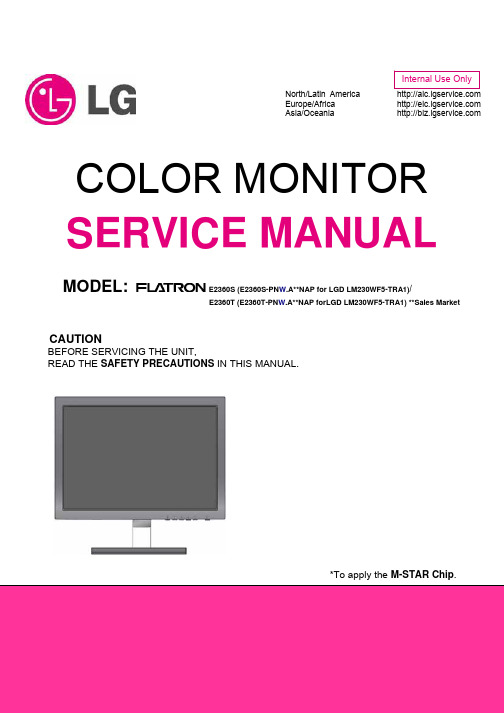
North/Latin America Europe/Africa Asia/Oceania COLOR MONITOR SERVICE MANUAL MODEL: E2360S (E2360S-PN W.A**NAP for LGD LM230WF5-TRA1)/E2360T (E2360T-PN W.A**NAP forLGD LM230WF5-TRA1) **Sales MarketCAUTIONBEFORE SERVICING THE UNIT,READ THE SAFETY PRECAUTIONS IN THIS MANUAL.*To apply the M-STAR Chip.Copyright © 2010 LG Electronics. Inc. All right reserved. - 2 - LGE Internal Use Only CONTENTSSPECIFICATIONS ..........................................................2 PRECAUTIONS ..............................................................3 TIMING CHART ..............................................................7 DISASSEMBLY .............................................................8 BLOCK DIAGRAM.........................................................10 DISCRIPTION OF BLOCK DIAGRAM . (12)ADJUSTMENT ............................................................. 13 SERVICE MODE ......................................................... 16 TROUBLESHOOTING GUIDE .................................... 17 WIRING DIAGRAM ...................................................... 23 EXPLODED VIEW........................................................ 24 SCHEMATIC DIAGRAM.. (26)SPECIFICATIONSE2360S&T1. LCD CHARACTERISTICS Type: Flat Panel Active matrix-TFT LCD Active Display Area: 23.0 inches/58.4 cmPixel Pitch: 0.265 mm x 0.265 mmSurface Treatment: Anti-Glare coating Resolution: Max: VESA 1920x1080@60Hz.Recommend: VESA 1920x1080@60Hz.Video Input:Signal Input: 15 pin D-Sub Connector; DVI-D Connector (Only for E2360T)Input Form: RGB Analog (0.7 Vp-p/75 ohm)Digital (Only for E2360T) Plug&Play: DDC2AB (Analog)DDC2B (Digital) (Only for E2360T)2. POWER SUPPLY 2-1. Power: 12V==3.0A2-2. Power Consumption On Mode: 30W (Typ.) Sleep Mode: ≤ 1 W Off Mode: ≤ 0.5 W3. Sync Input Horizontal Freq. 30 kHz to 83 kHz (Automatic)Vertical Freq. 56 Hz to 75 Hz (Automatic) Input Form Separate Sync.Digital (Only for E2360T)4. ENVIRONMENT4-1. OperatingTemperature: 10°C to 35°CHumidity: 10 % to 80% non-Condensing 4-2. StorageTemperature: -20°C to 60 °CHumidity: 5 % to 90 % non-Condensing5. DIMENSIONS (with Stand) Width 54.23 cm (21.35 inch) Height 41.20 cm (16.22 inch) Depth 17.20 cm (6.77 inch) DIMENSIONS (without Stand) Width 54.23 cm (21.35 inch) Height 40.83 cm (16.07 inch) Depth 3.10 cm (1.22 inch)6. WEIGHT (excl. packing) Weight: 2.6 kg (5.73 lb)Copyright © 2010 LG Electronics. Inc. All right reserved. - 3 - LGE Internal Use OnlyTIMING CHARTE2360S&TDisplay Modes (Resolution)Horizontal Freq. (kHz) Vertical Freq. (Hz)1 720 x 400 31.468 702 640 x 480 31.469 603 640 x 480 37.500 754 800 x 600 37.879 605 800 x 600 46.875 756 1024 x 76848.363 607 1024 x 76860.123 758 1152 x 86467.500 759 1280 x 102463.981 6010 1280 x 1024 79.976 7511 1680 x 1050 65.290 60*12 1920 x 1080 67.500 60*Recommend ModeDISASSEMBLY-Set#1Put the monitor on a soft flat. #2Remove the base ass’y.Turn the screw by using the screw handle. #3Remove the Rear Cover ass’y. #4The Rear Cover ass’y. #5Disconnect all the wires/FFC cable.#6Remove the main frame.#7Main frame and main board. #8The panel.Note: DVI only for E2360T.BLOCK DIAGRAMNote: DVI only for E2360T.CONVERTER BLOCK DIAGRAM ConverterDESCRIPTION OF BLOCK DIAGRAM1. Video Controller Part.This part amplifies the level of video signal for the digital conversion and converts from the analog video signal to the digital video signal using a pixel clock.The pixel clock for each mode is generated by the PLL.The range of the pixel clock is from 25MHz to 149MHz.This part consists of the Scalar, ADC converter, TMDS receiver.The Scalar gets the video signal converted analog to digital, interpolates input to 1920 x 1080 resolution signal and outputs 8-bit R, G, B signal to transmitter.2. Power Part.This part consists of the one 3.3V regulators to convert power which is provided 12V in Adapter board, 12V is provided for convert circuit.3. MICOM Part.This part is including video controller part. And this part consists of Reset IC and the Micom.The Micom distinguishes polarity and frequencies of the H/V sync are supplied from signal cable.The controlled data of each mode is stored in scalar.ADJUSTMENTWindows EDID V1.0 User ManualOperating System: DOS, windows98, 2000, XP1. Parallel port settingEnter your bios, and do as followings.a) Integrated peripheralb) Super IO Devicec) Parallel port modeyou should set the” parallel port mode” to SPP for using the DOS EDID tool surely.2. EDID Write1. Connect the signal line of monitor with DDC recorder.2. Choose the DDC RECORD program, and it shows on the screen, then choose the correct source base on the monitor.3. Click “LoadFile”, then key in the manufacturer name, model name, product code, then choose the correct model name base on the monitor.(as Fig.2)4. Scan serial No. to DDC recorder by Bar Reader, then read again in the Verify SN.5. According to the message of DDC program, when the picture as fig.1 appears, it will show DDC record has finished.E2360S (Analog only)Fig.1Please check Manufacturer Name, Vendor Assigned Code, Monitor Name, Serial Number:*****[????????*****] (it must be the same as Bar Code),Week of Manufacture:**,Year of Manufacture:****,Checksum:** (It must be the same as the last byte of data table, as follows picture shows). Above of all must be right, then if it shows the green “PASS”, it means record succeeds ,the red “Fail” means record fails; Then check the power supply and signal line, and ensure they are connected well ,then do DDC record again from the third step.E2360S (Analog only)Fig.2TROUBLESHOOTING GUIDE1. NO POWER2. NO RASTER (OSD IS NOT DISPLAY)-LIPS3. NO RASTER (OSD IS NOT DISPLAY)-MSTAR4. TROUBLE IN DPM5. POWER6. RASTERWIRING DIAGRAMNote: DVI only for E2360T.EXPLODED VIEW PARTS LISTRef. No. TPV part No.LGE part No.Description010 705GFACS016 ABJ73308504 BEZEL ASS'Y 020 KEPCAQG1 EBU60704503 KEY BOARD 030 LEPCAQG1EBU60934810LED BOARD040 750GMT230W5A11M0LG COV30101224 PANEL LM230WF5-TRA1-7F1-A0 FQ LTD 050756GQACB-KL010--00 EBU60714340 MAIN BOARD(CBPCAAWLGQ3)-E2360S 756GQACB-KL009--00EBU60714341 MAIN BOARD(CBPCAARLGQ3)-E2360T060Q15G0909101101 MDQ62638101MAINFRAME-E2360S Q15G0909101201 MDQ62638102 MAINFRAME-E2360T 070 705GFACS012 ACQ83873708 REAR COVER ASS'Y-E2360S 705GFACS013ACQ83873709 REAR COVER ASS'Y-E2360T 080 705GFACS004 ACQ83873802 BASE ASS'Y 090 095G176J-10V01 COV30101415 FFC CABLE 10PIN 275MM 0.5MM 100 095G176J-50528 COV30101418 FFC CABLE 50 182 0.5 110 095G8022-7W506 N/A HARNESS 7P-6P+3P 250/300 120088G-35315FVCLN/AD-SUB CABLE 1500MMSCHEMATIC DIAGRAM1. Main BoardE2360S&TInput (DVI only for E2360T)Copyright © 2010 LG Electronics. Inc. All right reserved. - 26 - LGE Internal Use Only5Copyright © 2010 LG Electronics. Inc. All right reserved. - 27 - LGE Internal Use OnlyCMVCC12,3,5Copyright © 2010 LG Electronics. Inc. All right reserved. - 28 - LGE Internal Use OnlyCopyright © 2010 LG Electronics. Inc. All right reserved. - 29 - LGE Internal Use OnlyCopyright © 2010 LG Electronics. Inc. All right reserved. - 30 - LGE Internal Use Only2. Key BoardCopyright © 2010 LG Electronics. Inc. All right reserved. - 31 - LGE Internal Use Only3. LED BoardCopyright © 2010 LG Electronics. Inc. All right reserved. - 32 - LGE Internal Use OnlyJul.2010 P/NO: Printed in China。
ViewSonic VA1916w LCD Display 说明书
ViewSonic®VA1916wLCD DisplayModel No. : VS12085内容TCO信息 (i)电磁相容信息 (1)重要的安全指示 (2)中国电子信息产品污染控制标识要求 (3)版权信息 (4)产品注册 (4)开始包装内容 (5)注意事项 (5)快速安装 (6)墙壁安装(可选) (7)使用LCD显示器设置定时模式 (8)菜单和电源按键锁定设置 (8)调整屏幕图像 (9)主菜单控件 (11)其它信息技术规格 (14)故障诊断 (15)客户支持 (16)如何清洁LCD显示器 (17)有限担保 (18)TCO 信息Congratulations!The display you have just purchased carries the TCO’03 Displayslabel. This means that your display is designed, manufactured andtested according to some of the strictest quality and environmentalrequirements in the world. This makes for a high performanceproduct, designed with the user in focus that also minimizes theimpact on our natural environment.Some of the features of the TCO’03 Display requirements:ErgonomicsGood visual ergonomics and image quality in order to improve the working environment for the user and to reduce sight and strain problems. Important parameters are luminance, contrast, resolution, reflectance, colour rendition and image stability.Energy•Energy-saving mode after a certain time - beneficial both for the user and the environment •Electrical safetyEmissions•Electromagnetic fields•Noise emissionsEcology•The product must be prepared for recycling and the manufacturer must have a certified environmental management system such as EMAS or ISO 14000•Restrictions ona.chlorinated and brominated flame retardants and polymersb.heavy metals such as cadmium, mercury and lead.The requirements included in this label have been developed by TCO Development in co-operation with scientists, experts, users as well as manufacturers all over the world. Since the end of the 1980s TCO has been involved in influencing the development of IT equipment in a more user-friendly direction. Our labelling system started with displays in 1992 and is now requested by users and IT-manufacturers all over the world.For more information, please visit电磁相容信息FCC声明本设备符合 FCC 规则第 15 部分的规定。
笔记本电脑维修手册
笔记本电脑维修手册笔记本故障维修判断指导作为一名笔记本电脑维修工程师,不仅要对笔记本电脑的硬件、软件及笔记本电脑的结构有较全面的了解,而且还要掌握一定的维修理论与维修方法。
联想昭阳笔记本测试项目针对目前维修工程师在维修中工具和维修测试比较缺乏的现状,在技术支持处的努力下及多方面的配合,完成了昭阳笔记本电脑功能测试这个项目,在这个功能测试项目中包含了联想昭阳2001年自今的14款机型的功能测试,希望能对联想维修服务有所支持。
下面将先就维修中的有关操作及维修方法进行一些探讨,对有关问题进行一些总结。
第一节笔记本电脑维修介绍在电脑维修中,根据维修对象的不同,可分为如下的三个级别:一级维修,也叫板级维修。
其维修对象是电脑中某一设备或某一部件,如主板、电源、显示器等,而且还包括电脑软件的设置。
在这一级别,其维修方法主要是通过简单的操作(如替换、调试等等),来定位故障部件或设备,并予以排除。
例如:有一台电脑开机后无任何显示。
作为一级维修,需要判断出此现象是由于显示器的原因引起的,还是显示卡的原因引起的,甚或是主板的原因引起的,只要判断出引起故障的部件,并更换掉有故障的部件,即完成维修任务。
二级维修,是一种对元、器件的维修。
它是通过一些必要的手段(如测试仪器)来定位部件或设备中的有故障的元件、器件,从而达到排除故障的目的。
例如:在上一例中,如果是二级维修,就不仅要判断出是哪个部件,还要判断出是该部件上的哪一个器件或元件出现故障,并修复有故障的元器件,才算完成维修任务。
三级维修,也叫线路维修,顾明思意,就是针对电路板上的故障进行维修。
还是上例,如果是线路设计或线路故障引起无显示,就需要三级维修人员来维修。
这些人往往是系统的设计开发人员。
从这三个级别的维修内容来看,高一级的维修必然要包含着低一级的维修,且一级维修是所有级别维修的基础。
需要进行三级维修的电脑故障是很少很少的,最多的是二级维修和一级维修。
但在电脑行业中,由于电脑部件的成本的不断降低,再加上一级维修的成本也很低,因此一级维修的地位变得越来越重要,在现在的电脑维修中,主要采用的是一级维修。
液晶电视维修手册(pdf 84页)

主板 (小信号处理+逻辑驱动)
第二节 主板组件速判速修
1、LS08机芯(TDA15063 + GM1501方案)
派生系列 W***F8系列 W***F8P系列 TD***F8系列 18系列 18P系列 20系列
代表机型 CHD-W260F8、CHD-W270F8、CHD-W320F8、CHD-W370F8 CHD-W270F8P、CHD-W320F8P、CHD-W370F8P CHD-TD270F8、CHD-TD320F8、CHD-TD370F8 LT2618、LT3218、LT3718、LT4018、LT4219B LT3718P、LT4018P LT5520
2、LP09机芯(PW328 + PW2300方案)
派生系列 19/20系列 19P/19H/66系列 99系列 33系列
代表机型 LT4219、LT4619、LT3718H、LT4720H LT4719H、LT4219P、LT4619P、LT4266、 LT4219H LT4099、LT4299、LT4699 LT4233
LS08机芯技改方案
1. F8/18系列音量关小,有交流噪音。 解决方案:将主板功放电路位号为RA8在主板背面(15K)的电阻改为 10K或8.2K。改后若整体音量变小,请对TDA15063进行升级,以提高 TDA15063输出的伴音信号的幅度。
2. 37〞~42〞F8/18 系列电源板出现噪音 解决方案:取消自制GP03开关电源中U810、L810、D818。
目录
一、液晶电视的结构及各组件控制关系: 二、长虹液晶电视主板组件的快速识别: 三、OEM产品的快速识别和判定: 四、屏上组件的识别和判定: 五、二合一电源组件组件的识别和判定: 六、技术资料的查询和替换:
液晶显示器维修手册
液晶显示器维修手册第一章: 引言液晶显示器维修手册是为了帮助用户了解液晶显示器的维修和故障排除方法而编写的。
本手册将提供液晶显示器常见问题的解决方案和处理方法,以确保用户能够迅速恢复屏幕的正常运行。
第二章: 基础知识在进行液晶显示器维修之前,用户需要了解一些基础知识。
液晶显示器是通过液晶技术显示图像的设备。
它是由像素组成的,每个像素都由液晶层和光源背光组成。
用户需要熟悉液晶显示器的组成部分、原理和常见故障类型。
2.1 液晶显示器的组成部分液晶显示器由多个组件组成,包括面板、背光源、控制电路、接口等。
用户需要了解这些组件的功能和相互关系。
2.2 液晶显示器的工作原理液晶显示器的工作原理包括电压控制液晶颗粒来控制光的通过、背光源的照明方式以及图像传输的过程。
用户需要熟悉这些原理,以便更好地进行维修工作。
2.3 常见故障类型液晶显示器常见故障类型包括无法开机、黑屏、色彩失真、图像闪烁等。
用户需要了解每种故障类型的原因和相应的维修方法。
第三章: 维修步骤本章将详细介绍用户在维修液晶显示器时需要采取的步骤。
3.1 故障诊断在开始维修前,用户需要先进行故障诊断。
通过观察、测试和排除法等方法,找出故障产生的原因。
3.2 维修工具和材料准备用户需要准备一些常用的维修工具和材料,如螺丝刀、电压表、焊接工具等。
这些工具和材料在维修过程中起到关键作用。
3.3 维修操作步骤在进行维修操作时,用户需要按照以下步骤进行:1) 关闭电源并拔掉电源线;2) 拆卸外壳以获得维修接触面;3) 检查电源问题,如电源线是否损坏或电源板是否故障;4) 检查信号线或接口问题,确保连接良好;5) 检查背光源是否正常运行;6) 检查控制电路和面板问题;7) 清洁显示屏和其他组件;8) 重新组装并测试修复效果。
第四章: 常见故障与解决方案本章将列举液晶显示器常见的故障情况,并提供相应的解决方案。
4.1 无法开机当液晶显示器无法开机时,可能是由于电源故障、信号线松动或电源线接触不良等原因造成。
AOC 919Sw维修手册
维修手册客户 机种名 销售地区AOC 919Sw 中国大陆T98VRDNDWKA4NNET99HRDNDWKA4NNE首次发布日期: 04/2009目录1.安全与注意事项------------------------------------------------------------------------------------------------------032.技术规格---------------------------------------------------------------------------------------------------------------053.操作说明及工厂模式调整------------------------------------------------------------------------------------------084. ISP升级流程---------------------------------------------------------------------------------------------------------125.故障处理流程---------------------------------------------------------------------------------------------------------156.电气方框图------------------------------------------------------------------------------------------------------------197. PCB分布图-----------------------------------------------------------------------------------------------------------208.线路图------------------------------------------------------------------------------------------------------------------259.爆炸图------------------------------------------------------------------------------------------------------------------3310. BOM------------------------------------------------------------------------------------------------------------------3411. BOM差异比较-----------------------------------------------------------------------------------------------------421.安全与注意事项FCC 注意事项FCC B 类无线电频率干扰声明警告:(对于 FCC 认证的型号)注意:本设备已经通过测试,符合 FCC 规定第 15 部分有关 B 类数字设备的限制。
电子产品维修手册

电子产品维修手册一、前言电子产品已经成为现代生活中不可或缺的一部分。
然而,由于各种原因,这些产品在使用过程中可能会出现各种故障。
为了帮助用户解决一些常见的问题,本手册将提供一些关于电子产品维修的基本知识和技巧。
二、安全注意事项1. 在进行任何维修工作之前,务必断开电源,并确保设备完全停止工作。
2. 佩戴适当的防护装备,如手套和护目镜,以防止意外受伤。
3. 谨慎处理易碎件和敏感元件,避免损坏或静电放电。
4. 如果您对任何维修步骤不确定,请咨询专业人士或联系厂家客户支持。
三、故障排除1. 电源问题- 确保电源插头已正确插入插座。
- 检查电源线是否损坏,如有损坏应更换。
- 在尝试其他解决方案之前,重启设备可能有助于解决电源问题。
2. 屏幕问题- 如果屏幕没有显示任何图像,首先检查连接电缆是否牢固。
- 调整屏幕亮度和对比度设置,以确保其工作正常。
- 如果屏幕有黑屏或闪烁问题,可能需要更换屏幕或接触厂家客户支持。
3. 硬件问题- 对于电脑或手机等设备,如果发现运行缓慢或者出现卡顿现象,可以尝试清理存储空间或重启设备。
- 如果硬件组件(如键盘、鼠标)损坏,可能需要进行部件更换或者修复。
四、常见问题解答问题1:手机无法开机解决方案:尝试长按电源键并保持5秒钟,如果不起作用,请充电然后再次尝试。
问题2:电脑蓝屏解决方案:重启电脑,如果问题仍然存在,根据蓝屏错误代码查询相关解决方案或联系厂家技术支持。
问题3:电视遥控器无法正常工作解决方案:检查遥控器电池是否耗尽,如果是,请更换新电池。
确保遥控器与电视之间没有障碍物,并且在正确的范围内使用。
问题4:音响无声解决方案:检查音响与音频源的连接,确保线缆连接正确。
调整音响音量控制器或检查音频输出设置,也确保音频源本身没有问题。
五、维修保养建议1. 定期清洁设备,避免尘埃积聚影响正常工作。
2. 避免将设备暴露在极端温度或湿度环境下,以免损坏内部部件。
3. 减少设备的震动和冲击,以防止部件松动或断裂。
冠捷液晶显示器维修教程
部分己经短路(出现“亮点”),或者断路(出现“黑点”)。有些顾客可能认为如此高
昂的价格应该买到完美的LCD显示屏-很不幸这不是现实,最多能挑到暇点不特别明
显的屏幕而已。
8
•
LCD显示屏包含了在CRT技术中未曾用到的一些东西。为屏幕提供光源的是盘绕
在其背后的荧光管。有些时候,我们会发现屏幕的某一部分出现异常亮的线条。也
D
CLC
G
com
7
LCD技术缺陷
•
规则LCD遵守一系列与CRT显示不同的规则。LCD克服了CRT体积庞大、耗电和
闪烁的缺点,但也同时带来了造价过高、视角不广以及彩色显示不理想等问题。CRT
显示可选择一系列分辨率,而且能按屏幕要求加以调整,但LCD屏只含有固定数量的
液晶单元,只能在全屏幕使用一种分辨率显示(每个单元就是一个像素)。CRT通常有
三个电子枪,射出的电子流必须精确聚集,否则就得不到清晰的图像显示。但LCD不
存在聚焦问题,因为每个液晶单元都是单独开关的。这正是同样一幅图在LCD屏幕上
为什么如此清晰的原因。LCD也不必关心刷新频率和闪烁,液晶单元要么开,要么关,
所以在40-60Hz这样的低刷新频率下显示的图像不会比75Hz下显示的图像更闪烁。
(0603)
R921 C911
683 222
(0805) (0805)
R924
R925
103
1K
(0603)
7 8
6 4 IC901
56A379 -12
1 3
2 5
R905 R906 R907
C905
304
304 304
1500
(1206) (1206) (1206)
理光1610l维修手册p3
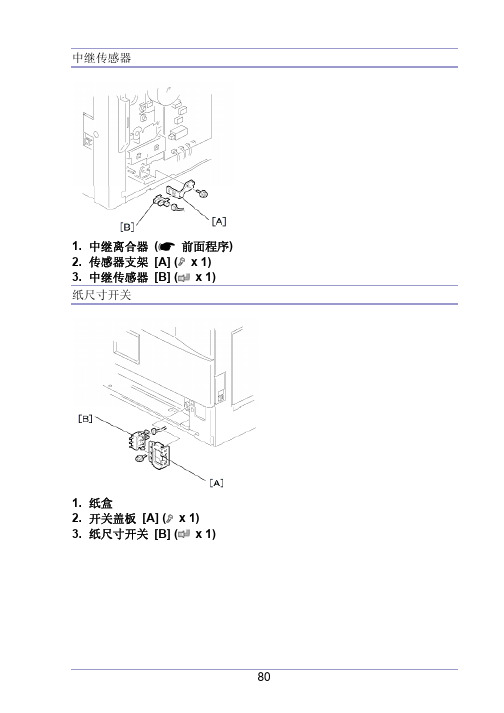
中继传感器1. 中继离合器(前面程序)2. 传感器支架 [A] ( x 1)3. 中继传感器 [B] ( x 1)纸尺寸开关1. 纸盒2. 开关盖板 [A] ( x 1)3. 纸尺寸开关 [B] ( x 1)图像转印图像转印辊不要用裸手碰转印辊的表面。
1. 打开右门。
2. 和图像转印辊 [B] 一起提升塑料架子 [A]。
让弹簧留在架子的下面,确信重新组装时,架子 [D] 上的栓子 [D] 啮合了弹簧。
图像浓度传感器1. 打开右门。
2. 塑料盖板 [A]3. 图像转印辊(前面程序)4. 下按槽口 [B] 以释放传感器。
5. 图像浓度传感器 [C] ( x 1)定影单元定影单元会变得很烫,传递前确信它已冷却。
1. 关闭主开关,拔掉机器插头。
2. 前右盖板3. 打开右门。
4. 定影单元[A] ( x 2, x 4)热敏电阻1. 定影单元(见上面)2. 热敏电阻 [A] ( x 1, x 1)2. 分离热辊部分 [A] 和压辊部分 [B] ( x 4).3. 前固定板 [C] ( x 1)4. 后固定板 [D] ( x 1)5. 有接头的定影灯 (600 W) [E] ( x 2)6. 有接头的定影灯 (550 W) [F] ( x 2)列不正确,就放不好它们。
热辊分离爪1. 热辊部分(见上面)2. 辊子防护板 [A] ( x 3)3. 金属架 [B] (各1个架)4. 热辊分离爪 [C] (各1根弹簧)热辊1. 热辊分离爪(见上面)2. 热辊 [A] (2个C-圈, 1个齿轮, 2个轴衬)恒温器1. 热辊(见上面)2. 恒温器 [A] ( x 各2个)压辊和轴衬1. 分开热辊部分和压辊部分(定影灯)2. 定影入口导板[A] ( x 2)3. 2根弹簧[B]4. 2个压力作动臂[C]5. 2个轴衬[D]6. 压辊 [E]轧带宽度调整定影温度在工作温度上时执行这个调整。
必须用A4 / LT纵送OHP纸,其它纸可能产生卡纸。
acer显示器怎么维修
acer显示器怎么维修在有些时候我们的acer显示器出现故障了这该怎么维修呢?下面就由店铺来为你们简单的介绍acer显示器的维修方法吧!希望能帮到你们哦!acer显示器的故障维修方法:故障一:acer液晶显示器电源灯亮着,但屏幕上没有显示。
我们先来分析一下,显示器的电源灯还会正常亮起说明电源与显示器之间的电源是没有问题的,那就很容易断定是显示器电源与屏幕之间出现了接触不良或短路。
知道了原因就好办了,我们将显示器的外壳拆下,会看到两个控制电路和电源电路的电路板,我们将其拆下后会看到显示面板的x、y正负两极的数据线,我们将测试仪器与这两段接通即可开始检测,是那一段的电路出现了问题。
故障二:acer液晶显示器的显示画面紊乱且不稳定,有雪花、跳屏现象出现。
这种情况的出现一般有两种情况,第一种是电压输入不稳,显示器工作环境达不到相应要求。
第二种是显示器受到了的外部磁场的干扰,导致显示效果受损。
这两种情况都不是很严重,第二种甚至都不需要去维修,只要将电脑旁边的东西拿掉就可以了。
区分也很简单,我们只要将显示器放到另一个房间看看显示效果怎么样就可以了。
如果是第一种情况,小编建议您还是去专业的维修点去修,以免出现问题。
附加电脑显示器常见故障维修分析:显示屏黑屏,无背光.电源灯绿灯常亮.斜视液晶屏有显示图像,多属于高压板供电电路问题.重点检查12V供电(保险丝F)和3V或5V的开关电压是否正常.若是因为MCU问题造成没有输出开关控制电压,可以直接提取3端稳压块的(AIC1084)3.3V代替.修理高压板的思路(电源保险丝----开关控制管----电源管理IC--推挽发大管----电源开关管----DA转换电路(储能电感,整流管)---LC升压电路(升压变压器,升压电容)---耦合电容----灯管.屏幕亮线,亮带或者是暗线这种问题,一般是液晶屏的故障。
亮线故障一般是连接液晶屏本体的排线出了问题或者某行和列的驱动IC损坏。
电视机背光维修技术手册
电视机背光维修技术手册随着智能电视的普及,电视机背光逐渐成为了家电维修的一个重要环节。
正常的背光是保证电视机画面亮度和色彩的关键因素,一旦背光出现问题,那么整个画面质量就会受到影响。
本手册将深入解析电视机背光的构成和不同故障情况,提供详细的维修技术指南,帮助电视机维修人员迅速准确地判断背光故障,并快速进行修复。
第一章背光的构成电视机背光是指通过灯条或灯珠等背光源,在液晶显示面板背面照射,起到增加亮度、改善色彩饱和度的作用。
常见的背光分为CCFL 和LED两种。
CCFL(冷阴极荧光灯)是一种旧式的背光源,由于其亮度较低且寿命短,在2012年之后逐渐被LED所替代,目前已经基本淘汰。
LED背光源是一种新型的背光技术,它具有亮度高、寿命长、功耗低等优点,因此被广泛应用于各种类型的电视机中。
第二章背光常见故障电视机背光故障的原因一般有以下几种:1.灯头与灯座之间接触不良2.背光柜厂家生产的工艺和经验不足导致质量问题3.LED灯簇故障4.电源板输出电压稳定性问题在检测背光故障时,可以通过以下几点来判断:1.打开电视机时,屏幕背景亮度较暗,不均匀。
可能存在一个或多个灯块坏掉的问题。
2.打开电视机时,背景亮度明显较暗。
此时,可能会出现LED灯珠故障或电源板输出电压稳定性差的问题。
3.打开电视机时,背光亮度明显不一。
此时,可能会出现几个灯块的亮度不一致问题,或者是一个或多个LED灯簇损坏的问题。
第三章背光维修技术当发现电视机存在背光故障时,我们需要准确快速地进行检修,以下是背光维修的技术指南:1.检测LED灯簇是否故障,通过万用表或者电压表检测单个LED灯簇的电流是否正常。
如果异常,则需要更换灯簇。
2.检测LED灯簇与散热器之间的导热硅脂,如果发现干裂老化,则需要重新涂覆导热硅脂。
3.检测灯头和灯座之间的接触,如果发现接触不良,则需要重新插拔。
4.检测电源板的输出电压稳定性,如果不稳定,则需要更换电源板。
需要注意的是,进行背光维修时需要非常谨慎,在拆装电视机或更换元器件时需要注意安全。
2008年冬季培训资料-台式机常见问题及解决方案

Aspire SA80/AcerPower S280风扇噪音大•问题描述:客户反映Aspire SA80/AcerPower S280风扇噪音大。
•原因分析:由于BIOS版本太原分析本低造成。
•解决方案:将BIOS升级到R01-C3版可解决此问题。
Aspire SA70分辩率设置问题i分辩率设置问题1.问题描述:客户反映AspireSA70在使用AL1916W LCD显示器时,不能将分辩率设置为1440*900的宽屏显示模式。
2.原因分析:由于BIOS版本太低造成。
3.解决方案:将主板BIOS版本刷新到R01-A0S1可以解决。
到R01A0S1可以解决。
Aspire M3600/M5600更换主板后i更换主板后1.问题描述:Aspire M3600/M5600 维修更换主板以后,Vista操作系统需要激活。
激活2.原因分析:在VISTA系统,OEM采用SLP2.0的验证机制,如果条件具备,SLP20的验证机制如果条件具备则VISTA OEM系统为免激活,否则等同零售版,须在天内激活更同于零售版,必须在30天内激活。
更换的备件主板BIOS里可能不含有该品牌的OEM KEY的数字签名或不含有该品牌的OEM授权证书的数字签名品牌的OEM授权证书的数字签名。
3.解决方案:更新BIOS至R01-A3。
AG1720 AG1720/AG3720开机风扇常转1.问题描述:AG1720/AG3720开机风扇常转,不能自动降速。
2.原因分析:由于BIOS版本太低造成。
成3.解决方案:AG1720/AG3720主板跟PG4600通用,可以用PG4600解决风扇常转问题BIOS刷新解决。
AG1720随机光盘VGA驱动不能使用1.问题描述:AG1720随机光盘VGA驱动不能使用。
2.原因分析:由于随机光盘VGA驱动版本太低造成。
3.解决方案:从Acer网站下载更新的VGA驱动可以正常安装。
AcerPower S210/Aspire SA10反复重起死机1.问题描述:Power S210/AspireSA10台式机出现反复重起死机SA10台式机出现反复重起死机。
宏基 Table of Contents LCD MONITOR 说明书

Table of Contents Preface (2)Chapter 1 Installation (4)Unpacking (4)Connecting the LCD Monitor and Base (4)Viewing Angle Adjustment (4)Detaching LCD Monitor from Its Stand (5)Interface for Arm Applications (5)Connecting the Display to your Computer (5)Connecting the AC Power (7)Setting Up the LCD Monitor (7)Power Management System (7)Chapter 2 Display Controls (8)User Controls (8)Adjusting the Monitor's Display (8)Function Description (10)Chapter 3 Technical Information (12)Specifications (12)Standard Timing Table (15)Troubleshooting (17)2PrefaceThis manual is designed to assist users in setting up and using the LCD Monitor. Information in this document has been carefully checked for accuracy; however, no guarantee is given to the correctness of the contents. The information in this document is subject to change without notice. This document contains proprietary information protected by copyright. All rights are reserved. No part of this manual may be reproduced by any mechanical, electronic or other means, in any form, without prior written permission of the manufacturer.FCC Statement WarningThis equipment has been tested and found to comply with the limits for a Class B digital device, pursuant to Part 15 of the FCC Rules. These limits are designed to provide reasonable protection against harmful interference in a residential installation. This equipment generates, uses, and can radiate radio frequency energy, and if not installed and used in accordance with the instruction, may cause harmful interference to radio communications. However, there is no guarantee that interference will not occur in a particular installation. If this equipment does cause harmful interference to radio or television reception, which can be determined by turning the equipment off and on, the user is encouraged to try to correct the interference by one or more of the following measures:• Reorient or relocate the receiving antenna.• Increase the separation between the equipment and the receiver.• Connect the equipment into an outlet on a circuit different from that to which the receiver is connected.• Consult the dealer or an experienced radio/TV technician for help.Any changes or modifications not expressly approved by the manufacturers may void the user's authority to operate this equipment.NOTEA shielded-type signal cord is required in order to meet the FCC emission limits and also to prevent interference to the radio and television reception. It is essential that only the supplied signal cord be used.Canadian DOC Notice3This Class B digital apparatus meets all requirements of the Canadian Interference-Causing Equipment Regulations.Cet appareil numérique de la classe B repecte toutes les exigences du Règlement sur le matériel brouilleur du Canada.Important Safety InstructionsPlease read the following instructions carefully. This manual should be retained for future use. 1. To clean LCD Monitor screen;-- Power off LCD Monitor and unplug the AC Cord.-- Spray a non-solvent cleaning solution onto a rag.-- Gently clean the screen with dampened rag.2. Do not place the LCD Monitor near a window. Exposing the monitor to rain water, moisture or sunlight can severely damage it.3. Do not apply pressure to the LCD screen. Excess pressure may cause permanent damage to the display.4. Do not remove the cover or attempt to service this unit b y yourself. Servicing of any nature should be performed by an authorized technician.5. Store LCD Monitor in a room with a room temperature of -20° ~ 60°C (or -4° ~ 140°F). Storing the LCD Monitor outside this range could result in permanent damage.6. If any of the following occurs, immediately unplug your monitor and call an authorized technician.* Monitor to PC signal cable is frayed or damaged.* Liquid spilled into LCD Monitor or the monitor has been exposed to rain.* LCD Monitor or the case is damaged.7. A certified line is required to connect this device to a power outlet. For a nominal current up to 6A and a device weight above 3 kg, a line not lighter than H05VV-F, 3G, 0.75 mm 2 must be used. 8. For use only with power supply type: Li-shin, LSE 9802A12404Chapter 1 InstallationUnpackingBefore unpacking the LCD Monitor, prepare a suitable workspace for your Monitor and computer. You need a stable and clean surface near a wall power outlet. Make sure that LCD Monitor has enough space around it for s ufficient airflow. Though the LCD Monitor uses very little power, some ventilation is needed to ensure that the Monitor does not become too hot.After you unpack the LCD Monitor, make sure that the following items were included in the box:* LCD Monitor * AC Adapter* 1.5M Monitor-to-PC signal Cable * 1.8M Power Cord* User's Manual * BaseIf you find that any of these items is missing or appears damaged, contact your dealer immediately.When you open the box to take the baseand put on the desk first. Then connectthe LCD Monitor and base please.(Seefig.1-1 )Viewing Angle AdjustmentThe LCD Monitor is designed to allowusers to have a comfortable viewingangle. The viewing angle can be adjustedfrom -5°t o +35°.(See fig. 1-2)WarningDo not force the LCD Monitor over its maximum viewing angle settings as stated above. Attempting this will result in damaging the Monitor and Monitor stand.5Detaching LCD Monitor from Its Stand1.2. Remove the standfrom LCD monitor(See fig. 1-3)Interface for Arm ApplicationsBefore installing to mounting device, please referto Fig.1-3.The rear of this LCD display has four integrated4 mm, 0.7 pitches threaded nuts, as well as four5 mm access holes in the plastic covering asillustrated in Figure 1-4. These specificationsmeet the VESA Flat Panel Monitor PhysicalMounting Interface Standard (paragraphs 2.1and 2.1.3, version 1, dated 13 November 1997).Figure 1-4Connecting the Display to your Computer1. Power off your computer.2.LCD Monitor's VGA port. (See Fig. 1-5)3. the VGA port on your PC.4. Make sure both connections are secure.Figure 1-5AttentionThis device must be connected to an off-the-shelf video cable in order to comply with FCC regulations. A ferrite-core interface cable is included in the LCD Monitor package.This device will not be in compliance with FCC regulations when a non-ferrite-core video cable is6used.7Connecting the AC Power1. Connect the power cord to the AC adapter.(See Fig. 1-6)2. Connect the AC adapter's DC outputconnector to the DC Power Jack of themonitor.3. Connect the power cord to an AC powersource.Figure 1-6WarningWe recommand to install a "Surge Protector" device between the AC Adapter and the electrical wall outlet for adding protection against power surges to prevent the effects of sudden voltage variations from reaching the LCD Monitor. Sudden power surges may damage your monitor.Setting Up the LCD Monitor1. Make sure the AC Adapter is connected to the LCD Monitor.2. Turn on the LCD Monitor's power switch, located on the bezel of the monitor.Power Management SystemThis LCD Monitor complies with the VESA DPMS (version 1.0) Power Management guidelines. The VESA DPMS provides four power saving modes through detecting a horizontal or vertical sync. signal.When the LCD Monitor is in power saving mode, the monitor screen will be blank and the power LED indicator will light yellow.8Chapter 2 Display ControlsUser ControlsA brief description and the location of all LCD Monitor function controls and indicators:Figure 2-1 1 DC Power Switch Press the power switch to switch the monitor ON/OFF.2 DC Power-OnIndicator LED lights Green color --- Power is ON.LED lights Yellow --- Monitor is in "Power Saving Mode".LED is off --- Power is OFF.3 Function Select Buttons Press either left or right control button for OSD (On Screen Display) menu selection.4 Adjustment Control Buttons Press the left button to decrease the OSD setting and press the right button to increase the OSD setting.Adjusting the Monitor's DisplayThe monitor has four function control buttons to select among functions shown on OSD menu, designed for easy user-viewing environments.OSD Function MenuTo access OSD Main menu, simply pressone of the Function Select control buttons,and the menu diagram will pop up on thescreen as shown on Fig. 2-2:Continue pressing the Function Selectbuttons to scroll through the entire menuitems ,then press Adjustment Controlbuttons to adjust content of selected item.Figure 2-2AttentionFirmware revision may have been updated into a latest version while the version number shown on9all OSD menus in this manual will stay as Ver. 1.00.10Function DescriptionIcon Function Description 9300 CIE coordinated Color Temperature of 9300°K Sets the CIE coordinate colortemperature to 9300°K6500 CIE coordinated Color Temperature of 6500°K Sets the CIE coordinate colortemperature to 6500°K11User Three colors (Red, Green, Blue) can be adjusted from the OSD menu Sets the settings to a by user definedCIE Temperature.12Chapter 3 Technical InformationSpecifications LCD Panel Hannstar AUSize 15.0" (38 cm) 15.0" (38 cm)Display Type Active matrix color TFT LCD Active matrix color TFT LCD Resolution 1024 x 768 1024 x 768Display Dot 1024 x (RGB) x 768 1024 x (RGB) x 768Display Area (mm) 304 x 228 (H x V) 304 x 228 (H x V)Display Color 262K 262KBrightness 200 cd/m 2 (typical) 200 cd/m 2 (typical)Contrast Ratio 300: 1 (typical) 350: 1 (typical)Response Time (15 + 35) ms (typical) 30 ms (Tr+Tf) (typical)Lamp Voltage 640 Vrms (typical) 630 Vrms (typical)Lamp Current 6.0 mA rms. (typical) 6.5 mA rms. (typical)Viewing Angle Vertical: -45° ~ +40° Horizontal: -60° ~ +60° Vertical: -60° ~ +40°Horizontal: -60° ~ +60°Display Colors 16.7M with FRC or DitheringVideoInput Signal Input Impedance Polarity Amplitude Multi-mode Supported Analog RGB 0.7Vp -p75 Ohm ± 2%Positive0 - 0.7 ± 0.05 VpHorizontal Frequency: 24 ~ 61 KHzVertical Frequency: 56 ~ 75 HzControlPower On/Off switch with LED indicatorOSDBrightness Contrast Horizontal Position Vertical Position Phase Clock Display Mode Setup DigitalDigitalDigitalDigitalDigitalDigitalUse EEPROM to save settings in memory13OSD Format 20 characters x 9 rows14Power Management Mode PowerAC Input LED ColorOn 25W maximum 240 VAC GreenStandby 5W maximum 240 VAC YellowSuspend 5W maximum 240 VAC YellowOff 5W maximum 240 VAC YellowDC Power Off 5W maximum 240 VAC DarkDisconnected 5W maximum 240 VAC Yellow: Standby, Suspend, OffDark: DC Power off* Meeting VESA DPMS requirements measured from AC Input end of AC adapter.Sync InputSignal Separate TTL compatible horizontal and vertical synchronization Polarity Positive and negativePlug & Play Supports VESA DDC1 and DDC2B functionsExternal ConnectionPower Input (DC input) +12 VDC / 2.5A min. input through AC/DC adapterVideo Cable 1.5M with 15-pin D-sub connectorEnvironmentOperating Condition:Temperature 5°C to 40°C/41°F to 104°FRelative Humidity 20% to 80%Storage Condition:Temperature -20°C to 60° C/-4°F to140° FRelative Humidity 5% to 85%Power Supply (AC Adapter)Input Voltage Single phase, 100 ~ 240VAC, 50 / 60 HzInput Current 1.5 A maximumSize and WeightDimensions 349.6 (W) x 371.5 (H) x 158 (D) mm15Net Weight 3.2 ± 0.3 kgGross Weight 4.7 ± 0.3 kg Pin AssignmentStandard Timing TableIf the selected timing is NOT included in table below, this LCD monitor will use the most suitable available timing.Resolution H. Freq. (KHz) V. Freq. (Hz) Pixel Freq. (MHz) H/V Sync.Polarity Mode640 x 350 31.469 70.087 25.175 +/- VGA-350640 x 400 24.830 56.420 21.050 -/- NEC PC9801 640 x 400 31.469 70.087 25.175 -/+,-/- VGA-400-GRAPHNEC PC9821640 x 480 31.469 59.940 25.175 -/- VGA-480640 x 480 37.861 72.809 31.500 -/- VESA - 480 - 72Hz 640 x 480 37.500 75.000 31.500 -/- VESA - 480 - 75Hz 720 x 400 31.469 70.087 28.322 -/+ VESA-400-TEXT 800 x 600 35.156 56.250 36.000 +/+ SVGA800 x 600 37.879 60.317 40.000 +/+ VESA-600-60 Hz 800 x 600 48.077 72.188 50.000 +/+ VESA-600-72 Hz 800 x 600 46.875 75.000 49.500 +/+ VESA-600-75 Hz 832 x 624 49.725 74.55 57.2832 -/- APPLE MAC-800 1024x 768 48.363 60.004 65.000 -/- XGA161024x 768 53.964 66.13271.664 +/+ COMPAQ-XGA 1024x 768 56.476 70.06975.000 -/- VESA-768-70 Hz 1024x 768 60.023 75.02978.750 +/+ VESA-768-75 Hz17TroubleshootingThis LCD Monitor has pre-adjusted using factory standard VGA timings. Due to the output timing differences among various VGA cards in the market, users may initially experience an unstable or unclear display whenever a new display mode or new VGA card is selected.AttentionThis LCD Monitor Supports Multiple VGA Modes.Refer to the Standard Timing Table for a listing of modes supported by this LCD Monitor.The picture is unclear and unstable, please perform the following steps :1. Enter PC to “Shut Down Windows” status while you’re in MS -Windows environment.2. Check the screen to see if there’s any black vertical stripes appear. If there are, take advantage of the “Clock” function in OSD menu and adjust (by increment or decrement numbers) until those bars disappear.3. Move to “Phase” function in OSD menu again and adjust the monitor screen to its most clear display.4. Click “No” on “Shut Down Windows” and back to the normal PC operating environment.If there’s no picture on the LCD Monitor, please perform the following steps:1. Make sure the power indicator on the LCD Monitor is ON, all connections are secured, and the system is running on the correct timing. Refer to Chapter 3 for information on timing.2. Turn off the LCD Monitor and then turn it back on again. If there is still no picture, press the Adjustment Control button several times.3. If step 2 doesn’t work, connect your PC system to another external CRT. If your PC system Functions properly with a CRT Monitor but it does not function with the LCD Monitor, the output timing of the VGA card may be out of the LCD’s synchronous range. Please change to an alternative mode listed in the Standard Timing Table or replace the VGA card, and then repeat steps 1 and 2.If you have chosen an output timing that is outside of the LCD Monitor’s synchronous range (Horizontal: 24 ~ 61 KHz and Vertical: 56 ~ 75 Hz), the OSD will display a “Out of Range ” message. Choose a mode that is supported by your LCD Monitor.Also, if the signal cable is not connected to LCD monitor at all or properly, the monitor screen will display a message “No Input Signal ”.。
