交互式触摸显示器用户使用手册
HMI使用手册
第二章 机械设计参考������������������������ 12
2.1 安装环境注意事项����������������������������������� 12 2.2 安装方式��������������������������������������� 12 2.3 IT5000安装尺寸图����������������������������������� 14
机械环境
2.2 安装方式
InoTouch系列产品支持两种安装方式:一种是按照NEMA 4标准安装,采用本安装模式时,建议用户板金件按建议开 口尺寸开口,并使用附送的四个固定栓把本机紧固于用户板金面板中;另一种是VESA标准安装,采用本安装模式时,请 使用四个M4螺丝把本机固定于用户的安装支架上。(注:IT5043T不支持VESA标准安装。)
-8-
InoTouch系列人机界面用户手册
产品规格 型 号 IT5043T IT5070T IT5070E 可以 32bit RISC 400~800MHz 128MB 64MB DDRⅡ 256KB / / √ / COM1(RS422/ RS485),COM2 (RS232),COM3 (RS485) / / √ / √ √ / √ √ √ √ √ √ √ / √ √ √ √ √ √ √ √ IT5100T IT5104E
第五章 试运行、维护保养���������������������� 30
5.1 装机、保养时的注意事项�������������������������������� 30 5.2 上电前的检查������������������������������������� 30 5.3 上电运行操作������������������������������������� 31 5.4 维护����������������������������������������� 31
Anytouch WTM 系列触摸显示器用户手册说明书

触摸显示器用户手册TOUCH MONITOR USER’S MANUAL(适用型号:WTM系列)(Applicable models: WTM Series)版本:2014修订版A重要请仔细阅读用户手册,掌握如何安全、有效地使用本产品。
尽管本公司已经尽最大努力使本手册提供最新信息,但是请注意本公司显示器规格仍会未经通知即进行变更,恕不另目录第1章 介绍 2 第2章 安装 3 第3章 装配 6 第4章 操作7 第5章 技术支持10 第6章 安全与维护11 第7章 联系我们13产品说明新的触摸显示器集anytouch触摸产品的可靠性能和触摸技术与显示屏设计领域的最新进展于一身。
这种性能组合可在用户与触摸显示屏之间提供自然的信息流动。
此触摸显示器带有一个 16.7M 彩色有源矩阵薄膜晶体管 LCD 面板,提供了优异的显示性能。
其它旨在增强此 LCD 显示器性能的功能包括:即插即用兼容性、屏幕显示 (OSD) 控件。
预防措施为了最大限度延长设备的使用寿命、确保用户安全以及预防风险,请采纳本用户手册中的所有警告、预防措施和维护建议。
有关更多信息,请参见“安全与维护”一章。
本手册包含正确设置和保养该设备的重要信息。
设置和开启新触摸显示器电源之前,请务必先通读本手册,特别是“安装”、“装配”和“操作”这几章。
产品特点1.即插即用触摸显示器,连接使用100~240V,50/60赫兹的通用的交流电源2.提供高清晰度分辨率3.全金属结构, 典雅大方且低调的外观设计,使内容更加脱颖而出4.提供背面VESA壁挂安装,四周侧孔安装,可调节支架安装,及定制支架安装等多种方式5.Windows XP /7 /8, Android , Linux, Mac OS X操作系统的完美支持技术参数型号WTM120 WTM150 WTM170 WTM190 WTM215 WTM270 VGA显示分1024 x 768 1024 x 768 1280 x 1024 1280 x 1024 1920 x 1080 1920 x 1080 辨率DVI显示分1024 x 768 1024 x 768 1280 x 1024 1280 x 1024 1920 x 1080 1920 x 1080 辨率VESA FDMI VESA,MIS-D,75,C VESA,MIS-D,100,C VESA,MIS-D,100,C VESA,MIS-D,100,C VESA,MIS-D,100,C VESA,MIS-E,C工作电压AC100V -240V (50/60Hz)输入电压DC12V*注:具体参数见相应的规格书打开触摸显示器的包装验证是否有以下项目VGA线*1、DVI线*1、电源适配器(12V)*1、电源线*1、USB连接线*1、安装支架*4、螺丝包*2、相应的驱动光盘、合格证、桌面支架(选配件)连接器面板与接口触摸显示器的连接1.用VGA视频电缆分别连接显示器的VGA输入连接器与VGA视频源;或用DVI视频电缆分别连接显示器的DVI输入连接器与DVI视频源。
汇川-InoTouch系列触摸屏人机界面用户手册
InoTouch系列人机界面用户手册前言- 1 -前言感谢您购买汇川控制技术有限公司自主研发、生产的InoTouch系列触摸屏人机界面HMI以下简称HMI在使用我公司InoTouch系列HMI产品前敬请您仔细阅读本手册以便更清楚地掌握产品的特性更安全地使用本产品。
本手册主要描述InoTouch系列HMI的规格、特性及使用方法等。
而关于本产品的用户程序开发环境的使用及用户程序设计方法请参考本公司另外发行的《InoTouchEditor编程软件手册》。
安全注意事项在开始操作之前请仔细阅读操作指示、注意事项以减少意外的发生。
产品及产品手册中的“危险、警告、注意”事项并不代表所应遵守的所有安全事项只作为各种操作安全注意事项的补充。
因此负责产品安装、操作的人员必须经严格培训遵守相关行业的安全规范严格遵守本手册提供的相关设备注意事项和特殊安全指示按正确的操作方法进行设备的各项操作。
本手册中将安全注意事项分为“危险”与“注意”两个等级。
危险错误操作可能造成人员死亡、严重的身体伤害或重大损失。
注意错误操作可能导致人员的伤害或财产损失。
这些全记述在重要内容里请严格遵守。
产品附带的使用说明书要妥善保管以便需要时取出阅读并必须交给最终用户。
设计注意事项危险应用时请务必设计安全电路保证使用时的安全设计中应考虑的方面包括前言 InoTouch系列人机界面用户手册- 2 -发生主电源故障或HMI故障时HMI控制系统的设计应能确保用户系统的整体安全否则错误的输出信号或 ??HMI故障可能造成事故。
用于中断或限制正常设备移动的互锁和其他电路如紧急停止、常规保护、正反转以及那些用于防止设1备损坏的装置如上、下和往复移动限位都应设置在HMI以外。
当HMI不能检测的输入 /输出控制区发生错误时这些区域中可能会出现意外移动。
因此为了防止不安2全的机械移动应设置 “故障保护电路”并且该电路应完全在HMI之外。
如果外部模块的继电器或晶体管发生故障使输出线圈保持 “ON”或“OFF”则可能发生严重事3故。
触摸屏操作手册

触摸屏操作手册一、简介触摸屏是一种常见的人机交互设备,通过触摸屏可以直接通过手指或者特定的工具来进行操作和控制。
本操作手册旨在向用户介绍触摸屏的使用方法和注意事项,以便更好地实现各种功能。
二、基本操作1. 点击:在触摸屏上轻触一下,表示点击操作。
点击可以选择菜单、打开应用程序或者进行其他各种操作。
2. 滑动:用手指在触摸屏上滑动,可以进行滚动、拖动或者翻页的操作。
滑动可以实现页面切换、查看长文本内容等功能。
3. 放大缩小:用两个手指并拢或张开,在触摸屏上进行放大或缩小的操作。
放大缩小可以用于查看图片、网页或者进行地图缩放等。
三、多点触控触摸屏支持多点触控,利用多个手指可以实现更多的操作功能。
1. 双指缩放:用两个手指并拢或张开进行放大或缩小的操作,与基本操作中的放大缩小类似。
2. 旋转:用两个手指在触摸屏上进行旋转的操作,可以调整图片、地图等的旋转角度。
3. 拖拽:用两个手指并拖动可以移动物体或者改变物体的位置。
拖拽可以用于拖动文件、调整窗口大小等操作。
4. 其他:根据触摸屏设备的不同,还可以支持更多的多点触控操作,比如双击、按住移动等。
四、手势操作触摸屏还支持各种手势操作,通过特定的手指动作可以触发不同的功能。
1. 上滑/下滑:用手指从屏幕底部向上或向下滑动,可以打开或关闭通知栏、展开或收起菜单等。
2. 左滑/右滑:用手指从屏幕左边向右或向左滑动,可以进行页面切换、查看上一张照片等操作。
3. 双击:用手指快速点击屏幕两次,可以进行快速放大或缩小、双击打开应用程序等操作。
4. 长按:用手指在屏幕上长时间按住不动,可以弹出操作菜单、选择文本等功能。
五、注意事项1. 确保手指干净和屏幕无油污,这可以增加触摸屏的灵敏度和精确度。
2. 避免用力按压触摸屏,轻触即可触发操作。
3. 不要使用尖锐物体或者过于粗糙的物体来触摸屏,以免刮伤或损坏屏幕。
4. 避免长时间不动触摸屏,以免屏幕长时间亮着造成能源消耗过多。
2201L 触摸显示器使用手册说明书
使用者手册2201L 觸摸顯示器版權所有© 2011 T yco Electronics。
保留所有權利。
未經 Tyco Electronics 的書面許可,不得以任何形式或方法(包括但不限於電子、磁性、光學、化學方法或手册等)複製、傳輸或改編本出版物的任何部分,不得將其儲存到擷取系統,不得將其翻譯成任何語言或電腦語言。
免責告示本文件中的訊息有可能在未通知的情况下進行變更。
Tyco Electronics 對本出版物的內容不提供任何形式的陳述或擔保,並且特別宣告拒絕對有特定目的適銷性或適用性提供任何默示擔保。
Tyco Electronics 保留對本出版物進行修訂並對其內容不斷進行變更,而不將這樣的修訂和變更通知任何人的權利。
商標告示Elo TouchSystems、IntelliTouch、iTouch、Tyco Electronics 和 TE(標誌)是 Tyco Electronics 集團公司及其許可方的商標。
Windows 為 Microsoft 集團公司的商標。
本文件中出現的其他產品名稱可能是其各自公司的商標或注册商標。
Tyco Electronics 對除自有商標以外的其他商標不享有任何權益。
目錄第 1 章 – 簡介 (4)第 2 章 – 安裝 (5)第 3 章 – 安裝 (9)第 4 章 – 操作 (10)第 5 章 – 技術支援 (14)第 6 章 – 安全與維護 (15)第 7 章 – 法規訊息 (16)第 8 章 – 擔保訊息 (19)第 1 章 – 簡介產品說明新的觸摸顯示器集 Elo TouchSystems 的可靠效能和觸摸技術與顯示屏設計領域的最新進展於一身。
這種功能組合可在使用者與觸摸顯示屏之間提供自然的訊息流動。
此觸摸顯示器帶有一個 24 位彩色有源矩陣薄膜晶體管 LCD 面板,提供了優异的顯示效能。
其全 HD 解析度 1920x1080 適合顯示圖形和影像。
8615触摸显示器用户手册说明书

15"Touch Monitor SERIES 8615Version 1.08615 Touch Monitor User’s Manual Table of Contents:Chapter 1 Specification I ntroduction (2)Chapter 2 Appearance (3)Chapter 3 OSD Setup (5)Chapter 4 Installation (13)Chapter 5Hardware Specification (45)Appendix – A C ADAPTER (46)Troubleshooting (52)8615 Touch Monitor User’s ManualSpecification I ntroductionPreviewThe new touch monitor, 8615, is designed with the option of integrated Smart Card Reader and Magnetic Stripe Reader. This is leading new edge of fully functional touch monitor with various options to countless market sectors. 8615 gives new impressed image to user that is friendly MSR swipe angle. The 45 degree angle design is based on the user of humanized aptitude. It’s the factor of 8615 that can easy to swipe and insert the smart card. It’s another advantage is the flexibility of the adjustable stand suits for a variety of industries and applications.A WORLD OF POS & AUTO-ID SOLUTIONTouch POSI-button ReaderProgrammable KeyboardCustomer Pole DisplayMagnetic Stripe Reader/Writer8615 T ouch Monitor User’s ManualAppearance8615 T ouch Monitor User’s ManualOSD Set tingPress it to open OSD window and enter "U ser M ode " to do thefunction adjustment or selection of the item. It may have many levels in one item. As you select this kind of item, you will enter the next level and see the sub-items. Menu/Enter ButtonPress it to Scroll item "Left " or increase the value or switch the selected item to another.Control LCD ON/OFF buttonRight ButtonThere are four buttons on OSD panel: Menu / Enter, Right, Left and LCD ON/OFF. The functions of these four buttons are as followsLCD ON/OFF ButtonLeft ButtonPress it to Scroll item "Right " or decrease the value or switch the selected item to another.Press it to A uto image adiust.Auto ButtonMain MenuOSD Menu Structure If p ress the “ MENU” key , the screen will appear this main menu page, you can use the “UP” or “ADJ. +” and “Down” or “ADJ. –“ key ( Pic1 ) to select the function you need.P IC 1The end of this page will be shown the working resolution and frequency. A.Auto AdjustIn this function, it will be activated the auto adjusting for the picture.( P IC 2 )P ress the Auto key. P IC 2If select BRIGHTNESS function on OSD MAIN MENU and press theMENU key.You can p ress ADJ+ or ADJ- key to increase or decrease backlightcurrent of the inverter.( P IC 3 ) B..BRIGHTNESSIf select CONTRAST function on OSD MAIN MENU and press the the picture.MENU key. ( P IC 4 )You can press ADJ+ or ADJ- key to increase or decrease video gain of C. CONTRASTP IC 3P IC 4D. COLOR TEMPERATUREIf You select COLOR TEMPERTURE function on OSD MAIN MENUand p ress the MENU key.In this function, it will enter into the sub-page ( P IC5 ) to adjust the display color of the pictureP IC5E. ManagementIf select DISPLAY ADJUST function on Management and p ress the MENU key.In this mode, it will enter into the sub-page ( P IC6 ) to adjust display’sfunction of the picture.P IC6E-1. H-PositionIn this function, it could adjust the picture in horizontal position.E-2. V-PositionIn this function, it could adjust the picture in vertical position.E-3. SharpnessIn this function, it could adjust the sharpness of the picture.E-4. PHASEIn this function, it could adjust the clock phase of the picture.E-5. CLOCKIn this function, it could adjust the clock frequency of the picture.this function will enter into the sub-page to adjust the display’s function for OSD.F . T oolsIf select OSD DISPLAY function on OSD MAIN MENU and p ress the MENU key. In this function, it could adjust the horizontal position of OSD display. F -1. OSD H-P o sF -2. OSD V-P o sIn this function, it could adjust the vertical position of OSD display.In this mode, i t could enter into the sub-page to select the language for display.F-3. LANGUAGEIn this function, i t could adjust the time of OSD display.F -4. OSD TIMERExcept “0” is always display.F-5. ResetIn this function, i t could r eset all setting.8615 Touch Monitor User’sManualDriver InstallationTouch DriversInsert CD-ROM and select 8615 driver & manual folder.8615 Touch MonitorUser’s ManualSelect Fujitsu Touch driver folder.8615 Touch Monitor User’s ManualSelect driver folder.8615 Touch MonitorUser’s ManualSelect Win2000_XP folder.8615 Touch Monitor User’s ManualSelect driver folder.8615 Touch MonitorUser’s ManualSelect Fujitsu Touch driver folder.8615 Touch Monitor User’s ManualWhen the setup screen appears then to select next step.When the setup screen appears then to select next step.When the setup screen appears then to select next step.When the setup screen appears then to select next step.When the setup screen appears then to select “ YES”.When the setup window appears then to select the “Continue Anyway”.8615 Touch Monitor User’s ManualAfter installation, system will require to re start, please select " YES."8615 Touch Monitor User’s ManualWhen first time completes Touch installation, require to process the cursor accuracy calibration, to s earch for the Touchkit utility shortcut on the desktop and select Touchkit utility to setup.8615 Touch Monitor User’s ManualWhen configuration window appears, select the language which you use. (As above selected picture explanation)8615 Touch Monitor User’s ManualThen to select calibration function and numbers of calibration point in advance. (above picture shows select by 25 numbers) Next to click on calibrate button.8615 Touch Monitor User’s ManualThe screen will show as above picture, use the Touch pen to point on dot and align the cursor, if the actual alignment has too much difference then the system will skip back to previous screen and require calibration again.8615 Touch Monitor User’s ManualThe numbers of the calibration point shows on the screen will depend on the number you have set before, after complete system will skip back to desktop (if the cursor still not accurate, please repeat the calibration again).When the next setup windows appears, please select the next step to continue the setup.Hardware Specifications Model8615LCD Display15"TFT LCD Max ResolutionXGA 1024 x 768Pixel Pitch0.297(H) x 0.297 (H)mm Brightness250 cd/m2 (Typ)Contrast Ratio500:1(Typ)Display Color 16.2M(6bits+FRC)ResponseTime( msec)16msTouch Screen4 Wire Resistive OSD Button Menu , Set - , Set + , AutoTouch Panel Interface RS232Cable I/O connectivitySerial port1 x RS232 interface (RJ45) connect USB Port2 x USB(Smart Card, Mifare) interface (RJ45) connect VGA Port 1 x 15Pin VGAIntegrated OptionMagnetic Stripe Reader 1 x Built-In Magnetic Stripe Reader: Dual/Triple Tracks (USB Interface)Smart Card Reader1 x Built-In Smart Card Reader, compatiable with Microsoft PC/SC (USB Interface)Power Adapter Input: AC 100-240V, 50~60HZ (1.7A)Output: DC 12V(3.33A)Physical DimensionDimension(W)x(L)x(H)cmPhysical: 20cm x 42cm x 34cm Package: 32cm x 50cm x 46cm WeightN.W:7.5 kg G.W:8.5kg Color Black, White, Black/Silver(Frame)EnvironmentOperating Temperature 0℃~ 45℃ (32℉ ~ 113℉)Storage Temperature -20℃~ 60℃ (-4℉~ 140℉)Operating Humidity 0% ~ 80% RH non condensing Storage Humidity10% ~ 90% RH non condensing CertificationEMC & Safety FCC, CE, RoHS, Class A , CCC8615TouchMonitorUser’s ManualDimension:108*65*31 mmApplications:TV, Electronical ProductFeatures:.42W O/P,universal I/P, desktop design3.Support Blue Angel - less than 0.75W @ no losd .OVP,OCP, and short circuit protection .OTP protection (optional) .Operating temperature range from 10 to 40'C .Operating relative humidity range form 10% to 90% (non-condensing) .MTBF 100KHRs @ 25 per MIL-HDBK-217FSpecifications :.Input Voltage 100~240 VAC .Input Current 1.7/0.85A @ 90/180 VAC .Input Frequency 50/60 Hz .Efficiency >78% @ full load, 115Vac I/P .Input Current No damage occur @ cold start .Leakage Current 3.5mA max. @ 230Vac input .Output Power 42W.Output Voltage 12V .Output Current 3.3~3.5A Appendix:AC ADAPTER8615 Touch Monitor User’s Manual8615 Touch Monitor User’s Manual1. SCOPEThis specification describes a full range of AC input voltage with single output voltage switching power adapter.2. ELECTRICAL SPECIFICATION2.1. AC INPUT REQUIREMENTS2.1.1. INPUT VOLTAGEThe operating range of the power adapter is 90 to 264Vac.2.1.2. INPUT FREQUENCYThe input frequency range is 47 to 63 Hz.2.1.3. EFFICIENCYThe power adapter efficiency is 80% min. At full load and with 115Vacinput.2.1.4. INRUSH CURRENTNo Damage (Cold Start ).2.1.5. MAX. INPUT AC CURRENT1.7A @90Vac,0.85A @180Vac.2.2. DC OUTPUT REQUIREMENTS2.2.1. OUTPUT VOLTAGEThe output voltage under all conditions of rated input voltages and frequencies, of output loads from minimum to maximum of environmental requirementsshall remain within the following limit:Normal Voltage Limit+12.0V 11.5 to 12.5The output voltage is measured at the connector at the output end of the cable.8615 Touch Monitor User’s Manual2.2.2. OUTPUT CURRENTThe minimum and maximum continuous output current are listed in this section.Output V oltage Minimum(A) Maximum(A)12.0V 0.0 3.332.2.3. OVER CURRENT CONTROLOver current protection will prevent damages to power supply when output is short-circuited continuously with100 milliohms or less. The output current shall be internally limited to 150% Max or less at load condition .In the mean time, the temperature rise shall not exceed the limit specified in 4.5 Damage to the power supply must not occur if operated at short circuit.2.2.4. OUTPUT RIPPLE / NOISERipple is defined as a composite of a power line frequency component plus a high frequency component due to the power oscillator. Common mode noise, which may be observed due to oscilloscope connections, will be ignored. The output voltage ripple and noise limits under all conditions of rated input voltages and frequencies, output loads from minimum to maximum, and to add 0.1uf and10uf capacitors at output connector terminal for ripple and noise test.The spec as follow table.Normal Voltage Ripple & Noise+12.0V 200mV2.2.5. OUTPUT POWER AND TURN-ON DELAYThe turn–on delay from application of AC input power to the establishment of rated DC power voltage should not exceed 3 seconds@115Vac under any conditions at CC mode test.2.2.6. OUTPUT OVER VOLTAGE PROTECTIONThe output shall be protected from over voltage fault at all conditions including open- loop by breakdown that is set to trip at 16Vdc maximum.。
资料模板:触摸屏使用手册(新)

目录220V 12V 手柄麦克主用接口备用接口音箱触摸屏VGA 接口触摸屏232接口USB 接口电源开关2. 呼叫调度台正常运行后,会显示如下界面:图2 调度台运行界面示意图左上角圆球状态代表调度台的接口状态:绿色代表主用通信正常,黄色代表备用通信正常,红色代表通信故障。
●用户键区本系统用户键区为分页设计,目前为13页;每页设计为72个用户键。
●用户呼叫记录状态区在这里可以显示用户的呼入呼出状态和号码,记录呼叫的进程和通话记录。
●功能键区在这里有系统设定的功能键:主辅应答键、重拨、转接、保持、切换。
按需要点击系统设置可自行添加会议、自动、簿等功能键。
2.1单个用户的呼叫当进行单个用户的呼叫时,直接点按相应的用户键就可以了,若用户呼叫的对象没有预设在用户键上,可以通过拨号键来完成呼出,拨号键的具体用法将在功能键介绍中进行说明。
2.2多个用户的呼叫当调度员需要进行多个用户的呼叫时,只需依次按下相应用户的用户键即可;当车站值班员需要进行多个用户呼叫时,需要先按下会议键,然后点按需要呼叫的用户键,或者当正在通话的用户使用的是麦克时,此时点按麦克键,该按钮会显示为手柄,然后可拿起手柄进行第二个用户的呼叫。
当有用户呼入时,相应的用户键会闪烁并伴有振铃音,如下图:图3 调度台呼入状态示意图此时,有3种接听方法●点按相应的用户键来接听●点按主应答键接听●点按辅应答或者直接拿起手柄接听当有用户正在通话,同时又有其他用户呼入时,调度员操作台会直接把该用户接通并在用户键上显示,而车站值班员操作台会响铃提示值班员,值班员可以选择通过手柄直接接听或者挂掉当前通话再接听。
4.功能键介绍用户在平时使用中只需按相应的用户键呼叫或在来电时按应答键接听即可,其他常用功能键有:拨号键、紧急键、切换键、麦克键、会议键、转接键、保持键、备用键等。
本键用来呼叫没有预先定义到用户键按钮上的用户,需要使用时可先按下“拨号”键,然后在弹出的拨号盘上按相应的号码后按呼出即可。
交互式触摸显示器用户使用手册
交互式触摸显示器用户使用手册使用手册交互式触摸显示器使用手册敬告用户敬爱的用户:感谢您购买我公司新一代交互式触摸显示器产品,衷心希望本产品能为您带来全新的视听享受。
在使用本产品前,请您仔细阅读本说明书中所有的安全操作的说明。
它会让您享受到本机的各种功能,为你的使用提供方便。
为了方便您快速掌握产品的基本操作,我们编撰了本使用说明书。
说明书的内容在编撰过程中我们尽力避免错误,确保说明书的信息准确,可靠,然而篇幅所限,说明书的内容不可能涵盖用户使用过程中可能碰到的所有问题,有些内容虽然能够涵盖,但是可能没有提供非常详尽的说明。
由此产生的不便,敬请谅解。
本公司一直致力于不断改善其产品的性能和可靠性。
因此,本使用说明书的硬件等配置可能与您实际购买的产品略有不同,但是此差异不会实质性地影响您使用此产品。
谢谢你的合作!重要安全事项在使用本产品无比阅读1.预读这些注意事项。
2.妥善保管这些注意事项。
3.遵循所有警告。
4.遵循所有知道说明。
5.不要在靠近水的地方使用本产品。
6.仅使用干布进行清洁。
7.不要挡住任何通风口。
按照制造商知道说明进行安装。
8.不要将本产品安装在热源旁边,如散热器、调温器、火炉或其它产生热量的设备。
9.不要損坏极性或接地型插头的安全设计。
极性插头有一宽一窄两个插片。
接地型插头有两个插片和一个接地插片。
宽插片或接地插片用于安全目的。
当提供的插头无法插入插座时,请与电工联系,以换成合适的插座。
10.不要踩踏电源线,不要在插头、便利插座、与本產品连接的部位等处卡主电源线。
11.仅使用制造商指定的连接件/附件。
仅使用制造商指定的或隨本产品一起销售的推车、平台、三腳架、支架或桌子等。
使用推车移动本产品实,应小心谨慎一避免因翻倒而受伤。
12.在雷電天气条件下或者长时间不使用时,请拔掉本产品的电源线。
13.委托专业维修人员进行维修。
当本产品由于任何原因而损坏时,如电源线或插头损坏、液体溅入或物品掉入本产品内部、遭受雨淋或受潮、工作不正常、或掉落等,应维修本产品。
触摸屏使用说明书
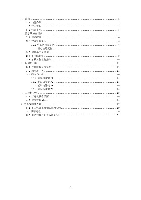
1. 前言 (2)1.1 功能介绍 (2)1.2 技术指标 (3)1.3 注意事项 (3)2. 流水线操作指南 (4)2.1 启停控制 (4)2.2 故障复位操作 (6)2.2.1单工位故障复位 (6)2.2.2 断电故障复位 (7)2.3 屏蔽单工位操作 (9)2.4 单双线控制 (9)2.5 单独工位检测操作 (10)3. 触摸屏说明 (12)3.1 控制面板按钮说明 (12)3.2 触摸屏主页 (12)3.3辅助功能键 (14)3.3.1 辅助功能键F1 (14)3.3.2 辅助功能键F2 (15)3.3.3 辅助功能键F4 (16)3.3.4 辅助功能键F6 (18)4. 工控机说明 (19)4.1 打标机操作界面 (19)4.2 监控软件wincc (19)5.常见故障及处理 (19)5.1 单工位常见机械故障及处理 (19)5.2 报警处理 (20)5.3 电感式接近开关故障处理 (21)1. 前言1.1 功能介绍如上图所示为阀门检测流水线的平面视图,标有红色开始位置为阀门的手工上件处,也是整条流水线的起点。
本瓶阀检测流水线可以实现对瓶阀的流量、低压开启气密性、高压开启气密性、高压闭合气密性、外螺纹、内螺纹通规、内螺纹止规等的精确检测,同时对检测合格的产品进行压口和打标处理,对不合格的产品根据不合格的类型进行自动分拣。
上图中,气密性检测的A线和B线是功能相同的两条线,设置A、B线主要是为了提高检测效率。
阀门检测流水线分双线、A单线、B单线三种工作模式。
默认状态为双线运行模式,即A、B线同时运行,其检测的效率为36秒/个;A单线或B单线运行模式下,检测的效率均为72秒/个。
1.2 技术指标1.主控制柜输入电源电压AC380V,最大电流20A;控制柜内部弱电电压DC24V。
2.流水线正常工作气压:0.5~0.7Mpa;高压气密性检测的高压气体压力2.5MPa,低压检测的低压气体压力0.05Mpa。
触摸屏控制器用户手册说明书
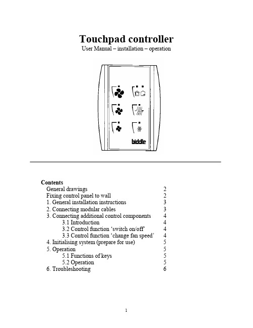
Touchpad controllerUser Manual – installation – operationContentsGeneral drawings2 Fixing control panel to wall21. General installation instructions32. Connecting modular cables33. Connecting additional control components43.1 Introduction43.2 Control function ‘switch on/off’43.3 Control function ‘change fan speed’44. Initialising system (prepare for use)55. Operation55.1 Functions of keys55.2 Operation56. Troubleshooting6Fixing control panel to wall 1234General drawings1. General installation instructions— Read this page carefully before starting the installation.— All installation work must be carried out by expert personnel.— Ensure that the appliances are disconnected from the mains before they are opened.— Avoid unnecessary contact with electronic components.Introduction:1. This manual is intended for all Biddle appliances with a built-in electronic interface.2. This manual describes the installation and use of the Biddle electronic control system.3. Several functions in this manual are only available from a certain version of a control system component. These functions are marked. Whenever you change an existing system you should compare the version number on the component with the version number in the manual.Installation details:1. Up to 10 appliances may be connected to one control panel.2. The total length of all modular cables in one system must be less than 100 metres.3. When installing the modular cable care should be taken to avoid interference with the cable by (electro)-magnetic fields as far as possible (therefore do not lay the cable close to high-voltage cables, fluorescent light starters, etc.)Components:The control system comprises the following components:1. Control panel consisting of 3, 4, 5 or 6 keys.2. Built-in interface with 3 or 6 output contacts, depending on the type of appliance.3. Modular cable including modular plugs, for connecting the control panel to one or more appliances. N.B.: B.T. type telecommunication cables are not suitable! The cable can be ordered from Biddle and is available in various lengths.Installation procedure:1. Connect modular cables + install control panel.2. Connect any customised controls, with control components with potential-free contacts.3. Provide all appliances with a power supply.4. Initialise the system.2. Connecting modular cablesA. Appliances with external connectionsType of appliance:— Modular fan coil unit (PS-B)— Air curtain (KW/MW/GW/KE/ME/GE/CAT/CAT-V)— Cassette air heater (KLV/KLV-E/KLVV)B.Appliances with internal connections Type of appliance:— Fan coil unit (B)— Extractor fan cabinetN.B.: The modular cables (X70) can be connected to both connectors (XiS)(see fold-out sheet, page 2).3. Connecting additional control componentsIf you have no control components to install, you can skip this section and go on to section 4 ‘Initialise the system’.3.1 IntroductionAs well as the basic system functions, there is also a possibility of connecting control components (e.g. room thermostat, timer BMS-controlled relay or door switch) to an appliance. Combinations of control components can also be used.N.B.: For remote switching on blocks X62/X72 volt free contacts are required. These contacts are advised to be gold plated and to have a low relay less than 20 m W to handle 1 mA at 5Vdc.Possible control functions:Control function Control range Adaptation to interface ofconnected appliance Connection points onblock X62/X72Connectionsummaryswitch on/off one appliance (local)none terminals T and G see § 3.2 switch on/off all appliances in system (general)remove jumper 6terminals T and G see § 3.2 change fan speed one appliance (local)none terminals D, P and G see § 3.3 change fan speed all appliances in system (general)remove jumper 5terminals D, P and G see § 3.3 N.B.: The function ‘switch on/off’ does not apply to the KLVV-unit. Consult the user manual of the unit when you want to connect control components to terminals T and G.3.2 Control function ‘switch on/off’1. Remove T-G bridge (X62/X72. see fold-out sheet, page 2) only from the appliance towhich the control component is to be connected.2. Connect the control component between T and G.— Contact made between T and G: Applicance stand-by.— No contact between T and G: Appliance/system off.3. General switching If the control function is to apply to the whole system, remove jumper 6(X64). This should only be done in the appliance to which the control component isconnected. Place the jumper on the reserve positions intended for it (X65), so that it can beused again later.3.3 Control function ‘change fan speed’1. Connect the control component between D and/or P and G (X62/X72, see fold-out sheet, page2). Important: do not disconnect T-G bridge.— Contact made between D and G : Appliance/system runs 1 speed higher than the controlpanel indicates (both speed and electric heating).— No contact between D and G Appliance/system working as indicated on the control panel.— Contact made between P and G Appliance/system runs at fan speed three (electric heatingstage remains unchanged, either one or two).— No contact between P and G Appliance/system working as indicated on the control panel.— Contact made between D, P and G: Appliance/system runs at fan speed three and electricheating stage two.N.B.: The functions using terminals P and G only are available from interface version V4.0Rev.06. Code IC 10 in the illustration on page 2 shows where you can find the version number.2. General switching: If the control function is to apply to the whole system, remove jumper 5(X64) as indicated in the facing illustration. This should only be applied to the appliance towhich the control component is connected. Place the jumper on the reserve positions intendedfor it (X65), so that it can be used again later.NB: General switching’ of the contact between P and G requires control pad version V2. IRev.02 or higher and interface version V4.O Rev.07 or higher. You can find the versionnumber on the printed circuit board of the control pad. In an existing system the control padcould be of a previous version. If the contact between P and G should still apply to the wholesystem, you should order a new control pad from Biddle.3. If the electric heating is not to be stepped up at the same time, remove jumper 4 (X64) asindicated in the illustration. This should be done in each appliance for which the function is required. Place the jumper on the reserve positions intended for it (X65), so that it can be used again later.14564. Initialising the system (prepare for use)When to use:1. On first installation.2. On each extension of the system.3. When checking cables.To start the procedure:1. Press keys 1, 2 and 3 simultaneously.—After 10 seconds the LEDs on keys 1 and 2 will start to flash. This flashing will continue for two minutes.— The LED on key 3 will then flash the same number of times as there are appliances in the system. The system is now ready for use.5. Operation5.1 Functions of keysLED lights when speed setting is ‘low’.LED flashes during initialisation.— Set speed to ‘low’.— Switch off appliance.— Start initialisation.LED lights when speed setting is ‘medium’LED flashes during initialisation.— Set speed to ‘medium’.— Switch off appliance.— Start initialisation.LED lights when speed setting is ‘high’.LED indicates number of appliances connected when initialisation is complete.— Set speed to ‘high’.— Switch off appliance.— Start initialisation.LED lights when electric heating is set to ‘low’.— Set electric heating to ‘low’.— Switch off electric heating.— Set electric heating to ‘low’ and speed to ‘low’.LED lights when electric heating is set to ‘high’.— Set electric heating to ‘high’.— Switch off electric heating— Set electric heating to ‘high’ and speed to ‘medium’.LED-R lights when setting is ‘Recirculate’ or standby.LED-V lights when setting is ‘Ventilate’.— Set air intake valve to ‘Ventilate’.— Set air intake valve to ‘Recirculate’.5.2 OperationA.Turn on appliance : Press key 1, 2, 3, 4 or 5.B.Turn off appliance : Press speed key (1, 2 or 3) on which the LED is illuminated. LED-R (if present) remains illuminated.Safety functions electric heating:1.The following scenarios will automatically be corrected:— Speed off, electric heating on.— Speed low, electric heating high.2. Appliance operates differently from control panel:If the appliance has just been switched off, it may start running again spontaneously.This is in order to discharge the heat stored in the heating elements.6.TroubleshootingAppliance not working:Check point Possible cause Action1no voltage on appliance check power supply to appliance2system not yet initialised start initialisation; see section 4 ‘Initialising the system’3poor contact in modular plug;check contacts (ensure plastic packaging is completely removed)4no bridge between terminals T and G fit bridge between terminals T and G on block X62/72. (see section 3‘Connecting Customised Control components’)5fuse(s) in appliance defective replace fuse (only to be done by skilled personnel)Appliance not working as expected:Check point Fault Possible cause Action/explanation1appliance (with electric heating)starts working spontaneously continued running of electricallyheated appliancesBiddle safety function; see section 5‘Operation’control components are notproperly connectedcheck system; see section 3‘Connecting Customised ControlComponents’2appliance works differently fromexpectationthe jumpers(l-3 red) on the interface are no longer in accordance with factory setting check jumper position against Specifications for factory setting jumper block X643electric heating not working appliance has overheated check maximum thermostat(see appliance manual) Factory setting jumper block X64Appliance type Jumper 1Jumper 2Jumper 3Jumper 4-6 appliance with electric heating with 2 positions present open present present CAT-air curtain open present present present KLV-E open present open present KLVV open open open presentall other appliances present present present present。
触摸屏用户手册说明书
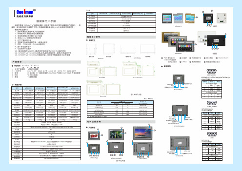
感谢您购买 COOLMAY MT 系列触摸屏。
本手册主要说明MT 系列触摸屏的产品特性、一般规格、硬件接口和软件设置方法等。
详细编程请参见《COOLMAY 触摸屏使用手册》。
触摸屏的主要特点:1、提供大量的矢量图库及支持自建图库2、高精度/高可靠性的电阻式触摸面板3、支持各种格式静态图片及GIF 动画4、支持windows 所提供的所有字体5、6万TFT 真彩显示器6、支持配方功能和数据存储、U 盘导出数据7、自带一个RS232和一个RS485通讯口8、基本版可竖屏显示9、可选装网口或音频10、基本版(基于WINCE 5.0系统)和升级版(基于WINCE 7.0系统)可选11、MT6037H /MT6050H (A )灰色/金色/银色面板可选,黑色/白色底壳可选 12、MT6037H /MT6050H (A )可墙体安装,可应用于智能家居/工业等领域产品信息1、 公司产品系列 MT 系列触摸屏2、 HMI 尺寸 6037:3.5寸 6043: 4.3寸 6050: 5寸 6070: 7寸 6100: 10寸3、 版本 H : 基本版 HV : 基本版竖屏;HA /HAS : 升级版 HAV /HAVS : 升级版竖屏4、 网口 W : 网口(选装)5、 音频 Y : 音频(选装)命名规则MT 123456070图1 安装尺寸图MT6100HAMT6043HMT6070H(A/AS)电气设计参考产品构造COM :PLC 与触摸屏 通讯上时快闪安装尺寸机械设计参考规格参数触摸屏用户手册表三:安装尺寸型 号安装尺寸外形尺寸W*H*D(mm)A(mm)B(mm)MT6050H(A)MT6070H(A/AS)MT6100HA13719426172138180146*88*25212*148*40275*194*36电源用端子台 USB 口PWR :通电指示灯触摸屏编程口液晶屏RS232/RS485网口(选装) ◆◆◆◆YW H--6143257图2 产品构造※ 更多规格批量客户可定制MT6043H(A)MT6070H(A/AS)MT6100HAMT6037H背面图MT6050H背面图型号MT6037H 3.5"TFT 液晶屏 4.3"TFT 液晶屏7.0"TFT 液晶屏10.2"TFT 液晶屏MT6043H(A)MT6070H(A/AS)MT6100HA 320*240480*272800*480/1024*6001024*60088*88*25mm 134*102*30mm 212*148*40mm 275*194*36mm 72*72mm 119*93mm 194*138mm 261*180mm 73*56mm 97*56mm 154*87mm 222*133mm 300cd/m²300cd/m²300cd/m²300cd/m²LED LED LED LED 128MB Flash ROM 65536真彩4线电阻屏100mA/24V150mA/24V200mA/24V280mA/24VCOM1: RS232 COM2: RS485400:1H 系列: ARM9内核 640MHz HA(S)系列: Cortex A8 720MHz-1GHz20ms 以内有电源失效检测12-24VDC ±10%<150mA @24VDC 符合EN50081-2和EN50082-2标准符合FCC Class A电压1500Vp -p ,脉冲周期1μs ,持续1s 10-25Hz (X 、Y 、Z 方向2G 30分钟)超过10M Ω@500VDC工程塑料ABS +PC 500VAC 1分钟IP65(前面板)0~50℃20~90%RH -20~70℃显示屏分辨率外形尺寸安装开孔尺寸显示尺寸亮度背光类型存储器颜色触摸面板功耗通讯端口对比度CPU 容许掉电USB??系统诊断供电电源认证FCC 兼容性抗干扰测试防震测试绝缘电阻外壳材料耐压测试防护等级工作环境温度工作环境湿度存储温度65536真彩4线电阻屏65536真彩4线电阻屏65536真彩4线电阻屏0.3kg0.33kg0.54kg0.7kg重量MT6050H(A)5.0"TFT 液晶屏800*480146*88*25mm 137*72mm 108*65mm 300cd/m²LED 150mA/24V65536真彩4线电阻屏0.33kg128MB Flash ROM 128MB Flash ROM 128MB Flash ROM 128MB Flash ROMH 系列: 64MB HA(S)系列: 128M运行内存121264357643572264357673541234657侧面四个安装扣位孔888888MT6037H 727288*88*25MT6043H(A)11993134*102*30MT6037H硬件接口◆FG 0V 24V触摸屏232/485口触摸屏下载口USB口网口COM1/COM2MT6043H(A)/MT6043KH(A)/MT6050KH(A) COM口引脚定义管脚号信号描述23TXDRXD 发送接收5地线GNDRS232通讯口定义RS485通讯口定义16BA485-485+MT6043H(A)背光寿命60000小时60000小时60000小时60000小时60000小时以太网口可选装万年历输入电压有常规为DC24±10%VDC ,也可以特别做成DC12V /DC5V 电源输入墙体安装镶嵌安装墙体安装镶嵌安装MT6050H(A)型号MT6037H MT6043H(A)MT6070H(A/AS)MT6100HAMT6050H(A)自然风冷冷却方式接上表FG 0V 24V 触摸屏485口USB口触摸屏下载口触摸屏232/485口网口(选装)(同COM1中的485口)COM1/COM2MT6070H(A/AS ) COM口引脚定义管脚号信号描述23TXDRXD 发送接收5地线GNDCOM1 RS232通讯口定义COM1/COM2 RS485通讯口定义16BA 485-485+MT6070H(A/AS)FG 0V 24V USB口触摸屏下载口网口(选装)触摸屏232/485口COM1MT6100HACOM口引脚定义管脚号信号描述23TXDRXD 发送接收5地线GNDRS232通讯口定义RS485通讯口定义16BA 485-485+MT6100HA* 编程软件触摸屏:CoolMayHMI 触摸屏编程软件* 详细资料参考《CoolMayHMI 触摸屏使用手册》温馨提示.......................................................01产品特点.......................................................02产品信息.......................................................03 电气参数......................................................04 机械设计参考................................................05 产品构造.......................................................06 硬件接口.......................................................07软件参数设置................................................08 与个厂牌联机说明.........................................09 抗干扰处理...........................................10 编程参考.......................................................11资料参考. (12)深圳市顾美科技有限公司 86960332 26051858 26400661营销QQ:800053919邮箱:**************.com 网址:2018/02 版目 录1、请在确认了本产品的电源电压范围(常规产品电源仅限24V?DC!建议电源的 输出功率为18W及以上)和正确接线之后再通电,以避免损坏。
Elo 互动式数字标牌触摸显示器用户手册说明书
用户手册Elo Touch SolutionsET3201L 32 英寸互动式数字标牌触摸显示器 ET4201L 42 英寸互动式数字标牌触摸显示器 ET5501L 55 英寸互动式数字标牌触摸显示器 ET7001L 70 英寸互动式数字标牌触摸显示器SW601995修订版H版权所有© 2014 Elo Touch Solutions, Inc. 保留所有权利。
未经Elo Touch Solutions, Inc. 的书面许可,不得以任何形式或方法(包括但不限于电子、磁性、光学、化学方法或手册等)复制、传输或改编本出版物的任何部分,不得将其存储到检索系统,不得将其翻译成任何语言或计算机语言。
免责声明本文档中的信息有可能在未通知的情况下进行更改。
Elo Touch Solutions, Inc. 及其附属公司(共同称为“Elo”)对本出版物的内容不提供任何形式的陈述或担保,并且特别声明拒绝对有特定目的适销性或适用性提供任何默示担保。
Elo 保留对本出版物进行修订并对其内容不断进行变更,而不将这样的修订和变更通知任何人的权利。
商标声明AccuTouch、CarrollTouch、Elo、Elo(徽标)、Elo Touch、Elo Touch Solutions、Elo TouchSystems、IntelliTouch、iTouch、SecureTouch、TouchTools和VuPoint为 Elo 及其附属公司的商标。
Windows 为 Microsoft Corporation 的商标。
目录第 1 章 – 简介4第 2 章 – 打开包装5第 3 章 – 触摸显示器的安装7第 4 章 – 安装 9 第 5 章 – 操作 13 第 6 章 – 技术支持 30第 7 章 – 安全与维护 31第 8 章 – 法规信息 31第 9 章 – 担保信息 37第 1 章:简介产品说明新的互动式数字标牌 (IDS) 触摸显示器集Elo Touch Solutions 的可靠性能和触摸屏技术与显示屏设计领域的最新进展于一身。
交互式触摸式电子白板软件使用手册.

交互式触摸式电子白板软件使用手册登陆界面:用户可以用公共用户的方式来登陆,即直接点击登陆按键。
主控制工具栏控制模式:1.通过与电脑、投影机组成交互式演示系统,无需专用笔,使用任何不透明物体,包括手指、网球等均可完全操作、控制计算机。
电脑的一切操作均可在电子白板上实现并同步显示,在电子白板上的操作也均可在电脑上同步显示,并可存储。
注解模式:在电子白板上进行书写、标注、任意擦除,更有普通笔、毛笔、荧光笔、排笔四种书写、标注的笔形选择,可随意调整笔的粗细和颜色,而且荧光笔还可以设置颜色的透明度。
配套功能强大的教学辅助工具,更好的实现教师和同学的互动。
一.普通基本功能普通笔:具有书写整齐平滑特点,更加适合字母、数字书写。
◆毛笔:根据中国书法特点开发的毛笔书写效果,精彩展现中国毛笔书法艺术。
◆荧光笔:真正意义上的荧光笔功能,可自由更改其透明度,适用于标注、突出重点◆排笔:适用于书写新疆文字、阿拉伯文字。
有美术字体的效果。
◆以上四种笔都可调节笔的粗细、颜色,书写不同大小的文字和不同粗细的线条。
◆电子板擦:可以擦除我们书写的内容,电子板擦有“小板擦”、“中板擦”、“大板擦”和“区域擦除”四种.◆画直线和几何图形:可直接在白板上画出直线和各种规范的圆、直线、三角形、矩形等,有效提高了画图的速度及效果智能画笔:可以将我们手绘的几何图形转化为标准的几何图形。
画直线、几何图形在加上智能画笔,体现出了IPBoard 软件强大的绘图功能,可以快速的画出常用的几何图形,以及比较复杂的组合图形。
◆超强的对象编辑功能:可以对每一个对象进行后编辑,包括复制、粘贴、删除、组合、锁定、图层调整、平移、缩放、旋转等。
二、教学辅助工具◆放大镜功能:可以随意将选定区域进行放大或缩小,对重点看的更清楚,有助于改善相互交流的效果。
◆屏幕幕布:实现上下、左右拉幕,对屏幕上的内容进行遮蔽,留出有针对性的信息供演示,方便教学课件的演示。
◆页面移动:能够移动页面把页面移动到合适书写的位置,增强了教学的灵活性,页面可以上下移动◆探照灯:对需要突出的内容做重点显示,同时屏蔽其他内容,光斑形状和背景透明度都可以进行调节。
触摸互动手册
1.触摸互动伴随着传统信息发布系统的在各个行业的日渐普及,人们已经不再只满足于只能被动的接受各种媒体信息,他们更加渴望能够人机互动,对一体机(广告机)上正在播放的内容,很想上去摸一下,这是人的天性,有一种探险和猎奇的心理。
如果他们触摸之后,没有任何反应,他们可能会很失望的离开。
多媒体互动软件能够很好的升用户体验,他将传统的信息发布和体验极好的触摸互动完美结合,编辑简单,互动功能丰富。
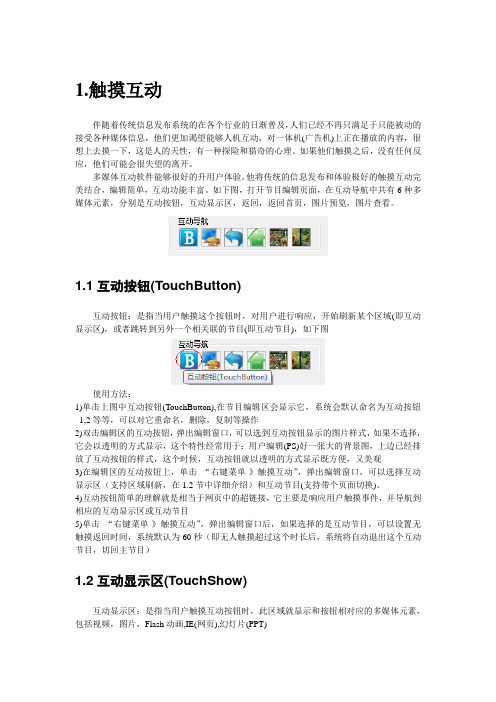
如下图,打开节目编辑页面,在互动导航中共有6种多媒体元素,分别是互动按钮,互动显示区,返回,返回首页,图片预览,图片查看。
1.1互动按钮(TouchButton)互动按钮:是指当用户触摸这个按钮时,对用户进行响应,开始刷新某个区域(即互动显示区),或者跳转到另外一个相关联的节目(即互动节目),如下图使用方法:1)单击上图中互动按钮(TouchButton),在节目编辑区会显示它,系统会默认命名为互动按钮_1,2等等,可以对它重命名,删除,复制等操作2)双击编辑区的互动按钮,弹出编辑窗口,可以选到互动按钮显示的图片样式,如果不选择,它会以透明的方式显示,这个特性经常用于:用户编辑(PS)好一张大的背景图,上边已经排放了互动按钮的样式,这个时候,互动按钮就以透明的方式显示既方便,又美观3)在编辑区的互动按钮上,单击“右键菜单-》触摸互动”,弹出编辑窗口,可以选择互动显示区(支持区域刷新,在1.2节中详细介绍)和互动节目(支持带个页面切换)。
4)互动按钮简单的理解就是相当于网页中的超链接,它主要是响应用户触摸事件,并导航到相应的互动显示区或互动节目5)单击“右键菜单-》触摸互动”,弹出编辑窗口后,如果选择的是互动节目,可以设置无触摸返回时间,系统默认为60秒(即无人触摸超过这个时长后,系统将自动退出这个互动节目,切回主节目)1.2互动显示区(TouchShow)互动显示区:是指当用户触摸互动按钮时,此区域就显示和按钮相对应的多媒体元素,包括视频,图片,Flash动画,IE(网页),幻灯片(PPT)使用方法:1)单击上图中互动显示区(TouchShow),在节目编辑区会显示它,系统会默认命名为互动显示区_1,2等等,可以对它重命名,删除,复制等操作2)双击编辑区的互动显示区,弹出编辑窗口,可以选择视频,图片,幻灯片等,并为其指定对应的互动按钮,如果不选择,默认为无,即当用户不单击和显示区相关联的按钮时,互动显示区默认播放显示这些标识为无的多媒体元素,如果选择了互动按钮,则用户触摸单击这个互动按钮时就播放显示刚才已经选择的多媒体元素。
hitech 触摸屏使用手册
Hitech 触摸屏使用手册一、概述1.1 感谢您购物Hitech触摸屏产品。
本使用手册旨在向您介绍如何正确使用Hitech触摸屏,并为您提供使用过程中可能遇到的问题的解决方案。
1.2 在使用本产品前,请务必仔细阅读本手册并按照指示进行操作,以确保您能充分利用Hitech触摸屏的功能。
二、产品概述2.1 Hitech触摸屏是一种先进的人机交互设备,能够通过触摸操作实现对设备的控制和指令输入。
2.2 产品特点:灵敏的触摸响应、高清的显示效果、多点触摸支持、耐用的屏幕材料、易于安装和维护。
2.3 适用范围:工业自动化控制、商业展示展览、交互式广告媒体、智能家居控制等领域。
2.4 注意事项:请避免在触摸屏表面使用尖锐物体或过度施加压力,以免损坏屏幕。
三、使用指南3.1 开机和关机a) 开机:按下电源按钮并保持数秒,待屏幕亮起即表示开机成功。
b) 关机:进入系统设置界面,选择“关机”选项完成关机操作。
3.2 触摸操作a) 单点触摸:轻触屏幕即可完成单点触摸操作,适用于简单的选择、拖动等操作。
b) 多点触摸:使用两个以上手指在屏幕上进行操作,可以实现缩放、旋转等操作。
3.3 菜单操作a) 主菜单:轻触屏幕任意位置,弹出主菜单选项,可根据需求选择不同功能。
b) 设置菜单:进入系统设置菜单,可进行屏幕亮度调节、音量调节、语言选择等操作。
3.4 输入操作a) 虚拟键盘:在需要输入文字或数字时,触摸屏会自动弹出虚拟键盘,用户可通过触摸屏进行输入操作。
b) 手写输入:部分Hitech触摸屏产品支持手写输入功能,用户可直接用手指或专用笔进行书写,进行更自然的输入操作。
3.5 网络连接a) 有线连接:通过网线连接,可直接接入局域网或互联网,实现数据传输和上线操作。
b) 无线连接:部分Hitech触摸屏产品支持Wi-Fi连接功能,用户可通过无线网络进行数据传输和上线操作。
3.6 外接设备a) USB接口:部分Hitech触摸屏产品支持USB接口,用户可连接U 盘、键盘、鼠标等外部设备进行数据传输和操作。
BenQ RM7501K RM8601K 交互式平板 用户手册说明书

RM7501K/RM8601K 交互式平板用户手册免责声明BenQ Corporation 对于本文档的内容不做任何明示或隐含的陈述或担保。
BenQCorporation 保留修订本出版物和随时修改本文档内容而不需通知任何人的权利。
版权版权所有 2018 BenQ Corporation。
保留所有权利。
未经 BenQ Corporation 事先书面许可,不得以任何形式和电子、机械、磁性、光学、化学、手工以及其它任何方式复制、传播和转录本出版物的任何部分,也不得将任何部分存储到检索系统中或翻译成任何语言或电脑语言。
目录i目录安全警告和预防措施 (1)重要安全注意事项 (2)显示器液晶面板注意事项 (2)遥控器安全注意事项 (3)电池安全指示 (3)BenQ ecoFACTS (4)包装内容 (5)设置显示器 (6)固定显示器 (6)显示器各部位及其功能 (8)前/后面板 (8)输入/输出端子 (9)遥控器 (10)使用遥控器 (12)连接 (13)连接音频 / 视频信号 (13)连接多媒体输入 (16)连接触摸模块 (17)连接电源 (18)安装和删除 OPS 模块 (19)使用触摸屏 (20)使用触摸屏的重要说明 (24)基本操作 (25)打开或关闭显示器 (25)初始化设置 (25)边栏菜单 (26)切换输入信号 (27)护眼解决方案 (28)下载软件 (28)设置 Internet 连接 (28)更新软件 (29)ii目录恢复到默认设置 (30)调整音频音量 (30)OSD(屏幕显示)菜单 (31)OSD 菜单概述 (31)OSD 菜单操作 (32)图像菜单 (33)声音菜单 (34)菜单设置菜单 (35)使用 Android 操作系统 (37)设置 (38)本地应用 (39)BenQ Suggest (40)Browser (41)ES File Explorer (42)InstaQPrint (43)InstaShare (44)Multimedia (46)WPS Office (47)产品信息 (49)规格 (49)尺寸 (52)支持的输入 (54)故障排除 (55)8/10/20安全警告和预防措施1安全警告和预防措施• 电源线的电源插头应该保持随时可使用。
触摸屏使用说明书
2
触摸屏使用说明书
容易碎,除需要检查外尽量不要碰它们。如果在装配安装过程中换能器意外破碎或电缆布线 被拉松的话,触摸屏将无法工作。切勿重拉重压触摸屏电缆。
安装需要的用品和工具
用品 防护衣、眼镜、手套、橡皮围裙 刀 干净的防静电板 装拆下部件的小容器 泡沫塑料块 防尘条(安装表面声波触摸屏用) 记号笔 软布和酒精(或玻璃清洁剂) 快速粘接剂 电缆扎带 尼龙隔离物和垫圈 为重新安装显像管前罩或底板替换的螺丝 双面泡沫胶带 绝缘胶带
拆除固定在前罩上的显像管
如果显像管固定在前罩上,按下列过程拆卸显示器。如果显像管固定在底座上,跳过这 一节。
如果显像管固定在前罩上,必须拆卸显示器,让显像管完全露出。拆卸过程、电线的位 置和连接电缆的类型因显示器不同而不同。
在把显像管从前罩分离开前,一定要断开所有的电缆。你也必须拆掉视频板,视频板连 接着显像管管颈和主板。
4.显像管向上放,用一个泡沫塑料块支撑管颈。这样可以降低过多的压力、避免划 伤、防止损坏。
9
触摸屏使用说明书
拆卸固定在底座上的显像管
如果显像管固定在底座上,你只需要移走前罩,露出显像管的面。显像管仍固定在底座 上。
1.拧下固定前罩到底座上的螺钉。也可能有一个或几个释放夹固定前罩。 2.断开在前罩和底座间的开关或电线。为以后正确的装配,给电线或开关作标记。常 见的连接电缆包括:
触摸屏使用说明书 User’s Manual
0
目录
触摸屏使用说明书
◆
触摸屏硬件安装 …………………………………………... 1
安装准备
…………………………………………...1
触摸屏安装步骤过程 ……………………………………... 4
安装注意事项 …………………………………………...17
Philips LCD Touch监display说明书

PhilipsLCD Touch monitormultimediaFull HDBDT6551VMMore audience interactionwith the multi user touch screen LCD DisplayDeliver vital information or marketing messages to your audience in startling clarity. Andthanks to the interactive touchscreen, you can also engage your customer much closerthan ever before.Operational flexibility•True multi touch with 6 simultaneous touch points•Infrared Touch•Software Independent•Designed for 24/7 operation•Smart insert in the backcover to place a small pcOptimized for public viewing•High brightness for clearer images•HDMI inputLower total cost of ownership•SmartPower for energy savingIssue date 2022-07-14Version: 1.0.112 NC: 8670 000 86541EAN: 87 12581 63237 3© 2022 Koninklijke Philips N.V.All Rights reserved.Specifications are subject to change without notice. Trademarks are the property of Koninklijke Philips N.V. or their respective SpecificationsLCD Touch monitor165 cm (65") multimedia, Full HDHighlights6 simultaneous touch pointsEnjoy a more interactive experience with up to 6 touch points at the same time. Ideal for when you have more than one user to interact with your application simultaneously, the 6 touch points offer an extremely cost-effective solution.Designed for 24/7 operationDesigned for 24/7 operationHDMI inputHDMI makes an uncompressed digital RGB connection from the source to the screen. Byeliminating conversion to an analog signal, it delivers an unblemished image. The nondegraded signal reduces flicker and leads to a clearer picture. HDMI intelligently communicates the highest outputresolution with the source device. The HDMI input is fully backward compatible with DVI sources but includes digital audio. HDMI uses HDCP copy protection.High brightnessEnjoy a clearer image in areas with greater ambient brightness thanks to the 700 nit panel. Your audience can enjoy better image quality in locations that are away from direct sunlight yet still brighter than average, optimizing the viewing experience.Infrared TouchWith an invisible infrared grid on the top of the screen, you can enjoy amazing accuracy and fast response times, even when touched by a finger, glove or stylus. And no “ghost points”.Smart insertProfessional PC’s are part of most multi-user Touch Screen installations. Quite often they add additional depth to the public display and a lot of cable clutter. This Multi-user Touch Screen contains a Smart insert in the backcover that will fit many professional compact PC’s. In addition it offers provisions for efficient cable management.SmartPowerThe backlight intensity can be controlled and pre-set by the system to reduce the power consumption by up to 50%, which saves substantially on energy costs.Software IndependentOur touch screens are software independent and work with most touch screen software commercially available, including Windows XP/7 and Mac OS, Omnitapps – BMT1909/00. Connect via USB to a PCor laptop.Picture/Display•Diagonal screen size: 65 inch / 165 cm •Panel resolution: 1920x1080p•Optimum resolution: 1920 x 1080 @ 60Hz •Brightness: 700 cd/m²•Contrast ratio (typical): 2500:1•Response time (typical): 8 ms •Aspect ratio: 16:9•Viewing angle: 178º (H) / 178º (V)•Pixel pitch: 0.744 x 0.744 mm •Display colors: 1.06 Billion colorsSupported Display Resolution•Computer formats Resolution Refresh rate 640 x 480 60, 67, 72, 75Hz 800 x 600 56, 60, 72, 75Hz 1024 x 768 60Hz 1280 x 800 60Hz 1280 x 1024 60Hz 1360 x 768 60Hz 1366 x 768 60Hz 1440 x 900 60 Hz 1600 x 1200 60Hz 1920 x 1080 60Hz 1920 x 1200 60Hz •Video formats Resolution Refresh rate 480i 60Hz 480p 60Hz 576i 50Hz 576p 50Hz 720p 50, 60Hz 1080i 50, 60Hz 1080p 50, 60HzConnectivity•PC: VGA-in D-Sub 15HD, VGA-out D-Sub 15HD, DVI-D x1, RS232 D-Sub9, RS232 D-sub9 output, 3.5 mm PC audio input x1•AV input: HDMI x1, Component RCA, Composite (RCA) x1, S-video x1, Audio (L/R) x1•AV output: Audio (L/R) x2•Other connections: AC-out, External loudspeaker connectorConvenience•Placement: Portrait•Picture in picture: PBP, PIP, POP•Screen saving functions: Pixel shift, Low brightness •Keyboard control: Hidden, Lockable •Remote control signal: Lockable•Ease of installation: AC Out, Carrying Handles, Smart Insert•Energy saving functions: Ambient light sensor,Smart Power•Safety control functions: Heat Control, Temperature Sensor•Picture performance: Advanced color control •Network controllable: RS232Dimensions•Set dimensions (W x H x D): 1499 x 875 x 140.70mm•Bezel thickness: 32.5 mm horizontal, 28.5 mm vertical•Product weight: 85 kg•Smart Insert mount: 300 x 320 x 64 mm•Wall Mount: 400 x 400 mm (Set), 100 x 100 mm (Smart insert)Operating conditions•Temperature range (operation): 0 - 40 °C •Relative humidity: 10 - 90 %•MTBF: 50.000 hour(s)Power•Mains power: 90-264 VAC, 50/60Hz •Consumption (On mode): Typical 324W •Standby power consumption: < 1WSound•Built-in speakers: 2 x 12W (8 Ohm)Accessories•Included accessories: Remote Control, Batteries for remote control, AC Power Cord, VGA cable, User manual on CD-ROM, Owner's Manual, Touch Screen Driver, Smart insertMiscellaneous•Bezel: black, RAL 9005F13•Warranty: Europe 3 years•On-Screen Display Languages: English, French, German, Italian, Polish, Turkish, Russian, Simplified Chinese•Regulatory approvals: CCC, CE, FCC, Class B, RoHS, UL/cULPackaging Data•Packaging dimensions (WxHxD):: 1571 x 1089 x 324 mm•Tare weight: 8.5 kg•Number of products included: 1Interactivity•Multi-touch technology: 6 Touch pointssimultaneously, Infrared touch, USB connection, 6 mm safety glass。
- 1、下载文档前请自行甄别文档内容的完整性,平台不提供额外的编辑、内容补充、找答案等附加服务。
- 2、"仅部分预览"的文档,不可在线预览部分如存在完整性等问题,可反馈申请退款(可完整预览的文档不适用该条件!)。
- 3、如文档侵犯您的权益,请联系客服反馈,我们会尽快为您处理(人工客服工作时间:9:00-18:30)。
交互式触摸显示器用户使用手册使用手册交互式触摸显示器使用手册敬告用户敬爱的用户:感谢您购买我公司新一代交互式触摸显示器产品,衷心希望本产品能为您带来全新的视听享受。
在使用本产品前,请您仔细阅读本说明书中所有的安全操作的说明。
它会让您享受到本机的各种功能,为你的使用提供方便。
为了方便您快速掌握产品的基本操作,我们编撰了本使用说明书。
说明书的内容在编撰过程中我们尽力避免错误,确保说明书的信息准确,可靠,然而篇幅所限,说明书的内容不可能涵盖用户使用过程中可能碰到的所有问题,有些内容虽然能够涵盖,但是可能没有提供非常详尽的说明。
由此产生的不便,敬请谅解。
本公司一直致力于不断改善其产品的性能和可靠性。
因此,本使用说明书的硬件等配置可能与您实际购买的产品略有不同,但是此差异不会实质性地影响您使用此产品。
谢谢你的合作!重要安全事项在使用本产品无比阅读1.预读这些注意事项。
2.妥善保管这些注意事项。
3.遵循所有警告。
4.遵循所有知道说明。
5.不要在靠近水的地方使用本产品。
6.仅使用干布进行清洁。
7.不要挡住任何通风口。
按照制造商知道说明进行安装。
8.不要将本产品安装在热源旁边,如散热器、调温器、火炉或其它产生热量的设备。
9.不要損坏极性或接地型插头的安全设计。
极性插头有一宽一窄两个插片。
接地型插头有两个插片和一个接地插片。
宽插片或接地插片用于安全目的。
当提供的插头无法插入插座时,请与电工联系,以换成合适的插座。
10.不要踩踏电源线,不要在插头、便利插座、与本產品连接的部位等处卡主电源线。
11.仅使用制造商指定的连接件/附件。
仅使用制造商指定的或隨本产品一起销售的推车、平台、三腳架、支架或桌子等。
使用推车移动本产品实,应小心谨慎一避免因翻倒而受伤。
12.在雷電天气条件下或者长时间不使用时,请拔掉本产品的电源线。
13.委托专业维修人员进行维修。
当本产品由于任何原因而损坏时,如电源线或插头损坏、液体溅入或物品掉入本产品内部、遭受雨淋或受潮、工作不正常、或掉落等,应维修本产品。
14.损坏时进行维修,在下列情况下,应由专业维修人员维修本产品:A. 电源线或插头损坏B. 物品掉入或液体溅入产品內部C. 本产品遭受雨淋D. 本产品工作不正常或者性能发生明显变化E. 本产品掉落,或者机壳损坏15.倾斜╱稳定性–所有电视的机壳设计的倾斜和稳定性属性均必须符合建议的相关国际标准。
•不要在机壳前部或顶部施加过多的拉力而破坏这些设计标准,否则最终可能会导致本产品翻倒。
•此外,不要在机壳顶部放置电子设备╱玩具等,以避免对您或幼儿带来危害。
这些物品一旦从顶部意外掉落,可能导致本产品损坏/或人员伤害。
16.壁挂或吊顶安裝–以壁挂或吊顶方式安装本产品时,必须遵循制造商的建议。
17.电源线–室外天线应远离电源线。
18.室外天线接地–接收器连接外部天线时,务必将天线系统接地,以便对电压突变和静电积聚提供一定程序的防护。
19.物品和液体进入–應避免物品或液体通过机壳上的开口掉入或溅入本产品内部。
20.电池使用注意事项–为防止因电池泄漏而导致人身伤害、财产损失、或本产品损坏:•正确安装电池,按照本产品上的标记放置 + 和–极。
•不要混合使用电池(新旧电池或者碳性和碱性电池等)。
•长时间不使用本产品时,应取出电池。
21.为保持良好通风,应在本产品四周留出至少10.16 至15.24厘米的空间。
不要将本产品放置在地毯上。
22.不要让液体滴落或溅落到设备上。
23.不要让设备遭受雨淋或受潮,也不要将盛有液体的物品(如花瓶)放在设备上。
24.设备必须连接到接地保护的电源插座。
25.设备的连接开关用作吃设备的断开装置,断开装置应始终处于可操作状态。
目录用户警告 (2)重要安全事项 (3)目录 (5)产品介绍 (6)技术规格 (7)交互式触摸显示器正面 (8)交互式触摸显示器后视图 (9)交互式触摸显示器侧/后置端口说明 (10)包装清单 (11)遥控器说明 (12)菜单操作指引 (14)附件 (23)电脑系统(选配) (24)使用指引 (25)常见故障排除 (27)中国RoHS法规标示要 (30)交互式触摸显示器用户使用手册产品简介注:交互式触摸显示器外观以实物为准(拍本公司实物)交互式触摸显示器是人性化科技的完美应用,它结合了先进的红外触摸技术和大尺寸数字全高清显像技术(集电视、电脑、触摸于一体)。
可用手指或书写笔直接在屏幕上触摸、书写、画图、标注及控制与其相连接的计算机。
本公司为用户提供“人机交互”尖端人性化科技的完美体验。
主要功能精确触摸:交互式触摸显示器同时也是一台高精度的触摸显示屏,可以直接用手指、笔或其他物体方便地进行点击、拖拽等动作,取代鼠标轻松完成各项操作。
人机交互:交互式触摸显示器是计算机的显示设备。
通过与计算机相连,用户可用书写笔或手指直接在显示屏幕上进行书写、绘图等。
全高清显示:互式触摸显示器同时具备高分辨率电脑显示屏、高清电视、视频监控器等功能。
内置电脑(选配):式触摸显示器可根据客户需要加装不同配置电脑,集电脑、电视、触摸功能为一体的电脑电视触摸一体机,交互式触摸显示器内置电脑采用模块化设计,可独立拆卸,方便维护。
交互式触摸显示器正面A-遥控接收及按键指示灯 B-开关机键C-信号源选择键 D-菜单键E-音量增大/音量减小 F-节目增、减/菜单项目选择键G-按键功能设置键(增加中文版本,增加SET键)(图中删除脚架)注:面板以实物为准提示:快捷功能按键提供了便捷的常用功能操作/设置。
您也可以根据需要,使用遥控器来设置/操作交互式触摸显示器菜单。
交互式触摸显示器后视图注:后面插口以实物为准(和结构确定端口方式,脚架删除)电脑后写选配1.电源输入 7.分量输入 Pr/Pb/Y2.耳机输出 8. USB 13. USB 2 9.HDMI 14. AV2输入(视频/左右音频)10.HDMI 25.天线(RF输入) 11.VGA/音频输入6. S-VIDEO 12.AV1输入(视频/左右音频)交互式触摸显示器侧/后置端口说明支架均不需要侧面注:后板面口以实物为准注:因电脑配置不同请以具体实物为准视频输入:将电脑VGA接口连接到交互式触摸显示器VGA输入接口,信号源选择电脑:或是电脑HDMI接口连接到交互式触摸显示器HDMI接口中的一组,信号源选择与您接入相对应的HDMI接口(电脑含有HDMI接口)。
音频输入:视频输入为VGA输入时,电脑音频输出接口连接到交互式触摸显示器的音频输入接口,HDMI输入时可免除该条连线。
触控输入:电脑USB接口连接到一体机的触摸屏USB接口。
不带PC的交互式触摸显示器包装清单:带PC得交互式触摸显示器包装清单:交互式触摸显示器用户使用手册遥控器说明交互式触摸显示器用户使用手册遥控器说明-输入源选择,如下图所示:2、菜单操作用户可以通过遥控器或者按键实现功能操作,主菜单控制按键: “Menu”, ▲,▼,◄,►,“OK” , “Exit” ;按“Menu”键进入主菜单,也可以返回上一级菜单,有五个主菜单:频道,图像,声音,时间,设定。
• 按◄/► 选择菜单。
• 按▲/▼ 选择菜单里项目。
• 按“OK”键进入。
• 按“Exit”键退出。
3、各菜单功能 3.1、频道按“MENU ”键进入频道菜单,如下:菜单操作指引交互式触摸显示器用户使用手册(1)、自动搜台: ATV 自动搜台,操作如下:将光标移至“自动搜台”处,再按“OK”键,开始自动搜台。
搜台过程中,如果用户想退出,则按“MENU”或”EXIT”,再进行选择按“◄”退出,按“►”继续搜台,如下图所示。
(2). ATV 手动搜台,操作如下:a. 将光标移至“手动搜台”处,按“OK ”键进入手动搜台菜单,按“▲/▼”移动光标到“存储到1”,按 “◄/►”可选择1-100,移动光标到“伴音制式DK ”,选择电视图像及伴音制式,如下图所示。
b. 按 “▲/▼”选择“搜索”,如果用户想停止搜台,按“MENU”,“EXIT”退出。
(3). 频道编辑:a. 按“Menu”或“◄/►”选到频道菜单(图5) , 按“▲/▼”将光标移到“频道编辑”项。
b. 按 “OK”确认选择(如下图所示), 按“Menu”退出。
3.2、图像(1). 按“◄/►”键在主菜单选择图像。
(2). 按“▲/▼”键选择你想要调节的选项,按“◄/►”键调节选项值。
(3). 设定完成后,按“MENU”键返回上一层菜单,按“EXIT”键可退出菜单。
a. 图像模式: 按“◄/►”键选择你想要的图像模式(标准,柔和,用户,动态);(在用户状态下,可以调节对比度,背光,彩色,清晰度)b. 色温: 按“◄/►”键调整图像色温(标准,冷色,暖色,用户);(在用户状态下,可以调节红绿蓝)c. 屏显模式: 按“▲/▼”选择显示比例;(自动,4:3,16:9)d. 降噪: 按“▲/▼”键调整降噪幅度(关,低,中,高);e. 屏幕: 按“▲/▼”选择(仅为VGA 输入)。
3.3 、声音按“Menu” 键打开菜单;(1). 按“◄/►”键在主菜单选择声音;(2). 按“▲/▼”键选择你想要调节的选项,按“◄/►”键调节选项值;(3). 设定完成后,按“Menu” 键返回上一层菜单,按“EXIT”键可退出菜单。
菜单操作指引a. 声音模式: 按“◄/►”键选择你想要的声音模式(标准,音乐,用户,运动,电影);(在用户状态下,可以调节高低音)b. 平衡: 按“◄/►”键调整左右声音均衡;c. 自动音量: 按“◄/►”键选择自动音量的开关模式;d. 同轴模式: 按“◄/►”键进入同轴模式选择(PCM,自动)。
3.4 、时间按“Menu”键打来主菜单;(1). 按“◄/►”键在主菜单选择时间;(2). 按“▲/▼”键选择你想要调节的选项,按“◄/►”键调节选项值;(3). 设定完成后,按“Menu” 键返回上一层菜单,按”EXIT”键可退出菜单。
a. 时钟:在时钟菜单下, 按 “▲/▼”移动光标到“时钟”项,按 “OK” 键进入设置时钟菜单(如下图所示)b.关机时间:在时钟菜单下, 按 ▼/▲移动光标到“关机”项,按“OK” 键进入设置关机时间菜单(下图所示)。
c. 开机时间:在时钟菜单下, 按▼/▲移动光标到“开机”项,按“OK”键进入设置开机时间菜单(如下图所示)。
d. 睡眠时间:选择(关,10 分,20 分,30 分,60 分,90 分,120 分,240 分)。
e. 自动休眠:按“OK”选择开与关。
3.5、 设定按 “Menu”键打来主菜单;(1). 按“◄/►”键在主菜单选择设定;(2). 按“▼/▲”键选择你想要调节的选项,按 “◄/►”键调节选项值;(3). 设定完成后,按“Menu” 键返回上一层菜单,按“EXIT”键可退出菜单。
