霍尼伟尔气体侦测器中文说明书
BW Technologies by Honeywell 的气体检测仪说明书

Certificate of Compliance Certificate:1730355 Master Contract: 157918 Project:70024685 Date Issued: April 05, 2015Issued to: BW Technologies by Honeywell2840 2nd Ave SECalgary, Alberta T2A 7X9CANADAAttention: Stephen Uliasz The products listed below are eligible to bear the CSA Mark shownwith adjacent indicators 'C' and 'US' for Canada and US or with adjacent indicator 'US' for US only or without either indicator for Canada only.Issued by: Gary BendenGary BendenPRODUCTS4828 01 - SIGNAL APPLIANCES - Combustible Gas Detection Instruments - For Hazardous Locations 4828 02 - SIGNAL APPLIANCES - Toxic Gas Detection Instruments - For Hazardous Locations4828 81 - SIGNAL APPLIANCES - Combustible Gas Detection Instruments - For Hazardous Locations -Certified to U.S. Standards4828 82 - SIGNAL APPLIANCES - Toxic Gas Detection Instruments - For Hazardous Locations -Certified to U.S. StandardsClass I, Division 1; Groups A, B, C and/or D; T4GasAlertMicroClip XT Portable Gas Detector, MC2-XWHM-a-bb-cc Temperature Code T4 @ -20°C ≤ Ta ≤ +58°C; Multi-gas detectors for monitoring up to four gasses simultaneously and continuously i.e. Oxygen[deficiency/enrichment], Combustibles, Carbon Monoxide and Hydrogen sulphide ; Intrinsically Safe when powered by a non user replaceable Narada Lithium Polymer battery Part Number: NL503759.GasAlertMicroClip XL Portable Gas Detector, MCXL-XWHM-a-bb Temperature Code T4 @ -20°C ≤ Ta ≤ +50°C; Multi-gas detectors for monitoring up to four gasses simultaneously and continuously i.e. Oxygen[deficiency/enrichment], Combustibles, Carbon Monoxide and Hydrogen sulphide ; Intrinsically Safe when powered by a non user replaceable Narada Lithium Polymer battery Part Number: NLP883759LT20.Certificate:1730355 Project:70024685Master Contract:157918 Date Issued:April 05, 2015GasAlertMicroClip X3 Portable Gas Detector, MCX3-XWHM-a-bb Temperature Code T4 @ -20°C ≤ Ta ≤+50°C; Multi-gas detectors for monitoring up to four gasses simultaneously and continuously i.e. Oxygen [deficiency/enrichment], Combustibles, Carbon Monoxide and Hydrogen sulphide ; Intrinsically Safe when powered by a non user replaceable Narada Lithium Polymer battery Part Number: NLP883759LT20.APPLICABLE REQUIREMENTSCSA Standard C22.2 No. 0-2010 General Requirements Canadian Electrical Code Part II.CSA Standard C22.2 No. 152-M1984 Combustible Gas Detection InstrumentsCSA Standard C22.2 No. 157-92 Intrinsically Safe and Non-Incendive Equipment for Use in HazardousLocationsUL Standard 913, Seventh Edition Intrinsically Safe Apparatus and Associated Apparatus for use in ClassI, II, III, Division 1, Hazardous (Classified) LocationsANSI/ISA-12.13.01-2000 Performance Requirements for Combustible Gas DetectorsMARKINGSThe manufacturer is required to apply the following markings:•Products shall be marked with the markings specified by the particular product standard.•Products certified for Canada shall have all Caution and Warning markings in both English and French. Additional bilingual markings not covered by the product standard(s) may be required by the Authorities Having Jurisdiction. It is the responsibility of the manufacturer to provide and apply these additional markings, where applicable, in accordance with the requirements of those authorities.Marking On Main Unit:(1)Submittor's name, trademark, or the CSA file number (adjacent the CSA Mark).(2)Catalogue / Model designation.(3)Date code / Serial number traceable to month and year of manufacture.(4)Hazardous Location designations, Class I, Division 1; Groups A, B, C and/or D; T4 (May beabbreviated Cl. I Gr. A, B, C, D T4).(5)The symbol “Exia” and the words “Intrinsically Safe”, and “Sécurité Intrinsèque”.(6)“Read and understand manual” and “Lire et comprendre le manuel”.(7)C22.2 No 152, S12.13.(8)The CSA Mark with or without the “c” and/or “us” qualifiers.(9)Temperature Code Rating, T4.(10)Ambient Temperature Range -20°C ≤ Ta ≤ +58°C, or -20°C ≤ Ta ≤ +50°C, as applicable.(11)Optional Hazardous Location designations, Class I, Zone 0, IIC.(12)WARNING: Battery must be charged in a non-hazardous area and may only be replaced by themanufacturer. (May be in user manual).(13)WARNING: SUBSTITUTION OF COMPONENTS MAY IMPAIR INTRINSIC SAFETY. (May bein User Manual).Supplement to Certificate of ComplianceCertificate:1730355 Master Contract:157918The products listed, including the latest revision described below,are eligible to be marked in accordance with the referenced Certificate.Product Certification HistoryProject Date Description70024685 Apr 5 2015 Update of Report 1730355 to include addition of a new modelGasAlertMicroClip X3 and additionally include a crystal component changeto the GasAlertMicroClip XT/XL.70018883 Feb 27 2015 Update to Report 1730355 to include firmware change for modelsGasAlertMicroClip XT and XL.2710384 Jul 21 2014 Update to report 1730355 to add new model GasAlertMicroClip XL;MCXL-XWHM-a-bb; Temperature Code T4 @ -20°C # Ta # +50°C;Powered by Part Number: NLP883759LT20.2689722 Feb 28 2014 Update report to cover removing GasAlertMicroClip, Lithium Polymerbatteries (Varta PLF 503759, PLF 503759D, PLF 503759C, BYD SL503759), Micropel 40-CITY TECHNOLOGY; revising drawings to includefuse, resistors and transistors changes.2618343 Jul 25 2013 HAZ 130139: Update to Report1730355 to cover revised firmware (rev.40F).2451746 Aug 31 2011 Update report 1730355 to add test confirmation for revised internal lowbattery alarm operating parameter.2305825 Dec 15 2010 Update to report 1730355 to include new battery and alternate O2 sensorwhich results in the creation of the Gas Alert Micro Clip XT.2249935 Jan 12 2010 Update to Report 1730355 to include alternate vibrator motor.2102246 Nov 28 2008 Update to report 173055 to add new battery.2033112 May 1 2008 Update of report 1730355 to allow the product to be built at BWT Calgaryand at Systems Sensor de Mexico in Juarez.1888493 Mar 22 2007 Update to Report 1730355 to include new battery1816037 Oct 6 2006 Update to Report 1730355 to include brown out chip, MicroPel 75 sensorand new battery (includes performance testing).1773170 Apr 21 2006 Update to report 1730355 to correct order number, upgrade firmware and addalternate components1730355 Dec 8 2005 GasAlertMicroClip Portable Gas Detector for use in Hazardous Locations。
Honeywell BW Solo - 无线气体检测器说明文档说明书
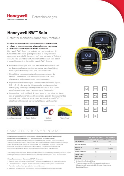
Detección de gasNOETOSO2H2NH3Cl2PH3HCNNO2C l O2H2S O2O3COFácil de manejar Fácil de leer Fácil demantenerFácil de verC A R AC T E RÍS T I C A S Y V E N TA J A SPara optimizar tiempos, incluyendo visibilidad remota de las alarmas,elija la versión inalámbrica. Y gestiónelo con su smartphone.Empareje el Honeywell BW™ Solo inalámbrico con nuestra aplicación móvil"Safety Communicator" y las lecturas del detector se enviarán instantáneamenteal software de supervisión en tiempo real de Honeywell. Acceda a él desdecualquier dispositivo mediante una conexión a Internet y obtenga unavisibilidad remota de la ubicación y la seguridad de los trabajadores.También puede utilizar el Honeywell BW™ Solo inalámbrico para compartir los datossobre gas con el software de escritorio; no requiere ninguna base de conexión.Otras funciones de Honeywell BW™ Solo son:• Opción para activar el IntelliFlash™ o la luz parpadeante de incumplimiento• La capacidad de asignar detectores a los trabajadores y a las ubicaciones• Pantalla fácil de leer que admite varios idiomas• Registro de datos con una lectura evolutiva de valor límite de 24 horasEl detector monogas de última generación que le ayudaa reducir el coste, garantizar el cumplimiento normativoy saber que sus trabajadores están protegidos.Honeywell BW™ Solo tiene todo lo que espera, además defunciones adicionales que lograrán que el cumplimientonormativo sea más fácil y más económico que nunca. Todo esocon una vida útil fiable, un funcionamiento con un solo botóny un perfil pequeño y ligero. Honeywell BW™ Solo es:• El detector monogas más fácil de mantener, sin necesidadde desmontarlo para sustituir sensores, baterías y filtros.Esto significa una larga vida y un coste reducido.• Complételo con una amplia selección de opciones desensor. Contará con una detección exhaustiva, tantosi supervisa peligros comunes como inusuales.CO, H2S y O2. Lo que significa una alta precisión, costesmás bajos y un tiempo de respuesta del sensor más rápidopara los gases que supervise con mayor frecuencia.• Compatible con IntelliDoX. Ahorre tiempo y centralice los datoscon pruebas funcionales, calibraciones y gestión de instrumentosautomáticas. Utilice las estaciones automáticas IntelliDoX conel software Honeywell Safety Suite Device Configurator.Honeywell BW™ SoloDetector monogas duradero y rentableBW™ SOLO Y BW™ SOLOWIRELESS DE HONEYWELLBW™ SOLO LITE*DE HONEYWELLTIPO DE SENSOR Serie 1**Serie 4REGISTRO DE DATOS Sí–REGISTRO DEEVENTOS50 eventos 5 eventosIDIOMAS ADMITIDOS115ASIGNACIÓN DETRABAJADOR YUBICACIÓNSí–* No disponible en América del Norte.** Póngase en contacto con el Servicio de atención al cliente o conel departamento de ventas regional de Honeywell Pregunte por ladisponibilidad al gestor.Honeywell BW™ SoloEspecificaciones técnicasDEBIDO A LA INVESTIGACIÓN CONTINUA Y A LAS MEJORAS CONSTANTES QUE SE APLICAN A LOS PRODUCTOS, LAS ESPECIFICACIONES ESTÁN SUJETAS A CAMBIOS SIN PREVIO AVISO.Datasheet_Honeywell BW Solo_DS110218-01_ES-ES | 11/18© 2018 Honeywell International Inc.* Solamente el Honeywell BW™ Solo Lite (no disponible en América del Norte).SISTEMA DE ACOPLAMIENTO INTELLIDOX IntelliDoX combina los módulos de acoplamiento inteligentes con nuestro sistema de gestión deinstrumentos para proporcionar pruebas automatizadasy facilitar la conservación de registros.Gestión de dispositivos con Honeywell Safety Suite/Safety SuitePara más información Honeywell HPPECra. 11a #98-50, Bogotá, ColombiaTamaulipas 141, 1° Piso, CDMX, México 06140Soporte al Cliente:e-mail:****************************。
霍尼韦尔氢气浓度检测仪IMPULSE-XP中文使用说明
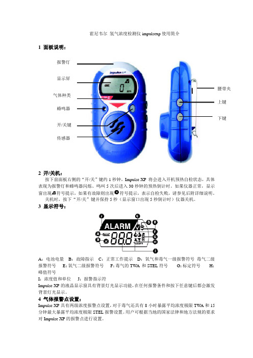
霍尼韦尔 氢气浓度检测仪impulsexp 使用简介1 面板说明:2 开/关机:按下前面板右侧的“开/关”键约1秒钟,Impulse XP 将会进入开机预热自检状态,具体表现为报警灯和蜂鸣器闪烁、鸣叫5次后进入30秒钟的预热倒计时。
如果仪器正常,显示窗出现符号提示,如果有故障则出现符号提示,表示自检失败,请参见后附详细说明。
关机时,按下“开/关”键并保持5秒(显示窗口出现5秒倒计时)仪器关机。
3 显示符号:A :电池电量B :故障指示C :正常工作提示D :氧气和毒气一级报警符号 毒气二级报警符号E :氧气二级报警符号F :毒气的TW A 和STEL 符号G :标定符号H :峰值符号I :浓度值和单位 J :报警指示符Impulse XP 的液晶显示窗具有背景灯光显示功能,在任何报警条件和按下任意键后都会激发背景灯光显示。
4 气体报警点设置:Impulse XP 具有两级浓度报警点设置,对于毒气还具有8小时暴露平均浓度极限TW A 和15分钟最大暴露平均浓度极限STEL 报警设置。
用户可根据当地的国家法律和地方法规的要求对Impulse XP 的报警点进行设置。
出厂设置如下:(英国标准)气体类型量程一级报警点二级报警点TWA报警点STEL报警点氧气0-30%vol 23.5%vol 19.5%vol ------- ------一氧化碳0-1000ppm 35ppm 100ppm 35ppm 400ppm 硫化氢0-250ppm 10ppm 15ppm 10ppm 15ppm 氢气0-1000ppm 100ppm 500ppm ------- ------ 二氧化氮0-150ppm 3ppm 5ppm 3ppm 5ppm 氯气0-50ppm 0.5ppm 1ppm 0.5ppm 1ppm 二氧化硫0-150ppm 2ppm 5ppm 2ppm 5ppm 氢氰酸0-100ppm 5ppm 10ppm 5ppm 10ppm 氨气0-100ppm 25ppm 50ppm 25ppm 35ppm 报警描述:报警类型显示声音报警灯光报警振动报警一级报警每秒3声每秒闪烁3次每秒两次二级报警每秒5声每秒闪烁5次每秒两次STEL报警每秒5声每秒闪烁5次每秒两次TW A报警每秒5声每秒闪烁5次每秒两次5 峰值,TWA和STEL显示模式:a. 正常显示b. TW A/STEL显示模式c. 峰值显示STEL模式TWA 模式如果想清除峰值,则在屏幕显示峰值时,按下“开/关”键一次,清除当前峰值并返回到正常的检测状态。
BW Clip 单气体探测器操作员手册说明书

零件编号 50115903-067 | OM-ZH-PALO-A 8 | BW Clip 操作员手册BW Clip 是一款由 BW Technologies by Honeywell (BW) 制造的便携式单气体探测器。
BW Clip 可以连续测量周边环境中某种特定气体的浓度,并在浓度超过报警设置点时激活警报。
您的责任是对警报作出正确回应。
BW Clip 是 GasAlert 产品系列中的一员。
它与 IntelliDoX 及 MicroDock II 自动测试和校准站兼容,也与 Fleet Manager II 软件 4.0 版或更高版本兼容。
有关更多信息,请访问产品网站,其网址为安全信息:请先阅读1.替代零部件可能会削弱仪器的本质安全性。
2.定期将探测器暴露于浓度超过低限报警设置点的目标气体中,以测试传感器的响应性能。
手动确认声音和视觉报警已启动。
3.处于休眠模式的探测器无法正常工作。
1.请在包装所示激活日期之前激活探测器。
2.本产品为气体探测器,非测量设备。
3.确保传感器护栅无灰尘、碎屑,且未堵塞。
4.使用柔软的湿布清洁仪器表面。
5.在不含危险 气体的正常空气中对探测器进行冲击测试。
6.为了达到最佳性能,请定期在不含危险气体的正常空气中 (20.9% v/v O 2)归零传感器。
BW Clip 工厂校准证书工厂已根据我们所注册的质量系统、操作标准及销售协议的条件和要求对该仪器进行过检查、测试和校准。
开始使用按键LED 可视警报和气体类型的气泡标签LCD和符号按键提示。
当显示此符号时,请按住按键不放直到此符号消失。
仅限于 O 2 型 BW Clip 。
氧气浓度将以体积百分比为单位进行测量。
仅限于 H 2S 、CO 和 SO 2 型 BW Clip 。
有毒气体浓度将以百万分率为单位进行测量。
低点警报和高点警报。
在探测到超过报警设置点的气体浓度时会显示 这些符号。
不合规警告。
此符号会在诊断或合规测试失败后显示;会在使用寿命倒计时到 24 小时或不足 24 小时后显示;并且在使用寿命到期后最多显示 30 天。
霍尼韦尔可燃气报警器说明书

霍尼韦尔可燃气报警器说明书一、技术指标感应气体:煤气、天然气、液化气电源:DC 12V直流电源或AC220V/50Hz家用电源工作环境:温度:-10℃~+40℃;相对湿度:≤90%RH声压范围:≥70dB/m报警浓度:15%LEL恢复浓度:8%LEL稳定性:长期工作报警浓度误差不大于±5%LEL重复性:重复测试报警浓度误差不大于±5%LEL报警浓度误差:不大于±5%LEL报警方式:声光报警,切断燃气阀与输出联网信号消耗功率:不大于5W注:标定气样为CH4气体二、安装位置:霍尼韦尔可燃气体报警器安装在距气源半径1.5m以内的合适位置。
若用于检测液化气时,因液化气比空气重,报警器须安装在高出地面0.3—1.0m处。
若用于检测天然气、煤气时,由于天然气、煤气比空气轻,报警器须安装在接近天花板0.3---1.0m处。
安装位置不要正处燃气灶上面,不要安放在排气扇、门窗边和浴室水汽较大处。
安装阀门控制器(1)将阀门控制器安装于球阀的上面,控制器的卡口卡住球阀的手柄,控制器的转动轴要与球阀的转动轴一致,使控制器与球阀的转动灵活,以免损坏控制器或球阀。
(2)用螺丝和固定板把控制器固定在燃气管道上。
(3)将阀门控制器安装在液化气瓶上。
(4)用连接线把可燃气体报警器和阀门控制器连接起来。
(5)红线为正极,黑线为负极,黄线为公共接点。
黄线与绿线为常闭接点,黄线与蓝线为常开接点。
三、工作、测试及维护程序将霍尼韦尔可燃气体探测器电源插头插入电源插座中。
(或接入12V DC电源,红线为正极,黑线为负极)。
通电后,探测器将会打开阀门,如阀门控制器损坏或没有装入阀门控制器,约15秒后,橙色指示灯点亮。
如果阀门控制器正常,橙色指示灯则不亮。
探测器在正常探测状态下,能自动检测到接入的阀门控制器,并将阀门打开。
此后探头进入预热状态,绿色发光二极管每秒闪烁一次,约三分钟后,蜂鸣器发出“嘀—”的一声,电路进入稳定的工作状态。
霍尼伟尔气体侦测器中文说明书
HoneywellAnalytics©2004 Honeywell Analytics Issue 1 12/2004 MIDAS-A-001目录1 目录 22 概述 53 产品概述 5 3.1 主机架 6 3.1.1 显示器模块 63.1.2 泵模块 7 3.1.3 传感器暗盒腔 73.2 安装托架底座 73.2.1 安装托架 73.2.2 终端模块 73.3 传感器盒 83.3.1 偏致传感器盒 83.4 机壳 84 默认配置 95 安装95.1 探测器的安装和定位 105.2 机械安装 115.3 样品和排气管道计算 125.4 在线过滤器 135.5 本地化探测器选购件 145.6 电气安装 155.7 电连接 17 5.8 改装主机架 185.9 安装传感器盒 196 探测器启动程序 197 总体操作 21 7.1 正常操作模式 217.1.1 重置报警、故障和维护故障 227.2 浏览模式 227.2.1 浏览模式菜单概述 237.3 设置、校准和测试模式概述 247.3.1 设置菜单概述 247.3.2 校准菜单概述‘CAL’ 267.3.3 测试菜单概述‘ tESt’ 278浏览、设置、校准和测试模式子菜单的导向的详细程序 288.1 浏览模式 288.1.1 复查软件‘SW’ 288.1.2 复查报警‘ ALm’ 298.1.3 复查故障‘ FLt’ 298.1.4 复查校准 ‘ CAL’ 298.1.5 复查日期和时间‘timE’ 298.1.6 复查探测器地址‘ nEt’ 308.1.7 复查事件标识‘ Hi St’ 308.2 设置、校准和测试模式 308.2.1 设置菜单‘ SEt’ 318.2.2 设置报警‘ ALm’ 318.2.3 设置故障‘ FLt’ 348.2.4 设置校准间距 ‘ CAL’ 348.2.5 设置日期和时间 ‘timE’ 558.2.6 设置地址‘ nEt’ 358.2.7 设置密码 ‘ PWd’ 368.3 校准菜单‘CAL’ 368.3.1 零点校准 ‘ 0CAL’ 368.3.2 间距校准‘ SPAn’ 378.3.3 流量校准‘ FLoW’ 388.3.4 mA 校准 ‘mA 4-20’ 388.4 测试菜单‘ tESt’ 398.4.1 颠簸测试 ‘ bUmP’ 398.4.2 报警/故障测试‘ Si m’ 398.4.3 禁止状态‘ I nH’ 409 常规维护 41 9.1 传感器盒的更换 419.1.1 传感器盒的安装/更换 419.2 泵的更换 43 9.3 重新组装探测器 469.4 过滤器的更换 4610 热解器模块选项 4710.1 安装热解器模块 4810.2 重新组装MIDAS® 探测器 4911 模拟输出模块 51 11.1 安装模拟模块 5111.2 重新组装MIDAS® 探测器 5212 找出故障并诊断 5313 REFLEX®ٛ5414 内置的网络服务器 5414.1 物理的网络组件 5414.2 网络设置 5414.3 运行网络浏览器 5415 典型安装拓扑 5615.1 常规安装 57 15.2 Modbus/TCP 安装 5715.3 通过以太网供电(POE) 的安装 5716 订购信息 58 16.1 MIDAS® 发送器 5816.2 MIDAS®热解器 5816.2 MIDAS® 热解器 5816.3 MIDAS® 模拟输出模块5816.4 MIDAS®插入式传感器盒(标准保修期) 5916.5 MIDAS®插入式传感器盒(延长保修期)6016.6 完整的MIDAS®气体探测器套件 6116.7 附件及备件 6117 一般规格 6218 校准及颠簸测试 6319 保证声明6720 软件菜单叙述图表 6920.1 高级6920.2 浏览模式7020.3 复查软件的信息、报警、故障及气体校准7120.4 复查日期/时间和网络7220.5 复查事件日志7320.6 设置模式7420.7 设置报警、故障及气体校准 7520.8 设置日期/时间和网络7620.9 设置密码7720.10 校准模式7820.11 校准气体零点及间距7920.12 校准——流量校准 8020.13 校准——4-20 mA 8120.14 测试模式8220.15 测试颠簸、报警/故障模拟 8320.16 测试禁止8421 联系详情 852 概述作为一个提取式气体取样系统,MIDAS气体探测器能在本地或从一个远程点提取一个样品到位于探测器机架内的传感器盒。
气体检测仪说明书- Honeywell Analytics 气体检测仪说明书- GasAlertMi

H2S, CO, O2, LELMulti-gas made simpleThe easy to wear, slim and compact GasAlertMicroClip providesaffordable protection from atmospheric gas hazards and extendedbattery life, especially in cold weather. The GasAlertMicroClip featuresvisual compliance at a glance with the flashing, green IntelliFlash™. Easyone-button operation reduces training time and lets workers focus onthe job at hand. For simple, cost-effective management of your records,calibration and bump testing, choose BW’s MicroDock II automatic testand calibration system and Fleet Manager II software.Meets ACGIH 1 ppm H2S TWA recommendations.Visit to download the latest Fleet Manager IIupdate.Standard Package Contents• Detector complete with specified sensor(s), stainless steel alligator clipand concussion-proof housing• Rechargeable battery• Wall outlet charging adaptor• Calibration/test cap and hose• Manual• Multi-language CD manualGeneral SpecificationsGasAlertMicroClip XL GasAlertMicroClip X3Size 4.4 x 2.4 x 1.2 in. /11.3 x 6.0 x 3.1 cm 4.4 x 2.4 x 1.2 in. / 11.3 x 6.0 x 3.1 cmWeight 6.7 oz. / 190 g 6.3 oz. / 179 g Temperature-4 to +122°F / -20 to +50°CTypical battery life18 hours (recharges in less than 6 hours)Note: Battery is guaranteed to have 12 hour runtime during warranty periodunder normal operating temperature of 4°F / -20°C to 122°F / 50°C. Ingress Protection IP68Certifications andapprovals n Class I, Div. 1, Gr. A, B, C, DATEX:X g II 1 GEx ia IIC T4 GaIECEx:Ex ia IIC T4 GaX: European ConformityWarranty Full two-year (GasAlertMicroClip XL) orthree-year (GasAlertMicroClip X3) warranty including all sensorsOrder NumberGasAlertMicroClip 4-Gas Detector GasAlertMicroClip XL GasAlertMicroClip X3GasAlertMicroClip 3-Gas Detector GasAlertMicroClip XL GasAlertMicroClip X3GasAlertMicroClip 2-Gas Detector GasAlertMicroClip XL GasAlertMicroClip X3GasAlertMicroClip 1-Gas Detector GasAlertMicroClip XL GasAlertMicroClip X3Note: To order a unit with black housing, change order number component "-Y-" to "-B-".GasAlertMicroClip Region CodesGas LegendMicroDock IIAutomatic test and calibrationstation (see MicroDock II sectionfor additional information)Confined Space KitOrder NumberCarrying & Protective Accessories Order NumberSampling & Testing EquipmentOrder NumberNote: For complete list of Sampling & Testing Equipment, please refer to the full Price List or contact Honeywell Analytics.Power Options and Spares Order Number *For regions outside North America replace “-NA” with: “-EU” for Europe, “-UK” for United Kingdom and “-AU” for Australia/China.Deluxe Confined Space KitMC-CK-DLOrder detector and calibration gas separately.Test CapMC-TC-1Auxiliary Filter KitMC-AF-K1Easily attaches in the fieldto protect the internal filterManual Aspirator Pump KitMC-AS01For remote sampling; complete with probe,hose, aspirator pump and adaptor capBlack Leather PVC CaseMC2-LC-1Datalogging AccessoriesOrder NumberMicroDock IIOrder NumberReplacement Sensor ScreensOrder NumberReplacement SensorsOrder NumberFor a full list of calibration and testing equipment, please refer to the full Price List or contact Honeywell Analytics.IR Connectivity KitGA-USB1-IRUse for data download andinstrument set-up optionsVehicle Power Adaptor 12-24 V dcGA-VPA-1Direct-Wire Power Adaptor 12-24 V dcGA-PA-3Multi-Unit Power AdaptorGA-PA-1-MC5-NA*Simultaneously charges five detectorsMulti-Unit Cradle ChargerMC2-C01-MC5Simultaneously charges five detectorsNote: Please refer to the instrument’s documentation (shipped with the product or available at ) for complete instructions on common service procedures. Improper servicing or maintenance may affect warranty eligibility. Honeywell assumes no liability for damages resulting from improper servicing or maintenance.LegendService PartsOrder Number Note: Please refer to the instrument’s documentation (shipped with the product or available at ) for complete instructions on common service procedures. Improper servicing or maintenance may affect warranty eligibility. Honeywell assumes no liability for damages resulting from improper servicing or maintenance.How to Replace a Sensor1. With detector OFF , use No. 1 Phillips screwdriver to remove 6screws from back enclosure (E)2. Lift back enclosure (E) straight up3. Use No. 1 Phillips screwdriver to remove 2 screws from backof PCB (D)4. Lift PCB (D) together with battery and sensors (C, G, H, I)straight up5. Remove sensors (C, G, or H) by sliding out or sensor (I) bypulling straight up from PCB (D)6. Insert new sensor (C, G, H, I) into PCB (D)7. Replace PCB (D) and 2 screws and hand-tighten until firm 8. Replace back enclosure (E)9. Replace 6 screws in back enclosure (E) andhand-tighten until firmHow to Replace the Sensor Screen1. With detector OFF , use No. 1 Phillips screwdriver to remove 6screws from back enclosure (E)2. Lift back enclosure (E) straight up3. Use No. 1 Phillips screwdriver to remove 2 screws from backof PCB (D)4. Lift PCB (D) together with battery and sensors (C, G, H, I)straight up5. Remove sensor screen (J) from front enclosure (B)6. Insert new sensor screen (J) into front enclosure (B)7. Replace PCB (D) and 2 screws and hand-tighten until firm 8. Replace back enclosure (E)9. Replace 6 screws in back enclosure (E) andhand-tighten until firm。
霍尼韦尔 侦测污染气体的指南书 ( 空气质量监测系统指南书 )说明书

This step-by-step guide describes set-up procedures to help provide a safe parking garage while minimizing energy costs associated with ventilation and heating.2In parking structures, CO and NO 2 are two of the most abundant airborne contaminants and poses significantsafety concerns. The CO and NO 2 levels must be controlled or ventilated when concentrations approach unsafe levels.Various gas monitors are available for use in parking structureapplications. The specifics of the design determine what type of monitor or monitoring system best suits the application. This detailed, easy-to-use guideline assists the design engineer in the selection of an optimal gas detection solution.Codes and StandardsStep 1: Determine the reason(s) why you want to detect the presence of carbon monoxide.• Safety: In any facility where people are working or the public and tenants may be active, there must be due diligence on the part of the owner to assure a safe breathing environment.• Economics: To provide fresh air in a facility where vehicles are present, a pre-determined air change per hour is required. This can be expensive for a number of reasons:1) The electrical energy required to run the fans can be high.2) The fans run continuously which incurs wear and shortens motor life.3) The frequency of required maintenance is higher for belt and lubrication services.4) The heat loss in a garage is higher with the high volume of air changes.• Aesthetics: In private facilities, the outside fan noise and loss of heat within the garage can affect tenant satisfaction.Step 3 : Building codes and carbon monoxide monitoring• International Mechanical Code - Section 403.5 Public garages - Mechanical ventilation systems for public garages are not required to operate continuously where the system is arranged to operate automatically upon detection of a concentration of carbon monoxide of 25 ppm by approved detection devices.• Uniform Building Code - Section 705 - In allparking garages…automatic CO sensing devices may be employed to modulate the ventilation system to maintain a maximum average of CO of 50 ppm during any eight-hour period, with a maximum average concentration not greater 200 ppm for a period not exceeding one hour…• State, municipal and other building codes - Most state, and local municipal buildingcodes recognize and recommend using carbon monoxide monitors in enclosed parking garages. If the building code in your area does not have any provisions for CO monitoring, do not forget that carbon monoxide is still a very dangerous gas to personal health and safety. Therefore, the use of common sense by design engineers is still the best “building code” to use.Step 2 : What the ASHRAE handbook says about carbon monoxide detection in parking garages:• “The operation of automobiles presents two concerns. The most serious is the emission of carbon monoxide, with its own risks.”• “The second concern is the presence of oil and gasoline fumes…the ventilation required to dilute carbon monoxide to acceptable levels will also control the other contaminants satisfactorily.”• “To conserve energy, fan systems should be controlled by carbon monoxide meters with multiple fan or variable speed stages for larger systems, if permitted by local codes. In multi-level parking garages or single-level structures of extensive area, independent fan systems, each under individual control, are recommended.”• “The ventilation system in parking garages, in general, moves large quantities of air throughlarge openings without extensive ductwork. These conditions, in addition to the highly reverberant nature of the space, contribute to high noiselevels.”The 301C is able to monitor up to 96 hardwired transmitters and has a series of relays which can activate alarms and/or ventilation equipment as required.• Carbon monoxide poisoning is a form of asphyxiation. Carbon monoxide combines with hemoglobin, the oxygen-carrying constituent of blood, 210 times more readily than does oxygen. Carboxyhemoglobin is then formed. Carbon monoxide lowers the oxygen carrying capacity of blood and interferes with necessary gaseous exchange functions.• Human health effects can vary significantly based on overall state of health, sex, age and weight.• Many studies have shown that the CO content in exhaust gases of individual vehicles varies greatly. This variation is caused by such factors as the age of the vehicle, carburetor adjustment or injector condition, quality of fuel, engine horsepower, level of maintenance, and differing driving habits of motorists.• Levels of carbon monoxide in garages vary depending on:1) Number of cars running2) Length of travel and operation time of cars in the garage3) Emission rate of vehicle4) Acceptable contaminant level within a given facility Sequence of OperationStep 5: Carbon monoxide alarm levels andrecommended sequence of operation• First alarm level:1) Set at low concentration. See Table 2 forrecommended low alarm level).2) Gas monitoring system shall be able to actuateexhaust fans and outside air intake devices tobring the carbon monoxide level down to anacceptable level.3) Optional: if the parking structure is equippedwith either two-speed fans or with a second setof fans, only the first speed of fans or the first setof fans should be actuated.• Second alarm level:1) Set at high concentration. See Table 2 forrecommended high alarm level).2) Ventilation equipment previously actuatedat low level in the parking garage shall remainoperational.3) Optional: if the parking structure is equippedwith either two-speed fans or with a second setof fans, they should be activated at full speed orall fans should be activated.4) Activation of strobe light (red) and horn mightbe required.5) People might be required to evacuate theparking garage.The E3Point utilizes cutting edge technology in orderto accurately and reliably monitor carbon monoxideand Nitrogen Dioxide (diesel fumes) levels.Step 7: Interlock of the mechanical ventilation with the carbon monoxide monitoring systemThe CO monitoring system shall activate the mechanical ventilation by using either:• Dry contacts through magnetic starters• Dry contacts through motor control center (MCC)• Dry contacts and/or analog outputs (4-20 mA) through the Building Management System (BMS)• Analog outputs (4-20 mA) modulating the speed of the fans through variable frequency drives (VFD)The carbon monoxide monitoring system must be capable of activating both the exhaust fan(s) and the air intake device(s) such as outside air louvers/ dampers and make up air unitsEquipment Selection and Location: Central Panel and Output ModuleStep 8: Monitoring System Selection• Stand-alone monitors: These are usually single points for smaller applications (small number of monitoring points). They are real-time reading with a limited amount of outputs and no moving parts (less maintenance).• Network monitoring system: These are for multiple sensing points usually being largerapplications. They are real-time reading withseveral programmable outputs and no movingparts (less maintenance)Step 9: Gas detection central panel and relaymodule• Must be located out of reach of the generalpublic.• Preferably located inside or close to the motorcontrol center or in connecting offices.• The controller shall allow programmable alarmlevels through relays.• Addressable transmitters are daisy-chainedthrough a RS-485 communication protocol to thecontroller.• The controller module and programming shouldbe accessible only by using the proper password.• Shall be capable of averaging / zoning.• Optional 4-20mA / digital input card to allow fan’scurrent sensor to be connected to the controller.Step 10: Self-test diagnostics withmalfunction warning• Not all monitors on the market offer thesefeatures.• These features insure protection at all times.• Checks operating status of the monitor itself.Step 11: Output signals• Alarm relay output: At least two are required (lowand high levels).• Failure relay output: Only one is required (indicatemonitor failure).• Analog output: provides one 4-20 mAper output sensor or provides the highestconcentration, the lowest concentration or theaverage concentration of CO for a group ofsensors (normally interlocked with The BuildingManagement System).Step 13: Quantity of sensors and plan locationThe quantity of sensors is determined by the following rules of thumb:1) The radius of coverage is 15.2 m (50 feet) per carbon monoxide monitor or 2,310 sq.m (7,580 sq.ft).2) Use open interior support columns as much as possible to maximize the radius of coverage not walls.3) Each level of the parking structure must be totally covered without overlapping the coverageof the sensors. See Figure 2.Step 14: Height of sensorsThe relative density of carbon monoxide compared to air of carbon monoxide is 0.957 (AIR =1). The carbon monoxide will disperse evenly in the air. The carbon monoxide monitors must be located as specified by your region’s building code. If not specified contact your local Honeywell Analytics representative.AccessoriesStep 15: Audible and visual alarm devices • In general, the mechanical ventilation should be able to evacuate the carbon monoxide out of the parking structure fast enough to maintain the level below 200 ppm. The following are examples where the carbon monoxide level may reach concentrations above 200 ppm:1) Retrofit of a garage where the ventilation system is not adequate2) During a major event such as a sporting event or concert where people are leaving the parking garage within a very short period of time 3) Some local codes don’t allow carbon monoxide concentrations above 100 ppm. It might be difficult even for the best mechanical ventilation systems to keep the level that low.• For all of the above mentioned reasons, an audible and/or visual alarm might be required to notify the proper personnel to take corrective actions including possibly evacuating the parking structure.• Audible and visual alarm devices must beinstalled in a way to warn workers about high CO levels• Among the best suitable places for alarm devices are ticket booths and parking garage supervisor/operator offices • The selection depends on the type of facility and the purpose of the alarm.Visual1) Flashing beacons (stackable beacons can be used when multiple visual alarms are required)2) The recommended status mode colors for beacons (stackable or individual) include: Blue: Carbon monoxide monitoring system malfunctionAmber: Low carbon monoxide concentration Red: High carbon monoxide concentration Audible3) The sound level should vary depending on the location of the audible alarm and its purpose 4) The audible alarm can be integrated with the beacons or remote annunciators or can be separateStep 16: Warning signs• Warning signs should clearly identify the meaning of all system status from visual and audible alarm devices.• Warning signs should be located close to every alarm devices.• The signs should be at least 40 cm square (16 in. square).• Black engraved letters on white bond.Step 17: Special environment and accessories Depending on the parking structures, special requirements may include:• Nema 4X enclosures: essential when sensors are exposed to dust, dirt, light splashing.( “X” designates resistance to corrosive agents.)• Splash Guard: (ECLAB) Provides enhancedprotection from water hose spray (when washing cars or parking garage walls).• Low temperature assembly: special treatment should be applied to the electronic component of the sensors to insure proper functioning of the unit even at low temperature (rated to -20º Celsius or -4º Fahrenheit).Closeout ProceduresStep 18: Start-up and commissioningEngage a factory-authorized service representative to perform the following:1) Inspect field-assembled components,equipment installation, and electrical connections for compliance with requirements.2) Test alarm set points of the carbon monoxide monitoring system with calibration gases and verify sequence of operation.3) Prepare a written report to record testprocedures, test results and corrective actions if required.4) Report should also cover the requirements for accessories like adequacy of alarm types, signs and protective equipment.5) Repair or replacement of malfunctioning units should be performed at the manufacturer’s factory.Step 19: Demonstration and TrainingUtilize a factory-authorized service representative to train owner’s maintenance personnel to adjust, operate, trouble shoot, calibrate and maintain the carbon monoxide monitoring system.Step 20: Calibration1) Calibration intervals must comply with manufacturer’s recommendations.2) Calibration kits should be provided at the date of delivery of the gas detection system.3) Owner may consider using factory-authorized service representative to maintain and calibrate the gas monitoring system periodically.Energy Savings AnalysisStep 21: Energy saving calculations — electrical fan motorsThe capital and operating cost of a carbon monoxide monitoring system versus the energy and maintenance of running the ventilation at higher volumes can be an important decision factor. Time of Day Fan SchedulingSome manufacturers are offering a time switch in their CO monitoring system or some designs are actuating the ventilation system based on the time of the day even if the garage is equipped with a CO monitoring system.• The CO monitoring system is detecting the presence of CO and is actuating ONLY when needed • Many of the benefits of a CO monitoring system are defeated by over-riding it with a time switch. Diesel Exhaust MonitoringNitrogen dioxide (NO 2) is the major contaminant to be considered in the design of a ventilation system when diesel-powered vehicles will be present.• Detection of nitrogen dioxide is done where a significant quantity of diesel engines typically are located such as train stations, bus and truck maintenance garages, rapid transit authorities, car dealerships, ambulance bays, loading docks and diesel-powered vehicle parking structures.APN069_v5 1/15© 2015 Honeywell AnalyticsH W A 6086Honeywell Analytics Lines of Business。
Honeywell Searchline Excel Plus 气体检测仪说明书
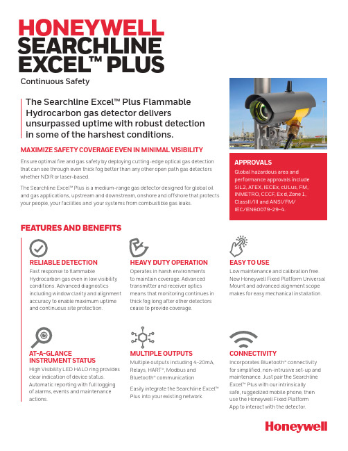
HONEYWELL SEARCHLINE EXCEL™ PLUS Continuous SafetyFEATURES AND BENEFITSRELIABLE DETECTIONFast response to flammable Hydrocarbon gas even in low visibility conditions. Advanced diagnostics including window clarity and alignment accuracy to enable maximum uptime and continuous site protection.HEAVY DUTY OPERATION Operates in harsh environmentsto maintain coverage. Advanced transmitter and receiver optics means that monitoring continues in thick fog long after other detectors cease to provide coverage.AT-A-GLANCE INSTRUMENT STATUSHigh Visibility LED HALO ring provides clear indication of device status. Automatic reporting with full logging of alarms, events and maintenance actions.EASY TO USELow maintenance and calibration free.New Honeywell Fixed Platform UniversalMount and advanced alignment scopemakes for easy mechanical installation. MULTIPLE OUTPUTSMultiple outputs including 4-20mA,Relays, HART®, Modbus andBluetooth® communicationEasily integrate the Searchline Excel™Plus into your existing network.APPROVALSGlobal hazardous area andperformance approvals includeSIL2, ATEX, IECEx, cULus, FM,INMETRO, CCCF, Ex d, Zone 1,ClassII/III and ANSI/FM/IEC/EN60079-29-4.The Searchline Excel™ Plus FlammableHydrocarbon gas detector deliversunsurpassed uptime with robust detectionin some of the harshest conditions.MAXIMIZE SAFETY COVERAGE EVEN IN MINIMAL VISIBILITYEnsure optimal fire and gas safety by deploying cutting-edge optical gas detectionthat can see through even thick fog better than any other open path gas detectorswhether NDIR or laser-based.The Searchline Excel™ Plus is a medium-range gas detector designed for global oiland gas applications, upstream and downstream, onshore and offshore that protectsyour people, your facilities and your systems from combustible gas leaks.CONNECTIVITYIncorporates Bluetooth® connectivityfor simplified, non-intrusive set-up andmaintenance. Just pair the SearchlineExcel™ Plus with our intrinsicallysafe, ruggedized mobile phone; thenuse the Honeywell Fixed PlatformApp to interact with the detector.Honeywell Searchline Excel TM Plus T echnical SpecificationsSee product manual for full specifications.Honeywell Searchline Excel TM Plus Accessories, Spares and System Part Numbers*******************。
Honeywell Vertex Gas Monitoring System用户手册说明书

MUL TI-POINT TOXIC GAS2 | | Honeywell Vertex™ Gas Monitoring SystemVertex™ – the highly sensitive and reliable multi-point low-level toxic gas monitoring system backed by physical evidence of an actual gas release.VERTEX OFFERS A GAS MONITORING SOLUTION THAT ADAPTS TO YOUR CHANGING GAS DETECTION NEEDSAccuracyThe Vertex provides various benefits, including improved accuracy and safetythrough well-defined visual staining even at low concentrations detection enabled by Honeywell’s flow-through closed-loop optical system. This feature enhances the system’s ability to detect toxic gases, leading to a more efficient, safer operation and helps to minimize downtime.Enhanced safety and operational efficiencyThe Vertex’s full suite of redundancy features advanced communications that mitigate the risk of system failure, such as • Dual power supply • Dual hard drives • Dual pumpsSupport continuous operation even in the event of system continuity issues, promoting enhanced safety and improved operational efficiency.Reduced total cost of ownershipVertex provides a reduced total cost of ownership through automatic flow adjustments, which reduces the time required for servicing and maintenance. Advanced diagnostics include 100+ instrument and maintenance faults to advise the user of the system’s operational stateACCURATE, CONTINUOUS MUL TI-POINT DETECTION OF TOXIC GASES AT A HIGH LEVEL OF RELIABILITYVertex™ offers powerful,built-in system redundancyas standard equipment toeffectively safeguard againstdowntime.Honeywell Vertex™ Gas Monitoring System | | 34 | | Honeywell Vertex™ Gas Monitoring SystemAs the pioneer of Chemcassette® gas analyzers, we engineered the Vertex to deliver an increased level of reliability.A CLEARL Y VISIBLE STAIN FOR LOW-LEVEL DETECTION YOU CAN COUNT ONWith Honeywell Chemcassette technology, the density of the stain on the tape is proportional to the concentration of the gas, so visibility of the stain is critical. That’s why Honeywell Vertex tape-based systems, generates a clear, easy-to-view stain that matches the severity of the gas release. With this precision, the opticalscanners in Vertex can measure the stain accurately and trigger the right alarm.ReliableVertex offers powerful, built-in system redundancy as standard equipment to effectively safeguard against downtime.• Back-up pump and internalpower module• Chemcassette technology provides physical evidence of a gas event• System data backup. If main data acquisition PC fails, analyzerscontinue to monitor, log data andalarm• Drip-resistant cap for systemprotection from overhead leaks• Automated leak test with lineintegrity optionFlexibleStart your Vertex system with as littleas eight points. Vertex expands as your monitoring needs change, offering up to 72 points of continuous gas detection. Place sampling points up to 400 feet (120 meters) from the system. There is a choice of universal analyzer modules and/or pyrolyzer analyzers.Easy to use• Touchscreen for easy access to data • Software updates via CD-ROM or network to all system components • Configuration profile editing and dataretrieval are all achievable withouttaking unit offline• Radio frequency identificationtag (RFID) ensures Chemcassetteare installed into appropriatelyprogrammed analyzer, eliminatinghuman error• Online help systemSecurity• Multiple levels of password protection• Reconfigure security setup withouttaking unit offlineReduced total cost of ownership• Vertex’s smaller footprint and greaterdensity of points reduces your costper point• Eight points per analyzer lowersChemcassette costs• Maximized 72-point systems providelow cost per point as compared toother continuous monitors• One system monitors up to nine gasfamilies and more than 40 gases• You can split your sample into morethan one analyzerEasy to maintain• Vertex uses cost-effective XPChemcassettes providing up to fourmonths of continuous monitoring• Simplified replacement ofChemcassettes and automated opticsverification• No dynamic calibration required• Easy access to analyzers, pumps,power supplies and touchscreen fromfront panel• Onscreen interactiveelectronic manualAdvanced communications• Built-in configurable PLCs withoptional 176 relay contacts• Standard OPC interface for easyintegration into your existing factoryautomation system or HMI• Optional Ethernet/CIP, DeviceNet™,Profibus®, Profinet®, Modbus/TCP orControlNet™ outputs available• Optional ChemCam camera permitsviewing of stain, locally or remotely,for proof of the gas event. Image iselectronically saved for future retrieval.• Optional remote control/viewingsoftware enables total visualization ofthe monitor screens at a remote PCOperating system• Windows® 10 IoT Enterprise to improveIT securityFEATURES AND BENEFITSHoneywell Vertex™ Gas Monitoring System | | 5DESIGNED FOR THE TOXIC GASES IN YOUR OPERATIONSHoneywell Vertex can be tailored to meet the requirements of your facility. With up to nine Chemcassette gas analyzers, each with eight points of detection, the system monitors virtually every gas used in semiconductor fabs — down to parts per billion (ppb). These gases include:• Chemcam Camera• Line Filters• TubingDESIGNED FOR THE TOXIC GASES INYOUROPERATIONSNew calibrations are continuously developed.6 | | Honeywell Vertex™ Gas Monitoring SystemHoneywell Vertex™ Gas Monitoring System | | 7RELIABILITY AND DURABLE SUPPORTHoneywell is a major gas detection provider with a division focused exclusively on semiconductor manufacturing and other high tech industries such as solar material, flat panel displays and more. That means we know your business — and how you need to protect it.At Honeywell, we understand the value of your production. That’s why we engineered the Honeywell Vertex for an enhanced standard of accuracy and reliability, so you can feel confident that your toxic gas management system is helping to keep your people safe and your operations running.Every day, Honeywell gas detection technologies protect people and billions of dollars in assets at semiconductor fabs, research labs and other high tech facilities throughout the world. And since we are the original manufacturer of the Vertexproduct lines we sell, we know how to support it. Honeywell has a worldwide network of service engineers who are knowledgeable and passionate about gas detection.Honeywell Vertex is part of a comprehensive ecosystem of gas-detection products and services for your operations, including fixed systems, portable and transportable gas detectors, controllers, software, systems integration and more. So when you demand enhanced safety standards and deep knowledge of industrial technologyand applications, Honeywell is here for you.WORLD LEADER IN GAS DETECTIONHoneywell Analytics offers you more than 30 years’ experience in developing patented Chemcassette® tape technology. Vertex™ Multi-Point Toxic Gas Monitoring System complements electrochemical cell, catalytic bead and infrared monitors.24 HOUR SERVICEHoneywell’s global team oftechnical service professionals is at your service 24 hours a day, 7 days a week in more than 60 countries.For more informationHoneywell Sensing and Safety Technologies830 East Arapaho Road Richardson, TX 75081 Contact usUS & CanadaTel. 302 613 4491***************************HGAS_Vertex™_BRO_US-EN_0323©2023 Honeywell International Inc.Profibus and Profinet are trademarks or registered trademarks of Profinet International (PI).DeviceNet and ControlNet are trademarks or registered trademarks of ODVA, Inc.Windows is a trademark or registered trademark of Microsoft Corporation in the United States and other countries.Vertex and Chemcassette are trademarks or registered trademarks of Honeywell International Inc.。
Honeywell iSeries 智能气体传感器诊断测试说明书

DIAGNOSTIC TESTS FOR THE INTELLIGENT GAS SENSORS, iSERIESTechnical NoteHoneywell introduces the Next-Generationintelligent (iseries) gas sensors. These sensorshave a digital interface, longer life andnumerous built-in diagnostics features.The iseries’ intelligent diagnostic features help enhance the overall instrumentperformance, making them smarter and safer by indicating faults and monitoringhealth, thereby decreasing downtime and cost of ownership.The purpose of this document is to describe the Predictive Calibration and End-of-lifefunctions, and outline the principles of the diagnostic tests.BACKGROUNDAll gas sensors drift over time and eventually need recalibrating, and the amountof drift is strongly dependent on the environment that the sensor is used in.Traditionally, instrument developers, fleet managers or end users would work out forthemselves by experience how often they need to recalibrate sensors, or would use recommendations from the sensor or instrument manufacturer as it is not knownwhat conditions the sensors are being used in. This often results in unnecessarilyfrequent recalibrations which is costly and time consuming.Intelligent FeaturesThe iseries platform uses internal tests to monitor the condition of the sensorand apply algorithms both to compensate for drift and to predict when the sensoraccuracy exceeds a predefined limit and needs recalibrating.It can also predict when it is wearing out and can give warning in advance that thesensor needs replacing. As both the Predictive Calibration and End-of-life indicationuse predictions based on the environment that the sensor is being used.Definition of Diagnostic TestsPredictive Calibration: The calibration process can be very tedious, costly and a time-consuming process. With this function, sensors can predict in advance whenits accuracy is becoming too poor to give a reliable reading. This function helps to identify exactly when a recalibration is required.The sensor can estimate the time to recalibration up to six months in advance. Recalibration intervals will be typically at least twice as long as for conventional sensors and will adapt depending on the environment – with sensors used in more benign environments needing less frequent calibrations than those in aggressive ones.The user can configure the accuracy limit of the sensor, and this will determine the interval at which the calibration is needed. In other words, the tighter the accuracy value, the more frequent calibration needed.The user can therefore trade off accuracy against recalibration interval. There is also a configurable built in fixed interval recalibration countdown timer for applications where legislation requires calibration at certain intervals.End-of-Life: The lifespan of a sensor depends mostly on the environmental conditions at which the sensor is exposed. With this function, the sensor can predict in advance when its sensitivity is falling too low to give a reliable and accurate reading. When the End-of-life function is triggered, the sensor automatically warns the instrument via a set of fault flags sent together with the gas reading. If the fault is detected the instrument can warn the user to stop using the sensor.How was the design of the sensor optimised?Honeywell engineers performed finite element analysis of the water management and electrolyte distribution within sensors and gained an extensive understandingof the optimum designs for retaining the electrolyte in the right place at the right concentration.Subsequently, safety operating area charts were developed based on a combination of fundamental physical theory, modelling and experimental verification to show how sensors will perform and withstand over the full temperature, humidity and time.To validate that the sensor will last in real-world applications, an environmental database was obtained. The database contains hundreds of locations around the world, with temperature and humidity data for 10 years with two hourly resolution. The knowledge of use cases for sensors was combined, for example time spent indoors and outdoors, charging to provide input data on the actual conditionssensors are exposed to in the real world. This information was fed into the models to predict how long sensors will last and how their performance will change in real world conditions, and to assist us in optimising the sensor design for maximum performance and life.The environmental performance data was generated by storing sensors in a rangeof environmental conditions over a two-year period. There were more than 8000 individual gas responses recorded for each gas typeDuring this period, the sensors were tested to generate different databases corresponding to the performance of the sensor at particular environments.The resulting predictive algorithm keeps track of the electrolyte concentration and environmental conditions over time and extrapolates this data with a linear regression in order to accurately predict when does the sensor need to be calibrated or when does the sensor is about to reach its lifespan.How does the predictive model for EoL and Predictive Calibration works?To estimate the EoL and Predictive Calibration, a 30-day time period is defined. During this period, the sensor will keep track of the environmental changes. The model works under the assumption that the sensor will be exposed to similar conditions.For instance, if the sensor has been in an extremely hot and dry environment, the predicted model will calculate the corresponding water loss as if the conditions remained the same; giving warning to the user in order to prevent further dry out. Figure 1 shows how the electrolyte concentration and predicted electrolyte concentration vary for a sensor in an extreme environment. The environment chosen corresponds to a challenging environment for the sensor to survive: during winter, outdoor temperatures can be -40°C or less, and in a heated unhumidified buildingor car, the relative humidity can be extremely low due to the very low water content of the cold outside air. Therefore, a sensor which spends part of the day indoors and part outdoors (a typical ‘field worker’ use case) not only gets very dry in winter but is also expected to function at very low temperatures.A perfect prediction (theoretical) would follow the dashed black line. In other words, the predicted days to recalibration would be exactly equal to the actual days to recalibration.The solid black line shows the true electrolyte concentration, which gets dry (high concentration) each winter but recovers to some extent each summer. The yellow line shows how the concentration has been predicted. The historical relative humidityis calculated from the average of another 30 days prior to that. As the prediction is made over a longer time, it becomes less accurate, mainly because the historical environmental conditions become less representative of the future conditions. How often does the sensor updates the EoL and Predictive Calibration?The diagnostic test runs automatically every 24 hours. However, the test is only performed when the sensor is in sleep mode, so it is highly recommended to change the sensor to sleep mode whenever it is not in use (otherwise the End of Life and Predictive Calibration estimations will not be updated/recalculated, leading to non-accurate results).The sensor needs to be in sleep mode at least two minutes per day, so it can update the EoL and Predictive Calibration values.What technique is used for the diagnostic tests?For this test, a smart indicative gadget is used as a diagnostic electrode. Thenan electrochemical technique called square wave voltammetry is applied to the electrode.The technique is a linear potential sweep voltammetry that uses a combined staircase potential and a square wave, which has the advantage of having better peak definition and location than conventional cyclic voltammetry or staircase voltammetry.The diagnostic test is performed to determine the electrolyte concentration of the sensor.Figure 2. Diagnostic TestingHow and when the End-of-Life and Predictive Calibration are flagged?The error and faults can be transmitted to the instrument every time it requests a gas reading from the sensor. For additional information about the gas reading format consult get data pack command (0x30) in the User’s Manual.Predictive Calibration alarm consists of two different parameters, and the • Thealarm will be triggered when either the countdown or the accuracy threshold are reached (whichever is triggered first):o The Predictive Calibration estimation will depend on the requested accuracy of the sensor. This parameter can be configured by the user: the tighter theaccuracy value, the more frequently the calibration.o Additionally, a countdown timer can be set by the user. This period can reflect the time required to calibrate the sensor, which may vary depending on thespecified standard or applications.• Likewise, the End-of-life is flagged when either the countdown or the future prediction algorithm conditions are met (whichever is triggered first):o The predicted End-of-Life algorithm is flagged when the sensor detects less than 50% of its initial sensitivity or when the electrolyte concentrationis above or below its limit. The sensitivity estimation is constantly updatedand its calculation is based on the measure at the minimum temperatures atwhich the sensor has been exposed to.o Along with this, there is a five-year countdown timer. The alarm is flagged after the sensor has reached its expected lifespan.How accurate are the End-of-life andPredictive Calibration functions?The predictive model for End-of-life and time to calibrationis highly accurate if the environmental conditions remainadequately constant.An analogy to this is the ETA (estimated time to arrival) in a car’s GPS system, which is based on previous average speed. If you travel at a constant speed, the ETA will count down linearly and be quite accurate over long distances. However, if you speed up or slow down the ETA could increase of decrease significantly throughout the journey. Similarly, if a sensor is kept in constant conditions, the future prediction based on historical conditions should predict a long way into the future quite accurately, and as a result the time to end of life or recalibration would decrease linearly over time. If the sensor is put into a more aggressive environment, then its predicted time to EOL/ recalibration will start to drop rapidly, whereas if a sensor that has been running in aggressive (e.g. dry) conditions is transferred to more benign conditions, the time to end of life or recalibration prediction may even increase over time.Other diagnostic tests:Just like the End-of-life and Predictive Calibration flags, the sensor can warn the instrument about other possible errors and failures that may appear on a sensor whenever a gas reading command is requested. These flags could also be used to indicate to the end user what type of maintenance is required, for example if the sensor warns that its electrolyte is getting too dry or wet the instrument could advise the user to store it in a suitable humidity environment to recover it.The following table shows the possible failures that the sensor may encounter along with their corresponding automatic detection methods:002717-2-EN | 2 | 08/21HoneywellAdvanced Sensing Technologies 830 East Arapaho Road Richardson, TX 75081FOR MORE INFORMATIONHoneywell Advanced Sensing Technol-ogies services its customers through a worldwide network of sales offices and distributors. For application assistance, current specifications, pricing, or the nearest Authorized Distributor, visit /ast or call:USA/Canada +302 613 4491Latin America +1 305 805 8188Europe +44 1344 238258Japan +81 (0) 3-6730-7152Singapore +65 6355 2828Greater China+86 4006396841WARRANTY/REMEDYHoneywell warrants goods of itsmanufacture as being free of defective materials and faulty workmanship during the applicable warranty period. Honeywell’s standard product warranty applies unless agreed to otherwise by Honeywell in writing; please refer to your order acknowledgment or consult your local sales office for specific warranty details. If warranted goods are returned to Honeywell during the period ofcoverage, Honeywell will repair or replace, at its option, without charge those items that Honeywell, in its sole discretion,finds defective. The foregoing is buyer’s sole remedy and is in lieu of all other warranties, expressed or implied, including those of merchantability and fitness for a particular purpose. In no event shall Honeywell be liable for consequential, special, or indirect damages.While Honeywell may provide application assistance personally, through ourliterature and the Honeywell web site, it is buyer’s sole responsibility to determine the suitability of the product in the application.Specifications may change without notice. The information we supply isbelieved to be accurate and reliable as of this writing. However, Honeywell assumes no responsibility for its use.。
Honeywell 1Series 分析气体传感器说明书

1SERIES ANALOGUE GAS SENSORS Compact, future-proof sensorsHoneywell resets the size standard for gas sensing technology as the 1series demonstrates a significant reduction in size from previous sensing technology.1SERIESANALOGUE GAS SENSORSlife of five years• Excels in challenging and extended temperature and humidity extremesSurface mount spring contacts • No PCB through holes to maximize sensor mounting flexibility Sensor platform for the future • Trusted sensor technology uses the same form factor of future platformsBroad range of gas detection • Sensors can detect CO, H2S, O2, SO2, NO, NO2, O3, Cl2, LEL combustible gases Easily identifiable• Sensors use unique housing color for each gas typeThe 1series gas sensor is a small sensor that enables slim-profile gas detector design. Traditionally, sensors are fitted within instruments, such as portable life safety devices. With the 1series low-profile design, the sensors have turrets to mount into the front of the instrument in order to minimize instrument height. This revolutionary design also simplifies target-gas access to the sensor face and features an option for a replaceable external membrane.With an extended operating life of five years and extended temperature and humidity range, 1series sensors are also designed to meet over multiple performance standards, including ANSI/ISA 92.00.01-2010, BS EN 45544-1:2015, and AS/NZS 4641-2007.Table 1: Wave 1 Sensor Specifications1H₂S1O₂ 1SO₂ LELTarget Gas Carbon Monoxide Hydrogen Sulfide Oxygen Sulfur Dioxide Combustible Gases*** Technology Electrochemical Electrochemical Lead-freeElectrochemicalElectrochemical Catalytic OxidationMeasurementRange0.5 ppm CO to 1000 ppmCO (EN 45544 applications)0.5 to 200 ppm H₂S0.6 to 25% vol. O₂0.1 to 20 ppm SO₂1% to 100% LEL Maximum Overload 2000 ppm CO500 ppm30% vol. O₂150 ppm SO₂Sensitivity* 50 ±10 nA/ppm175 ±35 nA/ppm80 mA to 130 mAin air160 ±40 nA/ppm31 mV/%CH₄±5 mV/%CH₄T50 ResponseTime*< 15 seconds(@ 20°C)< 15 seconds(@ 20°C)< 10 seconds(@ 20°C)< 10 seconds(@ 20°C)T90 ResponseTime*Typically< 20 secondsTypically< 30 secondsTypically< 15 secondsTypically< 30 seconds< 20 seconds (methane)at 20°C RecommendedLoad Resistor5 Ohm to 10 Ohm 5 Ohm to 10 Ohm10 Ohm10 OhmBias Voltage No bias No bias-600 mV ±10 mV No bias Consult LEL electrical specs ExpectedOperating Life5 years in air 5 years in air 5 years in air 5 years in air** 5 years in airWeight< 5 g< 5 g< 5 g< 5 g< 5 gContact Material Gold plated Gold plated Gold plated Gold plated Gold platedOrientationSensitivityNone None<0.5% signal None NoneOperatingTemperatureRange-40°C to +60°C-40°C to +60°C-40°C to +60°C Continuous:-20°C to +50°CIntermittent:-40°C to +55°C-40°C to +60°COperatingPressure Range600 mbar to1200 mbar600 mbar to1200 mbar600 mbar to1200 mbar600 mbar to1200 mbar600 mbar to1200 mbarLong TermOutput Drift*< 5% signal lossper annum< 10% signal lossper annum< 5% signal lossover operating life< 10% signal lossper annum< 3% signal/monthFilterInformationActivated carbon clothfilter with high surface area:• R emoves acid gases suchas SO₂, NO₂, and H₂S• 25,000 ppm hours H₂Sfilter capacity• P rotects from exposureto alcohol, such asmethanol, ethanol, andIPA (1000 ppm hours)No filter No filter Removes H₂S400 ppm hours@ 25 ppm H₂SRemoves H₂S(Consult LEL table belowfor information regardingadditional filters)Standards Designed to meet globalperformance standards:ANSI/ISA 92.00.01-2010,BS EN 45544-1:2015,AS/NZS 4641-2007Designed to meet globalperformance standards:ANSI/ISA 92.00.01-2010,BS EN 45544-1:2015,AS/NZS 4641-2007Designed to meetglobal performancestandards: ANSI/ISA92.04.01:2007,BS EN 50104:2010,AS/NZS 4641-2007Designed to meet globalperformance standards:ANSI/ISA 92.00.01-2010,BS EN 45544-1:2015UL 60079, IEC 60079,CENELEC EN 60079,CSA C22.2 No. 60079,(Parts 0, 1, and 11);CENELEC EN50303:2000;DEMKO 16 ATEX 1557 Catalog Listings AB010-R01A-CIT AC400-RO0A-CIT AAW85-07WA-CIT AD300-R04A-CIT Consult LEL Table 2**** S pecifications are valid at 20°C, 50% RH, and 1013 mBar, using Honeywell's recommended circuitry. Performance characteristics outline the performance of sensors supplied within the first three months. Output signal can drift below the lower limit over time.** Depends on environmental conditionsTable 2: LEL***1LEL75C1LEL75MTarget Gas Combustible gases and vapors Combustible gases and vapors up to C6 Methane and hydrogenInboard Filter Removes H₂S Removes H₂S Removes H₂SAdditional Filter None Silica filter to improve silicone resistance Carbon cloth filter to improve silicone resistance Catalog Listing M979-600-CIT PM989-600-CIT PM999-600-CIT1CO, IH₂S, 1O₂, 1SO₂ SensorsAll dimensions in mmAll tolerances ±0.15 mm unless otherwise statedØ17,00(19,76)10,0 ±0,213,506,7510,0 ±0,2Ø3,00Table 3: PinoutLABELDESCRIPTION1S Sensing electrode 2R Reference electrode 3CCounter electrodeLEL SensorsAll dimensions in mmAll tolerances ±0.15 mm unless otherwise statedDo not obscure20,320,3 ±0,15 (i n c l a b e l )Ø18,020,0 ±0,15 at shoulder10,0 ±0,37,0010,310,86,911,9545° ±1°Barcode locationTable 4: LEL Electrical SpecificationsDESCRIPTIONMEASUREMENTOperating voltage 3.3 Vdc ±0.05 Vdc Operating current 84 mA maximum Power requirement280 mW maximumRecommended Sensor Instrument IntegrationSensor turret provides IP68 sealingPCB MountingRecommended SMT Dummy part (Prevents over compression of contact):ITT Cannon 120220-0348 (alt)Recommended PCBspring contact:ITT Cannon120220-0310 (shown)D e p e n d a n t o n A-A (1:1)B* Sensor turret provides IP68 sealing.AØ 17,76 B (5:1)WARRANTY/REMEDYHoneywell warrants goods of itsmanufacture as being free of defective materials and faulty workmanship during the applicable warranty period. Honeywell’s standard product warranty applies unless agreed to otherwise by Honeywell in writing; please refer to your order acknowledgment or consult your local sales office for specific warranty details. If warranted goods are returned to Honeywell during the period ofcoverage, Honeywell will repair or replace, at its option, without charge those items that Honeywell, in its sole discretion,finds defective. The foregoing is buyer’s sole remedy and is in lieu of all other warranties, expressed or implied, including those of merchantability and fitness for a particular purpose. In no event shall Honeywell be liable for consequential, special, or indirect damages.While Honeywell may provide application assistance personally, through ourliterature and the Honeywell web site, it is buyer’s sole responsibility to determine the suitability of the product in the application.Specifications may change without notice. The information we supply isbelieved to be accurate and reliable as of this writing. However, Honeywell assumes no responsibility for its use.SC-1SERIESGASSNSRS-EN | 1 | 07/22• WARNINGMISUSE OFDOCUMENTATION•The information presented in this product sheet is for reference only. Do not use this document as a product installation guide.•Complete installation, operation, and maintenance information is provided in the instructions supplied with each product.Failure to comply with theseinstructions could result in death or serious injury.SAFETY NOTEThis sensor is designed to be used in safety critical applications. To ensure that the sensor and/or instrument in which it is used, are operating properly, it is a requirement that the function of the device is confirmed by exposure to target gas (bump check) before each use of the sensor and/or instrument. Failure to carry out such tests may jeopardize the safety of people and property.HoneywellAdvanced Sensing Technologies 830 East Arapaho Road Richardson, TX /astFOR MORE INFORMATIONHoneywell Advanced Sensing Technol-ogies services its customers through a worldwide network of sales offices and distributors. For application assistance, current specifications, pricing, or the nearest Authorized Distributor, visit /ast or call:USA/Canada +302 613 4491Latin America +1 305 805 8188Europe +44 1344 238258Japan +81 (0) 3-6730-7152Singapore +65 6355 2828Greater China+86 4006396841。
霍尼韦尔气体传感器使用说明书

12CONTENTS1. INTRODUCTION .........................................................22. ASSOCIATED DOCUMENTATION ..............................23. SAFETY .......................................................................3 3.1 Warnings ...........................................................3 3.2 Precautions .......................................................34. OPERATIONS .............................................................4 4.1 Installation ........................................................4 4.2 Calibration .. (5)4.3 Fault finding (8)5. MAINTENANCE ..........................................................9 5.1 Changing the electrochemical cell and internal filter ......................................................9 5.2 Changing the external hydrophobic assembly 10 Appendix A - Specifications ..............................11 Appendix B - Glossary ......................................12 Appendix C - Main features . (13)Appendix D-Spare parts (14)APPENDIX A - SPECIFICATIONSAPPENDIX B - EC DECLARATION APPENDIX C - MAIN FEATURESAPPENDIX D - SPARE PARTSmanufacturer’s trademark & addressCE mark - conforms to all applicable European directivescertification numberexplosion protection mark and equipment group & categoryCertification label3745896104. OPERATIONS5. MAINTENANCE4.3FAULT FINDINGSensor reads non-zero all the time:• Gas could be present, ensure that there is no target gas in the atmosphere. Background or other volatile organic gases, eg. solvents, can interfere with the operation of the sensor.Sensor reads non-zero when no gas is present:• adjust the zero on the control card.Sensor reads low when gas is applied:• adjust the span on the control card.• for oxygen versions, check that the neoprene plug has been removed from under the plastic retainer.Sensor reads high when gas is applied:• adjust the span on the control card.Sensor reads zero when gas is applied:• check the wiring.• check the dust protection cap has been removed.• check that the sensor is not obstructed.• replace the sensor if failure is suspected.• for oxygen versions, check that the neoprene plug has been removed from under the plastic retainer.Cannot adjust span or zero at control card:• refer to the technical handbook.5.1 CHANGING ELECTROCHEMICAL CELL ANDINTERNAL FILTER1. Unscrew and remove the grey plastic retainer (or accessory if fitted) from the sensor.2.Remove the old internal hydrophobic assembly bypushing against the snap fit, through one of the retaining slots, with a small flat bladed screwdriver. The assembly will pop out. Do not attempt to lever the assembly out as this may damage the housing.3. Remove the internal metal gauze insert.4.Open the enclosure by unscrewing the sensor capassembly from the sensor main body, ensuring that the electrochemical cell does not rotate with the cap.5a.ToxicGently pull the old electrochemical cell from the pcb. (Dispose of this in accordance with the local regulations).5b.OxygenFor oxygen Sensepoint, unscrew the old cellconnections. Support the screw pillars during removal and refitting of the oxygen cell screws.6. Remove the new cell from its packaging and remove the shorting link across the base of cell.7a. Plug the new cell into the pcb. (toxic cell)7b. Screw in the new cell via the metal tabs. (oxygen cell)8. Screw the sensor cap assembly back onto the sensor main body.9. Fit the new internal metal gauze assembly.10.Fit the new internal hydrophobic assembly.Note: The sensor should now be calibrated. See Section 4.2ATEX SPECIAL CONDITIONS FOR SAFE USEThe detector head must be protected from impact.The detector head must not be used in atmospheres containing greater than 21% oxygen. The integral supply leads must be mechanically protected and terminated in a terminal or junction facility suitable for the areaclassification if the installation. The terminal box and any shrouding metal work (when used) must be effectively earthed. The detector head is considered to present a potential electrostatic risk and must not be located in high air flows or rubbed. The front cover must not be removed when a dust hazard exists and must be fully tightened when replaced. The detector head is designed to be mounted vertically with the gas sensor facing downwards.4.1 INSTALLATIONThe Unit should be fitted to a junction box certified Ex d or Ex e, and fitted with an approved cable gland and connector block. The sensors should be fitted to a tapped hole within the enclosure and locked in place with a locknut if the parallel thread version is being used. Cabling should be multicore, two wires plus screen, conductor size 2.5mm 2 (14AWG) max. Sensors are supplied pre-calibrated.The apparatus should be installed in a location free from dusts and direct heat sources.For optimum protection against water ingress ensure that the sensor is installed facing downwards.Installation is to be performed by a qualified installation engineer, with the power to the unit disconnected.For oxygen versions, remove the neoprene stopper and snap the RFI screen and internal hydrophobic assembly (supplied separately) into place (page 10).See the technical handbook for details of installation in a duct or in forced air conditions.4. OPERATIONS4. OPERATIONS4. OPERATIONS3.1 WARNINGS•T his apparatus is not suitable for use in oxygenenriched atmospheres (>21%V/V). Oxygen deficient atmospheres (<6%V/V) may suppress the sensor output.• Refer to local or national regulations relative to installation at the site.• The operator should be fully aware of the action to be taken if the gas concentration exceeds an alarm level.• The ECC (electrochemical cell) contains a small quantity of acid.• I nstallation should consider not only the best placingfor gas detection related to potential leak points, gas characteristics and ventilation, but also where the potential of mechanical damage is minimized or avoided.• Only assessed by ATEX for ignition hazards• Electrostatic risk - Do not rub or clean with solvents. Clean with a damp cloth. High velocity airflows and dusty environments can cause hazardous electrostatic charges.3.2 CAUTIONS• Exposures to gas above the design range of thesensor may require the sensor to be re-calibrated.•Do not modify or alter the sensor construction as essential safety requirements may be invalidated.• Install Sensepoint using certified Ex e or Ex d junction box, connectors and glanding.•Sensors should be disposed of in accordance with local disposal regulations. Materials used:Sensor: Fortron® (PPS-polyphenylene sulphide), Cell: PPO (modified polyphenylene oxide).• T his equipment is designed and constructed as toprevent ignition sources arising, even in the event of frequent disturbances or equipment operating faults. The electrical input is protected with a fuse.• Do not access the interior of the Sensepoint gas sensor when hazardous (explosive) gas or dust is present. Ensure o-ring is fitted and body is fully tightened when gas cell is replaced.3. SAFETY4.2 CALIBRATIONSensepoint for toxic gas detection is suppliedpre-calibrated, however, for increased accuracy in specific applications, on-site calibration is recommended.Re-calibration should only be attempted by qualified service personnel. Calibration should only be attempted after the sensor has been installed and powered for a time exceeding the warm up time (Table 1).Gas Range Recommended Warm Application Operating Temp.Test up Time MIN. MAX.Concentration TimeH 2S 0 to 20 ppm 10 ppm 3mins 3 mins -20°C +50°C H 2S 0 to 50 ppm 20 ppm3mins 3 mins -20°C +50°C H 2S 0 to 100 ppm 50 ppm3mins 3 mins -20°C +50°C CO0 to 100 ppm 50 ppm3mins 3 mins -20°C +50°C CO 0 to 200 ppm 100 ppm 3mins 3 mins -20°C +50°C CO 0 to 500 ppm 250 ppm 3mins 3 mins -20°C +50°C Cl 2 0 to 5 ppm 3 ppm 5mins 10 mins -20°C +50°C Cl 2 0 to 15 ppm 10 ppm 5mins 10 mins -20°C +50°C O 20 to 25% v/v19% v/v 5mins 1 mins -15°C +40°C NH 3 0 to 50 ppm 25 ppm3mins 10 mins -20°C +40°C NH 3 0 to 1000 ppm 500 ppm3mins 10 mins -20°C +40°C H 2 0 to 1000 ppm 500 ppm 3mins 3 mins -5°C +40°C H 20 to 10000 ppm 3000 ppm3mins 3 mins -5°C+40°CSO 2 0 to 15 ppm 10 ppm 3mins 5 mins -15°C +40°C SO 2 0 to 50 ppm 20 ppm3mins 5 mins -15°C +40°C NO 0 to 100 ppm 50 ppm12hrs 5 mins -5°C+40°CNO 2 0 to 10 ppm5 ppm1hr5 mins-15°C +40°CTable 1:5. MAINTENANCESCREENSCREENSENSORWiring connections are:-The unit requires a nominal 18 to 30V, 30m current-loop-powered supply.First zero the control system with no gas present on the sensor. If target gas is suspected to be in the vicinity of Sensepoint, flow clean air over the sensor using a flow housing (see below).Fit a flow housing and connect a cylinder of either air, for a zero, or a known concentration of gas (approximately 50% FSD) to the flow housing using nylon or PTFE tubing. Tubing lengths should be kept to a minimum to avoidextending the speed of response. Connect the outlet of the flow housing to a safe exhaust area. Pass the gas through the flow housing at a flow rate of approximately1 l to 1.5 l per minute. Allow the sensor to stabilise. When gassing with air, adjust the control card to indicate zero. For span, the control card should be adjusted to indicate the concentration of the target gas being applied. Remove the flow housing and the gas supply.Note: for oxygen, the span gas is normally air at 20.8%v/vO 2. The control card should be adjusted to indicate this when the sensor is in either clean ambient air, or in a flow of 20.8%v/v O 2 in nitrogen from a cylinder. A zero adjustment is not normally required, however it is recommended that the alarm levels are tested using a cylinder of a lower concentration of oxygen in nitrogen.See Table 1 for details of concentrations and times to be used. If the controller cannot be spanned, consult the technical handbook.For calibration using the Weather Protection in high flow applications refer to the technical handbook.Plastic retainerExternal hydrophobic barrier Main body of sensorOxygen cellInternalhydrophobic assembly Sensor cap Toxicelectrochemical cellRFI screen / metal gauze11. Replace the grey plastic retainer or accessory.12. In the event of an apparatus failure, return unit to Honeywell Analytics Ltd.5.2 CHANGING THE EXTERNAL HYDROPHOBIC BARRIERRemove the plastic retainer (or accessory). Remove the old external hydrophobic barrier and replace with the new one. Replace the plastic retainer.4. OPERATIONS。
GasAlertQuattro中文说明书
1, 2, 3, 与 4 复合气体探测仪有限保证和责任限制BW Technologies LP (BW) 保证本产品自交付客户之日起在正常使用和保养情况下两年内不会出现材料和工艺方面的缺陷。
本保证仅适用于原客户购买的、未使用过的新产品。
BW 的保证责任为有限责任,对于在保证期内返回 BW 授权服务中心的缺陷产品,BW 有权自行选择是全额退款、维修还是更换。
在任何情况下,BW 依据本保证承担的责任均不超过客户购买产品时实际支付的价款。
以下情况不属于本担保范围:a)保险丝、一次性电池或使用过程中因产品正常磨损和破损而需要定期更换的零件;b)根据 BW 鉴定,任何因误用、改装、疏忽、意外事故或操作、处理、使用条件异常而损坏的产品;c)任何因非授权经销商维修或在产品上安装了未经许可的零件而造成的损坏或缺陷。
本担保所列出的责任受以下条件限制:a)保管、安装、校准、使用、维护并遵守产品手册说明和 BW 科技有限公司的其他任何应用建议议;b)客户及时就任何产品缺陷通知 BW,必要时应迅速对产品进行修复。
除非客户收到 BW 的发货指示,否则不能返回任何产品;c)BW 有权要求客户提供购买凭证,如原始发票、销售契约或包装收据,以确定产品是否在保证期内。
客户同意本保证是客户可以获得的唯一补偿,并取代所有其他保证(无论是明示的还是暗含的),包括但不限于对于特殊目的适销性或适合性的任何暗含保证。
不论是由于违背了本保证还是依据合同、侵权行为或信赖或任何其他理论,BW 对特殊、间接、偶然或附带的任何损坏或损失,包括数据丢失,概不负责。
由于某些国家/地区或州/省不允许限制暗含保证的条款,或不允许排除或限制偶然或附带产生的损坏,因此本保证的限制和排除情况可能并不适用于每位客户。
如果本保证的任何规定被有资格的司法管辖法院认为无效或不可执行,将不会影响任何其他规定的有效性或可执行性。
BW Technologies by Honeywell 联系方式中国: +86-25-8637-7444 加拿大: 1-800-663-4164欧洲: +44(0) 1295 700300其他国家/地区: +1-403-248-9226电子邮件地址: njhse@BW Technologies by Honeywell 网址: GasAlertQuattro 气体检测仪引言本操作员手册提供了操作 GasAlertQuattro 气体检测仪的基本信息。
霍尼韦尔气体侦测器设置气体浓度单位

霍尼韦尔气体侦测器设置气体浓度单位
摘要:
I.引言
- 简要介绍霍尼韦尔气体侦测器
II.气体浓度单位设置
- 单位设置的重要性
- 常用气体浓度单位介绍
- 霍尼韦尔气体侦测器如何设置单位
III.设置单位的方法
- 具体操作步骤
- 注意事项
IV.总结
- 概括文章内容
- 强调单位设置的重要性
正文:
霍尼韦尔气体侦测器是一种广泛应用于工业生产、环境保护、公共安全等领域的气体检测设备。
在使用过程中,正确设置气体浓度单位是非常重要的,因为它直接关系到检测结果的准确性。
气体浓度单位包括体积浓度(PPM)、质量浓度(mg/m3)等。
不同的应用场景和目的,需要选择不同的单位。
例如,在环保领域,通常使用质量浓度单位来衡量污染物的排放量;而在工业生产中,体积浓度单位更为常用。
霍尼韦尔气体侦测器设置气体浓度单位的步骤如下:
1.打开侦测器,进入主界面。
2.在主界面上,找到“设置”选项,点击进入。
3.在设置菜单中,找到“单位”选项,点击进入。
4.在单位设置页面,选择需要设置的气体浓度单位,如体积浓度(PPM)或质量浓度(mg/m3)。
5.确认设置后,点击“保存”按钮,完成单位设置。
在设置单位时,需要注意以下事项:
1.根据实际应用场景和需求,选择正确的气体浓度单位。
2.确保侦测器的设置与实际使用环境相符,以获得准确的检测结果。
霍尼韦尔X4使用中文说明书
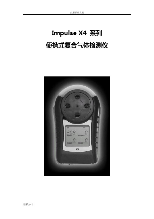
Impulse X4 系列便携式复合气体检测仪操作说明书!重要提示:!在首次使用仪器以前请认真阅读本手册,您将会掌握仪器正确的使用方法和了解仪器的功能,包括操作,维护,功能设置等容。
!为了使操作者更安全,请按照手册中的要求,定期对仪器进行标定。
!如果在使用过程中,遇到的故障或问题在本手册中没有提到,请直接联系制造商Zellweger Analytics,或联系当地的代理商/服务商。
!警告和注意:·更换任何元器件都有可能损坏仪器的本质安全结构。
·如果需要使用存储卡,请选用Zellweger Analytics 提供的存储卡(订货号2566-0435),使用其它的存储卡有可能损坏仪器的本质安全结构。
·在允许的储存期之后激活检测器,有可能影响仪器的使用性能和保质期。
·应使用许可的5号干电池,如劲量电池,不要使用质量低下的干电池,以免影响仪器的本质安全性能。
·在更换电池时,应同时更换2节型号相同的新电池。
·在电池欠压提示后,应尽快更换新电池,以免旧电池漏液损坏仪器。
·在低温环境下,电池的寿命会缩短。
·更换电池时,应该在安全环境下进行。
·当更换任何一个传感器的情况下,都需要对仪器进行标定。
·在每天使用以前,应完成仪器的自检过程。
·定期的对仪器用标气进行测试,检查声、光、振动报警是否正常。
·标定时应选用厂家或国家认证合格企业提供的标准气体。
·标定时应在良好通风的环境下进行,以避免污染。
·不要在仪器电量不足的情况下标定。
·不要在富氧的环境下使用本仪器。
·可燃气体传感器的灵敏度会受到高浓度硫化物,卤素化合物,含硅化合物,以及含铅气体或蒸汽的影响,也叫“中毒”,应避免在以上的环境中使用仪器,如果必须使用,则使用完后应对仪器进行检测和标定,以免影响以后的使用。
- 1、下载文档前请自行甄别文档内容的完整性,平台不提供额外的编辑、内容补充、找答案等附加服务。
- 2、"仅部分预览"的文档,不可在线预览部分如存在完整性等问题,可反馈申请退款(可完整预览的文档不适用该条件!)。
- 3、如文档侵犯您的权益,请联系客服反馈,我们会尽快为您处理(人工客服工作时间:9:00-18:30)。
HoneywellAnalytics©2004 Honeywell Analytics Issue 1 12/2004 MIDAS-A-001目录1 目录 22 概述 53 产品概述 5 3.1 主机架 6 3.1.1 显示器模块 63.1.2 泵模块 7 3.1.3 传感器暗盒腔 73.2 安装托架底座 73.2.1 安装托架 73.2.2 终端模块 73.3 传感器盒 83.3.1 偏致传感器盒 83.4 机壳 84 默认配置 95 安装95.1 探测器的安装和定位 105.2 机械安装 115.3 样品和排气管道计算 125.4 在线过滤器 135.5 本地化探测器选购件 145.6 电气安装 155.7 电连接 17 5.8 改装主机架 185.9 安装传感器盒 196 探测器启动程序 197 总体操作 21 7.1 正常操作模式 217.1.1 重置报警、故障和维护故障 227.2 浏览模式 227.2.1 浏览模式菜单概述 237.3 设置、校准和测试模式概述 247.3.1 设置菜单概述 247.3.2 校准菜单概述‘CAL’ 267.3.3 测试菜单概述‘ tESt’ 278浏览、设置、校准和测试模式子菜单的导向的详细程序 288.1 浏览模式 288.1.1 复查软件‘SW’ 288.1.2 复查报警‘ ALm’ 298.1.3 复查故障‘ FLt’ 298.1.4 复查校准 ‘ CAL’ 298.1.5 复查日期和时间‘timE’ 298.1.6 复查探测器地址‘ nEt’ 308.1.7 复查事件标识‘ Hi St’ 308.2 设置、校准和测试模式 308.2.1 设置菜单‘ SEt’ 318.2.2 设置报警‘ ALm’ 318.2.3 设置故障‘ FLt’ 348.2.4 设置校准间距 ‘ CAL’ 348.2.5 设置日期和时间 ‘timE’ 558.2.6 设置地址‘ nEt’ 358.2.7 设置密码 ‘ PWd’ 368.3 校准菜单‘CAL’ 368.3.1 零点校准 ‘ 0CAL’ 368.3.2 间距校准‘ SPAn’ 378.3.3 流量校准‘ FLoW’ 388.3.4 mA 校准 ‘mA 4-20’ 388.4 测试菜单‘ tESt’ 398.4.1 颠簸测试 ‘ bUmP’ 398.4.2 报警/故障测试‘ Si m’ 398.4.3 禁止状态‘ I nH’ 409 常规维护 41 9.1 传感器盒的更换 419.1.1 传感器盒的安装/更换 419.2 泵的更换 43 9.3 重新组装探测器 469.4 过滤器的更换 4610 热解器模块选项 4710.1 安装热解器模块 4810.2 重新组装MIDAS® 探测器 4911 模拟输出模块 51 11.1 安装模拟模块 5111.2 重新组装MIDAS® 探测器 5212 找出故障并诊断 5313 REFLEX®ٛ5414 内置的网络服务器 5414.1 物理的网络组件 5414.2 网络设置 5414.3 运行网络浏览器 5415 典型安装拓扑 5615.1 常规安装 57 15.2 Modbus/TCP 安装 5715.3 通过以太网供电(POE) 的安装 5716 订购信息 58 16.1 MIDAS® 发送器 5816.2 MIDAS®热解器 5816.2 MIDAS® 热解器 5816.3 MIDAS® 模拟输出模块5816.4 MIDAS®插入式传感器盒(标准保修期) 5916.5 MIDAS®插入式传感器盒(延长保修期)6016.6 完整的MIDAS®气体探测器套件 6116.7 附件及备件 6117 一般规格 6218 校准及颠簸测试 6319 保证声明6720 软件菜单叙述图表 6920.1 高级6920.2 浏览模式7020.3 复查软件的信息、报警、故障及气体校准7120.4 复查日期/时间和网络7220.5 复查事件日志7320.6 设置模式7420.7 设置报警、故障及气体校准 7520.8 设置日期/时间和网络7620.9 设置密码7720.10 校准模式7820.11 校准气体零点及间距7920.12 校准——流量校准 8020.13 校准——4-20 mA 8120.14 测试模式8220.15 测试颠簸、报警/故障模拟 8320.16 测试禁止8421 联系详情 852 概述作为一个提取式气体取样系统,MIDAS气体探测器能在本地或从一个远程点提取一个样品到位于探测器机架内的传感器盒。
可以提供较广范围的毒气、可燃气体和氧气传感器盒,以便实现半导体和其他生产工业中使用或产生的气体探测。
MIDAS是用于墙面安装的,能够通过自身背光LCD 和LED显示气体浓度、报警、故障信息。
位于显示屏下方的简便易用的4按钮键盘为设置,浏览,操作和更改探测器配置提供了便利。
MIDAS标配有内置的灵活电源和通讯能力。
其中包括3个插件继电器、0-22 mA 模拟输出装置、Modbus/TCP、信号和服务连接输出装置以及革新的以太网供电(PoE)协议,该协议实现了所有电源、控制和通讯要求的单一以太网连接。
3 产品概述MIDAS®气体探测器由四部分构成:主机架、安装托架底座、传感器盒和机壳。
图1显示了MIDAS®的总配置图。
另外,还有一个用于NF3探测的可选热解器模块和用于连接外部4-20 mA 装置的可选模拟模块。
关于这些选购件请分别参考第10节和第11节。
图1. MIDAS®总配置分解图机壳主机架安装托架底座传感器盒主机架包括显示器模块、泵总成、插入式传感器暗盒腔。
图2. 主机架泵模块 显示器模块传感器暗盒腔3.1.1 显示器模块显示器模块位于主机架的前方,包括一个大型字母数字和图形背光LCD 、3个LED 指示器和一个4按钮键盘。
正常操作下,LCD 和LED 会显示气体浓度、报警和系统状态。
在设置、浏览、校准和测试模式中,LCD 会显示相关的菜单选项。
这些菜单借助于“▲”上、“▼”下、“✓”接受、“X ”取消按钮对操作进行了简单的导向。
图3. MIDAS ٛ 显示器模块平面示意图1. 红色报警 LED2. 正常操作图标3. 浏览模式图标4. 绿色电源LED5. 设置模式图标6. 校准模式图标7. 黄色故障LED8. 测试模式图标9. 气体浓度和信息显示区域 10. 显示的部件 11. 密码图标 12. 接受按钮 13. 地址图标 14. 网络图标 15. 禁止图标 16. 故障图标 17. 向上按钮18. 报警级别1图标▲报警级别2 图标(用于可燃气体和有毒气体) 缺氧报警图标▼氧气过量报警图标 ▲ 19. 取消按钮20. 零点 和间距 校准图标 21. 流量指示器泵模块位于主机架的背面。
它通过(连接到位于主机架的前面的传感器暗盒腔)在线过滤器从进气口(位于安装托架总成底部)吸入气体样品。
然后气体样品通过位于安装托架总成底部的排气口被排出。
泵和过滤器总成的设计应本着便于替换的原则。
关于替换的详细内容,请分别参考9.2 和 9.4部分。
3.1.3 传感器暗盒腔传感器暗盒腔位于显示屏模块下方的主机架前方的位置。
插入式传感器盒就安装于该区域,实现了传感器盒和其他电子部件的电连接,同时供给暗盒腔(传感器盒暴露的区域)样品气体。
传感器盒安装的详细内容,请参考第5.9部分。
3.2安装托架总成安装托架总成包括探测器安装托架、终端模块、气体样品进气口和出气口、电缆/电线引入装置和以太网通讯插座。
图4. 安装托架底座安装托架终端模块进气口电缆引入装置出气口以太网/PoE(以太网供电)插座3.2.1 安装托架金属安装托架具有两个沟槽,可以使用两个合适的定位螺丝轻易地将探测器安装到墙面上。
关于探测器安装的详细信息,请参考第5部分。
3.2.2终端模块终端模块位于安装托架上。
所有到MIDAS®的电连接都是通过该模块实现的。
到终端模块区域的线接入是通过位于安装托架总成底部的PG16电缆/电线引入装置完成的。
3.3 传感器盒可以将各式各样的毒气、可燃气体或氧气传感器盒安装到MIDAS®上。
插入式传感器盒位于主机架前方的传感器暗盒腔内。
要进入该腔内,可通过旋开位于探测器前方的翼形螺钉移除机壳即可。
如同无需任何工具就可以轻易插入探测器内一样,可以轻易地安装或替换预校准只能传感器盒。
图5. 传感器盒锁定牌连接器正面背面3.3.1偏致传感器盒某些传感器盒出厂时配有一个电池动力电源,旨在保持电池有效地“预热”并在安装入MIDAS®仪器中时随时进行监测。
偏压电池供应用于TEOS、NO 和 O3。
偏置电路在插入MIDAS®系统前被移除,因而传感器盒可随时用于有效的气体探测。
如果未使用偏电压(例如,电源故障期间),那么在开始有效的气体探测前,电池将需要较长的时间恢复。
外加电源损失的时间越长,恢复时间就越长。
关于每个传感器盒的信息,请参考相关的传感器盒数据表。
为了避免由于不可预见电源损失带来的气体探测损失风险,我们建议使用电源管理解决方案,例如:不间断电源、电池备援,等等。
备注:如果传感器盒由未授权人员打开,那么传感器报修单将无效。
3.4机壳机壳能提供环境保护功能并安装于主机架的顶端、前部和侧面。
前面板具有用于LCD、LED 和传感器盒(安装在传感器暗盒腔内)的浏览窗口。
LCD窗口下是4个按钮,可用于操作探测器软件菜单。
可以很容易地移除机壳从而进入机架,只需旋开前面板上的翼形螺钉并向前推机壳,直至脱离主机架即可。
图 6. MIDAS®机壳LED 窗口LCD窗口按钮传感器盒浏览窗口翼形螺钉4 默认配置作为标准件,MIDAS®气体探测器是工厂预先配置的,具体如下:表1. MIDAS®默认配置电源:0 mA1.0 mA3.0 mA20.0 mA2.0 mA21.0 mA故障(开路)故障维护故障4.0到气体读数(正常操作)禁止(测试模式)超出额定范围毒气可燃气体氧气满标 (FS)典型地 4 x 毒气阈限 (TLV)100%爆炸下限(LEL) 125% 体积 (v/v)最低报警级别 (LAL)典型地1/2 TLV 10% LEL 5% v/v较低可探测值(LDL)典型地0.4 TLV 9% LEL 0% v/vLDL是区别于零的最小可探测级别报警级别 1 of 1/2 TLV10% LEL23.5% v/v (上升)报警继电器1常闭,报警上电。
常开触点(NO),关闭报警。