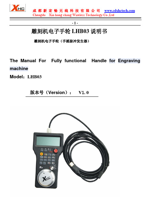
面板式电子手轮使用说明书
LHB03有线电子手轮说明书
Button
implementation machine
X 分中按钮
将 X 工件坐标分中
X Coordinates 1 / 2 X Coordinates 1 / 2 Button
Y 分中按钮
将 Y 工件坐标分中
Y Coordinates 1 / 2 Y Coordinates 1 / 2 Button
成 都 新 宏 畅 无 线 科 技 有 限 公 司 Chengdu Xin hong chang Wireless Technology Co.,Ltd
-3-
鼠标双击图标,开始安装驱动 Double click the icon to begin installing the driver
breakpoint
浮 动 对 刀 开 始 / 停 止 当按下该键,机床执行对刀操作:同时,YES 和 NO 提示
按钮/复位按钮
灯闪烁,需要用户再次确认是否需要进行对刀。如果按下
YES 键,则开始对刀,LCD 的对刀图标闪烁;表示正在进 Floating on the knife
行对刀操作。按下 NO,则退出对刀。 start or stop or reset
Button
当机床处于加工运行状态下,按下该按钮,机床复位,停止
加工
When you press the button, the machine Operating the knife
YES and NO LED flashing lights, requires the user to reconfirm the need for the knife;
按照安装提示,直到驱动安装完成 Please follow the computer prompts, Set up the Driver Software Until flished Set up 第 2 步:(Step 2) 打开软件:打开刚刚安装的驱动软件,然后再打开数控系统软件 NcStudio OPEN The Driver Software,then Open The NcStudio Software
气动执行器手轮机构操作说明

气动执行器手轮机构操作说明
手轮机构与气动执行器配套使用,当气源信号出现故障,阀门无法开启、关闭,或固定在某一位置时,就必须通过手轮来完成。
1.阀门的开启方向,通常是逆时针表示打开,顺时针表
示阀门关闭。
因此,开关阀门时要注意方向。
2.阀门上的手轮、手柄是按正常人力设计的,因此,在
阀门使用上规定,不允许操作者借助杠杆和长扳手开启或关闭阀门。
3.当手轮全开后,应倒转少许,使螺纹之间严紧,以免
松动损伤。
4.若手轮是做限位用的,应在预定位置,检修时可借助
标尺和记号记住它们全开和全关位置,这样可以避免全开时顶撞死点。
5.阀门出厂时,不论气动执行器是正作用还是反作用,
手轮都在开启状态,并都用锁母锁死,以免操作人员误操作把手轮关下去,阀门无法打开或达不到所需流量,造成不必要的事故和损失。
6.操作人员在用手轮操作前,先将手轮锁母松掉,再进
行操作,操作完成后,如无特殊说明,一定要把手轮打开,并用锁母锁死。
西安秦申特种调节阀有限责任公司
2009年10月10日。
fagor 100P_100E手轮手册

100P / 100EInstrucciones de Montaje Installation Manual Instructions de Montage Manuale d'Installazione Anbau-AnleitungCode: 14400019 Manual version. 0510< 100P / 100E v0510 - 2 >ModelosPortátil 100 PCon pulsador de selección de ejes, cable protegido de 3 m y conector (7 pin).Empotrable 100 ESin pulsador de selección, cable de 1 m, sin conector y frontis plano de fijación.ModelsPortablel 100 PWith axis selector button, shielded cable (10ft, 3m) and a 7-pin connector.Built-in 100 EWith 1 m (3 ft) cable, flat mounting faceplate and without axis selector button or connector.TypenHandrad 100 PAuswahl der Achsen über Schaltknopf möglich, Abgeschirmtes 3 m-Kabel mit Anschlußstecker (7 pin).Handrad - Einbaumodell 100 EAuswahl der Achsen nicht möglich, 1m-Kabel ohne Anschlußstecker, flacheFrontplatte mit Bohrungen zur Befestigung .ModèlesPortable 100 PAvec touche de sélection d'axes, câble blindé de 3 m de longueur et connecteur (7 pin).Encastrable 100 ESans touche de sélection d'axes, câble d'un mètre et face plate de fixation.ModelliPortatile 100 PCon pulsante selezione assi, cavo protetto da 3 metri e connettore (7 pin).Ad incasso 100 ECon cavo da 1 metro, motaggio piattaforma piana, senza pulsante di selezione assi e connettore.DIMENSIONES / DIMENSIONS / DIMENSIONI / ABMESSUNGENCaracterísticas mecánicasVelocidad de giro: 10 rev/seg.Par: ~ 10 N. cm Peso: 1 KgEstanqueidad: IP-53 (DIN 40050)Datos ambientales:· Temperatura funcionamiento: 0 ºC ... 60 ºC· Temperatura almacenamiento: -30 ºC... 80 ºC · Humedad relativa: 95% sin condensar.Mechanical specificationsTurning speed: 10 RPS.Torque: ~ 10 N. cm Weight: 1 KgSealing protection: IP-53 (DIN 40050)Environmental data:· Operating temperature: 0 ºC ... 60 ºC· Storage temperature: -30 ºC... 80 ºC · Relative humidity:95% without condensation.Caractérístiques mécaniquesVitesse de rotation: 10 T/sec.Couple: ~ 10 N. cm Poids: 1 KgEtancheité: IP-53 (DIN 40050)Données d'ambiance:· Température de fonctionnement: 0 ºC ... 60 ºC· Température de stockage: -30 ºC... 80 ºC · Humidité relative:95% sans condensation.Caratteristiche meccanicheVelocità di rotazione: 10 giri / secondo Momento torcente: ~ 10 N. cm Peso: 1 KgProtezione: IP-53 (DIN 40050)Dati ambientali:· Temperatura funzionamento: 0 ºC ... 60 ºC· Massimo intervallo di temperatura: -30 ºC... 80 ºC · Umidità relativa:95% senza condensa.Mechanische DatenDrehzahl: 10 Usec.Drehmoment: ~ 10 N. cm Gewicht: 1 KgSchutzart: IP-53 (DIN 40050)Umgebungsbedingungen:· Betriebstemperatur: 0 ºC ... 60 ºC · Lagertemperatur: -30 ºC... 80 ºC · Luftfeuchtigkeit:95% ohne Kondensation.Taladros Panel 100P Panel drilling 100P100 P100 E< 100P / 100E v0510 - 3 >Carácteristicas eléctricasFuente de luz: IRED (diodo emisor infrarrojos).Tensión de alimentación: Vcc Entre 5 y 24 Vdc ± 10%.Consumo; 30 mA máx (sin carga).Señales de salida.Dos trenes de impulsos A y B desfasados 90º más una señal SELECT (en los modelos 100P). La señal B retrasada con respecto a A, al girar el volante en sentido horario.Impulsos / vuelta: 25Electrical specificationsLight source: IRED (infrared emitting diode).Supply voltage: VdcBetween 5 and 24 Vdc ± 10%.Consumption; 30 mA max (without load).Output signalsTwo trains of pulses A and B shifted 90ºplus one axis select signal (model 100P).Signal A ahead of signal B when turning the handwheel clockwise.Lines / turn: 25Caractéristiques électriquesSource lumineuse: Diode à infrarouge.Tension d'alimentation: Vcc Comprise entre 5 et 24 Vcc ± 10%.Consommation; max. 30 mA (à vide).Signaux de sortie.Deux trains d'impulsions A et B déphasés de 90º, plus un signal select (pour le modèle 100P). Le signal A précède le signal B en tournant dans le sens horaire.Impulsions / tour: 25Caratteristiche elettrichesorgente di luce: IRED (diodo emettitore all'infrarosso).Tensione di alimentazione: Vcc Fra 5 e 24 Vdc ± 10%.Consumo; 30 mA máx (senza carico).Segnali di Uscita.Due treni di impulsi A e B sfasati di 90º piùun segnale di selezione (modello 100P).Segnale A in anticipo rispetto a B ruotando la manopola in senso orario..Impulsi / giro: 25Elektrische DatenLichtquelle: Infrarot-Diode.Versorgungsspannung: Vdc 5-24 Vdc ± 10%.Stromverbrauch; 30 mA max (ohne Last).Ausgangssignale.Impuls A und B, 90º Grad phasenversetzt,ferner ein Impuls für die ACHSAUSWAHL (bei Handrad Typ 100P). Signal B folgt dem Signal A bei Drehen des Handrads im Uhrzeigersinn (mit Blick auf die Welle).Impulse / umdrehung mit.: 25Longitud de cable permitida: 20 m Maximum cable length: 20 m (65 ft)Longueur max. du câble: 20 mLunghezza massima del cavo: 20 m Max. zulässige Kabellänge: 20 mCircuito de salida: Colector abierto con resistencia pull-up interna ( 5.6 KOhm).Output circuit: Open collector with built-in 5.6 KOhm pull-up resistor.Circuit de sortie: Collecteur ouvert avec résisance "pull-up" interne.Circuito uscita: Collettore aperto con resisteza "pull-up" interna (5.6 KOhm).Ausgangs-Stufe: Offener Kollektor (open collector) mit eingenbautem 5.6 KOhm "Pull-up" Widerstand.Pulsador sin actuar Switch ffTouche pas poussée SpentoSchaltknopf nicht betätigtSELECTα = 90º ± 35ºß = 45º ± 22ºT1/T2 = 1 ± 0.1VOH > Vcc - 2.6 V. a Isource < 0.4 mA VOL < 05 V. a Isink < 4 mAPulsador actuado Switch onTouche poussée AccesoSchaltknopf betätigtGARANTÍAPlazo: 12 meses a partir de la fecha de expedición de fábrica.Cubre gastos de materiales y mano de obra de reparación en FAGOR. Los gastos de desplazamiento son a cargo del cliente.No cubre averías por causas ajenas a FAGOR como: golpes, manipulación por personal no autorizado, etc.WARRANTYThe equipment is under warranty for 12 months from factory delivery date.This warranty covers both material and labor repair costs at FAGOR. In case of repair at customer's facilities, any travel expenses are payable by the customer.This warranty does not cover damages and faults arised from causes not related to normal operation of the equipment, such as blows, poor assembling or handling by unauthorized personnel, etc.GARANTIETerme: 12 mos à partir de la date d'expédition de l'usine.Les frais de main d'oeuvre et matériels sont couverts par la garantie. Les frais de déplacements et de séjour sont à la charge du client.La garantie ne couvre pas les fautes occasionnées par des causes étrangères au fonctionnement normal comme: chocs, chutges, manipulation par du personnel non autorisé, etc.GARANZIADurata: 12 mesi a partire dalla data di spedizione dallo stabilimento.Comprende le spese dei materiali di rIparazione e della manodopera press la FAGOR. Le spese di trasferta sono a carico del cliente.Non comprende guasti prodotti da cause non imputabliti all FAGOR come, colpi, manipolazioni di personale non autorizzato, ecc.GEWÄHRLEISTUNGDie Gewährleistungfrist beträgt 12 Monate ab Versanddatum des Werks.Die Gewährleistung deckt den Material- und Arbeitsaufwand für eine Reparatur bei FAGOR. Reise und Aufenthaltskosten bei einer Reparatur im Werk des Kunden müssen berechnet werden.Die Gewährleistung deckt nicht Beschädigungen und Funktionsmängel, welche durch abnormale Nutzung entstehen können: Schläge, Bedienungs- und Montagefehler bei ungeschultem Personal, Überschwemmung mit kühl-Schmiermittel, usw.。
海德汉TNC 620 HSCI Gen 3驱动器紧凑型数控系统说明书

TNC 620 HSCIGen 3驱动器镗铣类机床的紧凑型数控系统面向机床制造商07/2021TNC数控系统带驱动系统一般信息TNC 620•铣、钻和镗机床的紧凑型数控系统•轴数:8个控制环,其中2个可配置为主轴•用海德汉变频器系统并优选使用海德汉电机•全数字化HSCI接口和EnDat接口•尺寸紧凑•CF闪存卡•海德汉Klartext对话式和G代码(ISO)编程•标准铣、钻和镗加工循环•测头探测循环•程序段处理速度快(1.5 ms)19英寸显示屏(纵向)版•一体化的显示屏、键盘和主机(MC8410)•显示器下端为键盘•多点触摸式操作15英寸显示屏(横向)版•一体化的显示屏和主机(MC8420)•独立的键盘单元•多点触控操作系统测试海德汉数控系统、功率模块、电机和编码器通常是完整系统的组成部件。
因此,需要综合测试整个系统,而不能仅仅测试各单独设备的技术性能。
损耗件海德汉数控系统中含易损件,例如、后备电池和风扇。
标准本产品遵循的标准(ISO,EN等),请见样本中的标注。
注意Intel、Intel Xeon、Core和Celeron是Intel Corporation的注册商标。
有效性本文所述功能和技术参数适用于以下数控系统和NC数控软件版本:TNC 620,NC数控软件版本817600-08(需出口许可证)817601-08(无需出口许可证)本样本是以前样本的替代版,所有以前版本均不再有效。
如有变更,恕不另行通知。
要求有些技术参数对机床的配置有特别要求。
请注意,有些功能还需机床制造商开发专用PLC程序。
功能安全特性(FS)如果未明确区分标准部件与FS部件(FS = 功能安全特性),所介绍的信息适用于这两类部件(例如, TE 735,TE 735 FS)。
对于带功能安全特性的部件,在其产品标识的最后带标识符“(FS)”,例如,UEC 3xx (FS)2目录TNC数控系统带驱动系统2一览表4HSCI控制部件16附件23电缆概要37技术说明44数据传输和通信73安装信息77主要尺寸79一般信息101其它海德汉数控系统103主题索引104请注意技术参数表内的页码。
手控运动功能使用简易说明
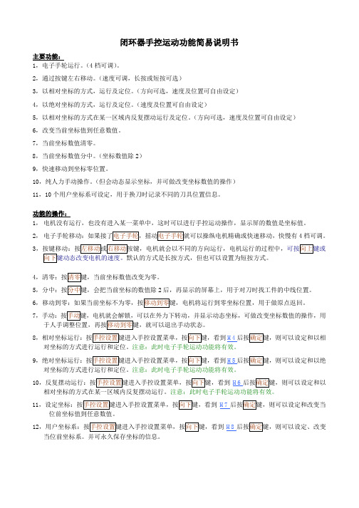
闭环器手控运动功能简易说明书主要功能:1,电子手轮运行。
(4档可调)。
2,通过按键左右移动。
(速度可调,长按或短按可选)3,以相对坐标的方式,运行及定位。
(方向可选,速度及位置可自由设定)4,以绝对坐标的方式,运行及定位。
(速度及位置可自由设定)5,以相对坐标的方式在某一区域内反复摆动运行及定位。
(方向可选,速度及位置可自由设定)6,改变当前坐标值到任意数值。
7,当前坐标数值清零。
8,当前坐标数值分中。
(坐标数值除2)9,快速移动到坐标零位置。
10,纯人力手动操作。
(但会动态显示坐标,并可做改变坐标数值的操作)11,10个用户坐标系可设定,用于换刀时记录不同的刀具位置信息。
功能的操作:1,电机没有运行,也没有进入某一菜单中,这时可以进行手控运动操作,显示屏的数值是坐标值。
2,电子手轮移动:如果接了电子手轮,摇动电子手轮就可以操纵电机精确或快速移动,快慢有4档可调。
3,按键移动:按左移动或右移动按键,电机就会以不同的方向运行,电机运行的过程中,可按向上键或向下键动态改变电机的速度。
默认的方式是长按方式,但也可以设置为短按方式。
4,清零:按清零键,当前坐标数值改变为零。
5,分中:按分中键,会把当前坐标的数值除2后,再显示的屏幕上,用于对刀时找工件的中线位置。
6,移动到零:如果当前坐标不为零,按移动到零键,电机将运行到零坐标位置,用于做原点返回。
7,手动:按手动键,电机就会解锁,可以在外力下转动,并显示动态坐标,可做改变坐标数值的操作,用于人手调整位置,再按移动到零键,就可以退出手动状态。
8,相对坐标运行:按手控设置键进入手控设置菜单,按向下键,看到H4后按确定键,则可以设定和以相对坐标的方式进行运行和定位。
注意:此时电子手轮运动功能将有效。
9,绝对坐标运行:按手控设置键进入手控设置菜单,按向下键,看到H5后按确定键,则可以设定和以绝对坐标的方式进行运行和定位。
注意:此时电子手轮运动功能将有效。
10,反复摆动运行:按手控设置键进入手控设置菜单,按向下键,看到H6后按确定键,则可以设定和以相对坐标的方式在某一区域内反复摆动运行。
ZWGP系列无线电子手轮说明书

ZWGP系列无线电子手轮说明书使用本产品之前,请阅读本手册并妥善保存手册作日后参考适用于德国西门子(SIEMENS )、日本三菱(MITSUBISHI )、法那科(FANUC )、西班牙发格(FAGOR )、法国NUM 、台湾宝元、台湾新代等数控。
1、采用无线通讯频段,无线433MHZ 距离40米;2、采用自动跳频功能,同时使用32套无线手轮,互不影响;5、轴选和倍率信号支持二进制编码和格雷码等信号类型;4、支持6档轴选功能,3档倍率选择功能;6、支持5V 差分脉冲信号,非差分脉冲信号,24V 脉冲信号等多种脉冲信号类型;3、支持急停按钮功能,和3个扩展按钮开关量输出;7、低功耗设计,2节AA 电池可以使用1个月以上;注释:1、状态指示灯:电源灯(左一):OFF 档打开后,电源灯常亮; 信号灯(左二):操作手轮时,信号灯常亮;低电压报警灯(右一):电池电量过低时,报警灯闪烁或者常亮;2、使能按钮:按住使能按钮后,激活轴选和倍率信号,并且脉冲编码器输出有效;3、自定义按钮:无任何功能的按钮,控制接收器上对应的一个开关量输出;型号:ZTWGP-3:ZTWGP 接收器注释:1、状态指示灯:电源灯(左一):OFF 档打开后,电源灯常亮; 信号灯(左二):操作手轮时,信号灯常亮;低电压报警灯(右一):电池电量过低时,报警灯闪烁或者常亮;2、使能按键:按住使能按钮后,激活轴选和倍率信号,并且脉冲编码器输出有效;型号:ZTWGP:ZTWGP 接收器接收器功能介绍COM1:轴选倍率信号输出的公共端;可以接0-24V 公共信号COM2:3个自定义按钮输出的公共端;型号:ZTWGP 接收器:接收器端子定义产品功能描述注释:1、状态指示灯:电源灯(左一):OFF 档打开后,电源灯常亮; 信号灯(左二):操作手轮时,信号灯常亮;低电压报警灯(右一):电池电量过低时,报警灯闪烁或者常亮;2、正负快速移动按钮:按住“+”按钮,手轮连续发送正向脉冲; 按住“-”按钮,手轮连续发送负向脉冲;型号:ZWGP:ZWGP 接收器线号+5V 0V ABA-B-XYZ451X 10X 100X COM 红黑黄白透明白蓝黑棕黑红透明+黑蓝橙色绿黑白黑绿黑黄功能电源正极脉冲A相脉冲B相轴选X轴轴选Y轴轴选Z轴轴选4轴轴选5轴倍率1X档倍率10X档倍率100X档轴选倍率的公共信号颜色电源负极脉冲A-相脉冲B-相接收器功能介绍与端子定义无线电子手轮WGP型号规则059:产品外观:Z表示Z系列外观;9:TWGP:带急停按钮;WGP:则不带急停按钮:脉冲输出参数:01:表示5V,25毫安;A,B脉冲信号输出:100PPR03:表示5V,差分信号;A,A-;B,B-;脉冲信号输出:100PPR02:表示12V,5毫安;A,B脉冲信号输出:25PPR(适合三菱系统)04:开路输出;A,B脉冲信号.低电平,NPN输出.(适合PLC等)05:源极输出;A,B脉冲信号,高电平输出,PNP输出.(适合PLC):手轮支持的轴数量;5表示支持5轴;6表示支持6轴;:手轮轴选输出方式:A表示点对点输出;B表示编码输出:手轮倍率输出方式:A表示点对点输出;B表示编码输出:手轮支持的扩展按钮数量:3表示支持3个扩展按钮输出;:表示倍率特殊输出模式:X表示倍率信号为脉冲式输出(西门子系统专用):表示无线信号接收器的工作电压:05表示5V供电;12表示12V供电;24表示24V供电倍率编码输出1X和COM连通倍率10X: 10X和COM连通倍率100X: 倍率1X,10X都和COM连通倍率1X:型号:Z TWGP01-6 B A- 3 X脉冲输出选型指南型号参数描述适合系统电源DC5V,输出脉冲100PPR,相位输出为A,B两路脉冲序列A和B相差90;开路集电极电路,内装200欧5V上拉电阻日本法那科FANUC系统台湾中达电通TNC台湾忆图(HUST)系列国内如航天数控,华中数控,广州诺信凯恩帝KND等系列电源DC12V,输出脉冲25PPR,相位输出为A,B,两路脉冲序列A和B相差90开路集电极电路,内装2K欧12V的上拉电阻日本三菱MELDAS电子手轮(MELDAS M64;M65;E60等系统为电源DC12V,输出为DC5V)Gp01Gp02Gp03电源DC5V,输出脉冲100PPR,相位输出为A,A-,B,B-,采用5V差分脉冲信号输出适合台湾宝元,台湾新代SYNTEC系统,德国PA系统,典型如:海徳盟Higerman,海那克Higerman,广州数控GSK,开通数控 等数控系统;国外系统:西门子,NUM,西班牙法格FAGOR(NEW,8055I)等输出脉冲100PPR,相位输出为A,B两路脉冲序列A和B相差90;低电平,NPN输出日本法那科FANUC系统德国西门子等系列;适合PLC;Gp04输出脉冲100PPR,相位输出为A,B两路脉冲序列A和B相差90;高电平,PNP输出日本法那科FANUC系统德国西门子等系列;适合PLC;Gp05成都芯合成科技有限公司Chengdu XinHeCheng Technology Co .,Ltd网站:http ://www .wixhc .com客服电话:028-******** 如有印刷或翻译错误,望用户谅解。
Emotron HCP 2.0 手持式控制面板 使用说明书

Emotron HCP 2.0 Handheld control panel for Emotron FDU/VFX 2.0Emotron CDU/CDX 2.0Instruction manualEnglishHandheld control panel for Emotron FDU/VFX 2.0 and Emotron CDU/CDX 2.0The handheld control panel - HCP is a complete control panel, easy to connect to the variable speed drive, for temporary use when e.g. commissioning, servicing and so on.The HCP has full functionality including memory. It is possible to set parameters, view signals, actual values, fault logger information and so on. It is also possible to use the memory to copy all data (such as parameter set data and motor data) from one VSD (Variable Speed Drive) to the HCP and then load this data to other VSDs. For further information see Instruction manual for Emotron FDU/VFX 2.0 or Emotron CDU/CDX 2.0.Following cable kits are available:A.HCP cable for FDU/VFX Standard drives. 2 x 9-pin D-sub connectors, length 3 meters.B.HCP cable for CDU/CDX Compact drives.9-pin D-sub and RJ12 connectors (for connection to internal control board), length 3.3 meters.C.HCP cables for both CDU/CDX and FDU/VFX drives. One cable with 9-pin D-sub and RJ12 connectors + one cable with 2 x D-sub connectors.Connect the HCP to Emotron FDU/VFX 2.0It is easy to connect the HCP instead of the control panel or the blank panel in following way.1.Remove the control panel or the blank panel on theVSD. Then the RS232 connector will be visible.Fig. 1When you remove the blank panel or control panel you will be able to connect the HCP .B.Connect the standard RS232 cable, to the female connector on the VSD and to the connector on the HCP .Fig. 2RS232 cable for connecting the HCP to Emotron FDU/VFX 2.0C.Now it is possible to use the HCP .Part number Description01-5039-00Handheld Control Panel complete for FDU/VFX2.0 or CDU/CDX 2.0NOTE: When ordering the HCP it is important to specify if you are going to connect the HCP to Emotron FDU/VFX 2.0 or Emotron CDU/CDX2.0 so the correct cable kit is delivered.NOTE: It is important that only one control panel isconnected at the same time. Always remove/disconnect the existing control panel before connecting the HCP.Connect the HCP to Emotron CDU/CDX 2.0Fig. 3Adapter and cable for connecting the HCP toEmotron CDU/CDX 2.0.1.Mount the adapter to the RS232 connector on the HCP.B.Switch off the mains power supply.C.On Emotron CDU/CDX 008 - 018, remove the frontcover in order to expose the control board.Fig. 4Remove the front cover on EmotronCDU/CDX 008 - 018D.On Emotron CDU/CDX 026 - 046, remove the sidecover in order to expose the control board .Fig. 5Remove the side cover on EmotronCDU/CDX 026 - 046E.Disconnect the RJ12 cable from the built in controlpanel and connect the RJ12 cable from the HCPFig. 6Connect the HCP cable to the RJ12 connector on the control board.WARNING!Always switch off the mains voltage if it isnecessary to open the VSD and wait at least5 minutes to allow the capacitors todischarge.Remove the front coverRemove the side coverConnect theHCPcable to theRJ12 connector.F.Now it is possible to switch on the mains power supplyand use the HCP.WARNING!Be careful as the cover is open. Although theconnections for the control signals and theswitches are isolated from the main voltage, do not touch the control board when the variable speed drive is switched on.After having used the HCP, turn off the main power supply. Wait at least 5 minutes to allow the capacitors to discharge.1.Disconnect the cable from the control board. Reconnectthe cable from the built in control panel again.B.Mount the cover.C GD r i v e s & A u t o m a t i o n , 01-5925-01r 1 2015-04-20CG Drives & Automation Sweden ABMörsaregatan 12Box 222 25SE-250 24 Helsingborg SwedenT +46 42 16 99 00F +46 42 16 99 49/。
按操作面板上的手轮X按键

• 任务实施
一、知识准备
1. 数控铣床介绍 数控铣床是用计算机数字化信号控制的铣床。 2. 数控铣床的组成 数控铣床一般由机床主机、控制部分、驱动部分、 刀库及自动换刀装置、辅助部分等组成。
• 任务实施
3.数控铣床面板按键与功能介绍 (1)FANUC系统面板介绍
(2)机床操作面板介绍
• 任务实施
• 任务实施
子任务五:试切法对刀
步骤:
3、数据存储 将测得的X、Y、Z值输入到机床 工件坐标系存储地址G54~G59代码 中任一一个,一般选G54存储对刀参 数。
• 任务评价
• 任务实施
子任务三:手动模式
步骤: 按操作面板上的“手动”按键,进入手动模 式。 按MDI单元上的“POS”按键,LCD进入坐标画 面。 分别按操作面板上的手动进给区域中的各个 按键,配合快速倍率按键“F0”、“25%”、 “50%”、“100%”的选择,仔细观察刀架的移动 方向与速度的变化,并观察 LCD中坐标的变化。
• 任务实施
子任务五:试切法对刀
步骤: 2、Z向对刀
(1)将刀具快速移至工件上方。 (2)起动主轴中速旋转,快速移动工作台和 主轴,让刀具快速移动到靠近工件上表面有一 定安全距离的位置,然后降低移动速度让刀具 端面接近工件上表面。 (3)靠近工件时改用微调操作(一般用0.01 来靠近),让刀具端面慢慢接近工件表面(注 意刀具特别是立铣刀最好在工件边缘下刀,刀 的端面接触工件表面的面积小于半圆,尽量不 要使立铣刀的中心孔在工件表面下刀),使刀 具端面恰好碰到工件上表面,再将Z轴再抬高 0.01,记下此时机床坐标系中的Z值,如140.400等,则工件坐标系原点在机床坐标系 中的Z坐标值为-140.400.
项目一
FR-PA07 面板操作说明书
Enclosure surface operation panelFR-PA07INSTRUCTION MANUALINVERTERThank you for purchasing the enclosure surface operation panel (FR-PA07). This instruction manual gives handling information and precautions for use of this equipment. Incorrect handling might cause an unexpected fault. Before using the equipment, please read this manual carefully to use the equipment to its optimum performance.Please forward this instruction manual to the end user.This product is an option dedicated for the FR-E700 series.Refer to the inverter unit's instruction manual for details on the operation panel functions, operation methods and handling methods.1.InstructionsFor the FR-E700 series inverters manufactured during or before the period shown by the following serial numbers, there are restrictions mentioned below.1)verification) does not function. Display turns into the reading indication, but reading is not executed. If writing or verification is executed, an error occurs.2)3)4)SERIAL number checkRefer to the inverter manual for the position of the rating plate.Rating plate example The SERIAL consists of 1 version symbol, 2 numeric characters or 1 numeric character and 1 alphabet letter indicating year and month, and 6 numeric characters indicating control number.Month is indicated as 1 to 9, X (October), Y (November), and Z (December).{{{{{{{{SymbolYear Month Control number SERIAL (Serial No.)TypeSERIAL number TypeSERIAL number FR-E720-0.1K to 0.75K J7{{{{{{{FR-E740-0.4K to 7.5K D7{{{{{{{FR-E720-1.5K to 5.5K K7{{{{{{{FR-E720-7.5K L7{{{{{{{FR-E720-11K, 15KG7{{{{{{{2.Connection2.1Installation using a connection cable (FR-CB20 )Securely insert one end of connection cable into the PU connector of the inverter and the other end into the connection connector of the FR-PU07 along the guides until the stoppers are fixed.2.2Removal when the connection cable (FR-CB20 ) is usedHold down the tab (stopper) at the cable end and gently pull the plug.NOTEy Install the FR-PA07 only when the front cover is installed.For details of the connection cable (FR-CB20 ), refer to the connection cable (FR-CB20 ) instruction manual.s and functions of the operation panel (FR-PA07)*Both PU and EXT are off on the inverters manufactured during or before the period shown by the serial numbers described on page 1.MODE SETSTOP RESET REV FWDPU EXT4.Operation*the serial numbers described on page 1.Refer to page 1)*DE SETP E DE SETP EDE SETP EDE SETP EDE SETP ETPU EXTTPU EXTHz AHz ARUN MON EXTPUHz ARUN MONMODE SMODE SMODE S TPU EXTDE SETP EPU operation mode (output frequency monitor)M o n i t o r /f r e q u e n c y s e t t i n gValue change Output currentmonitor P a r a m e t e r s e t t i n gParameter setting modeF a u l t s h i s t o r y(Example)and frequency flicker.Frequency setting has been written and completed!!Output voltagemonitorFaults history clearInitial value change listParameter write is completed!!Parameter and a setting value [Operation for displaying faults history] (Refer to the inverter manual)Past eight faults can be displayed.(The latest fault is ended by ".".)When no fault history exists, is displayed.4.2Operation lock (Press [MODE] for a while (2s))y Set "10 or 11" in Pr . 161y display appears.)yOperation using the setting dial and key of the FR-PA07 can be made invalid to prevent parameter change, and unexpected start or frequency setting.POINTSet "10 or 11" (key lock mode valid) inPr. 161 Frequency setting/key lock operation selection .Operation Display1.Screen at powering onThe monitor display appears.2.3.mode.appears.)4.(Pr. 161) appears.5.6.7.to set.8.Notey Release the operation lock to release the PU stop by key operation.4.3Use the setting dial like a potentiometer to perform operationPOINTSet "1" (setting dial potentiometer mode) in Pr. 161 Frequency setting/key lock operation selection .Changing exampleChanging the frequency from 0Hz to 60Hz during operationOperation Display1.Screen at powering onThe monitor display appears.2.3.Change the Pr. 161 setting to "1".(Refer to page 5 for change of the setting.)4.5.set frequency.If flickering "60.00" turns to "0.00", the Pr. 161 Frequency setting/key lock operation selection setting may not be "1".Independently of whether the inverter is running or at a stop, the frequency can be set byPr. 295 Magnitude of frequency change setting to change the5.Specifications5.1Standard specificationsItem SpecificationsAmbient temperature-10°C to +50°C (non-freezing)Ambient humidity90%RH or less (non-condensing)Storage temperature-20°C to +60°CAmbience Indoors (free from corrosive gas, flammable gas, oil mist, dust and dirt) Altitude, vibration Maximum 1000m above sea level for standard operation. 5.9m/s2or less Power supply Power is supplied from the inverter.Connection method Connection using the parameter unit connection cable (FR-CB20 ) 5.2Outline drawing and panel cutting drawing<Outline drawing><Panel cutting drawing>。
XD-40配置SIEMENS802D数控系统操作说明书
XD-40配置SIEMENS802D数控系统操作说明书XD-40数控铣床电⽓使⽤说明书(SINUMERIK 802D系统)中华⼈民共和国⼤连机床集团有限责任公司序⾸先感谢您使⽤本公司的产品,我们深信您所购买的产品具有坚实与⾼精度的品质,配合适当的维护,在未来的时间⾥,将带给您更优越的加⼯产品品质。
由于本公司持续不断地提⾼产品性能,同时您也可能有特殊要求,因此您可能会发现送达贵公司的机床与本⽂件有些差异,此仅表⽰新的改善⽅案已运⽤到您的机床上。
如有任何问题,请随时与本公司联系。
说明书中的所有附图与画⾯,均只是⽤于图解说明,有助于⽤户了解。
说明书中并不提供所有构件的实际尺⼨或公差值。
本公司有对本产品、机床规格及各种机床⽂件进⾏修改或完善的权利,没有告知先前使⽤者这些修正或改善的义务。
本机床所有随机⽂件在未得到本公司书⾯同意前,不得以任何形式或⽅法来重新制作、翻印或影印。
本公司保留上述有关权利。
⽬录1、电⽓安全2、机床电⽓概述3、机床操作概述4、机床编程概述5、机床电⽓维修概述6、部分参数的设定1.1 安全预防本机床安装有许多安全设置,以避免遭受伤害或破坏,操作者不能仅依赖于本机床的这些保护装置,⽽应该了解以下各章节说明后,⽅可进⾏操作和维修。
切不可随意操作、维修机床。
否则将⼤⼤增加个⼈伤害、机床损伤的可能性。
经过对本⼿册的阅读以及结合您对机床操作的常识及经验,将会降低⾮加⼯时间、提升⽣产效率及提⾼操作机床的安全性。
因在特殊运⽤的场合⽽附加的安全因素必须加以考虑,请参考相关的安全作业规章制度。
重要守则★未经培训的⼈员禁⽌维护或操作本机床;★禁⽌操作⼯尝试维修本机床;★请谨慎⼯作并随时注意安全。
如您⾝体已受药物或酒精的影响,请勿操作或维修本机床;★请勿使⽤压缩空⽓直接对着控制⾯板、电⽓箱喷吹;★必须知道“紧急停⽌按钮”所在位置;★如发⽣停电,应⽴即关闭总电源;★请勿改变参数、数量及其它设定值。
如有必要更改,请修正前先记录相关改动;★请勿让机床在⽆⼈看护下运转;★每⽇⼯作结束后,请将主电源关闭;1.2 电⽓安全装置及作⽤在特别留意上述章节之安全建议外,请了解以下安全装置及其作⽤,以保证机床的正常运转和⼈⾝安全。
AlphaPilot MFM系统手轮TR操作手册说明书

Handwheel TR Operation Manual ContentsPreface (3)Revision History (4)Glossary (5)Abbreviations (5)Definitions (5)Safety Information (6)Warranty (7)Introduction (8)Enabling FU control (9)Control allowed/not allowed (11)Control handover (13)Take control (13)Release/take control (13)Steering (13)Alarm handling (14)Dimming (15)Alarm speaker and lamp test (15)PrefaceThe Alphatron AlphaPilot MFM system is a type approved heading control system, designed to fit vessels of any size, including high speed crafts.The Handwheel TR is part of the AlphaPilot MFM system and is used for steering in manual FU steering mode.•Thoroughly read this operation manual before operating the equipment.•We recommend keeping this manual nearby the equipment to ensure ready access to it.GlossaryThe glossary contains a list of abbreviations and a list of definitions.AbbreviationsAbbreviations as used in this manual are explained in the table below.DefinitionsThe meaning of standard definitions as used in this manual are explained in the table below.Safety InformationThe signal words DANGER, WARNING and CAUTION used in this manual indicate the degree of hazard that may be encountered by the user. These words are defined as follows:DANGER Indicates a hazardous situation which, if not avoided, will result in deathor serious injury. This signal word is limited to the most extremesituations.WARNING Indicates a hazardous situation which, if not avoided, could result in deathor serious injury.CAUTION Indicates a hazardous situation which, if not avoided, could result in minoror moderate injury.The signal word NOTICE used in this manual indicates information considered important but not related to injury. It is typically used to prevent damage to equipment or property.To safely operate this system, the following DANGERS, WARNINGS, and CAUTIONS must be adhered to. Failure to comply with the precautions or with specific dangers, warnings, and cautions elsewhere in this manual violates safety standards of design, manufacture, and intended use of the equipment. ALPHATRON MARINE assumes no liability for the customer's failure to comply with these requirements.WARNING Do not disassemble or modify the equipment. Otherwise, it may cause a fire, or you may suffer an electrical shock.WARNING Immediately turn off the power and disconnect the power supply cable if the equipment is generating any smoke or odor, or is overheated. Immediately inform your local service agent of the symptom to have it repaired. Prolonged equipment operation under such a condition can cause a fire or electric shock.WARNING Do not place a container containing liquid on the equipment. Otherwise, it may cause a fire, or you may suffer an electrical shock if knocked over.WARNING When unplugging the instrument, be sure to remove the cord terminal correctly. If the cord is pulled, the cord may get damaged resulting in a fire or an electrical shock.WarrantyTo not to adversely affect the warranty, the following notices must be adhered to.NOTICE Operating personnel must not remove equipment covers. Only personnel trained and certified by ALPHATRON MARINE must make component replacement and internal adjustment.NOTICE Do not disassemble or modify the equipment. Failure to observe this instruction may cause equipment failure, and it will void the warranty.NOTICE Any modification to this equipment without prior written permission from ALPHATRON MARINE will void the warranty.NOTICE Installation of this product shall only be done by a certified installation company approved by either ALPHATRON MARINE or by an official ALPHATRON MARINE distributor. Acting otherwise will void the warranty.NOTICE This product contains no operator serviceable parts. Service and repair shall only be carried out by personnel trained and certified by ALPHATRON MARINE.NOTICE Do not place a container containing liquid on the equipment. The equipment can be damaged if knocked over.NOTICE When cleaning the surface, do not use any organic solvent such as thinner or benzine. Otherwise, the paint and markings on the surface may get damaged. For cleaning the surface, remove the dust and debris and wipe with a clean dry cloth.IntroductionThe Handwheel TR is part of the AlphaPilot MFM system and is used for steering in manual FU steering mode. The Handwheel TR is typically used in combination with an AlphaPilot MFM control unit.The Handwheel TR has 1 wheel and multiple buttons:-The alarm speaker buttons will illuminate when there is an alarm. The buttons are used to mute the speakers of the Handwheel TR and interconnected modules.-The buttons DIM - and DIM + are used to control the brightness level of the Handwheel TR and interconnected modules.-The buttons FU PS and FU SB are used to release/take FU control.-The handwheel is used to steer (step less control).Figure 1: Handwheel TREnabling FU controlPush the button FU PS or push the button FU SB to enable (both PS and SB) FU control*. The control mode indicator FU PS, and FU SB, and the handwheel indicator will illuminate, meaning that FU mode is enabled, and that the handwheel is enabled.NOTE: PS and SB rudder control is performed via 2 separate controllers, hence the presence of button FU PS and FU SB. These controllers are interlinked; It does not matter which FU button is pushed to enable FU control.*Note that control must be allowed, see subsection ‘Control handover’ on page 11. Note that another active controller may need to allow control handover first, see subsection ‘Control handover‘ on page 13.Figure 2: STBY mode enabledFigure 3: FU mode enabledControl allowed/not allowedWhen not in control, the Handwheel TR is in standby mode and handwheel is disabled (both control mode indicators STBY are illuminated and the handwheel indicator is not illuminated). Buttons FU PS and FU SB are illuminated when allowed to take control (see Figure 4 and Figure 5).NOTE: PS and SB rudder control is performed via 2 separate controllers, hence the presence of button FU PS and FU SB. These controllers are interlinked; Both buttons STBY are illuminated simultaneously and/or both FU buttons are illuminated simultaneously.FU control is steering in manual FU steering mode; therefore, the Mode Switch must be in position MAN position (Mode Switch 3 Pos) or AUTO|MAN (Mode Switch 2 Pos).FU control is not allowed when the Mode Switch is in position NFU (Mode Switch 2 Pos & Mode Switch 3 Pos) or AUTO (Mode Switch 3 Pos)).Figure 4: Enabling FU control not allowedFigure 5: Enabling FU control allowedWhen a non-illuminated button is pushed, the speaker produces 4 short successive beeps to indicate that the operation is not valid.Control handoverIf applicable, handover of control must be allowed first by the active controller to allow the Handwheel TR to take control (i.e. enable FU control).The method for control handover is preset during commissioning. Two system settings are possible, namely ‘Take control’ or ‘Release/take control’.Take controlAny controller can take control. Control handover allowance is not applicable.Procedure for Handwheel TR:-Push the button FU PS or FU SB to enable FU control. The control mode indicator FU and handwheel indicator will illuminate, meaning that the FU mode and the handwheel isenabled.Release/take controlAny controller can take control, only when the active controller allows control handover. Procedure for Handwheel TR:-Take controlAllow control handover from the active controller (refer to the respective operation manual for the procedure). The buttons FU PS and FU SB will illuminate to indicate that FU control is allowed. Push the button FU PS or FU SB to enable FU control. The control mode indicators FU PS and FU SB and handwheel indicator will illuminate, meaning that the FU mode and the handwheel is enabled.-Release controlTo allow control handover to another controller, push the button FU PS or FU SB, until thecontrol mode indicators FU PS and FU SB flash (this indicates that control handover isallowed).NOTE: The Handwheel TR stays in control until control is transferred to another controller.NOTE: The control mode indicators FU PS and FU SB keep flashing until control is transferred to another controller. There is no timeout. The speaker produces 3 short successive beepswith 10 seconds interval to indicate that the operation is not finished.NOTE: The Handwheel TR goes into standby mode when control is transferred to anothercontroller.SteeringIn FU control, the steering gear will move the rudder as per FU value command (rudder angle). Moving the handwheel to the neutral position will cause the rudder to move to the center position. Turning the handwheel farthest to the left will cause the rudder to move to a predefined maximum rudder angle, turning the handwheel farthest to the right will cause the rudder to move to the predefined maximum rudder angle in the opposite direction.Alarm handlingAn alarm speaker button is only illuminated when there is an internal alarm. When an alarm occurs, the alarm speaker button will flash in an uninterrupted sequence, and the speaker will beep in an uninterrupted sequence.NOTE: PS and SB rudder control is performed via 2 separate controllers, hence the presence of 2 alarm speaker buttons.The alarm speaker can be muted via the alarm speaker button.When the alarm is (read and) acknowledged on the AlphaPilot MFM control unit, then the illumination will be constant, and the speaker will be muted (if not muted already via the Handwheel TR). When the alarm is accepted (e.g. problem solved), then the illumination on the alarm speaker button will turn off.Figure 6: Alarm activeDimmingButtons DIM - and DIM + are always illuminated (dimmed to a preset brightness level) and control is always allowed.Push the button DIM - or DIM + to simultaneously adjust the brightness level of all indicators on the Handwheel TR and interconnected modules.Alarm speaker and lamp testSimultaneously push and hold buttons DIM - and DIM + to test the alarm speaker and the indicators; The alarm speaker will beep continuously and all indicators (buttons, control mode indicators, and handwheel indicator) will illuminate continuously, until the buttons are released.。
elesa-clayton 旋转开关手柄手轮 使用手册说明书
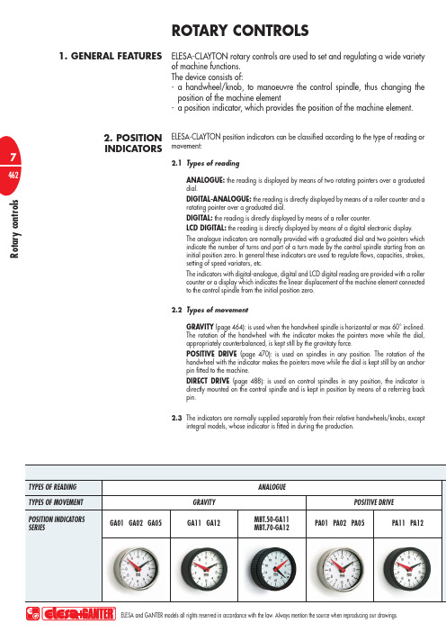
R o t a r y c o n t r o l sELESA-CLAYTON rotary controls are used to set and regulating a wide variety of machine functions.The device consists of:- a handwheel/knob, to manoeuvre the control spindle, thus changing the position of the machine element- a position indicator, which provides the position of the machine element.ELESA-CLAYTON position indicators can be classified according to the type of reading or movement:2.1 Types of reading ANALOGUE: the reading is displayed by means of two rotating pointers over a graduated dial.DIGITAL-ANALOGUE: the reading is directly displayed by means of a roller counter and a rotating pointer over a graduated dial.DIGITAL: the reading is directly displayed by means of a roller counter.LCD DIGITAL: the reading is directly displayed by means of a digital electronic display.The analogue indicators are normally provided with a graduated dial and two pointers which indicate the number of turns and part of a turn made by the control spindle starting from an initial position zero. In general these indicators are used to regulate flows, capacities, strokes, setting of speed variators, etc.The indicators with digital-analogue, digital and LCD digital reading are provided with a roller counter or a display which indicates the linear displacement of the machine element connected to the control spindle from the initial position zero.2.2 Types of movementGRAVITY (page 464): is used when the handwheel spindle is horizontal or max 60° inclined. The rotation of the handwheel with the indicator makes the pointers move while the dial, appropriately counterbalanced, is kept still by the gravitaty force.POSITIVE DRIVE (page 470): is used on spindles in any position. The rotation of the handwheel with the indicator makes the pointers move while the dial is kept still by an anchor pin fitted to the machine.DIRECT DRIVE (page 488): is used on control spindles in any position, the indicator is directly mounted on the control spindle and is kept in position by means of a referring back pin.2.3 The indicators are normally supplied separately from their relative handwheels/knobs, exceptintegral models, whose indicator is fitted in during the production.ROTARY CONTROLS1. GENERAL FEATURES2. POSITIONINDICATORSR o t a r y c o n t r o l s3. HOW TO SELECT THE ROTARY CONTROL4. SPECIALEXECUTIONS3.1 Choice of the type of reading (see 2.1). Establish if is necessary to display a number of turnsor a linear displacement. For the first application choose an analogue indicator. For the second one choose a digital-analogue, digital or LCD digital indicator.3.2 Establish the indicator and the spindle position on which depends the choice of the requestedmovement: gravity, positive drive or direct drive (see 2.2).3.3 Establish the required ratio for analogue types or the reading after one revolution for thefollowing types: digital-analogue, digital and LCD digital.3.4 Establish the direction of rotation. For clockwise increasing readings (right) = D. For anticlockwiseincreasing readings (left) = S.3.5 Consider the conditions of use of the handwheel i.e. outdoors, vibrations, corrosive environments,etc. See the complete data on the page of the chosen indicator.3.6 Choose the appropriate handwheel/knob for the application considering the diameter and the grip required to transmit the necessary torque. Other factors to take into consideration are the control spindle diameter and whether a handle is required for quick operations.4.1 The ELESA-CLAYTON position indicators standard range available on this catalogue satisfiesmost applications. Changes to adapt the indicator to particular applications are possible, for example: - special dials for indicators with analogue or digital-analogue reading, on customers indications- stainless steel metal parts for application on machines and equipment where laws or particular hygienic and environmental factors make it mandatory to use corrosion resistant materials- gravity indicators with analogue reading with glycerine-filling for high vibration applications, which may interfere with the reading, or to avoid condensation on the indicator window- special ratio on request and for sufficient quantities, developed by ELESA TechnicalDepartment.R o t a r y c o n t r o l s1.1 Suitable for use on control spindles with horizontal or max 60° inclined position.1.2 The movement is housed in a sealed case (fig. 1). It consists of a counterweight system, fittedon a precision ballrace, which rotates on a central spindle integral with the indicator case, fitted on the handwheel/knob. At the end of the spindle there is a red pointer, which rotates with the handwheel/knob. A series of gears with different ratios transmits the rotation of the spindle to a black pointer. On the counterweight is also fixed a graduated dial. If the indicator is fitted on spindles with horizontal position (or max 60° inclined) the dial is kept still by the gravity force and the pointers rotate over it when the handwheel/knob turns.2. RATIOS3. CHOICE OF THE INDICATOR RATIOFig.2GRAVITY INDICATORS1. FEAUTURES2.1 Each complete turn of the big pointer (red) corresponds to a fraction of turn of the small pointer(black). The number of turns of the red pointer to make the black pointer to carry out one complete turn is the ratio of the indicator. Example: a ratio of 12:1 means that to 12 turns of the red pointer correspond to a complete turn of the black pointer (fig. 2).12 turns of the handwheel cover the entire setting range. For each turn of the handwheel, the black pointer indicates 1/12 of the entire dial.3.1 Set the control spindle to the initial or referring position.3.2 Count the number of turns of the control spindle to cover the entire setting range.3.3 The result of this operation is the ratio. Should it not correspond to a standard ratio, choosethe next highest one.Fig.1IZN.MBT.VHT.VRTP .475476477478•R o t a r y c o n t r o l s3.4 For an optimal dial reading, and therefore for a more precise reading we recommend tochoose a ratio which is as near as possible to the handwheel turns required to cover the entire setting range. For instance, if 11 turns are required, the ratio 12:1 is the most convenient, because 11/12 of the available graduation will be used. If 24:1 ratio would be chosen, only 11/24 of the graduation would be used and reading would be less accurate.3.5 Indicators with standard ratios are normally on stock to suit most requirements.4.1 Dials are available for all standard ratios in both clockwise (D) or anticlockwise (S)configurations.4.2 Standard dials give a number which can be translated by means of conversion tables to thevalue of the set-up executed.4.3 be supplied to have a direct reading.5.1 however used on spindles max 60° inclined, but the accuracy decreases as the angle inclination a ° increases (fig. 3).6.1 If the hole of the handwheel/knob hub or boss needs to be reamed for coupling to the controlspindle, please refer to the handwheel/knob relevant page for further details and advice.6.2 Assembly of the indicators to handwheels/knobs: - couple the handwheel to the control spindle by means of a pin or a grub screw - set the control spindle to the initial or referring position, by rotating the handwheel - turn the indicator, by keeping it in the hands, until the pointers are in zero position- fit the zeroed indicator into the handwheel/knob and uniformly tighten the radial securing screws with a moderate torque to prevent distortion of the indicator case and thus locking the movement.6.3 Assembly of integral indicators (built-in in the handwheel): - set the control spindle to the initial or referring position- turn the indicator, by keeping it in the hands, until the pointers are in zero position- couple the integral indicator to the control spindle by tightening the grub screw, after checking that spindle and indicator are in zero position.4. DIALS5. ACCURACY6. ASSEMBLY INSTRUCTIONSExample of gravity indicator descriptionFig.3VD+I VDC.VDSC+I VAD.479480482484Electronic spindle position indicator system• APPLICATIONThe system provides an efficient electronic check of manual drive shafts with considerably lower costs than with completely automatized systems.• EASY TO USEThe system can be used to set a number of spindles quickly (set-up profile) and in a completely guided way.• SET-UP TIME REDUCTIONThe field tests carried out on machines provided with DE51 electronic indicators, give a set-up time reduction by 30÷40% compared to those with the traditional mechanical position indicators.• ABSOLUTE OPTICAL ENCODERDE51 measuring system is based on an absolute optical multi-turn encoder and it is not affected by magnetic fields. Therefore it is able to guarantee perfect operation, even in the presence of electric motors. Thanks to the long-life lithium battery (more than 10 years of life-espectancy) spindle positioning variations can be registered even when the power supply is switched off and it prevents the loss of the preset values in case of an electrical power failure.• SAFETYThe connection of DE51 electronic indicators directly to the PLC of the machine, functions also as a safety system, preventing the machine fromstarting to work if the set-up profile is not completed.• RETROFITThe small dimensions of DE51 indicators allow the retrofit of the existingmachines, without any structural modifications.。
数控机床电子手轮工作原理及故障分析

设备管理与维修2021翼1(上)数控机床电子手轮工作原理及故障分析关进良,岳维超,李术平,刘松,张华鹏(首都航天机械有限公司,北京100076)摘要:从数控机床PMC 地址信号、机床参数、硬件连接以及地址分配等方面介绍了FANUC 数控系统电子手轮的工作原理,结合工作中具体的故障诊断实例,从原理上分析导致故障的各种原因和排除故障的过程,并给出相应的解决方案。
关键词:电子手轮;PMC ;参数;维修实例中图分类号:TG659文献标识码:BDOI :10.16621/ki.issn1001-0599.2021.01.240引言数控机床电子手轮(Manual Pulse Generator ,MPG ),又称为手摇脉冲发生器,简称“手轮”或“手脉”。
它是通过手摇脉冲编码器所产生的脉冲信号来控制机床各伺服轴的运动,脉冲的频率和脉冲个数分别控制轴运动的速度和位移。
手轮是数控机床实现刀具微动和工作台运动控制等功能不可或缺的部件(如:工件对刀、几何精度检测等),直接影响着机床的实用性。
1典型电子手轮介绍数控机床手动进给一般有JOG (手动)、手动快速和手轮3种方式,当对进给轴进行手动位置控制或精准微量调整时,一般选择手轮方式。
常见的手轮分为两种:单个手摇脉冲发生器(一般直接嵌入在操作面板上)和手持型手轮(也称为外挂式手轮),主要研究的是FANUC 数控机床的手持型手轮。
典型的手持型手轮除脉冲发生器外,一般还配有轴选开关(3耀6轴)、倍率开关(伊1,伊10,伊100)、手轮使能键和指示灯等。
使用手轮时,首先把机床的方式选择开关调到手轮方式,按下手轮使能键,指示灯亮,使轴选开关选定在某个轴,并选择某个倍率,当转动脉冲发生器时即可实现机床各轴的手轮进给,每当发出1个脉冲,机床便可移动相对应倍率的移动量。
需要注意的是,手摇脉冲发生器的旋转速度不要太快,最好应控制在5r/s 以下,否则可能出现当手轮不旋转时机床还在继续移动的情况。
norelem 手轮 DIN 950 产品说明书
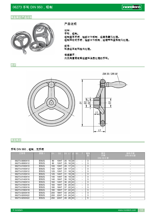
定位孔
140 16H7 36 19 39 - - 3
定位孔
160 14H7 36 20 40 - - 3
定位孔
160 16H7 36 20 40 - - 3
定位孔
180 16H7 37 22 43 - - 3
定位孔
180 18H7 37 22 43 - - 3
定位孔
200 18H7 43 24 45 - - 3
定位孔
400 34H7 65 38 63 - - 5
定位孔
500 34H7 79 45 72 - - 5
定位孔
500 40H7 79 45 72 - - 5
带开槽的定位孔 80 10H7 25 16 29 3 11,4 3
带开槽的定位孔 80 12H7 25 16 29 4 13,8 3
带开槽的定位孔 100 10H7 29 17 33 3 11,4 3
固定 手柄 DIN 39 E 型
-
旋转手柄 DIN 98 E型
-
© norelem
1/3
06273 手轮 DIN 950,铝制
商品概述
订货号
06273-0250X26 06273-0315X26 06273-0315X30 06273-0400X30 06273-0400X34 06273-0500X34 06273-0500X40 06273-1080X10 06273-1080X12 06273-1100X10 06273-1100X12 06273-1125X12 06273-1125X14 06273-1140X14 06273-1140X16 06273-1160X14 06273-1160X16 06273-1180X16 06273-1180X18 06273-1200X18 06273-1200X22 06273-1250X22 06273-1250X26 06273-1315X26 06273-1315X30 06273-1400X30 06273-1400X34 06273-1500X34 06273-1500X40 06273-2080X10 06273-2080X12 06273-2100X10 06273-2100X12 06273-2125X12 06273-2125X14 06273-2140X14 06273-2140X16 06273-2160X14 06273-2160X16 06273-2180X16 06273-2180X18 06273-2200X18 06273-2200X22 06273-2250X22 06273-2250X26 06273-2315X26 06273-2315X30 06273-2400X30 06273-2400X34 06273-2500X34 06273-2500X40 06273-3080X10 06273-3080X12 06273-3100X10 06273-3100X12 06273-3125X12 06273-3125X14 06273-3140X14 06273-3140X16 06273-3160X14 06273-3160X16 06273-3180X16 06273-3180X18 06273-3200X18
電控操作手冊说明书

電控操作手冊匯出日期:2023-05-10修改日期:2020-10-03英文文件 English Document: Electronics Operation Manual.前言一般操作手冊僅說明終端客戶會用到的畫面及按鍵,但電控人員需要的各類診斷、參數設定及系統管理等功能均無相關內容,故有此文件的誕生。
本文件以按鍵架構為基礎,逐一說明各按鍵的功能,最後另加上"附錄"一節,補充說明沒有按鍵可操作的功能,或者是較重大的相容性異動。
(此文件編輯時,以10.116.24J, 11MA / 10.118.12O 22MA, 八鍵系統為基準)••••••••••••••1 PLC 狀態1.1 PLC 狀態路徑八鍵:F10 下一頁>F1 PLC 狀態五鍵:F10 下一頁>F1 PLC 狀態說明此區畫面可用來查詢所有PLC 相關元件的狀態,包含I 、O 、C 、S 、A 、R 、Timer 、Counter 等,同時還能檢視、診斷、編輯階梯圖的內容。
1.2 I/O Bit1.2.1 I/O Bit路徑八鍵:F10 下一頁>F1 PLC 狀態>F1 I/O Bit 五鍵:F10 下一頁>F1 PLC 狀態>F1 I/O Bit說明此頁面可查詢I/O Bit 目前的狀態。
0表示該I/O Bit 為OFF ,FF 表示該I/O Bit 為ON 。
操作方式直接按下I/O Bit 這按鍵,即可進行I/O Bit 頁面的切換。
I Bit畫面••••••••O Bit 畫面1.3 PLC C Bit1.3.1 PLC C Bit路徑八鍵:F10 下一頁>F1 PLC 狀態>F2 PLC C Bit 五鍵:F10 下一頁>F1 PLC 狀態>F2 PLC C Bit說明此頁面可查詢C Bit 目前的狀態。
0表示該C Bit 為OFF ,FF 表示該C Bit 為ON 。
SH-BP4Y物理面板使用说明书20192022
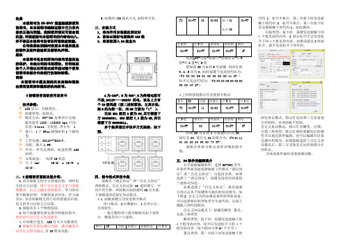
免责本说明书为SH-BP4Y液晶触摸屏使用说明书,在本说明书编制过程中已力求内容的正确与完整,实际使用情况可能会因机型、环境差别与本说明书的内容有出入,并不保证本说明书没有任何错误或错漏。
公司保留权利随时变更本手册所提及的硬件及软件规格而无需事先声明。
版权本说明书包含的所有内容均受版权法的保护,未经公司的书面授权,任何组织和个人不得以任何形式或手段对整个使用说明书和部分内容进行复制和转载。
商标本说明书中提及到的其他商标和徽标由拥有该商标和徽标的机构所有。
4按键语音面板使用说明书一.技术参数:✧LED显示:无极调光。
✧按键类型:按钮式。
✧通讯方式:RS-485标准串行总线,通讯速率1200~115200 bps可设,长度:8 bits,无校验,停止位 1 ✧接口:1个5Pin接线座和1个拨码盘✧工作电源:DC12V--DC24V。
✧功耗:最大1.5W。
✧外壳:外壳金属铝,底盒阻燃ABS材质。
✧安装底盒:标准86底盒✧尺寸(mm) 86(H) x 86(W) x38(D)。
二.4按键语音面板功能介绍:1.语音面板支持中文普通识别,同时也支持方言识别,用户可以自定义学习训练唤醒词、自定义输出控制指令,学习的内容不限制语种,不限制说话内容。
学习成功后,语音面板既支持已有的普通话识别,也支持学习后的方言识别。
2.面板具有4个物理按钮。
3.每个按键都有固定指令和被控指令,同时也可以自定义发送指令。
4.中间镂空透光,LED灯可以无极调光5.面板具有靠近感应功能,感应触发可以自定义指令输出,有3D震动功能。
6.标准的485通讯方式,波特率可变。
三.安装方式1, 将扣件用安装螺丝固定好2,按标示接好电源线和485线3,将面板筛入86底盒内A为485+,B为485-,R为终端电阻可不接,DC12V——DC24V供电,设备上方有个ID拨码盘(按二进制算法,左高右低,标8的为第一位,向ON方拨为“1”),比如ID1就把8拨为ON,其它都拨下方00000001,ID3就把7,8拨为ON,其它都拨下方00000011。
- 1、下载文档前请自行甄别文档内容的完整性,平台不提供额外的编辑、内容补充、找答案等附加服务。
- 2、"仅部分预览"的文档,不可在线预览部分如存在完整性等问题,可反馈申请退款(可完整预览的文档不适用该条件!)。
- 3、如文档侵犯您的权益,请联系客服反馈,我们会尽快为您处理(人工客服工作时间:9:00-18:30)。
面板式电子手轮使用说明书
产品描述
安装部位尺寸Φ50.8mm ,超薄轻巧设计,金属面板,轻动手感清晰。
适用于NC 线板等手动脉冲输入,数控机床,印刷机械零位补正和分割
输出波形与信号位置精度
90°相位差两信号与Z 信号,从轴端看,顺时针旋转(CW
)时的波形图:
刻度盘刻线形停顿在斜线的范围内,与其配合的设备必须任其停顿位置。
接线表
安装尺寸
技术参数
郑重声明
未经本人允许,任何人不得以任何形式转载。
本材料仅供购买我司产品的广大客户使用,以及广大技术人员参考。
任何侵权的行为我们追究其法律责任!
日照精诚自动化有限公司宣。
