ASTM D695 塑料 压缩
塑胶测试标准

检测项目 检测标准
ASTM D2240-05 用硬度计测定橡胶硬度的试验方法 GB/T 2411-1980 塑料邵氏硬度试验方法 ISO 868:2003 塑料 塑料和硬橡胶 用硬度计测定压痕硬度(肖氏硬 度) DIN 53505 橡胶、弹性体和塑料检验 邵氏A和邵氏D硬度试验 ASTM D785-03 塑料与电绝缘材料的洛氏硬度的试验方法
压缩试验中试 样所承受的最 大压缩应力 线性范围内压 缩应力与压缩 应变的比值
性 能
撕裂强度
ASTM D1004-03 塑料薄膜和片材抗初始撕裂试验方法 GB/T 1130-1991 塑料直角撕裂性能试验方法 GB/T 16578-1996 塑料薄膜和薄片耐撕裂性能试验方法 裤形撕 裂法 ISO 6383-1:2004 塑料 薄膜和薄板 耐撕裂性的测定 第1部分:裤 型撕裂法 DIN 53356 人造革和类似的平面织物的检验.连续撕裂试验 ASTM D751-2000 涂层织物的测试方法 GB/T 2792-1998 压敏胶粘带180° 剥离强度试验方法 DIN 53357-1982 塑料布和塑料薄膜的检验.层间分离试验
击 试 验
落锤冲击 落球冲击 验方法:落球法 (/) PV 3905:1972 大众标准 有机材料 落球试验
GB/T 14485-1993 工程塑料硬质塑料板材及塑料件耐冲击性能试
落镖冲击
ASTM D1709-03 自由落镖法测定塑料薄膜抗冲击性能的试验方 法 GB 9639-1988 塑料薄膜和薄片抗冲击性能试验方法 自由落镖 法 SAE J400
在规定的受力 及变形条件 下,测出其显 示脆性破坏时 的温度
燃烧特性 (mm/min)
ASTM D5132-04 机动车宿营舱中用的柔性泡沫和橡胶材料的横 向燃烧速率的测试方法 GB/T 2408-1996 塑料燃烧性能试验方法 水平法和垂直法
塑胶测试标准 (3)
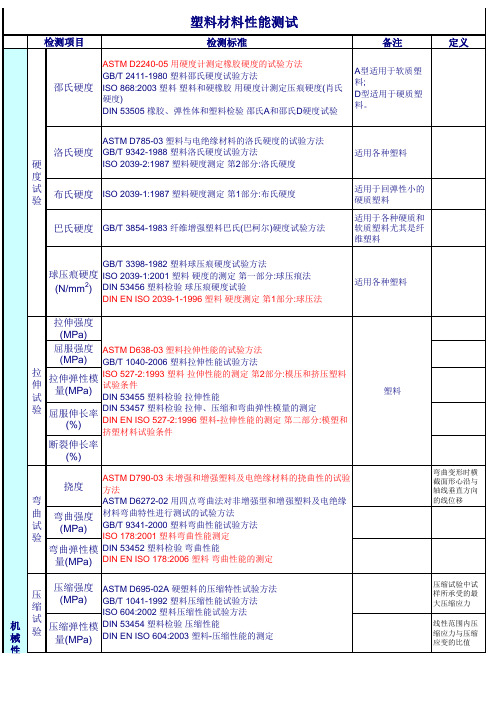
巴氏硬度 GB/T 3854-1983 纤维增强塑料巴氏(巴柯尔)硬度试验方法
适用各种塑料
适用于回弹性小的 硬质塑料 适用于各种硬质和 软质塑料尤其是纤 维塑料
GB/T 3398-1982 塑料球压痕硬度试验方法
球压痕硬度 ISO 2039-1:2001 塑料 硬度的测定 第一部分:球压痕法
(N/mm2) DIN 53456 塑料检验 球压痕硬度试验
载荷下挠曲温 度
ASTM D648-06 弯曲载荷下塑料变形温度的测定 GB/T 1634.2-2004 塑料 载荷下挠曲温度的测定 第2部分:塑料和 硬橡胶 ISO 75-2:2004 塑料 载荷下挠曲温度的测定 第2部分:塑料和硬橡 胶 DIN 53461 塑料检验 热变形温度的测定 DIN EN ISO 75-2:2004 塑料 载荷下挠曲温度的测定 第2部分:塑 料和硬橡胶塑料
气味试验 (等级)
SAE J1351 GM 9130P GME 60276 通用标准 气味测试 PV 3900-2000 大众标准 气味测试 TSM0505G-2005 丰田标准 FLTM BO 131-01 ES-X 60250 MS 300-34 EDS-T-7603
甲醛含量 (mg/kg)
GME 60271 通用标准 甲醛含量 PV3925 大众标准 甲醛含量 SQR.04.096
ASTM D256-06a 测定塑料悬臂梁试样抗摆锤冲击性能方法
冲 击
悬臂梁冲击 GB/T 1843-1996 塑料悬臂梁冲击试验方法
ISO 180:2001 塑料 悬臂梁冲击性能的测定
试
验 落锤冲击
落球冲击 (/)
GB/T 14485-1993 工程塑料硬质塑料板材及塑料件耐冲击性能试 验方法:落球法 PV 3905:1972 大众标准 有机材料 落球试验
常见塑料物性的检测及标准

常见塑料物性的检测及标准流动系数(1)测试的标准:ASTM D1238(2)常用的测试标准的量测仪器是溶液指数计(Melt Indexer).(3)流动系数检测方法:是一种表示塑胶材料加工时的流动性的数值。
它是美国量测标准协会(ASTM)根据美国杜邦公司(Du Pont)惯用的鉴定塑料特性的方法制定而成,其测试方法是先让塑料粒在一定时间(10分钟)内、一定温度及压力(各种材料标准不同)下,融化成塑料流体,然后通过一直径为2.1mm圆管所流出的克(g)数。
其值越大,表示该塑胶材料的加工流动性越佳,反之则越差。
(4)测试的具体操作过程是:将待测高分子(塑料)原料置入小槽中,槽末接有细管,细管直径为2.095mm,管长为8mm。
加热至某温度后,原料上端藉由活塞施加某一定重量向下压挤,量测该原料在10分钟内所被挤出的重量,即为该塑料的流动指数。
有时您会看到这样的表示法?MI25g/10min,它表示在10分钟内该塑料被挤出25克。
一般常用塑料的MI值大约介于1~25之间。
MI愈大,代表该塑料原料粘度愈小及分子重量愈小,反之则代表该塑料粘度愈大及分子重量愈大。
收缩率•测试的标准:ASTM D955•塑胶制品经冷却、固化并脱模成形后,其尺寸与原模具尺寸之差的百分比。
(3)因结构不同的关系,结晶性塑料与非结晶性塑料的收缩率存在明显的差异。
一般地,结晶性塑料的收缩率比非结晶性塑料的收缩率大上好几倍(如下表所示)。
同时有添加玻璃纤维或其它强化剂的塑胶材料,其收缩率可降低好几倍。
影响成型收缩的因素有热收缩、结晶度(热塑性)或硬化度(热固性)、弹性回复、分子配向、与成型条件等因素。
<1>热塑性塑料塑料名称成形收缩率(%)塑料名称成形收缩率(%)塑料名称成形收缩率(%)ABS0.3~0.8PA0.6~2.5POM0.8~3.5 AS0.2~0.7PA-60.5~2.2PP 1.0~2.5 CA0.3~0.8PA-660.5~2.5PPO0.5~0.7 CAB0.4~0.5PA-610 1.2PPS0.6~1.4 CAP1PA-612 1.1PS0.2~1.0 CP0.4~0.5PA-11 1.2PVA0.5~1.5 EC0.4~0.5PA-120.3~1.5PVAC0.5~1.5 EPS0.4PAR0.8~1.0PVB0.5~1.5 FEP 3.0~4.0PBT 1.3~2.4硬质PVC0.1~0.5FRP0.1~0.4PC0.4~0.7软质PVC 1.0~5.0 EVA0.5~1.5PCTFE0.2~2.5PVCA 1.0~5.0 HDPE 1.2~2.2PE0.5~2.5PVDC0.5~2.5 HIPS0.2~1.0PET 2.0~2.5PVFM0.5~1.5 LCP0.1~1.0PES0.5~1.0SAN0.2~0.6 LDPE 1.5~3.0PMMA0.2~0.8SB0.2~1.0<2>热固性塑料塑料名称成形收缩率(%)塑料名称成形收缩率(%) EP0.1~0.5SP0.0~0.5MF0.5~1.5UF0.6~1.4PDAP0.1~0.5UP0.1~1.2PF0.4~0.9DAP0.1~0.5PU0.6~0.8BMC0.0~0.2热膨胀系数•测试的标准:ASTM D696•塑料加热时尺寸膨胀的比率•由于一般塑料的热膨胀系数比金属大2~10倍,因此在设计模具、塑料与金属并用的器具、塑料的钳核物时,必须详加考虑,以防止因内部应力而造成产品的龟裂变形。
聚苯乙烯 压缩强度 不合格 -回复

聚苯乙烯压缩强度不合格-回复聚苯乙烯是一种常用的塑料材料,具有低成本、耐化学品腐蚀、绝缘性能好等特点,广泛应用于建筑、包装、电子等领域。
然而,在某些情况下,聚苯乙烯的压缩强度可能不符合要求,这会对其应用造成一定的影响。
本文将一步一步回答关于聚苯乙烯压缩强度不合格的问题。
第一步:了解聚苯乙烯的压缩强度标准聚苯乙烯的压缩强度是指材料在一定条件下承受垂直压力时产生的最大压力。
根据不同的应用领域和需求,对聚苯乙烯的压缩强度有不同的标准要求。
常见的测试方法包括ASTM D695、ISO 604等,这些方法可以测量样品在一定应变速率下的变形性能和耐冲击性能。
第二步:了解聚苯乙烯压缩强度不合格的原因聚苯乙烯的压缩强度不合格可能由多种原因导致,包括原料质量差、生产工艺不当、设计不合理等。
原料质量差指的是聚苯乙烯中存在杂质、气泡等缺陷,这会导致材料的力学性能下降。
生产工艺不当包括温度、压力、时间等参数设置不当,可能导致材料中的有机物挥发不完全、晶体分布不均匀等问题。
设计不合理指的是聚苯乙烯制品的结构形式、尺寸等不符合使用要求。
第三步:分析聚苯乙烯压缩强度不合格的影响聚苯乙烯的压缩强度不合格会对其应用产生一定的影响。
首先,不合格的材料可能导致使用过程中的变形或破裂。
例如,在建筑领域中,聚苯乙烯常用于保温层材料,如果其压缩强度不合格,可能会导致保温层的变形或破裂,降低保温效果。
其次,压缩强度不合格也可能影响产品的整体坚固性。
例如,在包装领域中,聚苯乙烯常用于制作轻型包装盒,如果其压缩强度不合格,可能会导致包装盒在叠放或运输过程中受力不均,造成损坏。
此外,聚苯乙烯的压缩强度不合格还可能对产品的寿命和可靠性产生负面影响。
第四步:解决聚苯乙烯压缩强度不合格的方法针对聚苯乙烯压缩强度不合格的问题,可以采取以下几种方法进行解决。
首先,优化原料的选择和处理过程,确保材料质量符合要求。
例如,可以通过增加原料的纯度、筛选杂质等方式来改善原料质量。
astm塑胶peek标准
astm塑胶peek标准
ASTM塑胶PEEK标准是由ASTM国际标准组织制定的一系列适用于聚醚醚酮(PEEK)塑料材料的测试方法和规范。
以下是一些常见的ASTM塑胶PEEK标准:
1. ASTM D638:这个标准规定了PEEK塑料材料的拉伸性能测试方法,包括弹性模量、抗拉强度、断裂伸长率等指标的测定。
2. ASTM D790:这个标准规定了PEEK塑料材料的弯曲性能测试方法,包括弯曲模量、弯曲强度等指标的测定。
3. ASTM D695:这个标准规定了PEEK塑料材料的压缩性能测试方法,包括压缩弹性模量、压缩强度等指标的测定。
4. ASTM D256:这个标准规定了PEEK塑料材料的冲击强度测试方法,包括缺口冲击强度等指标的测定。
5. ASTM D6384:这个标准规定了PEEK塑料材料的热分析测试方法,包括热失重、差热分析等指标的测定。
6. ASTM D785:这个标准规定了PEEK塑料材料的洛氏硬度测试方法。
以上仅是一些常见的ASTM塑胶PEEK标准,实际应用中还有其他相关的标准。
根据具体需求,可以选择适用的标准进行测试和评估。
复合材料常见的测试内容及相应标准
复合材料常见的测试内容及相应标准通过广泛的标准化和非标准化机械测试可以来复合材料的一些性能,常见的测试主要包括拉伸、压缩、弯曲、剪切、冲击和疲劳等等。
复合材料的机械测试必须使用能够在负载控制、位移控制和应变控制等方面进行测试的材料测试系统。
由于复合材料典型的各向异性特性,测试这些材料面临的主要挑战之一是需要开发各种夹具以提供在不同条件下测试材料的各种方法。
在本文中简要介绍了一些常见测试内容及相应的测试标准。
单向拉伸试验(ASTM D638,ISO 527)单向拉伸试验中的应力(ζ)计算公式如下:ζ=材料样品的荷载/面积应变(ε)的计算公式为:ε=δl(长度变化)/l(初始长度)曲线(E)的初始线性部分的斜率为杨氏模量,由下式给出:E=(ζ2-ζ1)/(ε2-ε1)4点弯曲弯曲试验(ASTM D6272)四点弯曲试验测试可提供弯曲弹性模量、弯曲应力和弯曲数据。
该测试与三点弯曲弯曲试验非常相似。
主要区别在于,增加了第四个用于施加载荷的鼻梁部分,两个载荷点之间的梁部分处于最大应力下。
在三点弯曲试验中,只有加载鼻下的梁部分处于应力状态。
这种布置有助于测试高刚度材料,如注入陶瓷的聚合物,其中最大应力下缺陷的数量和严重程度与材料的弯曲强度和裂纹萌生直接相关。
与三点弯曲弯曲试验相比,的四点弯曲弯曲测试在两个加载销之间区域中没有剪切力。
泊松比试验(ASTM D3039)泊松比是用于结构设计中的最重要参数之一,其中需要考虑因施加力而导致的所有尺寸变化,特别是3D打印材料。
对于该试验方法,泊松比仅由单轴应力产生的应变获得。
该测试通过向试样施加张力并测量试样在应力下的各种性能来进行测试。
两个应变计以0度和90度与试样连接,以测量横向应变和线性应变。
横向应变与线性应变之比可提供泊松比。
平面压缩试验(ASTM D695)当产品在压缩载荷条件下运行时,3D打印材料的压缩性能非常重要。
测试在垂直于面板平面的方向上进行,因为核心将放置在结构夹层结构中。
塑料规整填料的抗压缩测试
塑料规整填料的抗压缩测试摘要塑料规整填料是一种新型的环保填料,具有降解速度快、耐酸碱、重量轻等特点,被广泛应用于水处理、废气处理、土壤修复等领域。
本文紧要介绍了塑料规整填料的抗压缩测试方法以及测试结果分析。
引言在污水处理、废气处理、土壤修复等领域,填料是一种常见的材料,用于实现分别、脱水、杀菌、吸附等功能。
传统的填料紧要使用石英砂、陶瓷球等材料,但这些填料存在侧重量大、易磨损、易产生二次污染等问题。
因此,近年来,研发出一种新型的填料:塑料规整填料。
塑料规整填料是由高密度聚乙烯制成的球形粒子,具有降解速度快、耐酸碱、重量轻等优点,被广泛应用于水处理、废气处理、土壤修复等领域。
本文将介绍接受ASTM D695标准测试方法,测试塑料规整填料的抗压缩性能,并对测试结果进行分析。
试验方法材料准备•塑料规整填料•纯洁水试验仪器•电子试验机•压缩模具•计算机试验步骤1.取确定质量的塑料规整填料(5克、10克、20克等),并将其放在试验机上的压缩模具中;2.将压缩模具放在试验机上,调整加载速率为2mm/min;3.启动试验机开始测试,记录下每次加载的压强以及相应的变形量;4.当填料失去抗压本领,变形量持续加添,不再随着加载而增长时,停止试验。
数据处理1.对压缩试验的结果进行统计;2.计算抗压强度、压缩模量等指标;3.绘制抗压强度与变形量的曲线,并进行分析。
试验结果抗压强度通过试验数据计算,可以得到填料的抗压强度如下表所示。
水量(mL)塑料规整填料质量(g)抗压强度(MPa)30 5 1.530 10 1.430 20 1.3压缩模量通过试验数据计算,可以得到填料的压缩模量如下表所示。
水量(mL)塑料规整填料质量(g)压缩模量(MPa)30 5 0.830 10 0.730 20 0.6抗压强度与变形量的曲线将抗压强度与变形量的数据绘制成曲线图如下:抗压强度与变形量曲线图抗压强度与变形量曲线图结论从测试结果可以看出,塑料规整填料具有较好的抗压强度和压缩模量,能充分实际应用的需要。
ASTM D695-2010
Designation:D695–10Standard Test Method forCompressive Properties of Rigid Plastics1This standard is issued under thefixed designation D695;the number immediately following the designation indicates the year of original adoption or,in the case of revision,the year of last revision.A number in parentheses indicates the year of last reapproval.A superscript epsilon(´)indicates an editorial change since the last revision or reapproval.This standard has been approved for use by agencies of the Department of Defense.1.Scope*1.1This test method covers the determination of the me-chanical properties of unreinforced and reinforced rigid plas-tics,including high-modulus composites,when loaded in compression at relatively low uniform rates of straining or loading.Test specimens of standard shape are employed.This procedure is applicable for a composite modulus up to and including41,370MPa(6,000,000psi).1.2The values stated in SI units are to be regarded as the standard.The values in parentheses are for information only. N OTE1—For compressive properties of resin-matrix composites rein-forced with oriented continuous,discontinuous,or cross-ply reinforce-ments,tests may be made in accordance with Test Method D3410/ D3410M.1.3This standard does not purport to address all of the safety concerns,if any,associated with its use.It is the responsibility of the user of this standard to establish appro-priate safety and health practices and determine the applica-bility of regulatory limitations prior to use.A specific precau-tionary statement is given in13.1.N OTE2—This test method is technically equivalent to ISO604.2.Referenced Documents2.1ASTM Standards:2D618Practice for Conditioning Plastics for TestingD638Test Method for Tensile Properties of PlasticsD883Terminology Relating to PlasticsD3410/D3410M Test Method for Compressive Properties of Polymer Matrix Composite Materials with Unsupported Gage Section by Shear LoadingD4000Classification System for Specifying Plastic Materi-alsD5947Test Methods for Physical Dimensions of Solid Plastics SpecimensE4Practices for Force Verification of Testing MachinesE83Practice for Verification and Classification of Exten-someter SystemsE691Practice for Conducting an Interlaboratory Study to Determine the Precision of a Test Method2.2ISO Standard:3ISO604Plastics—Determination of Compressive Proper-ties3.Terminology3.1General—The definitions of plastics used in this test method are in accordance with Terminology D883unless otherwise indicated.3.2Definitions:3.2.1compressive deformation—the decrease in length pro-duced in the gage length of the test specimen by a compressive load.It is expressed in units of length.3.2.2compressive strain—the ratio of compressive defor-mation to the gage length of the test specimen,that is,the change in length per unit of original length along the longitu-dinal axis.It is expressed as a dimensionless ratio.3.2.3compressive strength—the maximum compressive stress(nominal)carried by a test specimen during a compres-sion test.It may or may not be the compressive stress (nominal)carried by the specimen at the moment of rupture.3.2.4compressive strength at failure(nominal)—the com-pressive stress(nominal)sustained at the moment of failure of the test specimen if shattering occurs.3.2.5compressive stress(nominal)—the compressive load per unit area of minimum original cross section within the gage boundaries,carried by the test specimen at any given moment. It is expressed in force per unit area.1This test method is under the jurisdiction of ASTM Committee D20on Plastics and is the direct responsibility of Subcommittee D20.10on Mechanical Properties.Current edition approved April1,2010.Published April2010.Originally approved st previous edition approved in2008as D695-08.DOI: 10.1520/D0695-10.2For referenced ASTM standards,visit the ASTM website,,or contact ASTM Customer Service at service@.For Annual Book of ASTMStandards volume information,refer to the standard’s Document Summary page on the ASTM website.3Available from American National Standards Institute(ANSI),25W.43rd St., 4th Floor,New York,NY10036,.*A Summary of Changes section appears at the end of this standard. Copyright©ASTM International,100Barr Harbor Drive,PO Box C700,West Conshohocken,PA19428-2959,United States.3.2.5.1Discussion—The expression of compressive proper-ties in terms of the minimum original cross section is almost universally used.Under some circumstances the compressive properties have been expressed per unit of prevailing cross section.These properties are called“true”compressive prop-erties.3.2.6compressive stress-strain diagram—a diagram in which values of compressive stress are plotted as ordinates against corresponding values of compressive strain as abscis-sas.3.2.7compressive yield point—thefirst point on the stress-strain diagram at which an increase in strain occurs without an increase in stress.3.2.8compressive yield strength—normally the stress at the yield point(see also section3.2.11).3.2.9crushing load—the maximum compressive force ap-plied to the specimen,under the conditions of testing,that produces a designated degree of failure.3.2.10modulus of elasticity—the ratio of stress(nominal)to corresponding strain below the proportional limit of a material. It is expressed in force per unit area based on the average initial cross-sectional area.3.2.11offset compressive yield strength—the stress at which the stress-strain curve departs from linearity by a specified percent of deformation(offset).3.2.12percent compressive strain—the compressive defor-mation of a test specimen expressed as a percent of the original gage length.3.2.13proportional limit—the greatest stress that a material is capable of sustaining without any deviation from propor-tionality of stress to strain(Hooke’s law).It is expressed in force per unit area.3.2.14slenderness ratio—the ratio of the length of a col-umn of uniform cross section to its least radius of gyration.For specimens of uniform rectangular cross section,the radius of gyration is0.289times the smaller cross-sectional dimension. For specimens of uniform circular cross section,the radius of gyration is0.250times the diameter.4.Significance and Use4.1Compression tests provide information about the com-pressive properties of plastics when employed under conditions approximating those under which the tests are made.4.2Compressive properties include modulus of elasticity, yield stress,deformation beyond yield point,and compressive strength(unless the material merelyflattens but does not fracture).Materials possessing a low order of ductility may not exhibit a yield point.In the case of a material that fails in compression by a shattering fracture,the compressive strength has a very definite value.In the case of a material that does not fail in compression by a shattering fracture,the compressive strength is an arbitrary one depending upon the degree of distortion that is regarded as indicating complete failure of the material.Many plastic materials will continue to deform in compression until aflat disk is produced,the compressive stress(nominal)rising steadily in the process,without any well-defined fracture pressive strength can have no real meaning in such cases.4.3Compression tests provide a standard method of obtain-ing data for research and development,quality control,accep-tance or rejection under specifications,and special purposes. The tests cannot be considered significant for engineering design in applications differing widely from the load-time scale of the standard test.Such applications require additional tests such as impact,creep,and fatigue.4.4Before proceeding with this test method,reference should be made to the ASTM specification for the material being tested.Any test specimen preparation,conditioning, dimensions,and testing parameters covered in the materials specification shall take precedence over those mentioned in this test method.If there is no material specification,then the default conditions apply.Table1in Classification D4000lists the ASTM materials standards that currently exist.5.Apparatus5.1Testing Machine—Any suitable testing machine capable of control of constant-rate-of-crosshead movement and com-prising essentially the following:5.1.1Drive Mechanism—A drive mechanism for imparting to the movable cross-head member,a uniform,controlled velocity with respect to the base(fixed member),with this velocity to be regulated as specified in Section9.5.1.2Load Indicator—A load-indicating mechanism ca-pable of showing the total compressive load carried by the test specimen.The mechanism shall be essentially free from inertia-lag at the specified rate of testing and shall indicate the load with an accuracy of61%of the maximum indicated value of the test(load).The accuracy of the testing machine shall be verified at least once a year in accordance with Practices E4.5.2Compressometer—A suitable instrument for determin-ing the distance between twofixed points on the test specimen at any time during the test.It is desirable that this instrument automatically record this distance(or any change in it)as a function of the load on the test specimen.The instrument shall be essentially free of inertia-lag at the specified rate of loading and shall conform to the requirements for a Class B-2 extensometer as defined in Practice E83.N OTE3—The requirements for extensometers cited herein apply to compressometers as well.5.3Compression Tool—A compression tool for applying the load to the test specimen.This tool shall be so constructed that loading is axial within1:1000and applied through surfaces that areflat within0.025mm(0.001in.)and parallel to each other in a plane normal to the vertical loading axis.Examples of suitable compression tools are shown in Fig.1and Fig.2. 5.4Supporting Jig—A supporting jig for thin specimens is shown in Fig.3and Fig.4.5.5Micrometers—Suitable micrometers,reading to0.01 mm or0.001in.for measuring the width,thickness,and length of the specimens.6.Test Specimens6.1Unless otherwise specified in the materials specifica-tions,the specimens described in6.2and6.7shall be used. These specimens may be prepared by machiningoperationsfrom materials in sheet,plate,rod,tube,or similar form,or they may be prepared by compression or injection molding of the material to be tested.All machining operations shall be done carefully so that smooth surfaces result.Great care shall be taken in machining the ends so that smooth,flat parallel surfaces and sharp,clean edges,to within 0.025mm (0.001in.)perpendicular to the long axis of the specimen,result.6.2The standard test specimen,except as indicated in 6.3-6.7,shall be in the form of a right cylinder or prism whoselength is twice its principal width or diameter.Preferred specimen sizes are 12.7by 12.7by 25.4mm (0.50by 0.50by 1in.)(prism),or 12.7mm in diameter by 25.4mm (cylinder).Where elastic modulus and offset yield-stress data are desired,the test specimen shall be of such dimensions that the slender-ness ratio is in the range from 11to 16:1.In this case,preferred specimen sizes are 12.7by 12.7by 50.8mm (0.50by 0.50by 2in.)(prism),or 12.7mm in diameter by 50.8mm (cylinder).6.3For rod material,the test specimen shall have a diameter equal to the diameter of the rod and a sufficient length to allow a specimen slenderness ratio in the range from 11to 16:1.6.4When testing tubes,the test specimen shall have a diameter equal to the diameter of the tube and a length of 25.4mm (1in.)(Note 4).For crushing-load determinations (at right angles to the longitudinal axis),the specimen size shall be the same,with the diameter becoming the height.N OTE 4—This specimen can be used for tubes with a wall thickness of 1mm (0.039in.)or over,to inside diameters of 6.4mm (0.25in.)or over,and to outside diameters of 50.8mm (2.0in.)or less.6.5Where it is desired to test conventional high-pressure laminates in the form of sheets,the thickness of which is less than 25.4mm (1in.),a pile-up of sheets 25.4mm square,with a sufficient number of layers to produce a height of at least 25.4mm,may be used.6.6When testing material that may be suspected of anisot-ropy,duplicate sets of test specimens shall be prepared having their long axis respectively parallel with and normal to the suspected direction of anisotropy.6.7Reinforced Plastics,Including High-Strength Compos-ites and High-Strength Composites and Highly Orthotropic Laminates —The following specimens shall be used for rein-forced materials,or for other materials when necessary to comply with the slenderness ratio requirements or to permit attachment of a deformation-measuring device.6.7.1For materials 3.2mm (1⁄8in.)and over in thickness,a specimen shall consist of a prism having a cross section of 12.7mm (1⁄2in.)by the thickness of the material and a length such that the slenderness ratio is in the range from 11to 16:1(Note 5).6.7.2For materials under 3.2mm (1⁄8in.)thick,or where elastic modulus testing is required and the slenderness ratio does not provide for enough length for attachment of a compressometer or similar device,a specimen conformingtoN OTE 1—Devices similar to the one illustrated have been successfully used in a number of different laboratories.Details of the device developed at the National Institute for Standards and Technology are given in the paper by Aitchinson,C.S.,and Miller,J.A.,“A Subpress for Compressive Tests,”National Advisory Committee for Aeronautics,Technical Note No.912,1943.FIG.1Subpress for CompressionTestsFIG.2CompressionToolFIG.3Support Jig for ThinSpecimenthat shown in Fig.5shall be used.The supporting jig shown in Fig.3and Fig.4shall be used to support the specimen during testing (Note 6).N OTE 5—If failure for materials in the thickness range of 3.2mm (1⁄8in.)is by delamination rather than by the desirable shear plane fracture,the material may be tested in accordance with 6.7.2.N OTE 6—Round-robin tests have established that relatively satisfactory measurements of modulus of elasticity may be obtained by applying a compressometer to the edges of the jig-supported specimen.6.8When testing syntactic foam,the standard test specimen shall be in the form of a right cylinder 25.4mm (1in.)in diameter by 50.8mm (2in.)in length.7.Conditioning7.1Conditioning —Condition the test specimens in accor-dance with Procedure A of Practice D618unless otherwise specified by contract or relevant ASTM material specification.Conditioning time is specified as a minimum.Temperature and humidity tolerances shall be in accordance with Section 7of Practice D618unless specified differently by contract or material specification.7.2Test Conditions —Conduct the tests at the same tempera-ture and humidity used for conditioning with tolerances in accordance with Section 7of Practice D618unless otherwise specified by contract or the relevant ASTM material specifica-tion.8.Number of Test Specimens8.1At least five specimens shall be tested for each sample in the case of isotropic materials.8.2Ten specimens,five normal to and five parallel with the principal axis of anisotropy,shall be tested for each sample in the case of anisotropic materials.8.3Specimens that break at some obvious flaw shall be discarded and retests made,unless such flaws constitute a variable,the effect of which it is desired to study.9.Speed of Testing9.1Speed of testing shall be the relative rate of motion of the grips or test fixtures during the test.Rate of motion of the driven grip or fixture when the machine is running idle may be used if it can be shown that the resulting speed of testing is within the limits of variation allowed.9.2The standard speed of testing shall be 1.360.3mm (0.05060.010in.)/min,except as noted in 10.5.4.10.Procedure10.1Measure the width and thickness of the specimen to the nearest 0.01mm (0.001in.)at several points along its length.Calculate and record the minimum value of the cross-sectional area.Measure the length of the specimen and record the value.10.2Place the test specimen between the surfaces of the compression tool,taking care to align the center line of its long axis with the center line of the plunger and to ensure that the ends of the specimen are parallel with the surface of the compression tool.Adjust the crosshead of the testing machine until it just contacts the top of the compression tool plunger.N OTE 7—The compression tool may not be necessary for testing of lower modulus (for example,700MPa to 3500MPa (100,000psi to 500,000psi))material if the loading surfaces are maintained smooth,flat,and parallel to the extent that buckling is not incurred.10.3Place thin specimens in the jig (Fig.3and Fig.4)so that they are flush with the base and centered (Note 8).The nuts or screws on the jig shall be finger tight (Note 9).Place the assembly in the compression tool as described in 5.3.N OTE 8—A round-robin test,designed to assess the influenceofN OTE 1—Cold rolled steel.N OTE 2—Furnished four steel machine screws and nuts,round head,slotted,length 31.75mm (11⁄4in.).N OTE 3—Grind surfaces denoted “Gr.”FIG.4Support Jig,Detailsspecimen positioning in the supporting jig (that is,flush versus centered mounting),showed no significant effect on compressive strength due to this variable.However,flush mounting of the specimen with the base of the jig is specified for convenience and ease of mounting.4N OTE 9—A round-robin test on the effect of lateral pressure at the supporting jig has established that reproducible data can be obtained with the tightness of the jig controlled as indicated.10.4If only compressive strength or compressive yield strength,or both,are desired,proceed as follows:10.4.1Set the speed control at 1.3mm/min (0.050in./min)and start the machine.10.4.2Record the maximum load carried by the specimen during the test (usually this will be the load at the moment of rupture).10.5If stress-strain data are desired,proceed as follows:10.5.1Attach compressometer.10.5.2Set the speed control at 1.3mm/min (0.050in./min)and start the machine.10.5.3Record loads and corresponding compressive strain at appropriate intervals of strain or,if the test machine is equipped with an automatic recording device,record the complete load-deformation curve.10.5.4After the yield point has been reached,it may be desirable to increase the speed from 5to 6mm/min (0.20to 0.25in./min)and allow the machine to run at this speed until the specimen breaks.This may be done only with relatively ductile materials and on a machine with a weighing system with response rapid enough to produce accurate results.11.Calculation11.1Compressive Strength —Calculate the compressive strength by dividing the maximum compressive load carried by the specimen during the test by the original minimum cross-sectional area of the specimen.Express the result in megapas-cals or pounds-force per square inch and report to three significant figures.11.2Compressive Yield Strength —Calculate the compres-sive yield strength by dividing the load carried by the specimen at the yield point by the original minimum cross-sectional areaof the specimen.Express the result in megapascals or pounds-force per square inch and report to three significant figures.11.3Offset Yield Strength —Calculate the offset yield strength by the method referred to in 3.2.11.11.4Modulus of Elasticity —Calculate the modulus of elas-ticity by drawing a tangent to the initial linear portion of the load deformation curve,selecting any point on this straight line portion,and dividing the compressive stress represented by this point by the corresponding strain,measure from the point where the extended tangent line intersects the strain-axis.Express the result in gigapascals or pounds-force per square inch and report to three significant figures (see Annex A1).11.5For each series of tests,calculate to three significant figures the arithmetic mean of all values obtained and report as the “average value”for the particular property in question.11.6Calculate the standard deviation (estimated)as follows and report to two significant figures:s 5=~(X 22nX¯2!/~n 21!(1)where:s =estimated standard deviation,X =value of single observation,n =number of observations,andX¯=arithmetic mean of the set of observations.N OTE 10—The method for determining the offset compressive yield strength is similar to that described in the Annex of Test Method D638.12.Report12.1Report the following information:12.1.1Complete identification of the material tested,includ-ing type,source,manufacturer’s code number,form,principal dimensions,previous history,etc.,12.1.2Method of preparing test specimens,12.1.3Type of test specimen and dimensions,12.1.4Conditioning procedure used,12.1.5Atmospheric conditions in test room,12.1.6Number of specimens tested,12.1.7Speed of testing,12.1.8Compressive strength,average value,and standard deviation,12.1.9Compressive yield strength and offset yield strength average value,and standard deviation,when of interest,4Supporting data have been filed at ASTM International Headquarters and may be obtained by requesting Research ReportRR:D20-1061.FIG.5Compression Test Specimen for Materials Less than 3.2mmThick12.1.10Modulus of elasticity in compression(if required), average value,standard deviation,12.1.11Date of test,and12.1.12Date of test method.13.Precision and Bias13.1Table1and Table2are based on a round-robin test conducted in1987in accordance with Practice E691,involving three materials tested by six laboratories for Test Method D695M.Since the test parameters overlap within tolerances and the test values are normalized,the same data are used for both test methods.For each material,all of the samples were prepared at one source.Each test result was the average offive individual determinations.Each laboratory obtained two test results for each material.(Warning—The following explana-tions of r and R(13.2-13.2.3)are only intended to present a meaningful way of considering the approximate precision of this test method.The data in Table1and Table2should not be rigorously applied to acceptance or rejection of material,as these data apply only to the materials tested in the round robin and are unlikely to be rigorously representative of other lots, formulations,conditions,materials,or ers of this test method should apply the principles outlined in Practice E691to generate data specific to their laboratory and materials or between specific laboratories.The principles of13.2-13.2.3 would then be valid for such data.)13.2Concept of r and R in Table1and Table2—If S(r)and S(R)have been calculated from a large enough body of data, and for test results that were averages from testing offive specimens for each test result,then:13.2.1Repeatability—Two test results obtained within one laboratory shall be judged not equivalent if they differ by more than the“r”for that the material.“r”is the interval represent-ing the critical difference between two test results for the same material,obtained by the same operator using the same equipment on the same day in the same laboratory.13.2.2Reproducibility,R—Two test results obtained by different laboratories shall be judged not equivalent if they differ by more than the“R”value for that material.“R”is the interval representing the critical difference between the two test results for the same material,obtained by different operators using different equipment in different laboratories.13.2.3Any judgement in accordance with13.2.1and13.2.2 would have an approximate95%(0.95)probability of being correct.13.3There are no recognized standards by which to esti-mate the bias of this test method.14.Keywords14.1compressive properties;compressive strength;modu-lus of elasticity;plasticsANNEX (Mandatory Information) A1.TOE COMPENSATIONA1.1In a typical stress-strain curve(Fig.A1.1)there is a toe region,AC,that does not represent a property of the material.It is an artifact caused by a takeup of slack,and alignment or seating of the specimen.In order to obtain correct values of such parameters as modulus,strain,and offset yield point,this artifact must be compensated for to give the corrected zero point on the strain or extension axis.A1.2In the case of a material exhibiting a region of Hookean(linear)behavior(Fig.A1.1),a continuation of the linear(CD)region of the curve is constructed through the zero-stress axis.This intersection(B)is the corrected zero-strain point from which all extensions or strains must be measured,including the yield offset(BE),if applicable.The elastic modulus can be determined by dividing the stress at any point along the line CD(or its extension)by the strain at the same point(measured from Point B,defined as zero-strain). A1.3In the case of a material that does not exhibit any linear region(Fig.A1.2),the same kind of toe correction of the zero-strain point can be made by constructing a tangent to the maximum slope at the inflection point(H8).This is extended to intersect the strain axis at Point B8,the corrected zero-strain ing Point B8as zero strain,the stress at any point(G8)TABLE1Precision,Compressive Strength(Values in Units of Megapascals)Material Average S r A S R B r C R D Acetal100 1.1 2.1 3.1 5.9 Polystyrene106 1.4 3.5 3.99.8 Linen-filled phenolic158 3.77.510.421.0A Sris the within-laboratory standard deviation for the indicated material.It is obtained by pooling the within-laboratory standard deviations of the test results from all of the participating laboratories:S r=[[(S1)2+(S2)2+...+(S n)2]/n]1/2.B SRis the between-laboratories reproducibility,expressed as a standard deviation,for the indicated material.C r is the within-laboratory repeatability limit,r=2.83Sr .D R is the between-laboratory reproducibility limit,R=2.83SR .TABLE2Precision,Compressive Modulus(Values in Units of Gigapascals)Material Average S r A S R B r C R DAcetal 3.280.140.250.390.70Polystyrene 3.880.070.740.20 2.07Linen-filled phenolic 6.820.230.900.64 2.52A Sris the within-laboratory standard deviation for the indicated material.It is obtained by pooling the within-laboratory standard deviations of the test resultsfrom all of the participating laboratories:S r=[[(S1)2+(S2)2+...+(S n)2]/n]1/2.B SRis the between-laboratories reproducibility,expressed as a standard deviation,for the indicated material.C r is the within-laboratory repeatability limit,r=2.83Sr.D R is the between-laboratory reproducibility limit,R=2.83SR.on the curve can be divided by the strain at that point to obtain a secant modulus (slope of line B 8G 8).For those materials withno linear region,any attempt to use the tangent through the inflection point as a basis for determination of an offset yield point may result in unacceptable error.SUMMARY OF CHANGESCommittee D20has identified the location of selected changes to this standard since the last issue (D695-08)that may impact the use of this standard.(April 1,2010)(1)Revised Section 7.ASTM International takes no position respecting the validity of any patent rights asserted in connection with any item mentioned in this ers of this standard are expressly advised that determination of the validity of any such patent rights,and the risk of infringement of such rights,are entirely their own responsibility.This standard is subject to revision at any time by the responsible technical committee and must be reviewed every five years and if not revised,either reapproved or withdrawn.Your comments are invited either for revision of this standard or for additional standards and should be addressed to ASTM International Headquarters.Your comments will receive careful consideration at a meeting of the responsible technical committee,which you may attend.If you feel that your comments have not received a fair hearing you should make your views known to the ASTM Committee on Standards,at the address shown below.This standard is copyrighted by ASTM International,100Barr Harbor Drive,PO Box C700,West Conshohocken,PA 19428-2959,United States.Individual reprints (single or multiple copies)of this standard may be obtained by contacting ASTM at the above address or at 610-832-9585(phone),610-832-9555(fax),or service@ (e-mail);or through the ASTM website ().Permission rights to photocopy the standard may also be secured from the ASTM website (/COPYRIGHT/).N OTE 1—Some chart recorders plot the mirror image of this graph.FIG.A1.1Material with HookeanRegionN OTE 1—Some chart recorders plot the mirror image of this graph.FIG.A1.2Material with No HookeanRegion。
管型塑料压缩强度检测标准
管型塑料压缩强度检测标准
管型塑料的压缩强度检测通常会遵循特定的标准和测试方法。
以下是一些常见用于管型塑料压缩强度检测的标准:
1. ASTM D695 - Standard Test Method for Compressive Properties of Rigid Plastics
- 用于测定刚性塑料材料的抗压性能。
2. ISO 604 - Plastics - Determination of Compressive Properties
- 用于测定塑料材料的压缩性能。
3. EN 12127 - Plastics - Unplasticized poly (vinyl chloride) (PVC-U) moulding and extrusion materials - Part 3: Preparation of test specimens and determination of properties
- 用于硬质聚氯乙烯(PVC-U)材料的性能测定,包括压缩性能。
这些标准提供了管型塑料材料的压缩强度测试所需的标准测试程序、样品制备、试验设备和数据报告等细节。
不
同的国家或地区可能有自己的相关标准,因此在进行压缩强度测试时,应当根据具体的应用要求和管道材料的类型选择相应的标准进行测试。
在进行管型塑料的压缩强度测试时,应遵循相应的标准操作程序,确保测试结果的准确性和可靠性。
如果需要进行这方面的测试,建议寻求专业的材料测试实验室或工程机构的帮助,以确保测试按照标准进行并得到准确的结果。
塑料检测标准
同科橡胶塑料研究所部分检测标准GB/T1033.1-2008塑料非泡沫塑料密度的测定第1部分:浸渍法、液体比重瓶法和滴定法ASTM D792-08塑料用替代法测密度和相对密度的标准试验方法GB/T 1034-2008塑料吸水性的测定GB/T 606-2003 化学试剂水分测定通用方法卡尔.费休法GB/T1040.1-2006塑料拉伸性能的测定第1部分:一般原则ISO527-1:1993塑料拉伸性能的测定第1部分:一般原则GB/T1040.2-2006塑料拉伸性能的测定第2部分:模塑和挤塑塑料的试验条件ISO527-2-1993塑料拉伸性能的测定第2部分:模压和挤压塑料试验条件GB/T1040.3-2006塑料拉伸性能的测定第3部分:薄膜和薄片的试验条件ISO527-3:1995塑料拉伸性能的测定第3部分:薄膜和薄板材的试验条件ASTM D638-08塑料拉伸性能的标准试验方法GB/T 1041-2008塑料压缩性能的测定ISO 604:2002塑料.压缩性能的测定ASTM D695-08硬质塑料压缩性能的标准试验方法GB/T 8813-2008硬质泡沫塑料压缩试验方法GB/T1043.1-2008塑料简支梁冲击性能的测定第1部分:非仪器化冲击试验ISO179-1:2000塑料简支梁冲击性能的测定第1部分:非仪器化冲击试验ISO179-2:1997塑料——简支梁冲击性能的测定第2部分仪器化冲击试验第一版技术勘误1ASTM D6110-08塑料缺口试样简支梁冲击的标准试验方法GB/T1633-2000热塑性塑料维卡软化温度(VST)的测定ISO 306:2004塑料——热塑性材料——维卡软化温度(VST)的测定ASTM D1525-07测定塑料维卡软化温度的标准试验方法GB/T1634.1-2004塑料负荷变形温度的测定第1部分:通用试验方法GB/T1634.2-2004塑料负荷变形温度的测定第2部分: 塑料、硬橡胶和长纤维增强复合材料GB/T1634.3-2004塑料负荷变形温度的测定第3部分: 高强度热固性层压材料ISO 75-2:2004 塑料.弯曲负载热变形温度的测定.第2部分:塑料和硬橡胶ASTM D648-07塑料弯曲负载在边缘的热变形温度的标准试验方法GB/T 1843-2008塑料悬臂梁冲击强度的测定ISO 180:2000塑料——悬臂梁冲击强度的测定ASTM D 256-06塑料悬臂梁摆锤冲击强度测定的标准试验方法GB/T2406.1-2008塑料用氧指数法测定燃烧行为第1部分:导则ISO 4589-2:1996塑料.通过氧指数测定其燃烧性.第2部分:室温试验GB/T2408-2008塑料燃烧性能的测定水平法和垂直法GB/T8333-2008 硬质泡沫塑料燃烧性能试验方法垂直燃烧法GB/T2411-2008塑料和硬橡胶使用硬度计测定压痕硬度(邵氏硬度)GB/T3682-2000热塑性塑料熔体质量流动速率和熔体体积流动速率的测定ISO 1133: 2005塑料—热塑性塑料熔体质量流动速率和熔体体积流动速率的测定ASTM D1238-04c用挤出塑度计测定热塑性塑料熔体流动速率的标准试验方法GB/T 9341-2008塑料弯曲性能的测定ISO 178:2001塑料—弯曲性能的测定ASTM D790-07增强与非增强塑料及电绝缘材料弯曲性能的标准试验方法GB/T 3398.2-2008塑料硬度测定第2部分:洛氏硬度ISO 2039-2:1987塑料.硬度的测定.第2部分:洛氏硬度ASTM D785-08塑料和电绝缘材料洛氏硬度的标准试验方法GB/T9345.1-2008塑料灰分的测定第1部分:通用方法ISO 3451-1:2008塑料.灰份的测定.第1部分:通用方法GB/T14522-2008机械工业产品用塑料、涂料、橡胶材料人工气候老化试验方法荧光紫外灯GB/T16422.3-1997塑料实验室光源暴露试验方法第3部分:荧光紫外线灯ISO 4892-2:2006塑料.暴露于实验室光源的方法.第2部分:氙弧灯ISO 4892-3:2006塑料.实验室光源暴露法.第3部分:UV荧光灯ASTM D4459-06 室内用要求曝露于氙弧灯的塑料标准实施规程GB/T 18424-2001橡胶和塑料软管氙弧灯曝晒颜色和外观变化的测定ISO 11758:1995 橡胶和塑料软管氙弧灯照射颜色和外观变化的测定GB3398.1-2008塑料硬度测定第1部分:球压痕法GB/T 9647-2003热塑性塑料管材环刚度的测定GB/T 19466.1-2004 塑料差示扫描量热法(DSC)第1部分:通则GB/T 19466.2-2004塑料差示扫描量热法(DSC)第2部分:玻璃化转变温度的测定GB/T 19466.3-2004塑料差示扫描量热法(DSC)第3部分:熔融和结晶温度及热焓的测定GB/T 8808-1988软质复合塑料材料剥离试验方法GB/T11547-2008 塑料耐液体化学试剂性能的测定GB/T 5470-2008 塑料冲击法脆化温度的测定GB/T 7141-2008 塑料热老化试验方法ISO 2577:2007塑料.热固性模塑材料.收缩量的测定GB/T 17037.4-2003 塑料热塑性塑料材料注塑试样的制备第4部分:模塑收缩率的测定ISO 294-4:2001塑料.热塑材料试样的注塑法.第4部分:模塑收缩率的测定JB/T 6542-1993 热固性模塑料收缩率的测定ASTM D6289-08 热固性模塑料模塑收缩率试验方法ISO 11358:1997 塑料.高聚物的热重分析法(TG).一般原理ISO 11358-2:2005 塑料高聚物热量的分析法(TG) 第2部分:激活能的测定GB/T1447-2005玻璃纤维增强塑料拉伸性能试验方法GB/T1040.4-2006塑料拉伸性能的测定第4部分:各向同性和正交各向异性纤维增强复合材料的试验条件ISO 527-4:1997 塑料拉伸性能的测定第4部分:各向同性及各向异性纤维增强塑料复合材料试验条件GB/T 1040.5-2008塑料拉伸性能的测定第5部分:单向纤维增强复合材料的试验条件ISO 527-5:2009 塑料拉伸性能的测定第5部分:单向纤维增强塑料复合材料试验条件DIN EN ISO 527-5-2009 塑料.抗拉性能的测定.第5部分:单向增强纤维塑料复合材料试验条件GB/T 3354-1999定向纤维增强塑料拉伸性能试验方法GB/T 4944-2005玻璃纤维增强塑料层合板间拉伸性能试验方法ISO14129:1997纤维增强塑料复合材料用±45°张力试验法测定平面剪应力/剪应变特性,包括平面剪切模量和剪切强度DIN EN ISO 14129:1998 纤维增强塑料符合材料.用45角度拉伸试验方法测定平面内剪切应力/剪切应变响应关系,包括平面剪切模量和剪切强度GB/T 1452-2005夹层结构平拉强度试验方法GB/T 1448-2005玻璃纤维增强塑料压缩性能试验方法GB/T 1453-2005夹层结构或芯子平压性能试验方法GB/T 1454-2005夹层结构或芯子侧压性能试验方法EN ISO 14126:1999 纤维增强塑料混合物.水平方向压缩能力的测定ISO14126:1999纤维增强塑料复合材料平面方向压缩性的测定GB/T 5258-2008纤维增强塑料面内压缩性能试验方法GB/T1449-2005玻璃纤维增强塑料弯曲性能试验方法GB/T 1456-2005夹层结构弯曲性能试验方法ISO14125:1998纤维增强塑料复合材料弯曲性能的测定GB/T 3356-1999单向纤维增强塑料弯曲试验方法GB/T1451-2005玻璃纤维增强塑料简支梁式冲击韧性试验方法GB/T 1450.1-2005玻璃纤维增强塑料层间剪切强度试验方法GB/T 1450.2-2005玻璃纤维增强塑料冲压式剪切强度试验方法GB/T 1455-2005夹层结构或芯子剪切性能试验方法ASTM D732-02 塑料冲压剪切标准试验方法EN 1465-2009粘合剂.刚性对刚性的连接组件拉伸搭接剪切强度的测定ISO14129:1997纤维增强塑料复合材料用±45°张力试验法测定平面剪应力/剪应变特性,包括平面切变模量和剪切强度GB/T 2577-2005 玻璃纤维增强塑料树脂含量试验方法GB/T 3855-2005碳纤维增强塑料树脂含量试验方法GB/T 2576-2005纤维增强塑料树脂不可溶分含量试验方法GB/T 1462-2005纤维增强塑料吸水性试验方法GB/T22314-2008塑料环氧树脂黏度测定方法GB/T 1463-2005 纤维增强塑料密度和相对密度试验方法GB/T 8924-2005 纤维增强塑料燃烧性能试验方法氧指数GB/T 3857-2005 玻璃纤维增强热固性塑料耐化学介质性能试验方法GB/T 2573-2008 玻璃纤维增强塑料老化性能试验方法GB/T 2567-2008 树脂浇铸体性能试验方法GB /T7193-2008不饱和聚酯树脂试验方法。
氟塑料树脂耐腐蚀基础数据
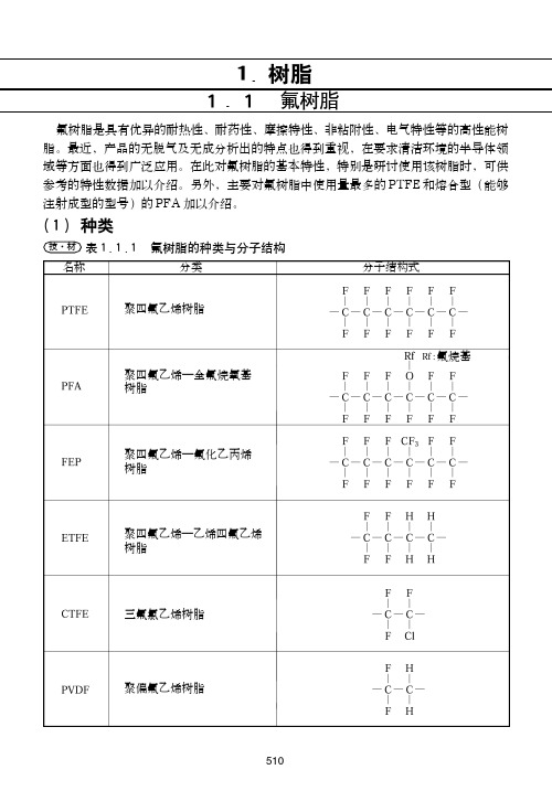
表1.1.1氟树脂的种类与分子结构技·材1.树脂1.1氟树脂氟树脂是具有优异的耐热性、耐药性、摩擦特性、非粘附性、电气特性等的高性能树脂。
最近,产品的无脱气及无成分析出的特点也得到重视,在要求清洁环境的半导体领域等方面也得到广泛应用。
在此对氟树脂的基本特性,特别是研讨使用该树脂时,可供参考的特性数据加以介绍。
另外,主要对氟树脂中使用量最多的PTFE 和熔合型(能够注射成型的型号)的PFA 加以介绍。
(1)种类名称分类分子结构式氟烷基聚四氟乙烯树脂聚四氟乙烯—全氟烷氧基树脂聚四氟乙烯—氟化乙丙烯树脂聚四氟乙烯—乙烯四氟乙烯树脂三氟氯乙烯树脂聚偏氟乙烯树脂氟树脂工程塑料(2)特性一览表表1.1.2氟树脂特性一览表1)技·材△:能够使用 ○:优异◎:非常优异 :比◎更优异物理性机械性热性电气性耐久性及其它特 性单位熔点比重拉伸强度伸展率压缩强度冲击强度(埃左氏)硬度(洛氏)硬度(肖氏)弯曲弹性率拉伸弹性率动摩擦系数热传导率比热线膨胀系数球压温度最高使用温度体积阻抗率绝缘击穿的强度(短时间)耐电弧性吸水率24h 燃烧性3.2m m 厚临界氧气指数直射阳光的影响酸碱溶剂热变形温度(无负载)厚试验法未破坏未破坏未破坏未破坏无无无无无无无介电常数介电正切表1.1.3各种氟树脂的耐化学药品性技·材(3)耐化学药品性(4)PTFE 的特性(a )热性质(甲)热膨胀PTFE显示出了与一般的树脂相同等级的热膨胀系数。
在23℃附近存在特有的转移点,尺寸变化将增大,需加以注意。
表1.1.4PTFE 的线膨胀系数1)技·材名称耐化学药品性对于绝大多数的化学药品有非常稳定的性质,仅会被熔化碱金属和此类溶液以及高温的氟、三氟化氯等侵蚀。
与PTFE 相同与PTFE 相同与PTFE 基本相同但会受浓硝酸侵蚀。
比PTFE 略差。
除会受熔化碱金属、高温的氟、三氟化氯的侵蚀外,在高温下还会受氯气及氨气的一定侵蚀。
塑料检测标准
同科橡胶塑料研究所部分检测标准GB/T1033.1-2008塑料非泡沫塑料密度的测定第1部分:浸渍法、液体比重瓶法和滴定法ASTM D792-08塑料用替代法测密度和相对密度的标准试验方法GB/T 1034-2008塑料吸水性的测定GB/T 606-2003 化学试剂水分测定通用方法卡尔.费休法GB/T1040.1-2006塑料拉伸性能的测定第1部分:一般原则ISO527-1:1993塑料拉伸性能的测定第1部分:一般原则GB/T1040.2-2006塑料拉伸性能的测定第2部分:模塑和挤塑塑料的试验条件ISO527-2-1993塑料拉伸性能的测定第2部分:模压和挤压塑料试验条件GB/T1040.3-2006塑料拉伸性能的测定第3部分:薄膜和薄片的试验条件ISO527-3:1995塑料拉伸性能的测定第3部分:薄膜和薄板材的试验条件ASTM D638-08塑料拉伸性能的标准试验方法GB/T 1041-2008塑料压缩性能的测定ISO 604:2002塑料.压缩性能的测定ASTM D695-08硬质塑料压缩性能的标准试验方法GB/T 8813-2008硬质泡沫塑料压缩试验方法GB/T1043.1-2008塑料简支梁冲击性能的测定第1部分:非仪器化冲击试验ISO179-1:2000塑料简支梁冲击性能的测定第1部分:非仪器化冲击试验ISO179-2:1997塑料——简支梁冲击性能的测定第2部分仪器化冲击试验第一版技术勘误1ASTM D6110-08塑料缺口试样简支梁冲击的标准试验方法GB/T1633-2000热塑性塑料维卡软化温度(VST)的测定ISO 306:2004塑料——热塑性材料——维卡软化温度(VST)的测定ASTM D1525-07测定塑料维卡软化温度的标准试验方法GB/T1634.1-2004塑料负荷变形温度的测定第1部分:通用试验方法GB/T1634.2-2004塑料负荷变形温度的测定第2部分: 塑料、硬橡胶和长纤维增强复合材料GB/T1634.3-2004塑料负荷变形温度的测定第3部分: 高强度热固性层压材料ISO 75-2:2004 塑料.弯曲负载热变形温度的测定.第2部分:塑料和硬橡胶ASTM D648-07塑料弯曲负载在边缘的热变形温度的标准试验方法GB/T 1843-2008塑料悬臂梁冲击强度的测定ISO 180:2000塑料——悬臂梁冲击强度的测定ASTM D 256-06塑料悬臂梁摆锤冲击强度测定的标准试验方法GB/T2406.1-2008塑料用氧指数法测定燃烧行为第1部分:导则ISO 4589-2:1996塑料.通过氧指数测定其燃烧性.第2部分:室温试验GB/T2408-2008塑料燃烧性能的测定水平法和垂直法GB/T8333-2008 硬质泡沫塑料燃烧性能试验方法垂直燃烧法GB/T2411-2008塑料和硬橡胶使用硬度计测定压痕硬度(邵氏硬度) GB/T3682-2000热塑性塑料熔体质量流动速率和熔体体积流动速率的测定ISO 1133: 2005塑料—热塑性塑料熔体质量流动速率和熔体体积流动速率的测定ASTM D1238-04c用挤出塑度计测定热塑性塑料熔体流动速率的标准试验方法GB/T 9341-2008塑料弯曲性能的测定ISO 178:2001塑料—弯曲性能的测定ASTM D790-07增强与非增强塑料及电绝缘材料弯曲性能的标准试验方法GB/T 3398.2-2008塑料硬度测定第2部分:洛氏硬度ISO 2039-2:1987塑料.硬度的测定.第2部分:洛氏硬度ASTM D785-08塑料和电绝缘材料洛氏硬度的标准试验方法GB/T9345.1-2008塑料灰分的测定第1部分:通用方法ISO 3451-1:2008塑料.灰份的测定.第1部分:通用方法GB/T14522-2008机械工业产品用塑料、涂料、橡胶材料人工气候老化试验方法荧光紫外灯GB/T16422.3-1997塑料实验室光源暴露试验方法第3部分:荧光紫外线灯ISO 4892-2:2006塑料.暴露于实验室光源的方法.第2部分:氙弧灯ISO 4892-3:2006塑料.实验室光源暴露法.第3部分:UV荧光灯ASTM D4459-06 室内用要求曝露于氙弧灯的塑料标准实施规程GB/T 18424-2001橡胶和塑料软管氙弧灯曝晒颜色和外观变化的测定ISO 11758:1995 橡胶和塑料软管氙弧灯照射颜色和外观变化的测定GB3398.1-2008塑料硬度测定第1部分:球压痕法GB/T 9647-2003热塑性塑料管材环刚度的测定GB/T 19466.1-2004 塑料差示扫描量热法(DSC)第1部分:通则GB/T 19466.2-2004塑料差示扫描量热法(DSC)第2部分:玻璃化转变温度的测定GB/T 19466.3-2004塑料差示扫描量热法(DSC)第3部分:熔融和结晶温度及热焓的测定GB/T 8808-1988软质复合塑料材料剥离试验方法GB/T11547-2008 塑料耐液体化学试剂性能的测定GB/T 5470-2008 塑料冲击法脆化温度的测定GB/T 7141-2008 塑料热老化试验方法ISO 2577:2007塑料.热固性模塑材料.收缩量的测定GB/T 17037.4-2003 塑料热塑性塑料材料注塑试样的制备第4部分:模塑收缩率的测定ISO 294-4:2001塑料.热塑材料试样的注塑法.第4部分:模塑收缩率的测定JB/T 6542-1993 热固性模塑料收缩率的测定ASTM D6289-08 热固性模塑料模塑收缩率试验方法ISO 11358:1997 塑料.高聚物的热重分析法(TG).一般原理ISO 11358-2:2005 塑料高聚物热量的分析法(TG) 第2部分:激活能的测定GB/T1447-2005玻璃纤维增强塑料拉伸性能试验方法GB/T1040.4-2006塑料拉伸性能的测定第4部分:各向同性和正交各向异性纤维增强复合材料的试验条件ISO 527-4:1997 塑料拉伸性能的测定第4部分:各向同性及各向异性纤维增强塑料复合材料试验条件GB/T 1040.5-2008塑料拉伸性能的测定第5部分:单向纤维增强复合材料的试验条件ISO 527-5:2009 塑料拉伸性能的测定第5部分:单向纤维增强塑料复合材料试验条件DIN EN ISO 527-5-2009 塑料.抗拉性能的测定.第5部分:单向增强纤维塑料复合材料试验条件GB/T 3354-1999定向纤维增强塑料拉伸性能试验方法GB/T 4944-2005玻璃纤维增强塑料层合板间拉伸性能试验方法ISO14129:1997纤维增强塑料复合材料用±45°张力试验法测定平面剪应力/剪应变特性,包括平面剪切模量和剪切强度DIN EN ISO 14129:1998 纤维增强塑料符合材料.用45角度拉伸试验方法测定平面内剪切应力/剪切应变响应关系,包括平面剪切模量和剪切强度GB/T 1452-2005夹层结构平拉强度试验方法GB/T 1448-2005玻璃纤维增强塑料压缩性能试验方法GB/T 1453-2005夹层结构或芯子平压性能试验方法GB/T 1454-2005夹层结构或芯子侧压性能试验方法EN ISO 14126:1999 纤维增强塑料混合物.水平方向压缩能力的测定ISO14126:1999纤维增强塑料复合材料平面方向压缩性的测定GB/T 5258-2008纤维增强塑料面内压缩性能试验方法GB/T1449-2005玻璃纤维增强塑料弯曲性能试验方法GB/T 1456-2005夹层结构弯曲性能试验方法ISO14125:1998纤维增强塑料复合材料弯曲性能的测定GB/T 3356-1999单向纤维增强塑料弯曲试验方法GB/T1451-2005玻璃纤维增强塑料简支梁式冲击韧性试验方法GB/T 1450.1-2005玻璃纤维增强塑料层间剪切强度试验方法GB/T 1450.2-2005玻璃纤维增强塑料冲压式剪切强度试验方法GB/T 1455-2005夹层结构或芯子剪切性能试验方法ASTM D732-02 塑料冲压剪切标准试验方法EN 1465-2009粘合剂.刚性对刚性的连接组件拉伸搭接剪切强度的测定ISO14129:1997纤维增强塑料复合材料用±45°张力试验法测定平面剪应力/剪应变特性,包括平面切变模量和剪切强度GB/T 2577-2005 玻璃纤维增强塑料树脂含量试验方法GB/T 3855-2005碳纤维增强塑料树脂含量试验方法GB/T 2576-2005纤维增强塑料树脂不可溶分含量试验方法GB/T 1462-2005纤维增强塑料吸水性试验方法GB/T22314-2008塑料环氧树脂黏度测定方法GB/T 1463-2005 纤维增强塑料密度和相对密度试验方法GB/T 8924-2005 纤维增强塑料燃烧性能试验方法氧指数GB/T 3857-2005 玻璃纤维增强热固性塑料耐化学介质性能试验方法GB/T 2573-2008 玻璃纤维增强塑料老化性能试验方法GB/T 2567-2008 树脂浇铸体性能试验方法GB /T7193-2008不饱和聚酯树脂试验方法。
塑料的压缩强度标准
塑料的压缩强度标准通常是根据材料类型、制造方法和应用领域的不同而有所不同。
不同的国际和国家标准组织可能会制定适用于不同类型塑料的标准。
以下是一些常见的国际和国家标准组织和他们制定的一些与塑料的压缩强度相关的标准:
1. **ASTM国际标准**:美国材料与试验协会(ASTM)制定了许多与塑料材料性能和测试方法相关的标准。
例如,ASTM D695 - 15标准规定了在室温下测定塑料的压缩强度的方法。
2. **ISO国际标准**:国际标准化组织(ISO)也制定了与塑料材料性能相关的标准。
例如,ISO 604:2002规定了测定塑料的压缩强度的方法。
3. **EN欧洲标准**:欧洲标准化委员会(CEN)制定了适用于欧洲市场的塑料材料标准。
这些标准可能包括与压缩强度有关的测试方法。
4. **GB国家标准**:中国国家标准化管理委员会(SAC)制定了与塑料材料性能和测试方法相关的国家标准。
一些标准可能包括塑料的压缩强度测试。
5. **其他国家和地区标准**:其他国家和地区也可能制定适用于其境内塑料制造和使用的标准。
这些标准可能会与ASTM、ISO或EN等国际标准相一致,也可能存在一些差异。
要查找特定塑料材料的压缩强度标准,您可以参考适用的国际、国家或地区标准组织的官方网站,或者联系相关的材料制造商或实验室,以获取有关测试方法和标准的详细信息。
请注意,在进行任何材料性能测试时,应按照标准规程和适当的测试设备进行测试,以确保测试的准确性和可重复性。
T.金属材料的常用试验标准.

T.金属材料的常用试验标准:GB2280 —87(金属拉伸-旧)GB228-2000 (金属拉伸-新)GB7314-87 (金属压缩)GB/T14452-93 (金属弯曲)GB/T232-1999 (金属弯曲)GB10120-1996 (金属松弛))GB/T4338-1995 (金属高温拉伸)GB5027-85 (金属薄板r 值)GB5028-85 (金属薄板n 值)GB3355-82 (纵横剪切)GB8653-1988 (金属杨氏模量的测定方法)GB3851-83 (硬质合金横向断裂强度的测定)HB5143-96 (金属拉伸)HB5195-96 (金属高温拉伸)HB5280-96 (金属箔材拉伸)HB5177-96 (金属丝材拉伸)HB5145-96 (金属管材拉伸)ASTM E8-99 (美标金属拉伸)ASTM E290-97a (美标金属弯曲)JIS Z2241-1998 (日标金属拉伸)JIS Z2248-1998 (日标金属弯曲)BS 4483-1985 (英标金属拉伸)BS 1639 :1964 (英标金属弯曲)DIN 50125-1991 (德标金属拉伸)DIN 50111-1987 (德标金属弯曲)ISO 6892-1998 (E)(国际标准金属拉伸)ISO 7348-1985 (E)(国际标准金属弯曲)橡胶材料常用试验标准:GB/T528-92 (橡胶拉伸试验)GB/T529-1999 (硫化橡胶或热塑橡胶撕裂强度测定)GB530-81 (硫化橡胶撕裂强度的测定方法)GB1684-85 (硫化橡胶短时间静压缩试验方法)GB9871-88 (硫化橡胶老化性能的测定-拉伸应力松弛试验)GB/T15254-94 (硫化橡胶与金属粘接180 度剥离试验)GB/T1701-2001 (硬质橡胶拉伸强度和拉断伸长率的测定)GB/T2438-2002 (硬质橡胶压碎强度的测定)GB/T1696-2001 (硬质橡胶弯曲强度的测定)GB11211-89 (硫化橡胶与金属粘合强度的测定方法)HG4-852-81 (硫化橡胶与金属粘接扯离强度的测定方法)HG4-853-81 (硫化橡胶与金属粘接剪切强度的测定方法)HG/T2580-94 橡胶拉伸强度和断裂伸长率的测定)GB/T13936-92 (硫化橡胶与金属粘接拉剪强度的测定方法)GB/T1700-2001 (硬质橡胶抗剪强度的测定)GB/T7757-93 (硫化橡胶压缩应力应变性能的测定)GB/T2942-91 (硫化橡胶和织物帘线粘合强度的测定)GB/T7544。
塑料应力测试方法及标准

塑料应力测试方法及标准塑料材料的应力测试在材料科学和工程领域中具有重要意义,其测试方法主要分为两大类:机械性能测试和热性能测试。
下面将详细介绍各种测试方法及其标准。
1.拉伸强度测试拉伸强度是衡量塑料材料在拉伸过程中所能承受的最大负荷。
测试标准采用ASTM D638,样品通常为哑铃状,通过拉伸速度控制试样延伸,记录试样断裂时的最大负荷。
2.弯曲强度测试弯曲强度是衡量塑料材料在承受弯曲负荷时的能力。
测试标准采用ASTM D790,样品通常为矩形条,跨距在两支点之间,记录样品在弯曲断裂时的最大负荷。
3.压缩强度测试压缩强度是衡量塑料材料在承受压缩负荷时的能力。
测试标准采用ASTM D695,样品通常为圆柱形,在压力试验机上以一定的速度施加负荷,记录样品在压缩断裂时的最大负荷。
4.冲击强度测试冲击强度是衡量塑料材料在承受冲击负荷时的能力。
测试标准采用ASTM D256,样品通常为矩形条,通过摆锤冲击样品,记录样品在冲击断裂时的最大能量。
5.热变形温度测试热变形温度是衡量塑料材料在受热时保持原有形状的能力。
测试标准采用ASTM D648,样品通常为矩形条,通过逐渐加热并施加一定负荷,记录样品开始变形的温度。
6.维卡软化点温度测试维卡软化点温度是衡量塑料材料在受热时开始软化的温度。
测试标准采用ASTM D1525,样品通常为小圆柱形,通过逐渐加热并施加一定负荷,记录样品开始变形的温度。
7.邵氏硬度测试邵氏硬度是衡量塑料材料表面硬度的一种方法。
测试标准采用ASTM D2240,样品通常为矩形条或圆形片状,通过在样品表面施加一定负荷,测量样品表面形变的数值来表示硬度。
8.落锤冲击测试落锤冲击测试是评估塑料材料抗冲击能力的方法。
测试标准采用ASTM D3039,样品通常为矩形条或圆形片状,通过让一定质量的重锤从一定高度自由落体冲击样品,观察样品是否破裂或变形。
9.蠕变测试蠕变测试是评估塑料材料在长时间恒定负荷下的变形能力。
塑料拉伸 压缩和弯曲蠕变和蠕变破裂的标准测试方法

一、概述塑料材料的力学性能是其在工程应用中至关重要的一项指标。
其中塑料材料在不同的应力状态下的拉伸、压缩和弯曲性能以及蠕变和蠕变破裂性能是其重要的力学性能参数。
对塑料材料进行标准测试方法的研究和制定对于保证塑料制品的质量和工程应用的可靠性具有重要意义。
二、塑料拉伸测试的标准方法1. ASTM D638-14 标准测试方法,它规定了用于测定拉伸性能的试样形状和尺寸以及测试条件,包括拉伸速度等;2. ISO 527-5 标准方法,该标准规定了用于测定拉伸性能的试样的制备要求和拉伸试验方法;3. GB/T 1040.1-2006 标准方法,这是我国国家标准,规定了塑料材料拉伸试验的一般方法。
三、塑料压缩和弯曲测试的标准方法1. ASTM D695-15 标准测试方法,该标准规定了用于测定塑料材料压缩性能的试样形状和尺寸,以及测试条件;2. ISO 604 标准方法,该标准覆盖了用于测定塑料材料弯曲性能的试样形状和尺寸,以及测试条件;3. GB/T 9341-2008 标准方法,这是我国国家标准,规定了用于测定塑料材料弯曲性能的试样制备和测试方法。
四、塑料蠕变和蠕变破裂测试的标准方法1. ASTM D2990-16 标准测试方法,其中包括了用于测定塑料材料蠕变性能的试样形状和尺寸,以及测试条件;2. ISO 899-1 标准方法,该标准规定了用于测定塑料材料蠕变性能的试样制备和测试方法;3. GB/T 2571-2007 标准方法,这是我国国家标准,规定了用于测定塑料材料蠕变性能的试样形状和尺寸,以及测试条件。
五、总结标准测试方法的制定对于评价塑料材料的力学性能具有重要意义,不仅可以确保塑料制品的质量,还可以保证工程应用的可靠性。
目前,国际上和我国国内都已经针对塑料材料的拉伸、压缩、弯曲、蠕变和蠕变破裂等性能制定了一系列标准测试方法,这些标准方法为塑料材料的研究和应用提供了重要的技术支持。
希望在未来的工程领域中,能够进一步完善和更新这些标准测试方法,为塑料材料的应用和发展提供更加可靠的技术基础。
实验标准
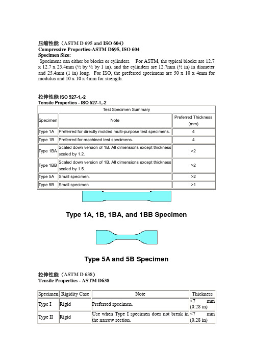
压缩性能(ASTM D 695 and ISO 604)Compressive Properties-ASTM D695, ISO 604Specimen Size:Specimens can either be blocks or cylinders. For ASTM, the typical blocks are 12.7 x 12.7 x 25.4mm (½ by ½ by 1 in). and the cylinders are 12.7mm (½ in) in diameter and 25.4mm (1 in) long. For ISO, the preferred specimens are 50 x 10 x 4mm for modulus and 10 x 10 x 4mm for strength.拉伸性能ISO 527-1,-2Type 1A, 1B, 1BA, and 1BB SpecimenType 5A and 5B Specimen拉伸性能(ASTM D 638)Tensile Properties - ASTM D638Type III Rigid/Nonrigid>7 mm(0.28 in)<14 mm(0.55 in)Type IV Rigid/NonrigidShould be used for comparison betweenmaterials in different rigidity cases. Essentiallythe same as Die C specimen from ASTMD412.<4 mm(0.16 in) Type V RigidUsed when limited material is available orlaboratory space is a concern (forenvironmental testing)<4 mm(0.16 in)。
塑料鞋底耐压缩性能测试考核试卷
考生姓名:__________答题日期:__________得分:__________判卷人:__________
一、单项选择题(本题共20小题,每小题1分,共20分,在每小题给出的四个选项中,只有一项是符合题目要求的)
1.塑料鞋底材料中,以下哪种材料的耐压缩性能最好?()
B.压缩位移
C.压缩强度
D.所有上述参数
15.以下哪些方法可以用来分析塑料鞋底耐压缩性能的测试结果?()
A.数据图表
B.统计分析
C.实验重复
D.观察和描述
16.塑料鞋底耐压缩性能测试中,以下哪些安全措施是必要的?()
A.使用安全眼镜
B.确保试验机周围无障碍物
C.在测试前检查设备是否完好
D.在测试期间保持适当的通风
15.在塑料鞋底耐压缩性能测试中,以下哪个参数表示压缩位移?()
A.压缩应力
B.压缩应变
C.弹性模量
D.位移
16.以下哪种塑料鞋底材料具有较好的耐磨损性能?()
A.聚丙烯
B.聚乙烯
C.聚氯乙烯
D.聚四氟乙烯
17.在塑料鞋底耐压缩性能测试中,以下哪个步骤用于确保测试结果的准确性?()
A.重复测试
B.随机抽样
1.请简述塑料鞋底耐压缩性能测试的目的和意义。(10分)
2.描述塑料鞋底耐压缩性能测试的实验步骤,并说明如何确保测试结果的准确性。(10分)
3.请分析影响塑料鞋底耐压缩性能的主要因素,并提出提高耐压缩性能的方法。(10分)
4.假设你是一名鞋底材料研发工程师,请阐述在你设计新型塑料鞋底材料时,如何平衡耐压缩性能与其他性能(如耐磨性、舒适性等)之间的关系。(10分)
A.成本
- 1、下载文档前请自行甄别文档内容的完整性,平台不提供额外的编辑、内容补充、找答案等附加服务。
- 2、"仅部分预览"的文档,不可在线预览部分如存在完整性等问题,可反馈申请退款(可完整预览的文档不适用该条件!)。
- 3、如文档侵犯您的权益,请联系客服反馈,我们会尽快为您处理(人工客服工作时间:9:00-18:30)。
Designation:D695–02An American National Standard Standard Test Method forCompressive Properties of Rigid Plastics1This standard is issued under thefixed designation D695;the number immediately following the designation indicates the year oforiginal adoption or,in the case of revision,the year of last revision.A number in parentheses indicates the year of last reapproval.Asuperscript epsilon(e)indicates an editorial change since the last revision or reapproval.This standard has been approved for use by agencies of the Department of Defense.1.Scope1.1This test method covers the determination of the me-chanical properties of unreinforced and reinforced rigid plas-tics,including high-modulus composites,when loaded in compression at relatively low uniform rates of straining or loading.Test specimens of standard shape are employed.1.2The values stated in SI units are to be regarded as the standard.The values in parentheses are for information only. N OTE1—For compressive properties of resin-matrix composites rein-forced with oriented continuous,discontinuous,or cross-ply reinforce-ments,tests may be made in accordance with Test Method D3410. 1.3This standard does not purport to address all of the safety concerns,if any,associated with its use.It is the responsibility of the user of this standard to establish appro-priate safety and health practices and determine the applica-bility of regulatory limitations prior to use.A specific precau-tionary statement is given in Note11.N OTE2—This test method is technically equivalent to ISO604.2.Referenced Documents2.1ASTM Standards:D618Practice for Conditioning Plastics for Testing2D638Test Method for Tensile Properties of Plastics2D3410Test Method for Compressive Properties of Poly-mer Matrix Composite Materials with Unsupported Gage Section by Shear Loading3D4000Classification System for Specifying Plastic Mate-rials4D4066Specification for Nylon Injection and Extrusion Materials4E4Practices for Force Verification of Testing Machines5 E83Practice for Verification and Classification of Exten-someters5E691Practice for Conducting an Interlaboratory Study toDetermine the Precision of a Test Method63.Terminology3.1Definitions:3.1.1compressive deformation—the decrease in length pro-duced in the gage length of the test specimen by a compressive load.It is expressed in units of length.3.1.2compressive strain—the ratio of compressive defor-mation to the gage length of the test specimen,that is,the change in length per unit of original length along the longitu-dinal axis.It is expressed as a dimensionless ratio.3.1.3compressive strength—the maximum compressive stress(nominal)carried by a test specimen during a compres-sion test.It may or may not be the compressive stress (nominal)carried by the specimen at the moment of rupture.3.1.4compressive strength at failure(nominal)—the com-pressive stress(nominal)sustained at the moment of failure of the test specimen if shattering occurs.3.1.5compressive stress(nominal)—the compressive load per unit area of minimum original cross section within the gage boundaries,carried by the test specimen at any given moment. It is expressed in force per unit area.3.1.5.1Discussion—The expression of compressive proper-ties in terms of the minimum original cross section is almost universally used.Under some circumstances the compressive properties have been expressed per unit of prevailing cross section.These properties are called“true”compressive prop-erties.3.1.6compressive stress-strain diagram—a diagram in which values of compressive stress are plotted as ordinates against corresponding values of compressive strain as abscis-sas.3.1.7compressive yield point—thefirst point on the stress-strain diagram at which an increase in strain occurs without an increase in stress.3.1.8compressive yield strength—normally the stress at the yield point(see also section3.113.1.11).3.1.9crushing load—the maximum compressive force ap-plied to the specimen,under the conditions of testing,that produces a designated degree of failure.3.1.10modulus of elasticity—the ratio of stress(nominal)to1This test method is under the jurisdiction of ASTM Committee D20on Plasticsand is the direct responsibility of Subcommittee D20.10on Mechanical Properties.Current edition approved April10,2002.Published June2002.Originallypublished as D695–st previous edition D695–96.2Annual Book of ASTM Standards,V ol08.01.3Annual Book of ASTM Standards,V ol15.03.4Annual Book of ASTM Standards,V ol08.02.5Annual Book of ASTM Standards,V ol03.01.6Annual Book of ASTM Standards,V ol14.02.1Copyright©ASTM International,100Barr Harbor Drive,PO Box C700,West Conshohocken,PA19428-2959,United States.corresponding strain below the proportional limit of a material. It is expressed in force per unit area based on the average initial cross-sectional area.3.1.11offset compressive yield strength—the stress at which the stress-strain curve departs from linearity by a specified percent of deformation(offset).3.1.12percent compressive strain—the compressive defor-mation of a test specimen expressed as a percent of the original gage length.3.1.13proportional limit—the greatest stress that a material is capable of sustaining without any deviation from propor-tionality of stress to strain(Hooke’s law).It is expressed in force per unit area.3.1.14slenderness ratio—the ratio of the length of a col-umn of uniform cross section to its least radius of gyration.For specimens of uniform rectangular cross section,the radius of gyration is0.289times the smaller cross-sectional dimension. For specimens of uniform circular cross section,the radius of gyration is0.250times the diameter.4.Significance and Use4.1Compression tests provide information about the com-pressive properties of plastics when employed under conditions approximating those under which the tests are made.For many materials,there may be a specification that requires the use of this test method,but with some procedural modifications that take precedence when adhering to the specification.Therefore, it is advisable to refer to that material specification before using this test method.Table1in Classification D4000lists the ASTM materials standards that currently exist.4.2Compressive properties include modulus of elasticity, yield stress,deformation beyond yield point,and compressive strength(unless the material merelyflattens but does not fracture).Materials possessing a low order of ductility may not exhibit a yield point.In the case of a material that fails in compression by a shattering fracture,the compressive strength has a very definite value.In the case of a material that does not fail in compression by a shattering fracture,the compressive strength is an arbitrary one depending upon the degree of distortion that is regarded as indicating complete failure of the material.Many plastic materials will continue to deform in compression until aflat disk is produced,the compressive stress(nominal)rising steadily in the process,without any well-defined fracture pressive strength can have no real meaning in such cases.4.3Compression tests provide a standard method of obtain-ing data for research and development,quality control,accep-tance or rejection under specifications,and special purposes. The tests cannot be considered significant for engineering design in applications differing widely from the load-time scale of the standard test.Such applications require additional tests such as impact,creep,and fatigue.4.4Before proceeding with this test method,reference should be made to the specification of the material being tested. Any test specimen preparation,conditioning,dimensions,and testing parameters covered in the materials specification shall take precedence over those mentioned in this test method.If there is no material specification,then the default conditions apply.5.Apparatus5.1Testing Machine—Any suitable testing machine capable of control of constant-rate-of-crosshead movement and com-prising essentially the following:5.1.1Drive Mechanism—A drive mechanism for imparting to the cross-head movable member,a uniform,controlled velocity with respect to the base(fixed member),with this velocity to be regulated as specified in Section9.5.1.2Load Indicator—A load-indicating mechanism ca-pable of showing the total compressive load carried by the test specimen.The mechanism shall be essentially free from inertia-lag at the specified rate of testing and shall indicate the load with an accuracy of61%of the maximum indicated value of the test(load).The accuracy of the testing machine shall be verified at least once a year in accordance with Practices E4.5.2Compressometer—A suitable instrument for determin-ing the distance between twofixed points on the test specimen at any time during the test.It is desirable that this instrument automatically record this distance(or any change in it)as a function of the load on the test specimen.The instrument shall be essentially free of inertia-lag at the specified rate of loading and shall conform to the requirements for a Class B-2 extensometer as defined in Practice E83.N OTE3—The requirements for extensometers cited herein apply to compressometers as well.5.3Compression Tool—A compression tool for applying the load to the test specimen.This tool shall be so constructed that loading is axial within1:1000and applied through surfaces that areflat within0.025mm(0.001in.)and parallel to each other in a plane normal to the vertical loading axis.Examples of suitable compression tools are shown in Fig.1and Fig.2. 5.4Supporting Jig—A supporting jig for thin specimens is shown in Fig.3and Fig.4.5.5Micrometers—Suitable micrometers,reading to0.01 mm or0.001in.for measuring the width,thickness,and length of the specimens.6.Test Specimens6.1Unless otherwise specified in the materials specifica-tions,the specimens described in6.2and6.7shall be used. These specimens may be prepared by machining operations from materials in sheet,plate,rod,tube,or similar form,or they may be prepared by compression or injection molding of the material to be tested.All machining operations shall be done carefully so that smooth surfaces result.Great care shall be taken in machining the ends so that smooth,flat parallel surfaces and sharp,clean edges,to within0.025mm(0.001in.) perpendicular to the long axis of the specimen,result.6.2The standard test specimen,except as indicated in 6.3-6.7,shall be in the form of a right cylinder or prism whose length is twice its principal width or diameter.Preferred specimen sizes are12.7by12.7by25.4mm(0.50by0.50by 1in.)(prism),or12.7mm in diameter by25.4mm(cylinder). Where elastic modulus and offset yield-stress data are desired, the test specimen shall be of such dimensions that the slender-ness ratio is in the range from11to16:1.In this case,preferred specimen sizes are12.7by12.7by50.8mm(0.50by0.50by2in.)(prism),or 12.7mm in diameter by 50.8mm (cylinder).6.3For rod material,the test specimen shall have a diameter equal to the diameter of the rod and a sufficient length to allow a specimen slenderness ratio in the range from 11to 16:1.6.4When testing tubes,the test specimen shall have a diameter equal to the diameter of the tube and a length of 25.4mm (1in.)(Note 4).For crushing-load determinations (at right angles to the longitudinal axis),the specimen size shall be the same,with the diameter becoming the height.N OTE 4—This specimen can be used for tubes with a wall thickness of1mm (0.039in.)or over,to inside diameters of 6.4mm (0.25in.)or over,and to outside diameters of 50.8mm (2.0in.)or less.6.5Where it is desired to test conventional high-pressure laminates in the form of sheets,the thickness of which is less than 25.4mm (1in.),a pile-up of sheets 25.4mm square,with a sufficient number of layers to produce a height of at least 25.4mm,may be used.6.6When testing material that may be suspected of anisot-ropy,duplicate sets of test specimens shall be prepared having their long axis respectively parallel with and normal to the suspected direction of anisotropy.6.7Reinforced Plastics,Including High-Strength Compos-ites and High-Strength Composites and Highly Orthotropic Laminates —The following specimens shall be used for rein-forced materials,or for other materials when necessary to comply with the slenderness ratio requirements or to permit attachment of a deformation-measuring device.6.7.1For materials 3.2mm (1⁄8in.)and over in thickness,a specimen shall consist of a prism having a cross section of 12.7mm (1⁄2in.)by the thickness of the material and a length such that the slenderness ratio is in the range from 11to 16:1(Note 5).6.7.2For materials under 3.2mm (1⁄8in.)thick,or where elastic modulus testing is required and the slenderness ratio does not provide for enough length for attachment of a compressometer or similar device,a specimen conforming to that shown in Fig.5shall be used.The supporting jig shown in Fig.3and Fig.4shall be used to support the specimen during testing (Note 6).N OTE 5—If failure for materials in the thickness range of 3.2mm (1⁄8in.)is by delamination rather than by the desirable shear plane fracture,the material may be tested in accordance with 6.7.2.N OTE 6—Round-robin tests have established that relatively satisfactory measurements of modulus of elasticity may be obtained by applying a compressometer to the edges of the jig-supported specimen.6.8When testing syntactic foam,the standard test specimen shall be in the form of a right cylinder 25.4mm (1in.)in diameter by 50.8mm (2in.)in length.7.Conditioning7.1Conditioning —Condition the test specimens at 2362°C (73.463.6°F)and 5065%relative humidity for not less than 40h prior to test in accordance with Procedure AofN OTE 1—Devices similar to the one illustrated have been successfully used in a number of different laboratories.Details of the device developed at the National Institute for Standards and Technology are given in the paper by Aitchinson,C.S.,and Miller,J.A.,“A Subpress for Compressive Tests,”National Advisory Committee for Aeronautics,Technical Note No.912,1943.FIG.1Subpress for CompressionTestsFIG.2CompressionToolFIG.3Support Jig for ThisSpecimenPractice D 618unless otherwise specified by contract or the relevant ASTM material specification.Reference pre-test con-ditioning,to settle disagreements,shall apply tolerances of 61°C (1.8°F)and 62%relative humidity.7.2Test Conditions —Conduct the tests at 2362°C (73.463.6°F)and 5065%relative humidity unless otherwise specified by contract or the relevant ASTM material specifica-tion.Reference testing conditions,to settle disagreements,shall apply tolerances of 61°C (1.8°F)and 62%relative humidity.8.Number of Test Specimens8.1At least five specimens shall be tested for each sample in the case of isotropic materials.8.2Ten specimens,five normal to and five parallel with the principal axis of anisotropy,shall be tested for each sample in the case of anisotropic materials.8.3Specimens that break at some obvious fortuitous flow shall be discarded and retests made,unless such flaws consti-tute a variable,the effect of which it is desired to study.9.Speed of Testing9.1Speed of testing shall be the relative rate of motion of the grips or test fixtures during the test.Rate of motion of the driven grip or fixture when the machine is running idle may be used if it can be shown that the resulting speed of testing is within the limits of variation allowed.9.2The standard speed of testing shall be 1.360.3mm (0.05060.010in.)/min,except as noted in 10.5.4.10.Procedure10.1Measure the width and thickness of the specimen to the nearest 0.01mm (0.001in.)at several points along its length.Calculate and record the minimum value of the cross-sectional area.Measure the length of the specimen and record the value.10.2Place the test specimen between the surfaces of the compression tool,taking care to align the center line of its long axis with the center line of the plunger and to ensure that the ends of the specimen are parallel with the surface of the compression tool.Adjust the crosshead of the testing machine until it just contacts the top of the compression toolplunger.N OTE 1—Cold rolled steel.N OTE 2—Furnished four steel machine screws and nuts,round head,slotted,length 31.75mm (11⁄4in.).N OTE 3—Grind surfaces denoted “Gr.”FIG.4Support Jig,DetailsFIG.5Compression Test Specimen for Materials Less than 3.2mmThickN OTE7—The compression tool may not be necessary for testing of lower modulus(for example,100000to500000psi)material if the loading surfaces are maintained smooth,flat,and parallel to the extent that buckling is not incurred.10.3Place thin specimens in the jig(Fig.3and Fig.4)so that they areflush with the base and centered(Note8).The nuts or screws on the jig shall befinger tight(Note9).Place the assembly in the compression tool as described in5.3.N OTE8—A round-robin test,designed to assess the influence of specimen positioning in the supporting jig(that is,flush versus centered mounting),showed no significant effect on compressive strength due to this variable.However,flush mounting of the specimen with the base of the jig is specified for convenience and ease of mounting.7N OTE9—A round-robin test on the effect of lateral pressure at the supporting jig has established that reproducible data can be obtained with the tightness of the jig controlled as indicated.10.4If only compressive strength or compressive yield strength,or both,are desired,proceed as follows:10.4.1Set the speed control at1.3mm/min(0.050in./min) and start the machine.10.4.2Record the maximum load carried by the specimen during the test(usually this will be the load at the moment of rupture).10.5If stress-strain data are desired,proceed as follows: 10.5.1Attach compressometer.10.5.2Set the speed control at1.3mm/min(0.050in./min) and start the machine.10.5.3Record loads and corresponding compressive strain at appropriate intervals of strain or,if the test machine is equipped with an automatic recording device,record the complete load-deformation curve.10.5.4After the yield point has been reached,it may be desirable to increase the speed from5to6mm/min(0.20to 0.25in./min)and allow the machine to run at this speed until the specimen breaks.This may be done only with relatively ductile materials and on a machine with a weighing system with response rapid enough to produce accurate results. 11.Calculation11.1Compressive Strength—Calculate the compressive strength by dividing the maximum compressive load carried by the specimen during the test by the original minimum cross-sectional area of the specimen.Express the result in megapas-cals or pounds-force per square inch and report to three significantfigures.11.2Compressive Yield Strength—Calculate the compres-sive yield strength by dividing the load carried by the specimen at the yield point by the original minimum cross-sectional area of the specimen.Express the result in megapascals or pounds-force per square inch and report to three significantfigures.11.3Offset Yield Strength—Calculate the offset yield strength by the method referred to in3.1.11.11.4Modulus of Elasticity—Calculate the modulus of elas-ticity by drawing a tangent to the initial linear portion of the load deformation curve,selecting any point on this straight line portion,and dividing the compressive stress represented by this point by the corresponding strain,measure from the point where the extended tangent line intersects the strain-axis. Express the result in gigapascals or pounds-force per square inch and report to three significantfigures(see Annex A1).11.5For each series of tests,calculate to three significant figures the arithmetic mean of all values obtained and report as the“average value”for the particular property in question. 11.6Calculate the standard deviation(estimated)as follows and report to two significantfigures:s5=~(X22nX¯2!/~n21!(1) where:s=estimated standard deviation,X=value of single observation,n=number of observations,andX¯=arithmetic mean of the set of observations.N OTE10—The method for determining the offset compressive yield strength is similar to that described in the Annex of Test Method D638.12.Report12.1Report the following information:12.1.1Complete identification of the material tested,includ-ing type,source,manufacturer’s code number,form,principal dimensions,previous history,etc.,12.1.2Method of preparing test specimens,12.1.3Type of test specimen and dimensions,12.1.4Conditioning procedure used,12.1.5Atmospheric conditions in test room,12.1.6Number of specimens tested,12.1.7Speed of testing,12.1.8Compressive strength,average value,and standard deviation,12.1.9Compressive yield strength and offset yield strength average value,and standard deviation,when of interest, 12.1.10Modulus of elasticity in compression(if required), average value,standard deviation,12.1.11Date of test,and12.1.12Date of test method.13.Precision and Bias813.1Table1and Table2are based on a round-robin test conducted in1987in accordance with Practice E691,involv-ing three materials tested by six laboratories for Test Method D695M.Since the test parameters overlap within tolerances and the test values are normalized,the same data are used for both test methods.For each material,all of the samples were prepared at one source.Each test result was the average offive individual determinations.Each laboratory obtained two test results for each material.N OTE11—Caution:The following explanations of r and R(13.2-13.2.3)are only intended to present a meaningful way of considering the approximate precision of this test method.The data in Table1and Table 2should not be rigorously applied to acceptance or rejection of material, as those data are specific to the round robin and may not be representative7Supporting data are available from ASTM Headquarters.Request RR:D20-1061.8Supporting data are available from ASTM Headquarters,Request RR:D20-1150.of other lots,conditions,materials,or ers of this test method should apply the principles outlined in Practice E 691to generatedata specific to their laboratory and materials or between specific laboratories.The principles of 13.2-13.2.3would then be valid for such data.13.2Concept of r and R —If S (r )and S (R )have been calculated from a large enough body of data,and for test results that were averages from testing five specimens:13.2.1Repeatability,r —Comparing two test results for the same material,obtained by the same operator using the same equipment on the same day.The two test results should be judged not equivalent if they differ by more than the r value for that material.13.2.2Reproducibility,R —Comparing two results for the same material,obtained by different operators using different equipment on different days.The two test results should be judged not equivalent if they differ by more than R value for that material.13.2.3Any judgement in accordance with 13.2.1and 13.2.2would have an approximate 95%(0.95)probability of being correct.13.3There are no recognized standards by which to esti-mate the bias of this test method.14.Keywords14.1compressive properties;compressive strength;modu-lus of elasticity;plasticsANNEX(Mandatory Information)A1.TOE COMPENSATIONA1.1In a typical stress-strain curve (Fig.A1.1)there is a toe region,AC ,that does not represent a property of the material.It is an artifact caused by a takeup of slack,and alignment or seating of the specimen.In order to obtain correct values of such parameters as modulus,strain,and offset yield point,this artifact must be compensated for to give the corrected zero point on the strain or extension axis.A1.2In the case of a material exhibiting a region of Hookean (linear)behavior (Fig.A1.1),a continuation of the linear (CD )region of the curve is constructed through the zero-stress axis.This intersection (B )is the corrected zero-strain point from which all extensions or strains must be measured,including the yield offset (BE ),if applicable.The elastic modulus can be determined by dividing the stress at any point along the line CD (or its extension)by the strain at the same point (measured from Point B ,defined as zero-strain).A1.3In the case of a material that does not exhibit any linear region (Fig.A1.2),the same kind of toe correction of the zero-strain point can be made by constructing a tangent to the maximum slope at the inflection point (H 8).This is extended to intersect the strain axis at Point B 8,the corrected zero-strainTABLE 1Precision,Compressive Strength(Values in Units of Megapascals )Material Average S r A S R B r C R D Acetal100 1.1 2.1 3.1 5.9Polystyrene106 1.4 3.5 3.99.8Linen-filled phenolic1583.77.510.421.0AS r is the within-laboratory standard deviation for the indicated material.It is obtained by pooling the within-laboratory standard deviations of the test results from all of the participating laboratories:S r =[[(S 1)2+(S 2)2+...+(S n )2]/n ]1/2.BS R is the between-laboratories reproducibility,expressed as a standard deviation,for the indicated material.Cr is the within-laboratory repeatability limit,r =2.83S r .DR is the between-laboratory reproducibility limit,R =2.83S R .TABLE 2Precision,Compressive Modulus(Values in Units of Megapascals )Material Average S r A S R B r C R D Acetal3.280.140.250.390.70Polystyrene3.880.070.740.20 2.07Linen-filled phenolic6.820.230.900.642.52AS r is the within-laboratory standard deviation for the indicated material.It is obtained by pooling the within-laboratory standard deviations of the test results from all of the participating laboratories:S r =[[(S 1)2+(S 2)2+...+(S n )2]/n ]1/2.BS R is the between-laboratories reproducibility,expressed as a standard deviation,for the indicated material.Cr is the within-laboratory repeatability limit,r =2.83S r .DR is the between-laboratory reproducibility limit,R =2.83S R.N OTE 1—Some chart recorders plot the mirror image of this graph.FIG.A1.1Material with HookeanRegioning Point B 8as zero strain,the stress at any point (G 8)on the curve can be divided by the strain at that point to obtaina secant modulus (slope of line B 8G 8).For those materials with no linear region,any attempt to use the tangent through the inflection point as a basis for determination of an offset yield point may result in unacceptable error.ASTM International takes no position respecting the validity of any patent rights asserted in connection with any item mentioned in this ers of this standard are expressly advised that determination of the validity of any such patent rights,and the risk of infringement of such rights,are entirely their own responsibility.This standard is subject to revision at any time by the responsible technical committee and must be reviewed every five years and if not revised,either reapproved or withdrawn.Your comments are invited either for revision of this standard or for additional standards and should be addressed to ASTM International Headquarters.Your comments will receive careful consideration at a meeting of the responsible technical committee,which you may attend.If you feel that your comments have not received a fair hearing you should make your views known to the ASTM Committee on Standards,at the address shown below.This standard is copyrighted by ASTM International,100Barr Harbor Drive,PO Box C700,West Conshohocken,PA 19428-2959,United States.Individual reprints (single or multiple copies)of this standard may be obtained by contacting ASTM at the above address or at 610-832-9585(phone),610-832-9555(fax),or service@ (e-mail);or through the ASTM website().N OTE 1—Some chart recorders plot the mirror image of this graph.FIG.A1.2Material with No HookeanRegion。