SKF变桨润滑系统使用维护说明书
SKF 单线齿轮泵(带泄压阀) - SKF 单线集中润滑系统 用户手册说明书

关于产品使用的重要信息SKF的所有产品都只能用于本手册和说明书中指定的用途。
如果产品附有操作说明,请务必认真阅读并遵守。
并非所有润滑剂都适用于集中润滑系统。
对客户提供的润滑剂,SKF提供检验服务以确定其是否能用于集中润滑系统。
SKF润滑系统或其部件不可用于气体、液化气、加压溶解气体或者最大允许温度下蒸汽压力超过正常大气压力( mbar) .bar以上的液体。
任何危险物若用于填充SKF集中润滑系统和部件或通过SKF润滑系统输出及/或分配,特别是欧盟令EC / /EEC第2条第2部分中所列的危险物,都必须咨询SKF并获得SKF的书面批准。
适用于SKF MonoFlex单线润滑系统的带泄压阀的单线齿轮泵本手册中产品的CAD模型可从以下网址获得:一般信息SKF MonoFlex齿轮泵每次行程的排量有限,这会限制出油量和系统扩展。
这些泵均配备活塞分配器运行所需的泄压设备。
当泵活塞回到正常位置时,还需要通过泄压阀来为主管路泄压。
系统规划时必须考虑系统的润滑需求量。
为了确保所需压力的建立,柱塞泵的排量应至少为润滑需求量的 . 倍。
当规划流体润滑脂系统时,在确定润滑需求量时必须将润滑脂的压缩率(约1%)考虑在内。
润滑需求量包含:系统分配器测得的总量该值的+ %(安全余量)主管路+ cm /m(扩展损失)使用流体润滑脂时的压缩率损失SKF专家可以为您提供更多信息调试如需调试产品,在油箱中填入润滑剂并且以 - 秒间隔启动泵,直至所有润滑点上都有润滑剂排出。
通过以下方式进行排气操作:• 打开主管路的两端,直至从两端排出无气泡的润滑油或流体润滑脂。
• 在连接润滑点之前,特别是针对一些小排量的出口管路,一定要先预填充长的润滑管路。
维护检查液位并及时填充油箱。
根据制造商所提供的信息使用润滑剂。
重新填充润滑油时,使用网式过滤器。
油泵长时间使用后,检查所有管路连接是否存在泄漏并且启动柱塞泵以检查所有润滑点上是否都有润滑剂排出。
变桨系统.操作和维护手册.英文

Operating and maintenance manualCustomer:MingyangWindpower Technology Co.Ltd.Daling Precinct Zhongshan TorcPRC GuangdongManufacturer:SSB-Antriebstechnik GmbH&Co.KGNeuenkirchener Str.13D-48499SalzbergenGermanyOrder No.:2061401620614151Machine:Pitch-System for1.5MW wind energyturbineYear of manufacture:2007Index Index (2)1Safety-General information (4)1.1Terminology Definition (5)1.1.1Qualified personnel (5)1.2Transport and storage (7)1.2.1Transport regulations (7)1.2.2Storage of SSB Pitch Systems (8)2Pitch system layout (9)2.1Main pitch ctrl.cabinet (10)2.2Axis cabinets (11)2.3Battery cabinets (11)2.4Electric pitch motors (12)2.5Pre-installed cables (12)3Mechanical dimension drawings (13)3.1Main pitch control cabinet (13)3.2Axis cabinet (14)3.3Battery cabinet (15)3.4Pinion encoder blade bearing (16)4Commissioning (17)4.1Installation of the components (17)4.2Mounting the switch cabinets (17)4.3Installation of the pitch motor (18)4.4Connecting the cables (18)5Manual Operation (19)5.1General information motion controller GEL8230Y001 (19)5.2Characteristic motion controller (20)5.2.1The key pad (21)5.2.2The display (22)5.2.3Menu structure (23)5.2.2.1Main window(Axis) (24)5.2.2.2Main window(I/O) (26)5.2.2.3Main menu (27)5.2.2.4Device information (27)5.2.2.5Stored failures (28)5.3Homing routine axis/blade (29)6Maintenance (30)General (30)6.1Regular maintenance (31)6.1.1Switch cabinets general (31)6.2Recommendation for preventive maintenance (31)6.2.1Disassembling of the battery cases (33)6.3Disassembly of defective devices (34)6.3.1Exchange of the DGNR speed controller (34)6.3.2Exchange of L&B motion controller (35)6.3.2.1Read current parameter set of motion controller (35)6.3.2.2Disassembly/assembly motion controller (38)6.3.2.3Write parameter to motion controller (40)6.3.3Exchange of damaged cables (41)6.4Recommended spare parts (42)6.4.1Axis cabinet (42)6.4.2Main pitch control cabinet (44)6.4.3Battery cabinet (46)Symbols usedWarning A warning contains information which is important for the prevention of dangers.Caution A section marked with"Caution“contains information which is important for the prevention of damage to the system or to accessories.Note A note contains information about the correct operation of the product.1Safety -General informationFor electrical equipment for use in electrical power installations.This information sheet,together with the warning notices,are a component part of the product-specific operating instructions and must be strictly observed for reasons ofsafety.DANGERThese electric machines or devices are equipmentfor use in industrial power installations.During operation thisequipment has concealed,dangerous,live bare-metal parts,and possibly also moving or rotating parts.They could therefore,e.g.in case of impermissible removal of the required covers,improper use,incorrect operation or insufficient maintenance,cause extremely serious injuries or damage.The person responsible for system safety must therefore ensure that:•Only qualified persons are entrusted with working on the machines or devices •These persons must,among other things,always have the operating instructions and other documents of the product documentation included with the system at their disposal at all times and must be obligated to consistently observe these documents •Work on the machines or devices,or nearby is prohibited for unqualified persons.Always note the following safety requirements andrecommendations before commissioning1.1Terminology Definition1.1.1Qualified personnelQualified persons are,due to their training,experience and instruction,as well as their knowledge of the pertinent standards,regulations,accident prevention regulations and operating conditions,have been authorized by the person responsible for system safety to carry out the respectively required activities,and can recognize and avoid possible dangers in the process(for definitions for specially-trained personnel,also see DIN VDE0105or IEC 364).In addition,knowledge of first-aid measures and the local rescue equipment is also required. For work on power installations,the prohibition of the use of unqualified persons is governed, for example,in DIN VDE0105or IEC364.WarningIt is assumed that the basic planning work for the system and all transport,assembly, installation,commissioning,maintenance and repair work will be carried out by qualified personnel and/or checked by responsible specially trained personnel.In the process,particular attention must be paid to the following:•The technical data and information on the permissible use(installation,connection, environmental and operating conditions),which are included in the catalog,the order documents,•The operating instructions,the rating plate information and the other product documentation•The general installation and safety regulations•The local,system-specific regulations and requirements•The appropriate use of tools,lifting and transport equipment•The use of personal safety equipment•Assembly conditions for devices which are delivered in accordance with IPOO (without covers)if necessary:During operation the required touch guards must beinstalled or a dangerous approach must be prevented.For clarity reasons,the operating instructions cannot contain all detailed information on possible design variants,and in particular cannot take every imaginable installation, operation or maintenance case into account.In accordance with this,the operating instructions mainly contain only those references which are required for qualified personnel (see above)in the case of appropriate use of the machines or devices in industrial application areas.If in special cases the requirements are more demanding when the machines or devices are intended for use in non-industrial areas(e.g.touch guards against children's fingers etc.),these conditions must be ensured during installation with additional protective measures on the system.In case of uncertainty here,in particular in the case of a lack of product-specific detailed information,the required clarifications must be obtained via the responsible SSB agency. Please always specify the machine or device model and serial number for this purpose.It is recommended that,for planning,assembly,commissioning and service tasks,the support and services of the responsible SSB agency be called upon.NoteTo prevent malfunctions,it is necessary to have the specified maintenance,inspection and revision measures carried out regularly by qualified personnel(see above).Changes compared to normal operation(increased power consumption,temperatures or vibrations,unusual noises or odors,actuation of the monitoring equipment etc.)indicate that operation is impaired.To prevent malfunctions which could cause direct or indirect serious injuries or damage,the responsible maintenance personnel must be informed immediately.IN CASE OF DOUBT,SWITCH OFF THE RELEVANT EQUIPMENT IMMEDIATELY!NoteIt is pointed out here that the content of the operating instructions and product documentation is not part of a previous or existing agreement,commitment or legal relationship,nor is it intended to change these in any way.All obligations for SSB result from the respective purchase contract,which also contains the complete and solely valid warranty conditions. These contractual warranty provisions shall be neither expanded nor restricted by the remarks of these instructions and documentation.NoteThe illustrations and pictures used in these instructions are for demonstration purposes and make no claim for reality.If the reader notices differences between the illustration or the picture and the version supplied(in relation to the individual components),an SSB agency should immediately be informed of this,in order to obtain clarification.If operating instructions for individual components are enclosed,they are always to be included as a supplement to the operating instructions at issue.The contents of the operating instructions for the relevant components are neither expanded nor replaced by the“Operating instructions for SSB Pitch Systems”.1.2Transport and storageCautionLifting tools has to be designed for the weight of the machine!In possible assembling or dismantling be careful of rope guide!A switch cabinet,which is not directly put into operation, has to be stored in a dry and vibration-free room.CautionAt housings of electrical devices temperatures up to100°C can occur depending upon load. Contact can cause burns and must be prevented.Also no temperature-sensitive components,e.g.normal cable or electronically parts,should lie close or has to be fastened at the housings.1.2.1Transport regulationsGeneralThis regulation describes the handling for the components manufactured by SSB(switch cabinets and electric motors)for the pitch system:The regulation is to be considered with each unloading and transportation procedure.The carrier is responsible to adhere the requirements of SSB and has to fulfill the legal regulation concerning the transportation lock and the transport insurance.Attention should be paid to:•Using a fork-lift truck the load has to be secured against overbalancing and slipping down from the pallet!•Transporting several switch cabinets on a pallet these are to be secured against slipping,because otherwise a damage of the housing can occurNoteStrong vibrations and hard impacts are to be avoided during transport as well as when lifting and setting down!1.2.2Storage of SSB Pitch SystemsGeneralThis regulation describes the correct storage of the components for the pitch system, manufactured by SSB:The storage contains:•the keeping of the SSB components up to the intended installation of the products into a wind energy plant•the keeping of the inserted components in a plant component up to the evacuation of the component to the building site.For the handling the transportation regulation is to be considered.The following items have to be considered:•The components that are not fitted must be stored in a closed hall•The hall temperature is to be maintained in the range of0°C to+40°C•During storage the relative humidity should be between0%and55%•In the case of temperatures lower than0°C care must be taken to ensure that the heating systems are in good working order so as to achieve an internal cabinet temperature of>0°C•Built-in battery packs are to be protected against discharging by regular trickle charging•During storage the components are to be protected against high humidity and water condensation inside the housing by suitable drying agents•Battery cabinets and pitch motors are not stackable•A maximum of up to3converter cabinets or3control cabinets can be stacked.When doing so,ensure that the external converter box heat sink is not damaged during storage•For protected transport,housing openings must be closed by plugs or adhesive tape and must also remain closed to prevent the ingress of foreign bodies •All housings must always remain closed during storage•The temporary corrosion protection of the unpainted fixing flange in pitch motors must be renewed at regular intervals.2Pitch system layoutThe pitch-system is placed inside the hub of the wind power plant.The scope of supply includes one main pitch ctrl.cabinet,three axis cabinets,three battery cabinets,three direct current electric motor,the required cable connections and the operating manuals.The pitch control system and speed control work together to maintain the rotor at constant power output.Wind gusts cause the rotor to accelerate,but subsequent adjustment of blade pitch smoothly reduces the speed once again.This leads to a significant reduction of the loads on the turbine while at the same time the power is supplied to the grid with a high level of compatibility.In order to maintain blade pitch in the event of grid loss or failures in the pitch power supply or control units,each rotor blade has its own battery back-up that rotates with the blade.In addition to controlling power output,the pitch mechanism serves as the primary safety/ brake system.Each blades pitch mechanism operates independently of the others.Thus in the event of a storm each blade can be moved to a safe position(feather position)to restore the rotor from abnormal situations to safe rotational speeds.Fig.2.1:plot of the pitch system layout2.1Main pitch ctrl.cabinetThe main pitch ctrl.cabinet is the interface between the axis cabinets in the hub and the top box,located in the machine house.The connection between the main pitch ctrl.cabinet and the top box is realized by slip ring. Via this slip ring the main pitch ctrl.cabinet is supplied with power and control signals from the top box.Additionally a Profibus-DP connection for the data exchange between the system management computer and the pitch controller is performed via slip ring.The positioning controller is mounted in the main pitch ctrl.cabinet and controls the positioning of the blades.In addition,the charging process of the back-up system(batteries) in the three battery cabinets is controlled by a central charging unit fitted in the main pitch ctrl.cabinet.Fig.2.2:Main pitch ctrl.cabinet2.2Axis cabinetsThere are three axis cabinets in the pitch system.One axis cabinet is allocated to each blade.The converter operates in4-quadrant mode to control the speed of the corresponding pitch motor.Fig.2.3:Axis cabinet2.3Battery cabinetsLike the axis cabinet,one battery cabinet is allocated to each axis.For the case of a power failure or a reset of the EFC-signal(Emergency Feather Control-signal)each blade will be separately moved to the feather position(limit switch).Fig.2.4:Battery cabinet2.4Electric pitch motorsThe electric pitch motors are direct current machines.Fig.2.5:Electric pitch motorDetailed information concerning the motor(technical data,maintenance etc.)is contained in the appropriate document“Operating instructions for SSB DC Motors Model:GHTIF-07200403.81”2.5Pre-installed cablesThe connection between the main pitch ctrl.cabinet and the top box is realized by slip ring. Via this slip ring the main pitch ctrl.cabinet is supplied with power and control signals from the top box.Additionally a Profibus-DP connection for the data exchange between the system management computer and the pitch controller is performed via slip ring.The connection between the main pitch ctrl.cabinet,the axis cabinet,the battery cabinets and the electric pitch motors is made by pre-installed cables.The delivered cables are coded to prevent an interchange between cables and cabinets.3Mechanical dimension drawings3.1Main pitch control cabinetFig.3.1:Dimension drawing main ctrl.cabinet3.2Axis cabinetFig.3.2:Dimension drawing axis cabinet3.3Battery cabinetFig.3.3:Dimension drawing battery cabinet3.4Pinion encoder blade bearingFig.3.4:Dimension drawing pinion encoder blade bearing4Commissioning4.1Installation of the componentsNoteThe installation of the components and the connecting cables should only be carried out by qualified personnel.WarningThe installation and the cable connection are only to be carried out if all power supplies are disconnected or switched off.The pitch system is to be disconnected from power supply until all components are correctly installed and connected to each other.The batteries for the emergency power supply are already installed.For this reason,the battery maintenance switch must be switched to“off”and only switched to“on”after all connections are made. Caution is needed if the battery cabinet is open and the batteries are interconnected,since there is a voltage of216VDC between positive and negative terminals.WarningThe installation of the pitch system must be carried out with great care.There is a risk of injury or death related to the great dead weight of the components as well as from pointed and sharp edges.Lifting and transporting must be carried out with suitable lifting and transporting equipment(see also Chapter1.2).4.2Mounting the switch cabinetsFig.4.1:Holding rail for the cabinetsFor installing the cabinets inside the hub,the switch cabinets have retaining brackets to which they can be attached with screws or bolts in frames designed for the purpose.When doing so,a firm fit must be ensured.The fastenings can become loose through vibrations in the hub during operation of the wind energy plant,so the screws or bolts must be secured against becoming loose independently.A dynamic suspension is recommended,to protect the cabinets against damage caused by the vibrations.4.3Installation of the pitch motorFig.4.2:Pitch motor4.4Connecting the cablesCautionDo not remove the coding of the plug pare the coding of the plugs with the coding on the cabinets.The inscriptions have to correspond.If the coding at the plug and cabinet is equal,but the inscriptions are different,please contact SSB.Mixing up connections can cause malfunctions in the pitch system and a damage of the plant.Fig.4.3:Connectors at the axis cabinet and the battery cabinetIf all components (cabinets and motors)are installed in the hub,the pre-wired cables can be connected.The plug system is marked and secured by coding pins.5Manual OperationWarningManually movement of the blades can present a risk for personnel and the wind energy plant if not carried out correctly.All essential safety precautions must be taken before a manual operation of the pitch system is undertaken.For this purpose,the appropriate operating instructions are to be consulted and the plant manufacturer’s safety measures are to be noted.WarningOnly one blade should be moved out of the parking position.Consequently,before moving a second blade,it must be ensured that the first blade is in parking position again.5.1General information motion controller GEL8230Y001The Motion Controller is intended exclusively for the control of rotor blade drives in a wind power plant.The three axes are equipped with a redundant encoder system.Encoder A:located at the motor shaftEncoder B:located at the blade bearingIn case of an invalid encoder signal it is possible to select the second encoder set.Control and nominal value preset are carried out by means of an attached field bus module (PROFIBUS-DP)using the specific communication protocol"LB2".The controller measures the motor currents of the three axes via current transducer connected to analog current inputs and three temperatures via analog PT100inputs,and provides averaged values.The values can be accessed via the LB2protocol(8bits)or converted and displayed as motor current in Ampere or as temperature in degrees Celsius respectively.A brief overview of the method of functioning and the operation of the controller is given here. The operator interface and the menu guidance are only for display and do not equate strictly to the supplied version in terms of the controller layout and software.NoteFor general information,safety instructions etc.or a detailed description of the controller, consult the supplied manual.5.2Characteristic motion controllerThe following sketch shows the principle of functioning of the control:Fig.5.1:Operating principle of the controllerFig.5.2:Principle axis controlGeneral information:Information in square brackets refers to the main system parameters for the corresponding blocksFor the actual value inputs/axes/nominal value outputs nos.2…6the same contents apply in principle as for no.1;differences occur with several factory settings and adjustable characteristicsFunction elements with grey background are,by default(from the factory),de-activated.5.2.1The key padFig.5.3:Keyboard1.Function keys(assignment dependent on the current window)2.Numerical keys(value input)3.Menu keys(assignment dependent on the current window,line orientated)4.Delete value input5.Cancel input/function;return to next higher menu level6.Confirm input,select/call marked entry(doubly available)7.Select keys(select characteristic of a system parameter)8.Scroll keys(move window within the displayable list by one line upwards/downwards)5.2.2The displayFig.5.4:Main window1.Number of the currently shown window with total number of windows(e.g.01/03means the first of three possible display2.Designation of the menu or function window3.Function of the menu key‘M1’;with the other menu keys the list entries shown on theleft can be activated in some windows(‘M2’→1st list entry etc.)4.Each list entry is assigned a definite number;when entering a number a searchfunction will be started,which let you go directly to an entry which is currently not visible,or the entry will be activated if it is already shown in the window5.Function of the keys‘F1 (5)(here I/0→‘F1’:display of the input/output states;'UP'→’F4’:scroll1window upwards;'DOWN'→‘F5’:scroll1window downwards)6.List entries The blinking cursor marks the entry which will be selected i.e.activatedwith the confirmation(Enter)keys(see previous section,item6);this is also possible by means of the menu keys M2..M4.7."Scroll bar":Information(qualitative)about the position of the current window(*)within the displayable list(|)Further explanations about the various windows you will found in the following descriptions of the menus.5.2.3Menu structureFor operating and observing of the motion controller various hierarchically classified display windows and configuration menus are available.The following diagram gives an overview of the menu structure.Detailed information for each window/screen is given in the corresponding reference manual of the motion controller.Fig.5.1:Menu structureAfter the device is switched on,the start screen(main window axis)with the angle positions of the axis(blades)will be displayed.The second main window contents an overview according to the status of the analog and digital inputs and the digital outputs of the motion controller(main window I/O)5.2.2.1Main window(Axis)Fig.5.6:Main window with examplePossibilities:1.Browse with and2.Display operating data for marked axis with Enter or e.g.M3(in the window asdisplayed above)for blade2(axis2/4).Fig.5.7:Operating data(Blade2)Explanations of the display:•Velocity(a/n)=actual and nominal speed•DeltaS=control deviation=difference between the calculated nominal value from the feedback control and the actual value•Voltage=control voltage on the analog output(here for Blade2at terminal block A2)•The drive can be operated manually(jog)or calibrated by means of certain function keys if the corresponding blade parameters have been correctlyconfigured(see Reference Manual of motion controller)F1:Fast jog in backward directionF2:Slow jog in backward directionF3:Calibration(see below)F4:Fast jog in forward directionF5:Slow jog in forward directionM1:Return to the MAIN WINDOW(AXES)3.Call information about the inputs and outputs of the Motion Controller:Change to theWINDOW(I/O)by means of F1;see next section4.Call device information or configure system parameters:Change to the MAIN MENUby means of M1Calibration(see also chapter5.3Homing routine axis/blade)Fig.5.8:Calibration(blade2)With the key F3an actual value correction can be activated for a specific blade(encoder group A and B).The value is to be defined at the blade parameters for the concerning axis (see Reference Manual motion controller).Condition:high level at terminal E1.2("/Stop")).5.2.2.2Main window(I/O)Fig.5.9:Main window(I/O)1.Digital inputs0…7on terminal block I22.Logic states of the8inputs in bit form,LSB(right)state of I2.0;1=High approx.24V3.Logic states in hexadecimal formatPossibilities:1.Browse with and2.Display actual values of axes:Change to MAIN WINDOW(AXES)with F1;3.Call device information or configure system parameters:Change to MAIN MENU withM1;see following section5.2.2.3Main menuMenu key M1activation in one of the two main windows:Fig.5.10:Main menuPossibilities:1.Browse with and2.Activate marked menu point with“Enter”and process the next sub-point(seefollowing sections);one of the menu keys M2...M4can also be used for activating3.Change to the MAIN WINDOW(AXES)or MAIN WINDOW(I/O)with F1,M1or ESC;5.2.2.4Device informationThis window informs about the hardware and software versions of the MotionControllers and about the cumulated runtime of the device as shown as an example:Fig.5.10:Device information5.2.2.5Stored failuresThis window displays a list with up to20failures occurred(most recent on top).Principle of memory management is a ring buffer.Fig.5.11:Fault memory("1.05"->axle1,fault code5)The following failures will be recognized:•DeltaS>DeltaS max. Drag error exceeds its maximum value when moving in forward direction(see blade parameters in the reference manual motioncontroller)•DeltaS<DeltaS min. Drag error exceeds its maximum value when moving in the reverse direction•General data transmission failure(stop bit,parity,overwriting or checksum error) and Error in the LB2protocol(see reference manual motion controller)Fig.5.13:Blade-specific window(in this case blade2)By selecting M1you return again to the main menu.(See also Chapter4.1.4)5.3Homing routine axis /bladeWarningOnly one blade should be moved out of the parking position.Consequently,before moving a second blade,it must be ensured that the first blade is in parking position again.The axis to be referenced must first be directly selected in the main window by use of the keys M2-axis1,M3-axis2and M4-axis3.When an axle is selected the following windowopens:Fig.5.14:Blade 2operating dataThe blade to be referenced must now be moved manually to the mechanical zero point of the blade.When this is done,in order to exclude a counting range overflow,the sensor must be set to the counting range mean value by operating the yellow pushbutton.The button is located at the rear of the sensor under a screw cap.Fig.5.15: Sensor pushbuttonThe referencing of the blade can now be started with the F3key.After “Carrying out the calibration”has been confirmed with F1,the current angle value is automatically accepted as the zero point and stored in axis parameter 53.The displayed actual angle value must now be 0°.The referencing is now completed.Return to the main window using M1.6MaintenanceGeneralBecause of the varied operating conditions in which the plant operates(depending on the climatic environment and the load of the wind energy plant),only general recommendations concerning the required maintenance intervals can be given.Regular and careful inspection is required as well as maintenance in order to prevent malfunctions and to detect and remedy faults as they occur,before serious damage happens.In these operating instructions,as regards the maintenance interval,there is only a recommendation which has no effect on contractually specified agreements(especially in relation to the warranty).Before starting any work on the pitch system,especially before opening the covers of live parts,you must ensure that the components and the plant are disconnected in accordance with regulations.In addition to the main circuits also look out for possible boosting or auxiliary circuits,especially standstill heating systems!Here the"5Safety Rules"are(e.g.as per DIN VDE0105):•isolate•secure against restarting•establish isolation from supply•grounding and short-circuiting(for voltages above1000V)•safeguard or cover adjacent live parts.NoteThe supplied operating instructions for the components in question are always applicable for the maintenance intervals and the replacement of components.Always quote the plant number when returning faulty components to SSB.Warning/CautionBecause of the heavy dead weight of a cover or components(such as battery container, pitch motor,transformer,etc.)they must always be removed with great caution,so that they are not damaged during removal,do not damage other components or cause injuries.。
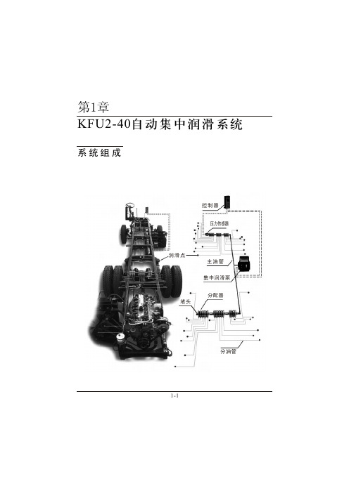
三浪集中润滑KFU操作维护手册
1-10
三、分配器 该分配器为定量卸压式,当油泵工作时分配器储存油脂,当 油泵停止工作,系统主管路卸压后分配器才排出定量的油脂。定 量接头决定分配器每个出口每次的排油量,其有三种类型,分别 打 印 有 10、 20、 40, 分 别 表 示 排 油 量 为 0.1ml/次 、 0.2ml/次 、 0.4ml/次。
1-6
b、工作模式2:只接上PS2(远端)润滑工作时间为PS2闭合 后延时30秒。如在开始工作后105秒PS2仍未闭合,判系统异常, 此种模式的型号为SL-ECU※2,可替代DKQ控制器。
c、工作模式3:同时接上PS1和PS2,系统正常情况下工作时 间 为 PS2闭 合 后 延 时 30秒 , 如 系 统 异 常 , 控 制 器 能 根 据 PS1和 PS2的闭合情况显示相应的故障信息。这种模式多用在要求较高 的 系 统 中 , 一 般 情 况 下 PS1闭 合 与 否 可 检 测 油 箱 是 否 缺 油 , 如 PS1正 常 说 明 油 箱 有 油 ; 但 PS2不 能 闭 合 , 则 说 明 系 统 管 路 有 故 障,此模式的型号为SL-ECU※3。
立刻开始。
SANLANG DKQ-10程序控制器
调试 按钮
故电正工 障源常作
故障 消除
宁波市三浪润滑元件有限公司
注 意: 1、由于控制器具有记忆功能,此次计时是在上次的基础上
累加。 2、无时间显示的控制器在停驶24小时以上,车辆启动后应
先按调试按钮键进行120秒强制润滑。
1-15
■ 当计时计到设定间歇时间(10小时或20小时),工作灯(绿 灯)亮并向油泵发出指令使其工作。
SANLANG DKQ-10程序控制器
调试 按钮
故电正工 障源常作
BEKA变桨润滑系统使用维护说明书

46-48
使用维护手册
安全信息
这本操作指南包含了所有设备安装和操作所需的信息,它有助于操作者熟悉设备和它的相关功能, 以便进行安全、合理、经济的操作。 阅读这本操作指南可帮助您免于设备有可能出现的危险、损坏和故障,增加设备的可靠性和使用寿 命,根据国家关于工作安全、事故预防和环境保护相关的法规来使用操作指南。 操作手册需要一直放在操作台附近,对设备进行操作的人要被告知操作手册内容,尤其是其中的安 全指南,设备的操作者要对员工负责。
泵的部件: 图3:
油箱4l
防过油保护 注油接头
安全阀
泵单元
集成控制器
接线盒
使用维护手册 (2)FKGGM-EP 油脂集中润滑泵FKGGM-EP是一种电力驱动的油脂泵,它是专门为风力发电机组而设计的。 泵自带一个集成控制器和一个油位控制器。
泵的部件: 图4:
油箱8l
注油接头 安全阀
集成控制器
泵单元
接线盒
员工资格认证和培训
用于设备的安装、启动、操作和保养的员工需具备相关的资格证明,设备的操作员必须要明确 所有员工的技术能力和责任并且要对员工进行监督。不具备资格的员工要经过培训和指导。设 备操作员有责任明确相关员工的资质和信息。
使用维护手册
用户安全指南
如果设备变热、变冷或者部件发生移动有可能发生危险时,操作者要确保自己远离 设备接触,这种保护措施不能被忽视。 在注油的情况下,如果发生危险原料泄漏,这些危险原料要被合理的收集和安置以 避免出现人员伤害和环境破坏。 要遵守法律规章 排除各种因电而产生的危险。
图11:
进油口 首块(不带柱塞)
出油口 中块
末块
接近开关
使用维护手册
图12:
递进式分配器由独立的分配器块组成,它们 是首块IE(不带柱塞)、中间块ME和末块EE, 它们是通过螺栓(六角沉头螺钉)和锁紧垫圈 装配起来的。各分配器块之间采用了O形密封 圈。
SKF BlueSonic BWMS操作、维护和安全手册说明书

Coast Guard Approval Number: 162.060/41/0Expires: 14 April 2026BALLAST WATER MANAGEMENT SYSTEMFiltration/Ultraviolet/UltrasoundSKF Marine GmbHHermann-Blohm-Str. 520457Hamburg GERMANYName of BWMS: SKF BlueSonic BWMSCapacities: 100-1,500 m3/hThis is to certify that the above listed BWMS, with the listed treatment capacities, has been satisfactorily examined and tested by Independent Lab DNV in accordance with the requirements contained in 46 CFR 162.060. The system shall be installed and operated in accordance withthe Operation, Maintenance, and Safety Manual (OMSM) of SKF BlueSonic BWMS, Rev. 2.5.8, dated December 16, 2020.Operational Limitations:Salinity: Not ApplicableTemperature: Not ApplicableHold Time: > 24 HoursMinimum UV Intensity (UVI): 260 W/m2The SKF BlueSonic BWMS has not been verified to meet the requirements of 46 CFR Subchapters F and J, and may not be installed on a U.S. flag vessel. The BWMS is not intended forinstallation in hazardous locations on foreign flag vessels.The BWMS must be marked in accordance with 46 CFR 162.060-22.A copy of this Type Approval Certificate shall be carried on board a vessel fitted with the ballast water management system at all times.*** End ***THIS IS TO CERTIFY THAT the above named manufacturer has submitted to the undersigned satisfactory evidence that the item specified herein complies with the applicable laws and regulations as outlined on the reverse side of this Certificate, and approval is hereby given. This approval shall be in effect until the expiration date hereon unless sooner canceled or suspended by proper authority.GIVEN UNDER MY HAND THIS 14th DAY OFAPRIL 2021, AT WASHINGTON D.C.J. J. MINChief, Engineering DivisionBY DIRECTION OF THE COMMANDANTDEPT. OF HOMELAND SECURITY, USCG, CGHQ-10030(REV. 3-03)TERMS: The approval of the item described on the face of the Certificate has been based upon the submittal of satisfactory evidence that the item complies with the applicable provisions of the navigation and shipping laws and the applicable regulations in Title 33 and/or Title 46 of the Code of Federal Regulations. The approval is subject to any conditions noted on this Certificate and in the applicable laws and regulations governing the use of the item on vessels subject to Coast Guard inspection or on other vessels and boats.Consideration will be given to an extension of this approval provided application is made 3 months prior to the expiration date of this Certificate.The approval holder is responsible for making sure that the required inspections or tests of materials or devices covered by this approval are carried out during production as prescribed in the applicable regulations.The approval of the item covered by this certificate is valid only so long as the item is manufactured in conformance with the details of the approved drawings, specifications, or other data referred to. No modification in the approved design, construction, or materials is to be adopted until the modification has been presented for consideration by the Commandant and confirmation received that the proposed alteration is acceptable.NOTICE: Where a manufacturer of safety-at-sea equipment is offering for sale to the maritime industry, directly or indirectly, equipment represented to be approved, which fails to conform with either the design details or material specifications, or both, as approved by the Coast Guard, immediate action may be taken to invoke the various penalties and sanctions provided by law including prosecution under 46 U.S.C. 3318, which provides:"A person that knowingly manufactures, sells, offers for sale, or possesses with intent to sell, any equipment subject to this part (Part B. of Subtitle II of Title 46 U.S.C.). and the equipment is so defective as to be insufficient to accomplish the purpose for which it is intended, shall be fined not more than $10,000, imprisoned for not more than 5 years or both."。
润滑系统使用维护说明书

目录前言 (3)1致用户 (4)2安全 (4)2.1安全提示及标识 (4)2.2操作人员安全说明 (5)3主要技术规格 (6)4润滑系统工作原理 (7)5运输与装配 (7)5.1运输及储存 (7)5.2装配 (7)6使用 (8)6.1准备工作 (8)6.2系统运行注意事项: (8)6.3首次使用及注油 (8)6.4清洗 (8)7系统组件的使用维护 (9)7.1电动泵组件 (10)7.2机械泵 (11)7.3冷却器 (12)7.4过滤器阀块组件 (13)7.5分流阀块组件 (14)7.5.1压力传感器SCP-025-14-07 (15)7.5.2温度传感器SCT-150-14-07 (15)7.6液位指示器 (15)7.7温度控制器 (16)7.7.1油箱温度传感器 (16)7.7.2轴承温度传感器 (16)7.8浸没式加热器 (16)7.9管路及管接头 (17)7.10空气滤清器 (17)8电气及电气接线 (17)9润滑系统日常维护项目及内容 (18)附件: (18)前言本手册为用户提供了济南1.5MW风电齿轮箱润滑系统的结构,使用维护及操作安全等信息。
为运行及维护系统的人员提供了操作依据。
通过对系统正确的运行及维护,能够保证系统在使用寿命内良好、高效率的工作。
运行及维护操作均须同时符合其他相关操作规程。
1 致用户在安装使用润滑系统之前,请认真阅读使用维护说明书,严格依照说明书内的要求作业,注意安全事项详见 2 安全∙系统使用维护时,请随身携带本手册。
∙具备从事润滑系统使用及维护资格的人员方能对本系统进行使用和维护。
∙购买备件、维修润滑系统须按照铭牌上的设备名称及编号订购。
∙更换的系统零部件,须采用原装备件。
∙制造商保留更改设备或操作维护说明的权利,不再另行通知。
∙本手册不得复制、公开或提供给第三方。
2 安全2.1 安全提示及标识本手册中使用以下安全提示及标识人身的危险未作安全预防措施有可能导致严重伤害甚至死亡。
变桨系统原理及维护

变桨系统原理及维护(总14页)-CAL-FENGHAI.-(YICAI)-Company One1-CAL-本页仅作为文档封面,使用请直接删除1.5MW风力发电机组变桨系统原理及维护国电联合动力技术有限公司培训中心(内部资料严禁外泄)UP77/82 风电机组变桨控制及维护目录1、变桨系统控制原理2、变桨系统简介3、变桨系统故障及处理4、LUST与SSB变桨系统的异同5、变桨系统维护定桨失速风机与变桨变速风机之比较定桨失速型风电机组发电量随着风速的提高而增长,在额定风速下达到满发,但风速若再增加,机组出力反而下降很快,叶片呈现失速特性。
优点:机械结构简单,易于制造;控制原理简单,运行可靠性高。
缺点:额定风速高,风轮转换效率低;电能质量差,对电网影响大;叶片复杂,重量大,不适合制造大风机变桨变速型风电机组风机的每个叶片可跟随风速变化独立同步的变化桨距角,控制机组在任何转速下始终工作在最佳状态,额定风速得以有效降低,提高了低风速下机组的发电能力;当风速继续提高时,功率曲线能够维持恒定,有效地提高了风轮的转换效率。
优点:发电效率高,超出定桨机组10%以上;电能质量提高,电网兼容性好;高风速时停机并顺桨,降低载荷,保护机组安全;叶片相对简单,重量轻,利于制造大型兆瓦级风机缺点:变桨机械、电气和控制系统复杂,运行维护难度大。
变桨距双馈变速恒频风力发电机组成为当前国内兆瓦级风力发电机组的主流。
变桨系统组成部分简介变桨控制系统简介✓主控制柜✓轴柜✓蓄电池柜✓驱动电机✓减速齿轮箱✓变桨轴承✓限位开关✓编码器▪变桨主控柜▪变桨轴柜▪蓄电池柜▪电机编码器GM 400绝对值编码器共10根线,引入变桨控制柜,需按线号及颜色接入变桨控制柜端子排上。
▪限位开关变桨系统工作流程:●机组主控通过滑环传输的控制指令;●将变桨命令分配至三个轴柜;●轴柜通过各自独立整流装置同步变换直流来驱动电机;●通过减速齿轮箱传递扭矩至变桨齿轮带动每个叶片旋转至精准的角度;●将该叶片角度值反馈至机组主控系统变桨系统控制原理风机不同运行状态下的变桨控制1、静止——起动状态2、起动——加速状态3、加速——风机并网状态3.1、低于额定功率下发电运行3.2 达到额定功率后维持满发状态运行4、运行——停机状态1、静止——起动状态下的变桨调节➢桨距角调节至50°迎风;➢开桨速度不能超过2 ° /s;➢顺桨速度不能超过5° /s;➢变桨加速度不能超过20 ° /s²;➢目标:叶轮转速升至3 r/s(低速轴)2、起动——加速状态下的变桨调节➢桨距角在(50 °,0°)范围内调节迎风;➢开桨速度不能超过2 ° /s;➢顺桨速度不能超过5° /s;➢变桨加速度不能超过20 ° /s²;➢目标:叶轮转速升至10 r/s(低速轴)3、加速——并网发电状态下的变桨调节3.1 低于额定功率下的变桨调节➢桨距角在维持0°迎风;➢开桨速度不能超过2 ° /s;➢顺桨速度不能超过5° /s;➢变桨加速度不能超过20 ° /s²;➢变频系统通过转矩控制达到最大风能利用系数,➢目标:叶轮转速升至17.5 r/s(低速轴)3.2 达到额定功率后维持满发状态运行➢桨距角在(90 °,0°)范围内调节;➢开桨速度不能超过5 ° /s;➢顺桨速度不能超过5° /s;➢变桨加速度不能超过20 ° /s²;➢通过变桨控制使机组保持额定输出功率不变,➢目标:叶轮转速保持17.5 r/s(低速轴)4、运行——停机状态4.1 正常停机➢叶片正常顺桨至89°;➢变桨主控柜的顺桨命令通过轴柜执行;➢顺桨速度控制为5° /s;➢叶轮空转,机械刹车不动作;4.2 快速停机➢叶片快速顺桨至89°;➢变桨主控柜的顺桨命令通过轴柜执行;➢顺桨速度控制为7° /s;➢叶轮空转,机械刹车不动作;4.3 紧急停机➢叶片紧急顺桨至91°或96 °限位开关;➢紧急顺桨命令通过蓄电池柜执行;➢顺桨速度不受控制;➢叶轮转速低于5 r/s后,液压机械刹车抱闸,将叶轮转速降至为零;独立变桨:三个叶片通过各自的轴柜和蓄电池柜实现开桨和顺桨的同步调节;如果某一个驱动器发生故障,另两个驱动器依然可以安全地使风机顺桨并安全停机。
SKF自动润滑设备说明书

Pumps, reservoirs
Oil & Oil/Air Circulating Systems
Distributors Control & Monitoring Units
SKF lubrication business key segments
• Off-highway • Renewable energy - Wind • Machine tool • Marine • Heavy industry • General industry • Vehicle service • Printing • Food & beverage
•SKF lubrication business objectives
– Global leadership in friction reduction through a complete product & service offering – Focused, sustainable and profitable growth
Lincoln Lubrication Systems
Bart Aitken
SKF Lubrication Systems
Frank Bechtloff
SKF & Lincoln lubrication systems offer portfolio
Automated / Centralized Lubrication Systems
Operational workstreams
Integration focus areas
Utilization of the combined capabilities & strengths within;
skf润滑脂 手册

skf润滑脂手册
SKF润滑脂手册
润滑脂是在现代工业应用中不可或缺的一种润滑剂。
SKF作为世界领先的轴承
和密封件制造商,提供了广泛的润滑脂产品系列,以帮助客户最大程度地优化设备的性能和使用寿命。
SKF润滑脂手册是一本详细介绍SKF润滑脂产品的指南,其目的是为客户提
供关于润滑脂的全面信息,以便他们能够选择和应用适合自己设备和应用的润滑脂。
在SKF润滑脂手册中,读者可以找到以下内容:
1. 润滑脂的定义和原理:手册首先解释了润滑脂的基本概念和原理,帮助读者
更好地理解润滑脂的作用和重要性。
2. 产品系列和规格:手册列出了不同类型的润滑脂,包括通用型、高温型、防
水型等。
每种润滑脂都提供了详细的规格表,例如工作温度范围、黏度等参数,以帮助读者选择最适合自己设备的润滑脂。
3. 应用指南:手册提供了关于不同应用领域的润滑脂选择和应用建议,例如轴承、齿轮、链条等。
它还解释了润滑脂在不同设备上的使用方法和注意事项。
4. 储存和使用要求:手册详细介绍了润滑脂的储存和使用要求,包括存放温度、保质期限等。
这些指导帮助用户正确保存和使用润滑脂,以确保其性能和质量。
SKF润滑脂手册是一本全面而实用的指南,旨在帮助用户更好地了解和应用SKF润滑脂产品。
通过正确选择和使用润滑脂,用户可以最大程度地减少设备的
磨损和故障,提高设备的可靠性和使用寿命。
SKF轴承维护和润滑技术资料

热安装操作程序(以NU256为例)
• 装上锁定装置。 • 确定轴或轴承外圈可轻
易转动。
SKF热安装辅助工具
• 对于安装较大的轴承, 可使用吊索。
SKF热安装辅助工具
• 轴承夹持器,可 方便的搬运加热 后的轴承。
圆柱滚子轴承安装注意事项
• 在安装圆柱滚子轴承的 外圈和滚子组件的时候 一定要等内圈冷却以后 再对准推装进去,以防 滚子与内圈之间的擦伤。
安装环境对照
轴承安装方法
轴承安装方法推荐
安装类型选择
• 内径小于80 mm的轴承称为小型轴承, 内径在80—200mm之间的称为中型轴承, 内径大于200mm的称为大型轴承。
• 对于中小型轴承,一般采用机械法或液压 法安装。
• 对于大中型轴承,一般采用加热法或液压 法安装,或两种方法结合安装。
冷安装操作程序
将轴承推到正确位置。 装上锁定装置。
冷安装操作程序
有些中小型轴承,比如薄壁 轴承,在安装时最好是采用加热 法安装。比如61807、61811等 薄壁深沟球轴承,因为轴承的套 圈比较薄,用机械法安装容易造 成变形或碎裂。
热安装
油浴加热
缺点:
• 1、脏乱 • 2、轴承容易受污染 • 3、加热时间长 • 4、存在火灾危险 • 5、对于新轴承,将损坏防护油的
锥度轴轴承安装操作程序 (以SKF 22256 CCK/W33 为例)
• 释放液压螺母的压力并 拧开螺母,轴承将不会 松脱。 装上锁定装置。
锥度轴轴承安装操作程序 (以SKF 22256 CCK/W33 为例)
• 用力拧紧锁紧螺母, 但须确保轴承在轴上 没有被继续推进。 确定轴或轴承外圈可 轻易转动。
液压推进法+注油法
skf风电润滑泵说明书
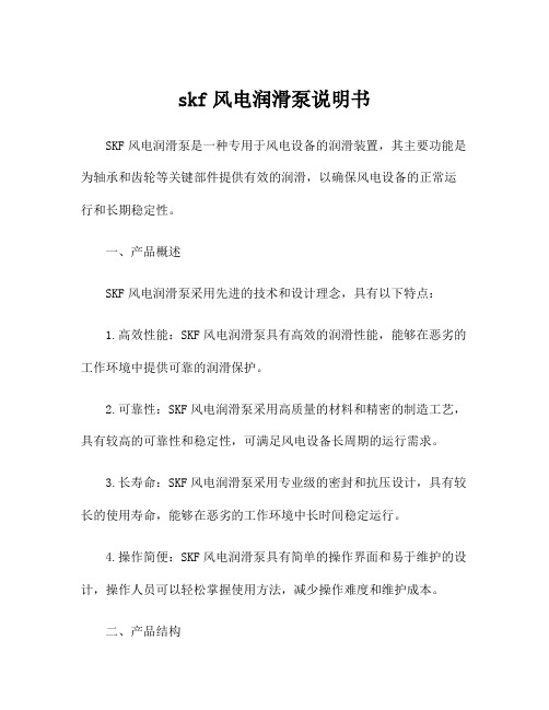
skf风电润滑泵说明书SKF风电润滑泵是一种专用于风电设备的润滑装置,其主要功能是为轴承和齿轮等关键部件提供有效的润滑,以确保风电设备的正常运行和长期稳定性。
一、产品概述SKF风电润滑泵采用先进的技术和设计理念,具有以下特点:1.高效性能:SKF风电润滑泵具有高效的润滑性能,能够在恶劣的工作环境中提供可靠的润滑保护。
2.可靠性:SKF风电润滑泵采用高质量的材料和精密的制造工艺,具有较高的可靠性和稳定性,可满足风电设备长周期的运行需求。
3.长寿命:SKF风电润滑泵采用专业级的密封和抗压设计,具有较长的使用寿命,能够在恶劣的工作环境中长时间稳定运行。
4.操作简便:SKF风电润滑泵具有简单的操作界面和易于维护的设计,操作人员可以轻松掌握使用方法,减少操作难度和维护成本。
二、产品结构SKF风电润滑泵主要由泵体、泵盖、电机、润滑油箱和控制系统等组成。
泵体和泵盖由高强度的铸铁材料制成,具有良好的密封性能和耐腐蚀性能。
电机采用高效、低噪音的设计,可在长时间运行时保持较低的能耗。
润滑油箱采用不锈钢材料制成,具有较大的容量和良好的耐高温性能,能够满足风电设备长时间运行的润滑需求。
控制系统采用先进的自动化技术,可实现润滑泵的远程监控和自动调控,提高工作效率和稳定性。
三、产品使用SKF风电润滑泵适用于各类大型风力发电设备,包括风轮、变桨机构、轴承等关键部位的润滑,可以有效减少设备的摩擦磨损和故障率,延长设备的使用寿命和可靠性。
产品使用前,请按照以下步骤进行操作:1.检查润滑泵的泵体和泵盖是否完好无损,有无松动和渗漏现象。
2.检查润滑油箱的液位,确保润滑油充足。
3.连接电源,并调整控制系统的工作参数,如润滑频率和润滑时间等。
4.启动润滑泵,并观察润滑油的流动情况和液位变化,确保润滑效果正常。
5.定期检查润滑泵和润滑油箱的清洁情况,并及时更换润滑油。
四、维护保养SKF风电润滑泵在使用过程中,需要进行定期维护和保养,以确保其正常运行和长寿命:1.定期检查润滑泵的泵体和泵盖,清洁工作面,确保密封性能和稳定性。
润滑系统操作保养规程
润滑系统操作保养规程润滑系统是机械设备的重要组成部分,对于设备的正常运行和寿命都起到了至关重要的作用。
因此,正确的操作保养润滑系统,对于设备的稳定运转及设备寿命的延长具有重要意义。
以下是润滑系统操作保养规程。
润滑系统的种类润滑系统通常可以分为油液润滑系统和油雾润滑系统两种类型。
油液润滑系统是通过油泵将注入油箱的润滑油引入润滑系统,对设备进行润滑。
而油雾润滑系统则是在润滑点上喷洒油雾,并在设备运转中通过空气的运动带动油雾到设备的润滑表面,以起到润滑作用。
润滑系统的操作及保养润滑系统的操作及保养需要按照以下步骤进行。
1. 确认润滑系统种类在进行润滑系统的操作及保养前,需要先确认润滑系统的种类,以便进行相应的操作。
2. 下机前检查油液情况在机器下机前,需要检查油液情况,判断油液是否正常、油面高度是否达到标准线,如果油面过高,需要及时将多余的油排除掉,如果油面过低,则需要填充足够的润滑油。
3. 操作润滑系统在进行机器操作之前,需要进行润滑,对润滑点进行润滑,同时检查润滑点是否有异常情况,如果有异常情况需要及时处理。
4. 保护润滑系统在设备停机后,需要保护润滑系统,清洗润滑系统,并进行保养,如更换润滑油,更换润滑器等。
长期不使用的机器在运行之前,需要进行润滑系统的清洗,排出旧油,并充入新鲜的润滑油。
5. 日常保养在日常使用中,需要对润滑系统进行定期的检查、保养,如检查润滑油、润滑器、导管等,以保证机器处于良好的机械状态,并随时保持润滑系统的正常。
预防润滑系统出现故障润滑系统出现故障,一般是由以下原因引起的。
1. 油液质量不好在润滑系统中,油液的质量是非常重要的,油液质量不好,会导致设备运行时出现过度磨损、氧化等现象。
2. 油液油面过高或过低油液油面过高或过低都会对润滑系统造成较大的影响,油面过高会影响到设备的正常运行,而油面过低则会导致设备在长期的运行中出现过度磨损的情况。
3. 油液污染润滑系统的工作环境尘土较多,如果相应的过滤系统不好,则容易导致油液造成污染,影响设备正常运行。
风力发电机变桨系统维修手册

风力发电机变桨系统维修手册第一章:引言风力发电机变桨系统是风力发电机的一个重要组成部分之一,它起着控制叶片角度,以适应不同风速条件下的发电性能和安全运行的作用。
本维修手册旨在提供风力发电机变桨系统的维护和维修指南,帮助维修人员提高工作效率和安全水平。
第二章:变桨系统所含零件及原理2.1 主轴承主轴承是风力发电机变桨系统中的关键零部件之一,它承载了叶片和叶轮的重量,并传递叶片的转动力矩。
维修人员在进行变桨系统维护时应重点关注主轴承的润滑情况和振动状态。
2.2 变桨电机变桨电机是控制叶片的角度,实现风力发电机输出功率最大化的核心部件。
维修人员需要检查变桨电机的电气连接和工作状态,并做好安全防护措施。
2.3 叶片叶片是风力发电机转换风能的重要部分,其角度的变化直接影响到风力发电机的发电效率和运行稳定性。
维修人员需定期检查叶片的表面状态和叶片与机身的连接情况,并及时清理叶片上的杂物。
2.4 变桨系统控制器变桨系统控制器是整个变桨系统的“大脑”,它通过感知风速和风向等参数,判断叶片角度的调整,并与主控系统进行通讯和协调。
维修人员应熟悉控制器的操作和故障排除方法。
第三章:维修工具和安全要求3.1 维修工具维修风力发电机变桨系统需要一些特殊的工具和设备,如扳手、电动工具、绝缘手套等。
维修人员在操作过程中需正确使用这些工具,确保自身安全。
3.2 安全要求风力发电机变桨系统涉及到高处作业和电器维修等风险较高的环境,维修人员需要严格遵守相关的安全规定。
在进行维修工作之前,维修人员应进行必要的安全培训,并佩戴个人防护装备,如安全帽、防护眼镜等。
第四章:维修流程4.1 维修前准备维修人员在进行维修工作之前应详细了解故障现象和维修范围,并组织所需的工具和设备。
4.2 维修步骤根据具体的故障情况,维修人员需要依次进行故障排查、零部件更换或修复、系统调试等工作。
在进行维修操作的过程中,应注意操作规范和安全措施,确保维修效果和人身安全。
SKF轴承维护和润滑4
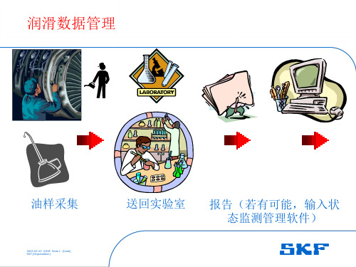
SKF轴承生命周期第五步 – 状态监测
2022-03-23 ©SKF Slide 3 [Code] SKF [MOarignatennisaantcioenP]roducts
基本仪表和仪器 –温度/热像、转速、声音、检漏、油质……
接触式测温
- TMTP 200 - TMTP 200Ex
双通道测温 - TMTL 2400K
内置标准自动评判机器(轴承) 工作状况,为现场测量人员带来 极大的便利
振动速度有效值 ISO 2372标准 自动评判结果
多参数自动测量(可一次采集以下数据) 振动总值: 速度、加速度、位移(RMS
值、峰值、峭度因子CF) 加速度包络gE值:四个频段滤波器(SKF
技术)
好处: 多参数同时测量可节省测量时间
工厂设备:轴承(机床主轴)
2022-03-23 ©SKF Slide 29 [Code] SKF [Organisation]
工厂设备:轴承
2022-03-23 ©SKF Slide 30 [Code] SKF [Organisation]
工厂设备:齿轮
2022-03-23 ©SKF Slide 31 [Code] SKF [Organisation]
掌上分析仪MicroVibe P
适合中小企业/车间进行状态监测与故障诊断的理想仪器
特点:
❖ 可测量:振动总值/时域波形/FFT频谱/加速度包
络gE值 频谱:400线、800线、1600线
❖ 数据可通过软件存储到PC上 ❖ 有自动判断功能(内置ISO 2372,SKF加速度
包络gE标准)
❖ 可接耳机进行听诊 ❖ 自由选择掌上机:HP IPAQ Pocket PC、
2022-03-23 ©SKF Slide 6 [Code] SKF [Organisation]
偏航变桨器使用维护保养手册(20100726修改定)
风电偏航和变桨减速器使用维护手册(2010版)目录1.概述 (3)2.主要技术参数 (4)3.供货状态 (6)4.包装、运输、接收、储存 (7)5. 安装 (10)6. 润滑 (11)7. 检查 (15)8.维护检修 (15)9.润滑油更换 (17)10.减速器的拆卸 (18)11.问题及相关的解决措施 (19)12.螺栓、螺塞装配及拧紧力矩要求 (19)13.风电偏航和变桨减速器用润滑油和润滑脂厂家牌号对照 (21)一、概述1.前言感谢您选择我公司产品,非常荣幸能为您介绍我公司偏航和变桨减速器产品使用及维护有关的注意事项,希望我们的产品能够使您满意。
2.说明此手册提供给用户在安全使用条件下正确安装、使用和维护我公司产品的必要的信息。
3.保修条件我公司产品的免费保修时间按与贵公司签定的协议执行。
保修不包括由于使用不当或者不正确安装所产生的损坏。
保修期内如果在使用过程中产品的质量出现问题,请通知我公司售后服务部门进行处理。
减速器必须使用在适合的工作环境以及与产品工作时预先设计的使用系数一致。
严禁不正确的安装和使用减速器。
任何在没有我公司授权的前提下更换产品零件所引起的意外损失,我公司不承担任何刑事或民事责任,同时使得保修无效。
4.注意事项操作人员必须知道关于使用减速器的安全事项:1)意外风险。
2)安全防护装置用于确保操作者安全(个人保护装置有:护目镜,手套,安全帽,安全保险索等)3)在这里我们将遵循一般的安全防护原则或者是国家早已制定了并且得到了法律认可的原则。
4)当您接收货物时,请确定产品并没有在运输过程中损坏,同时所有的配件都是齐全的。
5)在工作前,操作者必须了解本减速器的机械性能,同时已完整的阅读过此手册。
5.产品的版权限制我们公司将保留所有的权利。
禁止复制本产品或其中的某一部分结构以及本手册,除非得到了我公司的授权。
6.修订若产品的性能改变或更换,我们将发布相应的修订后的手册。
二、主要技术参数1.简介我公司每个产品都配有一个明确的铭牌及我公司标识信息。
skf风电润滑泵说明书
skf风电润滑泵说明书
SKF风电润滑泵是用于风力发电机组的润滑系统的重要组成部分。
它主要用于输送润滑油到发电机组的各个润滑点,确保机械零
部件在运转过程中得到充分的润滑和冷却。
以下是关于SKF风电润
滑泵的一些说明:
1. 技术参数,SKF风电润滑泵通常具有一定的额定流量、额定
压力和工作温度范围。
具体的技术参数可以根据不同型号的润滑泵
而有所不同,通常可以在产品说明书或者相关资料中找到。
2. 结构特点,SKF风电润滑泵通常采用高性能的泵体和密封件,以确保在恶劣的环境条件下仍能可靠运行。
泵的结构设计通常考虑
到了风力发电机组的特殊工作环境,比如防尘、防水、抗腐蚀等特点。
3. 使用方法,润滑泵的安装、调试和维护对于风力发电机组的
正常运行至关重要。
在使用SKF风电润滑泵之前,需要详细阅读产
品说明书,了解正确的安装方法、使用注意事项和维护周期。
4. 故障排除,润滑泵在使用过程中可能会出现各种故障,比如
泵体堵塞、密封件老化、泵轴磨损等。
在出现故障时,需要及时进
行排除,以免影响风力发电机组的正常运行。
总的来说,SKF风电润滑泵是风力发电机组中不可或缺的部件,它的正常运行对于整个发电系统的稳定运行具有重要意义。
因此,
在选择、安装和使用润滑泵时,需要严格按照相关的要求和说明进
行操作,以确保其性能和可靠性。
SKF轴承维护手册说明书

BIBLIOGRAFIAManual SKF de Mantenimiento de rodamientosManual de rodamientos NSKCatálogo general SKF y CDManual de Instalación y Mantenimiento de Motores de InducciónManual de Motores eléctricos WEGFundamentos y componentes de la OleohidráulicaMantenimiento de equipos hidráulicos. Franz X. FeichtMantenimiento de sistemas hidráulicos. Ing. Diego BernhardtMantenimiento de sistemas neumáticos. MicromecánicaReparación de componentes neumáticos. MicromecánicaAdministración Moderna de Mantenimiento. Lourival Tavares (digitalizado)Modelos Mixtos de Confiabilidad. Luis Amándola, Ph.D(digitalizado)Mantenimiento su implementación y gestión. Leandro Torres(digitalizado)Sistemas de Mantenimiento Planeamiento y control .Duffuaa Salih O.Mantenimiento Industrial. Gatica Ángeles Rodolfo.Ingeniería de Mantenimiento. Cruz Rabelo. Ed. Nueva ArgentinaMantenimiento de máquinas eléctricas. Manzano Orrego.Ed. Paraninfo.Revistas de Club de mantenimientoo Gestión estratégica de activos de mantenimientoLourival Tavareso Mantenimiento, su implementación y la introducción de mejoras en la producciónLeandro Torreso Elementos de medición y análisis de vibraciones en máquinas rotatoriasEvelio Palomino MarinSETEC COMSET BOLIVIAo El libro de RCM II RELIABILITY CENTRED MAINTENANCETraducido por Ellmann y asociadoso Administración Moderna de MantenimientoLourival Tavareso Sistemas de Mantenimiento Planeación y controlDuffuaa Salih O.Gentileza de DTI - Libros, Videos y Documentos Técnicos.o Mantenimiento IndustrialGatica Ángeles Rodolfo R.Gentileza de DTI - Libros, Videos y Documentos Técnicos.o Dirección y Gestión de paradas de plantaLuis AméndolaEdiciones Espuela de Planta, Sevilla, Españao Modelos Mixtos de ConfiabilidadLuis AméndolaEL MANTENIMIENTO EN TENARIS TENARIS UNIVERSITY 1MANTENIMIENTO DE MAQUINAS ELECTRICAS. MANZANO ORREGO, JUAN JOSE 8MANTENIMIENTO INDUSTRIAL. GONZALEZ, RAIMUNDO HEBER. 1MANUAL DE MANTENIMIENTO DE RODAMIENTOS. SKF ARGENTINA S.A. 1MANUAL DE MANTENIMIENTO INDUSTRIAL. MORROW, L. C. 3MANUAL SKF DE MANTENIMENTO DE RODAMIENTOS. SKF 1。
发动机润滑系统维护保养的操作流程

发动机润滑系统维护保养的操作流程下载温馨提示:该文档是我店铺精心编制而成,希望大家下载以后,能够帮助大家解决实际的问题。
文档下载后可定制随意修改,请根据实际需要进行相应的调整和使用,谢谢!并且,本店铺为大家提供各种各样类型的实用资料,如教育随笔、日记赏析、句子摘抄、古诗大全、经典美文、话题作文、工作总结、词语解析、文案摘录、其他资料等等,如想了解不同资料格式和写法,敬请关注!Download tips: This document is carefully compiled by theeditor.I hope that after you download them,they can help yousolve practical problems. The document can be customized andmodified after downloading,please adjust and use it according toactual needs, thank you!In addition, our shop provides you with various types ofpractical materials,such as educational essays, diaryappreciation,sentence excerpts,ancient poems,classic articles,topic composition,work summary,word parsing,copy excerpts,other materials and so on,want to know different data formats andwriting methods,please pay attention!发动机润滑系统维护保养操作流程详解发动机润滑系统是汽车的心脏的重要组成部分,它负责减少发动机内部零件的磨损,提高其工作效率。
- 1、下载文档前请自行甄别文档内容的完整性,平台不提供额外的编辑、内容补充、找答案等附加服务。
- 2、"仅部分预览"的文档,不可在线预览部分如存在完整性等问题,可反馈申请退款(可完整预览的文档不适用该条件!)。
- 3、如文档侵犯您的权益,请联系客服反馈,我们会尽快为您处理(人工客服工作时间:9:00-18:30)。
14
深圳市南山区建工村建厂路 32 号 TeL:0755-86021610 Fax:86060166
KFG(VPBM)系统使用手册
二:VPBM分配器 2.1概述
15
深圳市南山区建工村建厂路 32 号 TeL:0755-86021610 Fax:86060166
KFG(VPBM)系统使用手册
2.2:结构示意
更换缺陷泵
插上插头并拧紧 (螺丝拧到底)
故障
虽然泵在运转,但油泵没有一点润滑剂流传 用电表检查额定电流
原因 空油瓶,插座上连接线错误或有缺陷
油脂盘倾斜
纠正 纠正或修理连接线
更换油脂泵
10
深圳市南山区建工村建厂路 32 号 TeL:0755-86021610 Fax:86060166
A 接 6mm 管 P 接泵芯螺纹
R 管路堵塞后的油脂
13
深圳市南山区建工村建厂路 32 号 TeL:0755-86021610 Fax:86060166
KFG(VPBM)系统使用手册
1.10 技术 允许运转温度 类型 油箱容量 油箱材料
保护类型 DIN40050,T9 运行模式/运行时间参考 VDE0530/DIN41756
带压盘自动加油脂器
1.1概述
1.2安全指南
1.3认可的润滑剂
1.4安装
1.5启动
1.6故障
1.7KFGS 12/24 VDC 系列内置控制器1.8泵单元
1.9安全阀
1.10技术说明
二:VPBM分配器
2.1概述
2.2:结构示意
三:系统示意图
2
深圳市南山区建工村建厂路 32 号 TeL:0755-86021610 Fax:86060166
本系统在出厂设定值为:工作1.2分钟,间隙7小时
11
深圳市南山区建工村建厂路 32 号 TeL:0755-86021610 Fax:86060166
KFG(VPBM)系统使用手册
1.8 泵单元
KFG 泵装置设有 3 个润滑输出口,可同时安装一到三套泵单元;每组泵单元 均可与递进式分配器连接组成独立的润滑油路. 当 3 个润滑输出口未能全 部使用时 ,多余的输出口可用以下件封堵:螺堵 M20X1.5 垫圈 20。泵单元订 购时必须确认。
型号
KFG1.U1 KFG1.U2 KFG1.U3 KFG1.U4
给脂量 ml/min
2. 5 1. 8 1. 3 0. 8
标记号
1 2 3 4
1. 螺堵
2. 管接头
3. KFG1.U3 泵 芯
12
深圳市南山区建工村建厂路 32 号 TeL:0755-86021610 Fax:86060166
KFG(VPBM)系统使用手册
检查电压,用手启动磁性转子几次,如果电压正 常,磁性转子移动,更换磁性转子,如有必要更 换减压阀
泵芯缺陷(当主管路被关闭时,用一个手指封住出 填充油脂,注意容器上刻度标记
口可以得到确认)
调换泵芯
空油箱,接触点缺陷 空油箱,插头松开
注意 如果油箱是空的,用一根细的压力弹簧使泵单元工 作的泵芯的更换是唯一可行的
用 1 个转换点控制的油位开关
用 2 个转换点控制的油位开关
油位最低的开关位置
油位最低的开关位置
油位最高之上的开关位置
油位最高的开关位置
类型 开关能力 转换最大电压 转换电流 连接插头 插头/插座型号
弹簧片接触 60W/VA 230V AC/DC 1A DIN 43 650 IP 65
在油位最高和最低之间的开关
类型 开关能力 转换最大电压 转换电流 连接插头 插头/插座型号
弹簧片接触 60W/VA 230V AC/DC 1A DIN 43 650 IP 65
8
深圳市南山区建工村建厂路 32 号 TeL:0755-86021610 Fax:86060166
KFG(VPBM)系统使用手册
用 3 个转换点控制的油位开关
三位LED 显示屏
显示 功能
涵义
正常状态下,显示屏关闭, 可以按下“上、下” 键激活, 可显示当前值和设定值。在设 定运行参数时,会 显示用户信息。
t=计时 PA= 暂停
控制器在计时运行模 式,且处于暂停状态
润滑循环过程的一部分 输入及显示单位:小时
c=计数PA= 暂停 t=计时CO= 接通
控制器在计数运行模 式,且处于暂停状态
原因
没有注意填充物的最大刻度 在圆盘上密封翻起或泄漏
纠正
清洁泄露的润滑剂,检查圆盘密封性能 视觉检查是否密封圈翻起或损坏,如检查结果
确实如此应更换油脂泵
在油脂装填时空气没有排尽 减压阀没有关闭
润滑剂液位在最低位置之下
沿着泵各自的主管路逐次让泵启动排出管路 的气泡直到油脂排出
用 2 个转换点控制的油位开关
油位最高的开关位置
油位报警开关位置
1.5 启动 1.5.1 油位监视 从油位开关拔出连接插座
依靠它的设计(看系统/机器操作指令),系统的监控设备 会发出一个错误信号! 将连接插座安装在油位开关上 1.5.2 润滑剂的填充 单独的部件看 Vogel 的印刷品 1-9430,第 51 页 在加油泵上配有连接插头 995-001-500
注!列表上的润滑剂是由设备和车辆制造商认可的。 润滑剂引起的环境危害
推荐的润滑剂的成分由制造商按照当前的安全规则生产,油和油脂是危害土地和水源的物质,所以在储存、处理、运输需要满足特殊的安 全规则。
运输储存
KFG 和 KFGS 系列泵按照 VDA6-01 和 DIN ISO9001 及接受国的规则进行销售包装。 对于公路运输、空运、海运没有限制。 保存在摄氏-40 度和 70 度间干燥的地方。 包装好的货物必须小心搬运!
油位报警开关位置
油位最低的开关位置
油位最低的开关位置 类型 接触 开关能力 转换最大电压 转换电流 连接插头 插头/插座型号
弹簧片
60W/VA 10-30V AC/DC
1A DIN 43 650 IP 65
类型 触 开关能力 转换最大电压 转换电流 连接插头 插头/插座型号
弹簧片接
60W/VA 230V AC/DC
1.4.5 润滑脂泵的电气连接 看 KFG,KFGS 操作说明书,文件编 号为 951-130-184
注意 连接线应与技术说明书以及本地 的状况和管理相一致 (e.g.DIN,VDE).
1.4.6 安全阀电气连接 技术资料看第 13 页
图 4. 泵单元的安装孔
图 5.安装尺寸 填充量
4 6 8 10
承压系统危险系统可能带压力的,所以在开始检修、调整、或进行相关操作前必须卸压。
4
深圳市南山区建工村建厂路 32 号 TeL:0755-86021610 Fax:86060166
KFG(VPBM)系统使用手册
1.3 认可的润滑剂
NIGL2 号以下油脂,DIN 51818,或最大流体压力为 700mbar. 可选润滑剂清单会不断更新
应用领域
Vogel KFG 和 KFGS 系列泵应用于车辆、设备、机床的集中润滑系统。输送油脂黏度达到 NIGL2。任何超出此应用范围的被视为不按照指定应用条件。
授权安装技师
只有有资质的工程师可以安装、操作、维护和修理本指南涉及的部件。有资质的工程师是指经过培训,由设备用户指定或委任的人员,此类人员接受培训、具有 经验、了解操作指南,熟悉相关的标准、规则、事故预防、故障排除及操作运行状况。
控制器在计时运行模 式,且处于运行状态
润滑循环过程的一部分控制器记外部脉冲 调节器的脉冲并与设定值比较
CONTACT= 时间 (当泵输送) 输入及显示单位: 分钟
c=计数 CO= 接通
C=循环O=关闭P= 压力
控制器在计数运行模 式,且处于运行状态
显示监控设置
CONTACT= 时间 (当泵输送) 输入及显示单位:脉冲
马达寿命
出口数量 如果少于3个出口,必须用螺堵。 最多3个
润滑剂 NLGI含有极压添加剂的1-2号油脂
-25 to 75 KFG(S)1-5 2L PA6i
IP 5K6K S1 持续运转
3000小时
-25 to 60 KFG(S)3-5 6.3L PMMI
KFG(S)5-5 10L PMMA
IP 5K6K -25- +40 S1 持续运转 40-+60 运转时间 0-10 分钟 最小暂停时间=4个运转时间 运转时间10-15分钟,最小暂 停时间=2小时
1.9 安全阀
单独的安全阀溢流阀直接安装于泵单元出口,保护整个润 滑系统免受过高的压力。溢流阀的开启压力为 300bar。
如系统中递进式分配器或润滑点发生堵塞,导致系统压力 高于 300bar,则溢流阀自动开启卸油。
订货号 161-210-012 161-210-016
连接管 径 ф6
ф10
调整压(bar) 300±20 300±20
泵单元 电气泵单元连接 电气安全阀连接 电气油脂液位开关连接
泵单元必须被安装在泵的底部朝外的风能系 统的旋转部上,那么它的离心力是从泵盖到泵 的底部沿着轴的方向被发散
6
深圳市南山区建工村建厂路 32 号 TeL:0755-86021610 Fax:86060166
KFG(VPBM)系统使用手册
泵安装应尽可能的安装于不易受 1.4.4 泵单元安装尺寸 外界侵扰.或损坏的适当位置,设备 上的安装孔按提供的图示钻取
1A DIN 43 650 IP 65
图 8. 用加油连接头填充油脂
9
深圳市南山区建工村建厂路 32 号 TeL:0755-86021610 Fax:86060166
KFG(VPBM)系统使用手册