单路继电器说明书
继电器、开关和按钮说明书

䘀䄀䜀伀刀㈀ 㤀䰀䄀嘀䄀䜀䜀䤀伀 䈀䤀䄀一䌀䠀䔀刀䤀䄀 ⴀ 䰀䄀唀一䐀刀夀Switches, Push Buttons, Selectors12039115Z213033000Momentary push switch orange 22x30 mm16A 250V; faston 6,3x0,8 mm37446912024040120299111203108112111795R663031000RT30280551Z203050000Contactor K3-10ND10 190R TX4kW 3P; 200-240V 50-60Hz 400V - 3 cont.NO + 1 aux NO51717012024011Z213007000Mini contactor B7-30-10-F220-240V 40-450Hz; dim. 47x48x42,5 mm37388312024039Z743009000Contactor 3RT1016-2AP029kW 3P; 230V 50/60Hz 400V - 3 cont. NO + 1 aux NC37389212024075X183011000Contactor 3RT2024-1AL205,5kW 3P; 230V 50-60Hz 400V cont. 3 NO dim. 45x91x88 mm37573612041014Contactor 3RT2024-2AL205.5kW 3P; 230V 50/60Hz; 400V 1NO + 1NC; dim. 97x35x102 mm42629612024012Z683087000Contactor 3TF2001-3AL24kW 3P; 230V 50/60Hz; 400V 3 NO + 1NC37388412023706Z203062000Z683027000Relay 2 contacts NO 230V 50/60Hz 16A 250Vwith DIN bar adaptor37380412025218P620526000Snap action microswitch with lever 4,3X27 mm37431012025193R010534000Snap action microswitch with roller 16A 250Vleverage L=25 mm; 1 contact NO, 1 contact NC30583712024176Z273016000Limit switch microswitch 6A 250V IP6637393812032827DO1FB02230Magnetic microswitch M12x1 L=45 mm 1NO; 50W 1A; cable L=500 mm584470120244776021130029SAVW250030Z203009000Magnetic microswitch A061 1V NO 250Vac 0,004Abulb Ø 6x29 mm - cable L=240 mm37407712114100Magnetic switch M12x1 10÷30Vdc cable L=2000 mm42911912090513DO1DG11734Magnetic microswitch 230Vdim. 10x32x5,5 mm; cable L=500 mm43385512023211P613002000Door electromagnet 36Vdc cable L=100 mm373666120335784GH49G001Floating ball for level regulator Ø 69 mm INOX58344612024066Z203010000Magnet switch support dim. 34,5x19,5x8,5 mm37389912009985R010535000Plate for microswitch dim. 45x30x2 mm3730581203716512168683DO1DL14150Terminal board 4 mmq 600V 20A5844691202834812029280DO1AB01460DO4PRS0041Pressure switch 0,2mbar 1NC, 1NO; Pmax 150mbar5844661203202612049069DO1AB01439DO1AB01475Differential pressure switch 0,4-6 mbar374376120300051203818312147265Pressure switch 20...300 Pa5825251202386212031028120334726021050008RT31011008Z103066000Compact fan 120x120x38 mm - 20W 230V 50/60Hzno cable; faston connection 2,8x0,5 mm; 2550 rpm; ball bearing531364Motors121491601DC07288Gearmotor 3 phase 550W58520912087148DO1DC07056Gear FRC050 Ø 14/25 mm reduction rapport 1:30583604120275731204903412087150DO1DC07052DO1DC07055DO1DC07057Motor 3 phases 370W 230/400/460V 50/60Hzshaft Ø 14x30 mm58315512023189P645902000Motor 3 phases 3000W 230V 60Hz 3548rpm; cable L=260 mm37366212023194P635906000Motor 3 phases 2200W 230V 50/60Hz 2800rpm37366312024916P666014000Retaining ring Ø 125x150x12 mm RG37421712023457P666021000Shaft sealing Ø 125x150x12 mm VITON42281912147306Electromagnetically released spring breake 85W 205Vdc 235NM cable L=660 mm58385712041867Drain pump 30W 220/240V 50Hzinlet Ø 24 mm, outlet Ø 24 mm - Faston 6,3x0,8 mm459511Heating Elements12024214Z121741000Boiler heating elements 9000W 230V L=540 mm, triangular flange H=90 mm, with gasket37396012032899DO1AC02259Heating element 2000W 230Vdim. 540x45 mm; connection M12x1; faston 6,33743811202481612096226P613008000Heating element 2000W 230V UL dim. 265x65 mm; flange 81x28 mm; faston 6,3 mm42891312023247120960234XFP623005000P623005000SAVW130003SAVW130014Heating element 3000W 230V UL dim. 275x65 mm; flange 81x28 mm; faston 6,3 mm428918120232424XFP183002000P633002000Heating element 4000W 230V UL dim. 355x65 mm; flange 81x28 mm; connection M43736701202457712041359P533001000P6330111000Heating element 6000W 230V UL dim. 510x65 mm; flange 81,3x28 mm; faston 6,3 mm37410812024721Z129502000Boiler heating element 12000W 230VUL L=550 mm; triangular flange 92,5x89,7 mm; Øint. 60 mm; with bulb housing L=180 mm; connection M437416812024645Z203601000Tank heating element 2800W 230V dim. 365x102 mm; flange 70x18 mm37413312024282Z101723000Heating element cover Ø 63x67,5x55,3 mm373992Cables12025061P643005000Cable3742531214071212148198GHZ23C01Power supply cable L=4000 mm eyelet Ø 4,2 mm58370812023814P503025000Bi-metal thermostat NTC 50kohm3738421209501812096597Bi-metal thermostat 110° 250V 10A faston 6,3 mm4290161203243212032731DO1AG11130DO1DG11130Safety thermostat 1P 0÷90°Ccoated capillary L=3000 mm; bulb Ø 6x93 mm; D-shaft Ø 6x4,6 mm3743771209761112126296DO1DG11135Safety thermostat 1P 220°Ccapillary L=1900 mm, bulb Ø 6x58 mm, 16A 240V58258512023546Z953003000Gasket Ø 11x27x8,5 mm373738Drain valves12024781P302120000Electric drain valve N.O. 220/240V 50/60Hznormally open; inlet Øext 50 mm; outlet Øext 50 mm; overflow pipe Øext 35 mm; mod. MDB-O-23741891202626712147216SAVZOD0112SAVZOD0264Electric drain valve N.C.coil 230V 50/60Hz 0,20-0,17A; inlet Ø 76 mm; outlet Ø 80 mm; overflow pipe Ø 35 mm583854Drain valves12137690Electric drain valve N.O. 230V 50/60Hz Ø75,5 mm - Ø 79,5 mm42670912024404P532103000Electric drain valve N.O. 230V 50/60Hz 0,20-0,17Ainlet Ø 76 mm; outlet Ø 80 mm; overflow pipe Ø 35 mm37405212093146Air brake4299221070312025161Z701135000Solenoid valve 180° - 1 way - 220/240V 50/60Hz - Ø 10,5 mmwith fastons; inlet Ø 3/4" with filter; Tmax 90°C43540912023794P255001000Solenoid valve 180° - 2 way - 220/240V 50/60Hz - Ø 10,5 mmwith fastons; inlet Ø 3/4" with filter and reducer 14 lt/min; Tmax 90°C3738311202392112115418P443018000P443073000Z6111223000Z611123000Solenoid valve 180° - 3 way - 220/240V 50/60Hz - Ø 10,5 mmwith fastons; inlet Ø 3/4" with filter; Tmax 90°C2001211202408312097038P443042000Outlet pressure reducer 2,5 lt/min [brown-Inv]20011812041072Solenoid brass valve G1" - 4W 230V 50/60Hz43001112157686Electro-pneumatic valve 4/2dim. 3,5x1,8x51,5 mm583864Solenoid Valves and Reducers12028386QUINCA0161Solenoid valves 230Vac 50/60Hz 3/2 NC58386512023551Z102305000Solenoid body EV220B 3/4"L=90,5 mm37374012008907S205023000Nipple 1/2"÷1/2" - L=27 mm - brass51924912018536S102122000Rubber holder 1/2'' - outlet Ø 9 mm Ltot.=67 mm37343112009102Pipe fitting 90° 1/2"M58231412019829U565032000Rear left pipedim. 545x70xh95 mm37351312019731U565031000Rear right pipeØ4 mm; dim. 545x100x75 mm3735071202502612152912P630704000Formed hose 90°Øint.72 mm; dim. 400x130 mm45974712044165Formed hose Øint. 75 mm427755Hoses110000663702400000Hose EPDM Ø 5x12 mm L=2300 mm Tmax 110°C435233110000833676900003676900000S102121000Z271101000Z631121000Hose EPDM Ø 10x17 mm (sold by meter)Pmax 10 bar; working temp. -35°C÷110°C61236012024115Z602121000Rubber feeder hose 3/4" L=1500 mm straight connection + 90° plasticconnection; ring nut in nickel-plated brass Ø3/4"F; pipe Ø 13x19 mm; Pmax 10 bar;Tmax 90°C; WRC/WRAS/VDE approved52432412007747P634021000Drain pipe Ø 50x60 mm dim. 620x220x140 mm42311712023666Z220903000Drain pipe PPE Ø 19 mm 90°+ Ø 22 mm 180° L=2000 mmmuffs 180° Ø int/ext 19/24 mm, muffs 90° Øint/ext 22/27 mm, Øext hose 24 mm37072312022957Drain box58523112023537Z710708000Ring nut 1" 1/2H=15 mm; CH5037373712038179DO1SK00016Air filter Ø 260x430 mm374433Transmission components12023273P615902000V-ribbed belt L= 1300 mm 8 ribs37367912023269P625903000V-ribbed belt L=1600x18,8x3,5mm 8 ribs37367712007744P635908000V-ribbed belt L=1663x3,5x28,4 mm 12 ribs58303212049376V-ribbed belt L=1752x3,5x19mm 8 ribs42636812018841P645901000V-ribbed belt L=1854x3,3x19 mm 8 ribs37345812046375V-ribbed belt L=1992x3,5x28 mm 12 ribs42636612023249P646013000Drum pulley31965712023222P540702000Ice containerdim. 190x470x305 mm42339212128087Rep cierre ln-35dim. 800x765 mm428706Structural components12003389Z270337000Paneldim. 560x116x18,5 mm42199312023338P620504000Door handle 100x90 mm37368712147485Door handle58386112025202P620514000Shaft Ø 6x55 mm37430312023239P620527000Semicomp door. fagor 13.1837366812023347P620505000Hingeshaft Ø 6x15 mm37369112030807K005B50072Manometer Ø 62 mm 0 ÷ -1bar58495212010155Q302061000Snap ring Øint. 6x0,7 mm37313412009802Q301036000Snap-ring Øint. 103 mm37299812010103Q272020000Radial snap ring INOX Øest 9x0,8 mm43824512023427P620525000Ring Øint. 12,5 mm wire Ø 1,3 mm58200612025215P610506000Bush Ø 6x12x12 mm37430812025100P680511000Bushing Ø 16x22/28x25 mm42289912010251Q222012000Hexagonal nut M6x8 self-locking - INOX36294312009839Q162020000Hexagonal nut M4 - H=3,2 mm INOX CH736294012010284Q162030000Hexagonal nut M5 - H=4 mm INOX33704512010036Q881302000Hose clamp Ø 12÷22/9 mm - INOX43848012009997Q881305000Hose clamp Ø 25÷40/9 mm - INOX44169912009986Q881306000Hose clamp Ø 32÷50/9 mm - INOX43846412009962Q881307000Hose clamp Ø 40÷60/9 mm - INOX518655120009933Q881324000Hose clamp Ø 50÷70/12 mm - INOX43846312145377Support42727312009953Q242010000Tooth lock washer M358185912009928Q242020000Tooth lock washer Ø int.4/est.7,8 mm INOX37303812009872Q262040000Grower washer Ø 6,3 mm INOX35821112009944Q232030000Flat washer Ø 5,5x10x1 mm - INOX61277012010267Q302022000Flat washer Ø 6,3x15,7x1,2 mm37319912009868Q232040000Flat washer M6 Ø 6,4x11,6x1,6 mm INOX4326051201011012010268Q232050000Q302025000RT13080160Flat washer Ø 8,4x16x1,2 mm DIN125A37320012010235Q232060000Flat washer M10 INOX Ø10,6x20x2 mm32201512010278Q032021000Raised countersunk head screws M4x10 mm37320612010084Q052046000Cylinder head bolts M6x20 mm INOX37310112010226Q032031000Hexagon head screw TE M5x10 mm - INOX [10 pcs]52249712010221Q012032000Hexagonal head screw TE M5x16 mm - INOX [10 pcs]32626312010186Q011342000Q012042000Hexagon head screw TE M6x16 - INOX35811812010056Q012056000Hexagon head screw TE M8x40 mm - INOX [10 pcs]52268712010213Q032032000Flat-headed bolts TC M5x16 mm37317012010262Q042022000Countersunk screw M4x15 mm37319612009876Q151320000Sheet metal screws M4x6 mm37302212023360P666102000Bearing 125/70/3142282312023334P666101000Bearing Ø 105x190x36 mm422827120379971ED40207Bearing ucfc 207433323120039221203836412038446121278381215482213P620516013P6205310P620516000Door locking mechanism 205V dim. 180/220x100 x53 mm5824801202841112147483Door lock switch 220/240V 50Hz58386012021912P627816000Cover 120x50x2 mm58248112016778P620511000Pin for handleØ6x29 mm AISI 30337329012025182P620529000Unlocking pin Ø 7xLtot. 22,5 mm5820051202436112122779N103033000Thermostat knob Ø 72 mm D-shaft Ø 6x4,6 mm41525612024758P530503000Door glass Ø 385x55 mm37418412024250P440503000Door glass Ø 305x40,5 mm37398012024980P630111000Friction damper 140N Ø 28/185-295 mm RD10 - hole Ø 10,2 mm37423512025078P620126000Friction damper 90N Ø 28/185-280 mm37425812025077P620115000Friction damper 120N Ø 28/187-280 mm37425712147246SAV W08 0039SAVW080039Friction dumper 120N Ø 28/170-265 mm hole Ø 10 mm58385512025076P540201000P630110000Friction damper 250N Ø 28/170-300 mm hole Ø 10,2 mm37425612147247SAV W25 0006SAVW250006Friction dumper 250N Ø 28/190-280 mm hole Ø 10,2 mm5838561202349212049230P680220000Friction damper Ø 45,5xLtot. 330 mm hole Ø 10 mm42766512157708QUI NCA 0359QUINCA0359Shock absorber Ø 70xLtot. 345 mm42555112147399QUI NCA 0360QUINCA0360Gas friction dumper Ø 40x190/275 mm hole Ø 12 mm58385812147406Tension spring Ø 42x116xLtot200 mm58385912023383P620510000Spring closing37370112033583SPQ800622PFriction damper [KIT]374389Photocells1202809012147195Speed sensor M12x50 mm cable L=2000 mm58385312024424T133008000Screw M3x8 mm37405812025260T133007000Spacer L=16 mm M337432812023354P613019000Pcbdim. 235x140 mm37369312024197P613025000Pcbdim. 235x140 mm58185712025606Plc TWD LCAA dim. 70x95x90 mm58385212024780P613018000Pcbdim. 115x140 mm37418812017891P623017000Pcb with main switch dim. 50x30 mm3733831202649612147280ELEELE0089Pcbdim. 135x135 mm5852341203814712147287ELEELE0109Display board dim. 100x150 mm4333631211948812155387Display TFT 4,3"42678112043487PLC programmed 3kw (lr-25)42875612024634SAVW080104Z218030000Relay pcbdim. 75x35 mm37412812023112P640325000Pcb supportdim. 120x44x14 mm58185812023293P623026000Cable L=675 mm4533921212081512168823Pcbdim. 155x324 mm42968112024921P623023000Pcb LED37421812031344DO1DH12314Temperature probe L=175 mm bulbo Ø 4x10 mm; flange 17x10 mm42478112025036Z713028000Temperature probe NTC 64k oHm probe Ø 6x14 mm; -40 ÷ +110; cable L=300 mm3742501202948712147283ELEELE0098Temperature probebulb Ø 6x64 mm; cable L=2000 mm37435712120341Cable PTC with rectifier bridge582004Probes12024049N503017000Gasket Ø 23x35x7,5 mm3738951202672612127829DO1DC00001Inverter ABB 3P 370W 200/240V 6.1A5840111202613012026131DO1DC00003DO1DC00063Inverter ABB 3P 1100W 200/240V5844671202334312040601P623002000Inverter G110 1 phase 200/240V 47/63Hz 19,7Aoutput 3 phases 0-230V 0-550Hz 7,8A; 1,5kW 200/240; dim. 120x160x140 mm3736891203844213P6330050Inverter G110 1 phase 200/240V 47/63Hz 27,2Aoutput 3 phases 0-230V 0-650Hz 11A; 2,2kW 200/240V31783412018961P610319000Membrane keypads 640x160 mm37346412023797Z468001000Membrane keypads 45x400 mm37383212023260P636108000Gasket373675Gasket for laundry1200776712024455P440502000P610508000Oblò gasket Ø 247x305 mm37406512023284P620528000Door gasket Ø 395 mm37368012023475P660535000Oblò gasket Øext. 590x33,5 mm37371712147521Drum gasket583862O-rings12009912Q307036000O-ring 1,78x5,28 mm EPDM37303112009926Q307077000O-ring 3,00x128 mm3730371209314512122182O-ring 3,53x24,99 mm NBR410444120100401211831912154789Q307044000O-ring 5,34x56,52 mm NBR435067Flat gaskets12025148P636005000Flat gasket Ø 114x160x4,3 mm374280Laundry parts1203490812147375QUINCA0086Ironing band 105x410 mm37439610222010261202944612147376QUINCA0087Ironing band 200x1660 mm3743561203717712037305DO1KA00422QUINCA0091Polyester/Meta-Aramid guide tape 13mmx10mt Tmax 230°C331471120346231214737712147908121562021BE03500QUI NCA 0088QUINCA0088Self-adhesive elastomere strip for ironers (sold by meter))3294271202775712149876GR10003000Steel wool band width 100 mm [8 Kg]317321120299561214741412150171QUINCA0476Plush clothing 2020x495x3 mm374362。
RN-111M 单相电压保护继电器使用手册说明书

NOVATEK-ELECTRO LTDintellectual commercial electronicsRN-111MSINGLE PHASE VOLTAGE PROTECTION RELAYOPERATING MANUALReview the Operating manual before using the unit.RN-111M NOVATEK-ELECTROStore the unit in the operating environment for 2 hours before switching to the mains. Do not use abrasives or organic compounds for cleaning (spirit, gasoline, solvents, etc.).NEVER ATTEMPT TO REMOVE AND REPAIR THE UNIT. Some of the unit components may be live.NEVER ATTEMPT TO OPEN AND REPAIR THE PROTECTED EQUIPMENT, IF SWITCHED TO THE UNIT SOCKET.The electrical contact between the plug and the socket remains even in case of deactivated unit NEVER ATTEMPT TO OPERATE THE UNIT WITH THE MECHANICAL DAMAGE OF THE HOUSING.NEVER ATTEMPT TO OPERATE THE UNIT UNDER CONDITIONS OF HIGH HUMIDITY. Do not let water into the unit.WARNING! THE UNIT SHOULD BE OPERATED IN THE ELECTRIC MAINS PROTECTED WITH AUTOMATIC CIRCUIT BREAKER WITH THE BREAKING CURRENT OF 32 A, NO MORE.1. APPLICATIONSingle phase (240V/50Hz) voltage protection relay RN-111M (hereinafter RN-111M) is designed to turn OFF home used consumer equipment or industrial power load in case of unallowable voltage fluctuations. And when the voltage parameters return back to normal values after fluctuation – it automatically turns ON the power load with the user adjusted time delay.∙If power load is less than 3,5 kW (16A) then RN-111M may operate with the power load directly using its own output terminals;∙If power load is more than 3,5 kW (16A) then it should be commutated using contactor of appropriate power rating. So RN-111M operates with the magnetic coil of the contactor and thus turn ON/OFF the power load when necessary. Kindly note that contactors of appropriate power rating should be chosen by User and not supplied along with RN-111M.RN-111M has four independent modes of operation:1. Minimal/Maximal voltage protection relay;2. Minimal voltage protection relay;3. Maximal voltage protection relay;4. Turn ON time delay relay.On the LED digital display RN-111M indicates the value of acting voltage level and the Open/Close (ON/OFF) state of the output contacts.1 – Input terminals;2 – Three digits seven segment LED display;3 –Green LED indicator showing ON/OFF state of the output contacts (power load);4 – Maximal voltage tripping threshold (Umax);5 – Minimal voltage tripping threshold (Umin);6 – Autoreclosing time delay (Ton);7 – Output terminals;8 – Toggle switch (ON/OFF): Minimal voltage tripping (Umin);9 – Toggle switch (ON/OFF): Maximal voltage tripping (Umax);Figure 1- Front panel controls description and dimensions diagramNOVATEK-ELECTRO RN-111M1. TECHNICAL CHARACTERISTICS2.1 GENERAL INFORMATIONRN-111M complies with requirements:IEC 60947-1; IEC 60947-6-2; IEC 61000-4-2; CISPR 11:2004, IDT.Harmful substances in quantities exceeding the maximum permissible concentrations are not available.The main technical specifications are provided in the Table 1.Table 12.2 MAIN TECHNICAL SPECIFICATIONSMain Technical Specifications are provided in the Table 2Table 2RN-111M NOVATEK-ELECTRO2.3 PARAMETERS OF THE INTEGRATED RELAY OUTPUT TERMINALSThe parameters of the integrated relay output terminals are shown in Table 3.Table 33. START-UP PROCEDURE AND CONNECTIONing toggle switches on the front panel set necessary mode of operation ;3.2. In case of using RN-111M as Minimal/Maximal protection relay, Minimal protection relay or time relay connect wires according Figure 2,vers.a.If RN-111M is being used as a maximal voltage protection relay power load should be connected according Figure 2,vers.b.If power load is less than 16A (3,5 kW) then it could be commutated directly by the output contacts of theRN-111M; if the power load is more than 16A – then it should be commutated using contactor of appropriate rated parameters and the RN-111M should operate with the magnetic coil of the contactor.3.3. Connect RN-111M (contacts 5, 8) to the power circuit.3.4.By spinning the knobs on the front panel set the required Minimal and Maximal voltage tripping thresholds (U min and U max) and set necessary turn ON time delay (T on). Please pay attention that the T on time should be adjusted taking into consideration the technical documentation and requirements of the protected power load –for example –air-conditioners, refrigerators and other compressor containing equipment usually need 3-4 minutes pause before turn ON again after they were disconnected.3.5. Give the power supply to RN-111M and by spinning the adjustment knobs set precisely the required values for the U min, U max and T on. When spinning the knobs on the LED digital display it is shown the exact value of the adjusted parameter.4. GENERAL DESCRIPTION AND OPERATION4.1. RN-111M has several functional states:– Normal operation mode: Power load is ON, Green LED indicator –ON. Digital LED display shows measured voltage value;– Alarm mode: Power load is OFF, Green LED indicator –OFF. Digital LED display shows blinking value of the measured voltage;– Indication of the remaining time to turn ON the power load (Ton): Power load is OFF, Green LED indicator –OFF. Digital LED display shows the remaining time to turn ON the power load (in seconds) and dot is being displayed in the lower digit. After the Ton time elapse RN-111M will return to Normal operation mode if voltage parameters on the input terminals are within the permitted range adjusted by the user.4.2. MINIMAL/MAXIMAL VOLTAGE PROTECTION RELAYPower load (contactor coil) should be connected to the output terminals 2(3), 4 (Figure2).If RN-111M was initially deenergized or the power load was OFF due to the wrong voltage parameters – then after correct voltage appear on the input terminals and after the time delay T on contacts 1, 2(3) will open and contacts 2(3), 4 will close.If input voltage get lower than minimal voltage threshold for more than 12 seconds RN-111M becomes to Alarm mode– contacts 1, 2(3) close and contacts 2(3), 4 open.If input voltage gets 60V lower than the minimal voltage tripping threshold – RN-111M comes to Alarm mode in 0,2 sec. After the recovery of the voltage parameters to the value of hysteresis (4-5V) – cycle is repeated relays.If input voltage gets higher than the maximal tripping voltage threshold for more than 1 sec. or the voltage is 30V higher than the maximal tripping threshold during a period exceeding – then the RN-111M comes to Alarm mode– contacts 2(3), 4 open and contacts 1, 2(3) close. When voltage level decrease lower than the maximal tripping voltage threshold to the hysteresis value (4-5V) – RN-111M turns ON the power load with the user adjusted time delay T on.4.3. MINIMAL VOLTAGE PROTECTION RELAYPower load should be connected to the output terminals 2(3), 4 (Figure2).If RN-111M was initially deenergized or the power load was OFF due to the wrong voltage parameters – then after correct voltage appear on the input terminals and after the time delay T on contacts 1, 2(3) will open and contacts 2(3), 4 will close.If input voltage get lower than minimal voltage threshold for more than 12 seconds RN-111M becomes toNOVATEK-ELECTRO RN-111MAlarm mode– contacts 1, 2(3) close and contacts 2(3), 4 open .When the voltage drops below 60 V on the set threshold, the relay goes into Alarm mode with a 0.2 s (introduced rapid acceleration T usk = 0.2 s).When you restore a level of controlled voltage above the minimum threshold on the magnitude of hysteresis is 4-5 in the cycle of the relay is repeated.Version a) Version b)Note– The relay contacts are shown in de-energized relayFigure 2 – Wiring Diagramm4.4. MAXIMAL VOLTAGE PROTECTION RELAYPower load should be connected to the output terminals 1, 2(3).When normal voltage applied to the input terminals of RN-111M –the state of the output relay doesn’t change so the RN-111M stay in the “cold” state: contacts 1, 2(3) are closed and contacts 2(3), 4 are opened.If input voltage gets higher than the maximal tripping voltage threshold for more than 1 second or accelerated tripping time of 0,2 second is applied if the voltage is 30V higher than the maximal tripping threshold –then the RN-111M comes to Alarm mode–contacts 1, 2(3) open and contacts 2(3), 4 close. When voltage level decrease lower than the maximal tripping voltage threshold to the hysteresis value (4-5V) – RN-111M returns to normal .4.5. TURN ON TIME DELAY RELAYPower load (contactor coil) should be connected to the output terminals 2(3), 4 (Figure2).If the input voltage is more than 170V RN-111M will turn ON through time delay T on and contacts1, 2(3) open and contacts 2(3), 4 close. If the voltage will get lower than 130V RN-111M will go to Alarm mode–contacts 2, 3(4) open and contacts 1(2), 3 close.4.6 FEATURES OF FIRST START-UPAt first start-up or after the RN-111M was completely deenergized additional time delay of 0,3-0,4 second is required for self testing. During this time LED display indicates “StA” and then start showing the remaining time to turn ON the power load.Thus turn ON time will be 0,3 s + T on time.Position of the output contacts are shown as if RN-111M is no voltage on input terminals (“cold” state).RN-111M NOVATEK-ELECTRO5. STORAGE AND TRANSPORTATION CONDITIONSRN-111M should be stored in a factory package in enclosed rooms with ambient temperature from - 45° to +75° C and exposed to not more than 80% of relative hu midity. It should be no fumes in the air that may exert a deleterious effect on package and the RN-111M components.The Buyer must provide the protection of the relay against possible mechanical damages in transit.6. MAINTENANCE AND SAFETY PRECAUTIONS6.1 SAFETY PRECAUTIONSPower plug-in motor must not exceed specified herein as this can cause overheating of the contact group and fire hazard in product.ATTENTION: IN THE RN-111M USES A LIFE THREATENING STRESS. WHEN TROUBLESHOOTING, MAINTENANCE, ASSEMBLY WORK, YOU MUST DISABLE THE DEVICE (SWITCH OFF COMPLETELY) FROM POWER CONNECTIONIt is not intended for use in bumps and knocksNot allowed ingress of moisture to the input terminals terminal blocks and internal element device.Do not use the device in harsh environments with content of acids, alkalis, oils, etc. in the atmosphere.Connection, adjustment and maintenance of the unit must be performed only by qualified specialists, having learned this operation manual.6.2 MAINTENANCE PROCEDUREThe recommended frequency of maintenance is every six months.The maintenance procedure consists of visual inspection, during which one should check the reliability of wires connection, the absence of breaks and cracks of the unit’s housing.7. WARRANTY AND CLAIMS CONDITIONSService life is 10 years. Refer to the manufacturer upon the expire of the service life.Warranty period is 36 month upon the day of sale.The manufacturer shall repair the unit, in the compliance with the operating manual by the user, within the warranty period.RN-111M is not subject to the warranty service in the following cases:- expiry of the warranty period;- availability of mechanical damages;- attempts to open and repair ;- traces of moisture attack or in the presence of foreign items inside the unit;- damage caused by an electric current or voltage values which exceed the nameplate, improper or careless handling of the product is not subject to the instructions for installation and use;- damage is caused by electric current or voltage in excess to the permissible values as indicated in the Operating manual.Warranty service is provided in the place of purchase.Post-warranty service shall be provided by the manufacturer.The manufacturer's warranty does not cover compensation for direct or indirect losses associated with the unit transportation to the pl ace of purchase or manufacturer’s plant.Earnest request: indicate the reason for return in the notice of faults field at the return of the device or in case of submitting for warranty service or post-warranty service.8. ACCEPTANCE CERTIFICATESingle phase voltage protection relay RN-111M was produced and accepted in accordance with the requirements of effective technical documentation and was recognized as suitable for operation.NOVATEK-ELECTRO RN-111M。
继电器规格书 - RJ-SS-112DM1-S - WRG-Wangrong说明书
PS-002-004012016-7-28客户名/CustomerRELAY SPECIFICATION零件编号/Part Number品名/Product Description RJ-SS-112DM1-SDate Version PS No.继 电 器 规 格 书冯旭强余明亮王凤客户批准/Customer Approval 盖章处/STAMPING AREAR&DSM PD发行批准 / Issued by序号担当00凌剑冰01凌剑冰2016-7-28增加黄山工厂描述变更履历/HISTORY日期变更项目2015-4-13初版1零件清单/PARTS LIST123 4 5 6 7 8 9 10 11 12 13 14 15 16Ver01RG3015010GN6-30 M8XRG301RG301FLAME CLASSUL FILE No.E171666E53664E171666E171666TYPE/TREATMENT型号/处理方式镀镍Vicryst R850Part零件名No.材质MATERIAL镀镍Nickel Plated镀镍Nickel PlatedNickel Plated3UEW 155(F Class)镀锡Base基座骨架Bobbin外壳Case推片CardSolder Coated挂钩Hinge可动弹片C Terminal轭铁Yoke衔铁Armature线材Wire可动接点C ContactM接点M ContactE171666线圈端子Coil Terminal铁芯CoreM端子M TerminalE234867PS-002-004E164502Epoxy胶水UV GlueSealing ResinAg Alloy铜包钢Cu coverd Steel聚氨脂漆包圆铜线Cu Alloy铜合金Polyurethane copper wire环氧树脂Steel铜合金Cu Alloy银合金Ag Alloy银合金Cu Alloy铁LCP铁Steel铁Steel铜合金PBTUV胶PBTPBT2.性能/SPECIFICATIONS2.1驱动部分/COIL SPECIFICATIONS2.1.1额定电压12VDC(在20℃时)Rated Coil Voltage12VDC at 20℃2.1.2额定功率0.45W(在20℃时)Nominal Power0.45W at 20℃2.1.3线圈电阻320Ω±10%(在20℃时)Coil Resistance320Ω±10%(at 20℃)2.1.4额定电流37.5mA±10%(在20℃时)Nominal Current37.5mA±10%(at 20℃)2.1.5吸合电压9VDC以下(在20℃时)Operate Voltage9VDC Max. at 20℃2.1.6释放电压0.6VDC以上(在20℃时)Release Voltage0.6VDC Min. at 20℃2.1.7最大连续施加电压18.6VDC Max. 155%额定电压Max Power18.6VDC Max. 155%of Nominal2.2开关部/CONTACT SPECIFICATION2.2.1开关类型单刀常开型Contact Configuration 1 Form A2.2.2接点规格10 A 250VAC(阻性负载)Contact Rating10 A @250VAC (Resistive)2.2.3接触电阻100mΩ以下, (初期值,DC 24V/1A条件下)Contact Resistance100mΩ Max. @ Initiate, DC 24V/1A500mΩ以下, (寿命试验后,DC 24V/1A条件下)500mΩ Max. @ After Life, DC 24V/1A2.2.4吸合时间20ms 以下(额定电压下)Operate Time20ms Max. @ Rated Voltage2.2.5释放时间10ms 以下(施加额定电压后断开时)Release Time10ms Max. @ Rated Voltage2.2.6最大动作频率300次/分(无负载)Max. Switching Rate300ops./min. (no load).6次/分(额定负载)6ops./min. (Rated load)Ver 01 PS-002-0042.3特性/GENERAL SPECIFICATION2.3.1绝缘电阻1000MΩ以上(500VDC)Insulation Resistance1000MΩ Min@500VDC2.3.2介质耐压1000VAC/分钟(接点间)Dielectric Strength4000VAC/分钟(线圈/接点间)1000VAC@50/60Hz 1 min.(Between Open Contacts)4000VAC@50/60Hz 1 min.(Between Coil and Contacts)2.3.3电气寿命1×10⁵次以上(额定负载,气孔打开)Electrical Life1×105*******************************.2.3.4机械寿命1×10⁶次以上(无负载)Mechanical Life1×106Cycle Min. @no load2.3.5使用环境温度-40~105℃(无凝结时)Temperature-40~105℃ @no condensation2.3.6使用环境湿度20~85%RH(无凝结时)Humidity20~85%RH @no condensation2.3.7抗振动耐久10~55Hz,双振幅 1.5mmVibration Mechanical10 to 55Hz, 1.5mm double amplitude误动作10~55Hz,双振幅2.5mmOperational10 to 55Hz, 2.5mm double amplitude2.3.8抗冲击耐久980m/s2 Min(约100G)Shock Mechanical980m/s2 Min(100G approximately)误动作98m/s2 Min(约10G)Operational98m/s2 Min(10G approximately)2.3.9重量 5.7克Weight 5.7g2.3.10焊锡条件5s@ 260°C (波峰焊)Solder ability5s@ 260°C (wave soldering)2.4端子性能/TERMINAL CHARACTERSITICS2.4.1端子强度5牛/10秒,任意方向静态压力,无异常,但端子弯曲可以Terminals strength5N 10s,Thereshall be no abnormalities.(The curving of the terminal shall be acceptable)2.4.2可焊性260±5℃ 3s,端子头部3mm部分90%以上的面积有锡覆盖Terminal solderbility(无铅焊锡)260±5℃ 3s,In Case of lead lead free solder,90% of the dipped portion shall be solderd.2.4.3耐热性5s @ 260°C,端子头部3mm浸入锡中,无异常发生Soldring Heat Resistance5s @ 260°C,There shall be no abnormalities. (wave soldering)01 Ver PS-002-0042.5安全规格/SAFETY REQUIREMENTS2.5.1UL规格认定(UL & C-UL)档案号:UL(UL & C-UL)File No.:2.5.2CQC标志认证证书编号:CQC Certificate No.:2.5.3TUV规格认定证书号TUV Certificate No.2.5.4产品符合ROHS和REACH要求。
继电器手册说明书

家电领域-继电器手册中汇瑞德连接更美好的未来Churod Electronics中汇瑞德电子股份有限公司Home Appliances Field - Relay Manual深圳市龙华大浪街道同盛社区华荣路联建科技7栋3楼 E-mail:anmu@anmutech.com Tel:+86-755-2961 5180东莞市中汇瑞德电子股份有限公司,是全球领先的继电器,接触器,PDU产品的研发、制造生产厂商,为全球提供继电器,接触器产品的解决方案。
公司成立于2006年, 目前在国内东莞、芜湖两地共有三大生产基地,拥有多家全资、控股子公司,产品涵盖了继电器、接触器、低压电器、高低压设备、精密非标自动化设备等多个类别。
其中,继电器产品作为中汇瑞德的主营业务,共有三十多个系列、一千多种常用规格,年生产能力达到5亿只。
产品广泛应用于家电领域、工业控制领域、光伏领域、通讯电源领域、汽车领域等行业。
并在多个国家和地区设立办事处及售后服务网络,具备了全球化的市场运作和技术服务能力, 发展速度及配套能力居同行业之首。
公司的管理团队、技术团队凝聚了拥有十多年以上行业标杆企业的继电器研发、制造、管理经验的人才,致力于以继电器的自主创新、继电器品质提升为基础的产品研发与技术创新。
目前公司已取得60多项专利技术,通过了ISO9001,ISO14001,IATF16949的体系认证。
连续两次获得高新技术企业证书。
公司的试验室通过了欧洲TUV,北美UL、中国CNAS认可的实验室。
我们追求卓越的产品品质,秉承“以质取信,以诚取胜”的经营方针,通过贯彻先进的质量理念,不断完善质量管理体系,持续推行产品质量先期策划、过程质量控制、供应链管理等工作,产品质量达到国际先进水平,赢得了国内外广大客户的赞美。
中汇瑞德愿与全体员工一起共同奋进,携手全球客户,共进共享,实现科技给生活带来的变化和服务。
Company Introduction公司简介空调,冰箱,洗衣机,电热水器,厨卫电器,小家电、抽油烟机、微波炉等家电领域应用CHF/CHFN 系列CHS 系列CHD 系列CHI03 系列CHE/CHEN 系列CHMN 系列CHAC 系列A1 系列A2 系列CHM 系列CHW 系列CHZ01 系列CHZ02 系列CHZ03 系列CHZ05 系列060912151821242730333638414447产品目录Catalog核心竞争优势Core Competitive Advantage3~10A 小型功率继电器一组常开型符合UL/cUL,TUV,CQC标准4,000VAC线圈和接点间耐压强度线圈灵敏型和标准型可选符合RoHS要求符合REACH SvHC要求可选无卤型号可选耐灼热丝 UL File NO. E341422TUV File NO. R50174892CQC File NO. CQC100020436061. 产品系列2. 密封形式 V:透气孔外壳(耐助焊剂,RT II类)S:密封外壳(耐清洗型, RT III类)3. 触点组数 1=一组触点4. 额定线圈电压03=3VDC 05=5VDC 06=6VDC 09=9VDC12=12VDC 18=18VDC 24=24VDC 48=48VDC 5. 线圈功耗L/I = 灵敏型(200mW)D/H = 标准型(450mW)6. 触点构造A = 常开型(SPST)9. 额外的数字或字母A1 -S -1 12 H A 2 F 0007. 触点材质8. 负载容量 Blank = Class (105℃)F=Class F (155℃)DA/LA:=无=Ag IA/HA:=无=AgCdO IA2/HA2:=无=AgSnO000-999,AAA-ZZZ,aaa-zzz or 空白,只表示指定客户要求备注:(1) 外形尺寸中的参考公差:外形尺寸≤1mm,参考公差为±0.2mm; 外形尺寸>1mm且≤5mm,参考公差为±0.3mm; 外形尺寸>5mm,参考公差为±0.5mm。
继电器手册——精选推荐

控制继电器工程技术人员培训教材目录第一章小型电磁继电器 6.5.2 使用温度范围1.前言 6.6 动作时间和释放时间2.继电器的结构及动作原理 6.7 环境特征3.继电器与半导体开关的比较 6.7.1 温湿度特性4.继电器的种类 6.7.2 耐冲击和振动特性4.1 继电器分类 6.8 故障4.2 有悠久历史的绞链式继电器 6.9 寿命4.2.1 通讯用继电器 6.9.1 机械寿命试验4.2.2 一般产业用继电器 6.9.2 电气寿命试验4.3 近代的绞链式继电器 6.10 工业规格和安全规格4.3.1 PCB印刷线路板继电器 6.10.1 工业规格4.3.2 超小型继电器的形状和尺寸 6.10.2 安全规格4.3.3 超小型继电器的端子形状和端子配置4.3.4 防止焊剂渗入的超小型继电器第二章继电器的选择和使用方法4.3.5 高灵敏超小型继电器 1 前言4.3.6 自保持型继电器 2 继电器的选择4.3.7 高频继电器 2.1 继电器的选择原则4.4 舌簧继电器 2.2 关于继电器的接点5继电器的结构部件及其使用材料 2.2.1 根据接点负载的种类确定继 5.1 接点电器形式5.1.1 接点形状 2.2.2 根据接点负载电流大小来5.1.2 多层接点选择继电器5.1.3 接点材料 2.2.3 对接点的开闭频度要特别注意 5.2 接点簧片材料5.3 磁路材料 2.3 关于激磁线圈5,4 绝缘材料 2.3.1 交流驱动和直流驱动6绞链式继电器的主要性能和特性 2.3.2 特殊的驱动回路6.1 接触电阻 2.3.3 线圈功耗和线圈电阻6.1.1 概述 2.3.4 动作电压和释放电压6.1.2 接触面的污染和接触电阻 2.3.5 热线圈和冷线圈6.1.3 接点的净化 2.3.6 环境温度和线圈允许电压6.1.4 接触压力及其接点摺动和接触电阻5. 6.1.5 塑料密封和接触电阻 2.4 动作时间和释放时间6.1.6 双子接点可以提高接触可靠性 2.5 介质耐压和绝缘电阻6.1.7 电压、电流和接触电阻 2.5.1 继电器特征6.1.8 接点消耗和接触电阻 2.5.2 工频与介质耐压6.1.9 接触电阻的测量方法 2.5.3 耐浪涌电压6.2 接点熔着 2.5.4 绝缘电阻6.3 介质耐电压和绝缘电阻 2.6 环境关系6.4 动作电压和释放电压 2.6.1 周围温湿度6.5 继电器温升和使用温度范围 2.6.2 周围环境气氛6.5.1 温升 2.6.3 冲击和振动2.7 关于安装2.7.1 外形尺寸2.7.2 继电器安装和引出端接线2.7.3 印刷线路板用超小型继电器的外形尺寸和结构2.7.4 印刷线路板用超小型继电器的安装2.8 故障率和寿命3 继电器的最佳使用方法3.1 硅及其化合物是继电器大敌3.2 外界强磁场会影响继电器的动作电压和释放电压3.3 负载的接线方法3.4 继电器安装的注意事项3.5 用晶体管来驱动继电器3.5.1 驱动回路3.5.2 晶体管选择3.5.3 防止反电压3.5.4 用晶体管驱动继电器的注意事项 3.6 接点开闭时要注意交流负载相位3.7 闭锁继电器的使用3.7.1 闭锁驱动回路的实例3.7.2 闭锁驱动回路接线时的注意事项 3.7.3 其他使用方面的注意事项3.8 印刷线路板实装3.8.1 向印刷线路板上安装继电器时的布线设计3.8.2 手工焊接时的注意事项3.8.3 自动焊接时的注意事项3.8.4 清洗工程的注意事项第一章小型电磁继电器1 前言通俗一点说继电器就是一个输出回路的开与关是由输入回路的信号状态来确定的电子元件。
GYJ-0071_单路输入输出可编程485控制模块产品使用手册

GYJ-0071_单路输入输出可编程485控制模块产品使用手册【简要说明】一、尺寸:长78mmX宽47mmX高24mm二、主要芯片:STC单片机 MAX485芯片三、工作电压:直流5~36V四、特点:可编程控制,提供原理图,例程及相关资料,提供程序源代码,提供相关资料!客户可以通过485端口对继电器进行开关控制,也可以通过编程自由控制!1、具有信号指示灯,继电器吸合指示灯。
2、板子功耗小于1W3、额定切换电流10A以内,切换电压250V以内4、最大切换功率300W5、继电器寿命1000000次以上。
6、电器绝缘电阻100M7、触电耐压1000V8、继电器最大吸合时间15mS 毫秒9、继电器最大释放时间5mS 毫秒10、工作温度-40度至+70度11、工作湿度40% ~ 80%RH适用场合:远程通信控制,可编程控制,输入输出控制,仪器仪表监控。
12、使用说明:【标注说明】【接线说明】【应用举例下载线连接图同时可以TTL控制】【应用举例485接线图】【实用接线】【通信协议(字符控制协议)】购买后提供源代码单片机与PC机采用485通讯,波特率默认为9600.单片机接收PC机发送的ASC||数据码表如下:01、开关继电器:PC发送'A';继电器吸合发送'a' 继电器断开02、输出状态查询:PC发送B;单片机返回输出状态‘C’表示继电器开‘c’表示继电器关;03、输入状态查询:PC发送b;单片机有输入返回输入状态‘D’无输入返回‘d’表示关;04、继电器状态取反:PC发送E 继电器状态取反【通信协议(仿mod bus控制协议)】购买后提供源代码波特率9600通讯协议格式如下:发送十六进制协议启始位地址位功能位数据位结束位控制AA 00~FF 00~09 00~FF BB解释第一个数据第二个数据第三个数据第四个数据最后一个数据功能1:改变板子地址举例:更改地址:(发货默认地址00)注意:多个板子并联使用时需要不同地址协议启始位地址位功能位数据位结束位控制AA 00 01 01 BB解释开始数据向00地址发送改变地址将地址改成01 数据结束功能2:打开继电器举例:打开第一块板子的继电器协议启始位地址位功能位数据位结束位控制AA 00 02 01 BB解释开始数据向00地址发送打开功能打开继电器数据结束功能3:关闭继电器举例:关闭第二路板子的继电器协议启始位地址位功能位数据位结束位解释开始数据向01地址发送关闭功能关闭继电器数据结束功能4:打开某块板子的所有继电器(单路继电器模块的这个功能码和功能2一样)举例:打开第一块板子的全部继电器协议启始位地址位功能位数据位结束位控制AA 00 04 FF BB解释开始数据向00地址发送打开所有功能打开所有继电器数据结束功能5:关闭某块板子的所有继电器(单路继电器模块的这个功能码和功能3一样)举例:关闭第三块板子的全部继电器协议启始位地址位功能位数据位结束位控制AA 02 05 00 BB解释开始数据向02地址发送关闭所有功能关闭所有继电器数据结束功能6:查询继电器状态举例:查询第一块板子继电器状态协议启始位地址位功能位数据位结束位控制AA 00 06 01 BB解释开始数据向00地址发送查询功能查询继电器数据结束查询返回信息分析继电器关闭返回值(关闭返回00)协议启始位地址位功能位数据位结束位控制AA 00 07 00 BB解释开始数据00地址返回返回功能继电器状态关闭数据结束查询返回信息分析继电器打开返回值(打开返回FF)协议启始位地址位功能位数据位结束位控制AA 00 07 FF BB解释开始数据00地址返回返回功能继电器状态打开数据结束功能7:查询输入状态举例:查询第一块板子的输入状态协议启始位地址位功能位数据位结束位控制AA 00 08 01 BB解释开始数据向00地址发送查询功能查询输入数据结束查询返回信息分析输入返回值(关闭返回00)协议启始位地址位功能位数据位结束位解释开始数据00地址返回返回功能输入状态关闭数据结束查询返回信息分析输入返回值(打开返回01)协议启始位地址位功能位数据位结束位控制AA 00 09 FF BB解释开始数据00地址返回返回功能输入状态打开数据结束板子地址清零控制(用于地址不清晰或者忘记,在485总线下禁止操作,只可对其单独清零) 协议启始位地址位功能位数据位结束位控制AA 00 00 00 BB解释开始数据00 地址清零数据结束【原理图】【尺寸图】#include "main.h"#include "init.h"#define ENABLE_IAP 0x83 //系统工作时钟<12MHz 时,对IAP_CONTR 寄存器设置此值#define CMD_IDLE 0#define CMD_READ 1#define CMD_PROGRAM 2#define CMD_ERASE 3#define ENABLE_IAP 0x83//SYSCLK<12MH#define IAP_ADDRESS 0x0000 //存储地址uint8 add; //掉电保持485的地址uint8 j=0;uint8 dat=0X00;bit flag_zx=0;uint8 sendPosi=0; //发送缓冲区指针uint8 receCount=0; //接收缓冲区指针uint8 sendCount=0; //需要发送数据个数uint8 receTimeOut=0; //通讯超时值uint8 byteCount=5; //发送个数uint8 sendBuf[10]; //发送缓冲区uint8 receBuf[10]; //接收缓冲区/********************************************************************定义数据类型*********************************************************************/ uint8 TBUF,RBUF;uint8 TDAT,RDAT;uint8 TCNT,RCNT;uint8 TBIT,RBIT;bit TING,RING;bit TEND,REND;bit bz1=0;uint8 t,r,ii; //定义数据类型uint8 but[16]; //数据存储数组/********************************************************************定义ISP/IAP/EEPROM 命令*********************************************************************/void IapIdle();//禁用ISP/IAP/EEPROM functionmake 单片机在一安全状态uint8 IapReadByte(uint16 addr);//读数据void IapProgramByte(uint16 addr, uint8 dat);//写数据void IapEraseSector(uint16 addr);//擦除数据void delay()//延时程序{uint8 m,n,s;for(m=100;m>0;m--)for(n=200;n>0;n--)for(s=248;s>0;s--);}void delay1()//延时程序{uint8 m,n,s;for(m=10;m>0;m--)for(n=20;n>0;n--)for(s=148;s>0;s--);}/****************发送函数*********************/void send1(){sendBuf[0]=0xaa;sendBuf[1]=add;sendBuf[2]=0x10;sendBuf[3]=0xff;sendBuf[4]=0xbb;}/****************发送函数*********************/void senduart2(){ RS485_DIR=1;for(ii=0;ii<5;ii++){if(TEND) //允许发送{TEND=0;TBUF=sendBuf[t++&0x0F];TING=1;}while(!TEND);}t=0;RS485_DIR=0;}/*****************清空发送缓冲区*************************/void clear_receBuf(){uint8 i;for(i=0;i<5;i++){receBuf[i]=0;}}void main(){delay();clear_receBuf();add= IapReadByte(0x01);//读取存储的值if(add==0xff)add=0x00;ConfigUART1();TR0=1;EA=1;// TEND=0;// REND=0;while(1){if((IN1==0)&&(bz1==0)){delay1();if(IN1==0){bz1=1;send1();senduart2();clear_receBuf();OUT1 =0;}}if((IN1==1)&&(bz1==1)){bz1=0;OUT1=1;}if(REND) //如果有接收{REND=0; //接收标志清零receBuf[r++&0x0F]=RBUF; //把接受的数据存储到BUT数组中if(receBuf[0]!=0xaa){r=0;}if(r>=5){ r=0;flag_zx=1;}}if(flag_zx==1){flag_zx=0;//0 1 2 3 4//起始位地址位功能位数据位结束位if((receBuf[0]==0xaa)&&(receBuf[4]==0xbb)&&(receBuf[1]==add)) //如果开始位和结束位,还有地址都正确,进行下一步判断{if(receBuf[2]==0x01) //修改板子地址{add=receBuf[3];IapEraseSector(0); //擦除扇区IapProgramByte(0x01,add);//写入新的地址}else if(receBuf[2]==0x02) //打开单路继电器{switch(receBuf[3]){case 0x01: OUT1=0; break;}}else if(receBuf[2]==0x03) //关闭单路继电器{switch(receBuf[3]){case 0x01: OUT1=1; break;}}else if(receBuf[2]==0x04) //打开全部继电器{if(receBuf[3]==0xff){OUT1=0;}}else if(receBuf[2]==0x05) //关闭全部继电器{if(receBuf[3]==0x00){OUT1=1;}}else if(receBuf[2]==0x06) //查询继电器{sendBuf[0]=0xaa;sendBuf[1]=add;sendBuf[2]=0x07;//sendBuf[3]=0xfe;sendBuf[4]=0xbb;switch(receBuf[3]){case 0x01: if(OUT1==0) sendBuf[3]=0xFF;else sendBuf[3]=0x00;break;default:break;}senduart2();}else if(receBuf[2]==0x08) //查询输入{sendBuf[0]=0xaa;sendBuf[1]=add;sendBuf[2]=0x09;//sendBuf[3]=0xfe;sendBuf[4]=0xbb;switch(receBuf[3]){case 0x01: if(IN1==0) sendBuf[3]=0xFF;else sendBuf[3]=0x00;break;default:break;}senduart2();}}if((receBuf[0]==0xaa)&&(receBuf[1]==0x00)&&(receBuf[2]==0x00)&&(receBuf[3] ==0x00)&&(receBuf[4]==0xbb)){add=0x00;IapEraseSector(0); //擦除扇区IapProgramByte(0x01,0x00);//写入新的地址sendBuf[0]=0xaa;sendBuf[1]=add;sendBuf[2]=0x00;sendBuf[3]=0x00;sendBuf[4]=0xbb;senduart2();}clear_receBuf();}}}// /********************************************************** //放在主函数,定时0溢出中断函数,//*********************/void tm0()interrupt 1 using 1{if(RING){if(--RCNT==0){RCNT=3;if(--RBIT==0){RBUF=RDA T;RING=0;REND=1;}else{RDA T>>=1;if(RXB)RDAT|=0X80;}}}else if(!RXB){RING=1;RCNT=4;RBIT=9;}if(--TCNT==0){TCNT=3;if(TING){if(TBIT==0){TXB=0;TDA T=TBUF;TBIT=9;}else{TDA T>>=1;if(--TBIT==0){TXB=1;TING=0;TEND=1;}else{TXB=CY;}}}}}void IapIdle(){//禁用ISP/IAP/EEPROM functionmake 单片机在一安全状态IAP_CONTR = 0; //IAP_CMD = 0; //IAP_TRIG = 0; //IAP_ADDRH = 0x80; //IAP_ADDRL = 0; //}uint8 IapReadByte(uint16 addr){//读数据uint8 dat;IAP_CONTR = ENABLE_IAP;IAP_CMD = CMD_READ;IAP_ADDRL = addr;IAP_ADDRH = addr >> 8;IAP_TRIG = 0x5A;IAP_TRIG = 0xA5;_nop_();dat = IAP_DATA;IapIdle();return dat;}void IapProgramByte(uint16 addr, uint8 dat){//写数据IAP_CONTR = ENABLE_IAP;IAP_CMD = CMD_PROGRAM;IAP_ADDRL = addr;IAP_ADDRH = addr >> 8;IAP_DATA = dat;IAP_TRIG = 0x5A;IAP_TRIG = 0xA5;_nop_();IapIdle();}void IapEraseSector(uint16 addr){//擦除数据IAP_CONTR = ENABLE_IAP;IAP_CMD = CMD_ERASE;IAP_ADDRL = addr;IAP_ADDRH = addr >> 8;IAP_TRIG = 0x5A;IAP_TRIG = 0xA5;_nop_();IapIdle();}【图片展示】。
《使用说明继电器》.(DOC)

使用说明书一.工作原理润滑油站由油箱、2套双联油泵装置(1套工作、1套备用)、一套独立的油冷却器系统、两个油滤器以及电控柜、仪表盘、管道、阀门等组成。
工作时,主系统油液由油泵从油箱吸出,经过单向阀、溢流阀、双筒过滤器、流量调节机构,分别送到设备目标点。
一支路经双联泵一G3/4油口送到风机风量调节系统作为动力油(其压力为28bar,流量37L/min),另一支路经双联泵一G3/8的油口后分为4路(其压力为1.1bar,流量2×6.5L/min、2×7L/min,可调节),经流量指示器送往风机、电机润滑点进行润滑。
润滑与控制油路经系统回油管流回油箱。
油站的最高工作压力为28bar。
根据润滑点的要求,通过调节溢流阀确定使用压力。
当油站的工作压力超过溢流阀的调定压力时,溢流阀将自动打开,多余的油液流回油箱。
另一冷却系统由电机,泵,阀,管件等独立构成,可随时对冷却系统进行起停.该润滑油站具有过滤、冷却、加热等装置和安全连锁、自动控制、报警等功能。
二.结构技术特点1.采用双筒过滤器,更换滤芯时不需停机,滤芯堵塞时自动报警。
2.相关控制点均配有就地机械式仪表,以方便就地观测。
3.采用冷却效果优良的进口板式的冷却器,冷却面积达到2.8m2,冷却效果好,可保证油站长期运行,延长维护周期。
冷却器配有旁通阀,当冷却器堵塞时,油液压力达到旁通阀的设定压力3.5bar时,油液不经过冷却器自动途经旁通阀回到油箱。
4.油站在泵出口分别设有溢流阀,可有效的设定系统压力,保证控制油及润滑油输出的压力稳定,双重消除系统压力脉动。
采用PARKER 低压溢流阀,该阀具有压力稳定、压力脉动小等特点;避免了高压溢流阀在低压区使用时出现因压力波动引起的检测组件损坏及润滑部位泄漏。
5.油站配有液位开关、温度开关、电加热器、空滤器等;主控制油路配有溢流阀出口就地压力表、过滤器差压开关、输出就地压力表、电子式压力开关(带数字显示、PARKER德国产);四条润滑油路配有溢流阀出口就地压力表、过滤器差压开关、输出就地压力表、温度开关、电子式压力开关(带数字显示PARKER德国产)。
arduino 单路继电器模块电路

arduino 单路继电器模块电路Arduino是一种开源的电子开发平台,可以用来构建各种各样的电子项目。
其中,继电器模块是Arduino常用的电路模块之一,它可以用来控制高电压或高电流设备的开关。
本文将介绍如何使用Arduino控制单路继电器模块的电路。
在开始之前,我们首先需要了解继电器的基本原理。
继电器是一种电控开关,通过控制小电流来控制大电流的通断。
它由电磁线圈和开关组成,当电磁线圈中有电流通过时,电磁铁会产生磁场吸引开关闭合,从而使大电流通路打开或关闭。
接下来,我们需要准备一些材料和工具。
首先是Arduino开发板,可以选择Uno、Nano等常见的型号。
然后是单路继电器模块,这是一种常见的继电器模块,可以通过数字输出口来控制。
此外,还需要一根面包板、杜邦线和外部电源。
在开始组装电路之前,我们需要先了解继电器模块的引脚功能。
一般来说,继电器模块上有两组引脚,一组是控制端,一组是通断端。
控制端通常包括一个VCC引脚(接5V电源)、一个GND引脚(接地)、一个IN引脚(接Arduino的数字输出口)。
通断端通常包括一个COM引脚(接外部电源正极)、一个NO引脚(接外部设备正极)、一个NC引脚(接外部设备负极)。
接下来,我们可以开始组装电路了。
首先,将Arduino的5V引脚与继电器模块的VCC引脚相连,将Arduino的GND引脚与继电器模块的GND引脚相连,将Arduino的数字输出口与继电器模块的IN引脚相连。
接下来,将外部电源的正极与继电器模块的COM引脚相连,将外部设备的正极与继电器模块的NO引脚相连,将外部设备的负极与继电器模块的NC引脚相连。
在电路组装完成后,我们可以开始编写Arduino代码了。
首先,需要在代码中定义继电器模块的IN引脚,可以使用Arduino的数字输出口2或其他可用的引脚。
然后,在setup函数中,将IN引脚设置为输出模式。
接下来,在loop函数中,通过digitalWrite函数将IN引脚设置为HIGH或LOW,以控制继电器的通断状态。
JRS14-001继电器开关安装和操作手册说明书

JRS14-001Relay SwitchInstallation and Operating ManualRev. CJupiter Avionics Corporation1959 Kirschner RoadKelowna BCCanada V1Y 4N7Tel: +1 7784782232Toll-Free: 1 8554782232Installation and Operating ManualCopyright 2013 Jupiter Avionics Corp.All rights reservedJupiter Avionics Corporation (JAC) permits a single copy of this manual to be printed or downloaded for theexpress use of an installing agency. Any such electronic or printed copy of this manual must contain the complete text of this copyright notice. Any unauthorized commercial distribution of this manual is strictly prohibited. Except as described above, no part of this manual may be reproduced, copied, transmitted, disseminated, downloaded, or stored in any storage medium for any purpose without the express prior written consent of JAC.Record of RevisionsRevisionRev Date DescriptionECR A Feb 2013 Initial Release. Serial number 1001 and higher1019, 1021 B Feb 2014 Modified Certification Statement2590 C Oct 2014JRS14-001 only. Modified Voltage Requirements3032Prepared:MPBChecked: Approved:Installation and Operating ManualTable of ContentsSECTION 1 - DESCRIPTION (1)1.1 System Overview (1)1.2 Features Overview (1)1.2.1 Functionality (1)1.2.2 Emergency procedures (1)1.3Inputs and Outputs (2)1.3.1 Inputs (2)1.3.1 Outputs (2)1.4 Specifications (2)1.4.1 Electrical Specifications (2)1.4.2 Physical Specifications (3)SECTION 2 – INSTALLATION (4)2.1Introduction (4)2.2Continued Airworthiness (4)2.3Unpacking and Inspecting Equipment (4)2.3.1Warranty (4)2.4Installation Procedures (4)2.4.1Cabling and Wiring (4)2.4.2Mechanical Installation (5)2.4.3Post Installation Checks (5)2.5 Adjustments (6)2.6 Installation Kit (6)2.6.1 Recommended Crimp tools (6)2.7 Installation Drawings (6)SECTION 3 – OPERATION (7)3.1Introduction (7)Appendix A - Installation Drawings ..................................................................................................................... A1 A1Introduction ............................................................................................................................................... A1 A2Installation Drawings ................................................................................................................................ A1JRS14-001 Relay SwitchSECTION 1 - DESCRIPTION1.1 System OverviewThe JRS14-001 Relay Switch is a compact, high-density, bulkhead-mounted remote switching unit that provides fourteen “C style” contacts to handle the switching requirements of navaid, audio, and other interface applications. It allows up to 14 data or audio lines to be transferred with a single control line.1.2 Features OverviewThe JRS14-001 features industry standard interconnects to allow easy field upgrades.The JRS14-001 provides switching for 14 contacts of information, organized as three groups of two 2PDT relays and one group of one 2PDT, each with an individual key line. Each group can be used independently, or can be picked as one group (14 contact sets) by applying the required logic level to the appropriate ALL GROUP KEY line.These relay switches can be used for applications from dry circuit to 0.5 A switching, but are limited to a maximum of 30 Vdc. They can be operated from +18 to +33 Vdc without changing the interconnect.All interconnect and relay contacts are gold plated. Relays are sealed, high vibration rated (50g shock), dry nitrogen filled units.All relay switches have a contact rating of 1 amp/30 Vdc1.2.1 FunctionalityThe JRS14-001 provides remote switching of navigation or audio signals to allow system expansion or interconnection. Once installed, it operates independently to provide the required switching functions without any operator action.1.2.2 Emergency proceduresThe JRS14-001 does not affect the emergency procedures of the aircraft. If the unit is used to switch navigation signals, flight personnel should be made aware of its function.Installation and Operating Manual1.3Inputs and OutputsRefer to the JRS14-001 connector map for the mating connector designators and pin assignments for the input and output signals.1.3.1 InputsRefer to the JRS14-001 connector map drawing for the mating connector designators and contact assignments for the input signals.InputTypeQuantityGROUP KEY active low 4ALL GROUP KEYactive low 1 POWER INPUT and POWER GROUND power 2 Common signal inputsrelay contact141.3.1 OutputsRefer to the JRS14-001 connector map drawing for the mating connector designator and contact assignments for the output signals.Output TypeQuantity Normally open signal outputs 14 Normally closed signal outputs 14 Bias voltage output contacts11.4 Specifications 1.4.1Electrical SpecificationsPower InputNominal voltage 28 Vdc Maximum voltage 30.3 Vdc Minimum voltage 22.0 Vdc Emergency voltage 18.0 VdcInput current≤ 0.2 A max @ 28 Vdc1.4.1.1 Audio PerformanceRated Input LevelAudio rated input level7.75 Vrms ± 10% 1.0Arms maxRated Output LevelAudio rated output level7.75 Vrms ± 10% 1.0 Arms maxAudio Frequency ResponseAudio output audio frequency response≤ 3dB from 300 to 6000 Hz Distortion CharacteristicsAudio output distortion at rated power≤ 10% Audio output distortion at 10% of rated power≤ 3%Typerelay contact relay contact voltage sourceInstallation and Operating Manual Input to output Crosstalk and Bleed-through LevelInput to output Crosstalk ≤55 dBInput to Input Crosstalk LevelInput to Input crosstalk ≤60 dBAudio Noise Level without SignalNoise level below the rated output ≥ 60 dB1.4.1.2 Control Signal PerformanceDiscrete SignalsActive low control input shall be active when the signal is ≤ +3 VdcActive low control input shall be inactive when the signals is ≥ +10 VdcActive low control input signals, when active, shall source ≤ 20 mAOutput signals, when active, shall sink ≤ 1 A1.4.2 Physical SpecificationsHeight (maximum) 1.25" [31.8 mm]Overall depth (maximum) 2.30" [58.4 mm]Width (maximum) 4.50" [114.3 mm]Weight (maximum) 0.35 lb [0.15 g]Enclosure material brushed aluminum withconversion coatingConnectors One 50 pin D-Sub male, V5lockingMounting 4 ea 10-32 screwsBonding ≤ 2.5 mΩInstallation kit part number INST-JRS1xJRS14-001 Relay SwitchSECTION 2 – INSTALLATION2.1 IntroductionThis section contains unpacking and inspection procedures, installation information, and post-installation checks.2.2 Continued AirworthinessMaintenance of the JRS14-001 is on condition only. Scheduled inspection and/or periodic maintenance of this unit is not required.2.3 Unpacking and Inspecting EquipmentUnpack the equipment carefully. Check for any obvious shipping damage and report any problems to the relevant carrier. Confirm that the Certificate of conformity or release certification is included. Complete the on-line warranty card from the Jupiter Avionics Corporation (JAC) website – /warranty.2.3.1 WarrantyAll products manufactured by JAC are warranted to be free of defects in workmanship or performance for 2 years from the date of installation by an approved JAC dealer or agency. This warranty covers the cost of all materials and labour to repair or replace the unit, but does not include the cost of transporting the defective unit to and from JAC or its designated warranty repair centre, or of removing and replacing the defective unit in the aircraft. This warranty does not cover failures due to abuse, misuse, accident, or unauthorized alteration or repairs.THIS WARRANTY IS VOID IF THE PRODUCT IS NOT INSTALLED BY AN AUTHORIZED JAC DEALER. If the on-line warranty card is not completed, the product will be warranted from the date of manufacture.Contact JAC for return authorization, and for any questions regarding this warranty and how it applies to your unit(s). JAC is the final arbiter concerning warranty issues.2.4 Installation Procedures2.4.1 Cabling and WiringAll wire shall be selected in accordance with the original aircraft manufacturer’s maintenance instructions, or AC43.13-1B Change 1, Paragraphs 11-76 through 11-78. Unshielded wire types shall qualify to MIL-W-22759 as specified in AC43.13-1B Change 1, Paragraphs 11-85, 11-86, and listed in Table 11-11. For shielded wire applications, use Tefzel MIL-C-27500 shielded wire with solder sleeves (for shield terminations) to make the most compact and easily terminated interconnect. Follow the Connector Map in Appendix A of this manual.Allow 3” from the end of the shielded wiring to the shield termination to allow the connector hood to be easily installed. Refer to the Interconnect drawing in Appendix A of this manual for shield termination details. Note that this unit has a‘clamshell’ hood that is installed after the wiring is complete.Maintain wire segregation and route wiring in accordance with the original aircraft manufacturer’s maintenance instructions.Installation and Operating Manual Unless otherwise noted, all wiring shall be a minimum of 24 AWG, except power and ground lines, which shall be a minimum of 20 AWG. Refer to the Interconnect drawing for additional specifications. Check that the ground connection is clean and well secured, and that it shares no path with any electrically noisy aircraft accessories such as blowers, turn-and-bank instruments, or similar loads.2.4.2 Mechanical InstallationThe JRS14-001 can be mounted in any attitude and location with adequate space and sufficient clearance for the connector and wiring harness. It requires no direct cooling and no shock or vibration isolators are required.2.4.2.1 Installation ConsiderationsIf the JRS14-001 is to be used for NAV switching, for instance linking two sources to a common indicator, this must be clearly marked and placarded in the aircraft. External annunciation of any NAV source must comply with section2.4.2.2 of this manual.If the unit is to be used for GPS/VLF switching, it may be necessary to wire the unit to ensure that it returns to the VOR/ILS mode when the navigation receiver is tuned to an ILS frequency. Check local aviation regulations regarding this requirement.NOTE: ILS reversion mode for NAV/GPS installations is not applicable in Canada.2.4.2.2 External Switches and LampsAll switches and/or annunciators must be selected to suit the application. A single pushbutton or toggle switch may be used to supply the ALL GROUP KEY line to allow all lines to be selected together. If a single switch or lamp assembly is used to replace the transfer switch and annunciators, it should be a lighted pushbutton switch (SPST/SPDT) with a positive action (i.e. push on/push off) with two legends to match the required NAV functions.If the unit is to be used as audio key relays for boom mics etc., the unit can be triggered by in-line drop cords or similar ways that supply an input to the appropriate key line.If it is to be used as a NAV selector, annunciator lights should be connected through one or more relay contacts to ensure correct indication of the actual relay contacts.2.4.3 Post Installation Checks2.4.3.1 Voltage/Resistance checks.Do not attach this unit until the following conditions are met:a) Check P1 pin 17 for +28 Vdc relative to ground.b) Check P1 pin 34 for continuity to ground (less than 0.5 Ω).c) Check P1 pins 47 - 50 for continuity to ground (less than 0.5 Ω) when the relevant switch is closed.d) Check all pins for shorts to ground or adjacent pins.2.4.3.2 System OperationAll operation is described with aircraft electrical power supplied, unless stated otherwise.Individual Relay Key OperationThe individual relay common contacts connect to the Normally Open signal contacts when theGROUP (1 thru 4) KEY input is active.The individual relay common contacts connect to the Normally Closed signal contacts when theGROUP (1 thru 4 and ALL) KEY input is not active.All Relay Key OperationThe all relay common contacts connect to the Normally Open signal contacts when theALL GROUP KEY input is active.Installation and Operating ManualBias Resistor OperationThe bias resistors provide an electrical current on a continuous basis2.4.3.3 Power on Checks.Power up the aircraft’s systems and check that all switching functions transfer correctly with the appropriate relay action. If the internal flag bias is used for indicator interfacing, ensure that this function works correctly, and only in the selected or transferred position.When all performance checks are satisfied, complete the necessary regulatory documentation before releasing the aircraft for service.2.5 AdjustmentsThe JRS14-001 has no internal mechanical adjustments.2.6 Installation KitThe kit required to install this unit is not included with the unit.The JRS14 requires one installation kit (Part # INST-JRS1x) which consists of the following:Quantity Description JAC Part #1 D-sub 50-pin Connector Assembly CON-3420-00501 TAG ring CON-5500-06251 Heatshrink Tubing WIR-HTSK-10002.6.1 Recommended Crimp toolsConnector Type Hand crimp tool Positioner Insertion/extraction tool Positronic 9507 9502-3 M81969/1-042.7 Installation DrawingsThe drawings and documents required for Installation can be found in Appendix A of this manual..JRS14-001 Relay SwitchSECTION 3 – OPERATION3.1 IntroductionThe JRS14-001 has no operator controls.If any switches or indicators have been installed to control or indicate the function of the unit, confirm their operation with the installing agency and ensure that the relevant information has been added to the flight manual where necessary.JRS14-001 Relay SwitchInstallation and Operation ManualAppendix A - Installation DrawingsA1 IntroductionThe drawings necessary for installation and troubleshooting of the JRS14-001 Relay Switch are in this Appendix, as listed below.A2 Installation DrawingsDOCUMENT REVJRS14-001 Connector Map BJRS14-001 Interconnect BJRS14-001 Mechanical Installation BTITLEPREPARED CHECKEDRelay Switch 14 ContactsTAT1234567891011121314151617181920212223242526272829303132333435363738394041424344454647484950+28 V D C P O W E RP O W E R G R O U N DP150 PIN FEMALE DMIN MATING CONNECTORGROUP 1VIEW IS FROM REAR OF MATING CONNECTORB AC D B A C D B A C DGROUP 2GROUP N .O . B G R O U P 1 K E Y N .C . B G R O U P 2 K E Y C O M M O N B G R O U P 3 K E Y G R O U P 4 K E Y A L L G R O U P K E Y0.5 m A F L A G B I A SC O M M O N AN .C . AN .O . AGROUP 4CONTACTCONTACT CONTACT CONTACT JACDS 08-28-14JACTITLEPREPARED CHECKEDRelay Switch 14 ContactsTATJRS14-001 INTERCONNECT WIRING NOTESNOTES ALL WIRE SIZE SHOULD BE 24 AWG MIN UNLESS OTHERWISE SPECIFIED. UNSHIELDED WIRE SHOULD BE SELECTED PER FAA AC43.13-1B CHANGE 1 PARA 11-76 TO 11-78. WIRE TYPES SHOULD BE IN ACCORDANCE WITH MIL-W-22759 AS DESCRIBED IN FAA AC43.13-1B CHANGE 1 PARA 11-85 AND 11-86 AND LISTED IN TABLE 11-11 OR 11-12. ALL SHIELDED CABLE SHOULD BE IN ACCORDANCE WITH MIL-DTL-27500 (REVISION H OR LATER).CONNECTION TO AIRFRAME GROUND SHOULD BE MADE WITH 20 AWG WIRE. LENGTH NOT TO EXCEED 3 FT (0.91 M).1.2JACDS 08-28-14JACJRS14-001J1PREPARED TAT+V160.5 mA FLAG BIAS38COMN.C.21N.O.437COM N.C.20N.O.347GROUP 1 KEY+V 17+28 VDCVOLTAGE REG1A34POWER GROUND 20 AWG 20 AWG36COM N.C.19N.O.235COM N.C.18N.O.1CONTACT AGROUP 1CONTACT BCONTACT C CONTACT D 42COMN.C.25N.O.841COM N.C.24N.O.748GROUP 2 KEY40COM N.C.23N.O.639COM N.C.22N.O.5CONTACT AGROUP 2CONTACT BCONTACT CCONTACT D46COMN.C.29N.O.1245COM N.C.28N.O.1149GROUP 3 KEY44COM N.C.27N.O.1043COM N.C.26N.O.9CONTACT AGROUP 3CONTACT BCONTACT CCONTACT D50ALL GROUPS KEYGROUP 2 KEY GROUP 1 KEY GROUP 3 KEY P150 PIN FEMALE DMIN MATING CONNECTOR32COM+V 33GROUP 4 KEY N.C.31N.O.30N.C.14N.O.13CONTACT AGROUP 4CONTACT B15COM 2GROUP 4 KEY+V+V+V+V+V+V。
LH-IO101 1路串口继电器说明书
1路串口继电器说明书适用产品系列/型号:LH-IO101历史版本修订日期修订记录版本号修订人2021/10/20模版修订V1.0李世涛2021/10/26版本更新,修改错误V1.1李世涛2022/09/05固件及上位机更新1、上位机用了更美观的UI,增加了常用功能2、固件增加了断电记忆、校验位修改V2.0李世涛目录1.产品介绍 (4)1.1.产品简介 (4)1.2.工作模式说明 (5)1.2.1.正常模式 (5)1.2.2.闪开闪闭功能 (5)1.2.3.本机非锁联动模式 (6)1.2.4.本机自锁联动模式 (6)1.2.5.本机互锁模式 (6)1.2.6.双机非锁联动模式 (7)1.2.7.双机自锁联动模式 (7)2.规格参数 (9)3.产品尺寸 (11)4.通信协议与数据格式 (11)4.1.上位机软件下载 (11)4.2.设备通信配置 (12)4.2.1.拨码开关功能介绍 (12)4.2.2.软件地址的设定与读取 (13)4.2.3.波特率、校验位、断电记忆的设定与读取 (13)4.3.通信协议说明 (14)4.3.1.Modbus寄存器说明 (14)4.3.2.线圈寄存器地址表: (14)4.3.3.指令列表 (18)4.3.4.指令详解 (18)4.4.主动上报协议 (23)5.电气接线 (24)5.1.产品使用拓扑图 (24)5.2.产品接线端子定义 (24)5.3.产品输入接线图 (25)5.4.产品输出接线图 (26)6.产品维护保养 (28)6.1.设备使用环境 (28)6.2.常见问题与解决办法 (28)7.售后服务 (29)7.1.售后服务承诺 (29)7.2.免责声明 (29)7.3.联系方式 (30)用户须知使用前请详细阅读本说明书,并保存以供参考。
请遵守本说明书操作规程及注意事项。
在收到仪器时,请小心打开包装,检视仪器及配件是否因运送而损坏,如有发现损坏,请立即通知生产厂家及经销商,并保留包装物,以便寄回处理。
欧姆龙 G5V-1小型继电器 说明书

符合RoHS注.订购时,请注明线圈额定电压(V )。
例:G5V-1 DC3此外,交付时的包装标记及标注的电压规格为□□VDC 。
测量条件 :线圈与接点间用DC500V 兆欧表、同极接点间用DC250V 兆欧表测量,位置与测量耐压时相同。
该值是开关频度120次/min 时的值,接触电阻的故障判定值100Ω。
该值根据开关频度、使用环境不同会有所变化,请事先确认实际使用条件后再使用。
B-50G 5V ı1小型继电器G5V-1■参考数据开关容量的最大值环境温度和动作·复位电压寿命曲线环境温度和最大容许电压接点电流( )A 5310.70.50.30.1接点电压( )V接点电流(A )环境温度(℃)Z 额定分割电压( )%注. 最大容许电压为继电器线圈能够施加的 电压的最大值。
误动作冲击*2. 接触电阻的值是数据定期测定时的参考值,而不是每次的监控值。
接触电阻值根据开关频度、使用环境不同会有所变化,请在实际 使用条件下进行测试后再使用。
高频特性·试验方法2个数:10个与测定无关的接点终端至50Ω。
测定阻抗:50Ω。
G5V-1注. 高频特性数据为使用测定用插座的值,根据使用条件可能不同。
使用时务必进行实机确认。
动作次数(× 次 )104测定:在无励磁、励磁状态下,往3轴6方向各加3次冲击,测出接点产生误动作的值。
B-51G 5V ı1小型继电器●长期连续通电的场合G5V-12040608010000.51.01351351030501001030501001351030501001.52.0■国际规格认证额定值■请正确使用●「共通注意事项」请参考相关页。
试验次数6,000次100,000次极数操作线圈额定值接点额定值1c3~24V DC正确的使用方法V .S WR1A 30V DC 40℃0.3A 110V DC 40℃0.5A 125V AC 40℃绝缘( )dB插入损失( )dB注. 订购标准型号时是带UL/CSA 规格认证记号的产品。
4101SN中文说明书
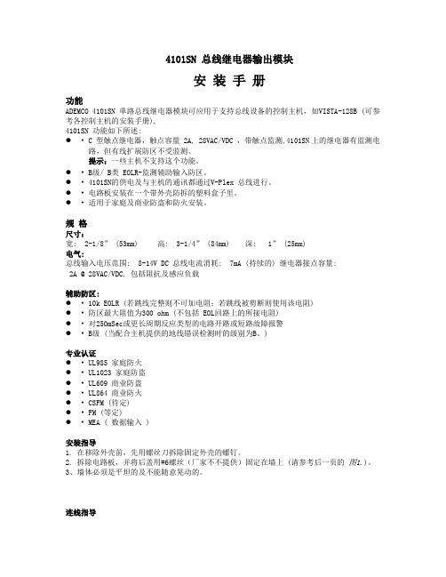
4101SN 总线继电器输出模块安装手册功能ADEMCO 4101SN 单路总线继电器模块可应用于支持总线设备的控制主机,如VISTA-128B (可参考各控制主机的安装手册).4101SN 功能如下所述:●•C 型触点继电器,触点容量 2A, 28VAC/VDC ,带触点监测,4101SN上的继电器有监测电路,但有线扩展防区不受监测。
提示:一些主机不支持这个功能。
●•B级/ B类 EOLR-监测辅助输入防区。
●•4101SN的供电及与主机的通讯都通过V-Plex 总线进行。
●•电路板安装在一个带外壳防拆的塑料盒子里。
●•适用于家庭及商业防盗和防火安装。
规格尺寸:宽: 2-1/8” (53mm) 高: 3-1/4” (84mm) 深: 1” (25mm)电气:总线输入电压范围: 8-14V DC 总线电流消耗: 7mA (持续的) 继电器接点容量:2A @ 28VAC/VDC, 包括阻抗及感应负载辅助防区:●•10k EOLR (若跳线完整则不可加电阻;若跳线被剪断则使用该电阻)●•防区最大阻值为300 ohm (不包括 EOL回路上的所接电阻)●•对250mSec或更长周期反应类型的电路开路或短路故障报警●•B级 (当配合主机提供的地线错误检测时的级别为B。
)专业认证●•UL985 家庭防火●•UL1023 家庭防盗●•UL609 商业防盗●•UL864 商业防火●•CSFM (待定)●•FM (等定)●•MEA ( 数据输入 )安装指导1. 在移除外壳前,先用螺丝刀拆除固定外壳的螺钉。
2. 拆除电路板,并将后盖用#6螺丝(厂家不不提供)固定在墙上 (请参考后一页的图1.)。
3、墙体必须是平坦的及不能随意晃动的。
连线指导1. 通过后壳上的进线孔将线材引入,并预留适当长度。
2. 将线材去外皮外,再将色线去皮适当长度,并按图1所示进行连接。
当你不剪断白色跳线时,用于辅助防区的10k EOLR 是内置的,此时只能使用N.O. 设备, 并且这些设备与4101SN 的距离不能超过3英尺(约1米)。
单路继电器模块使用说明书

1路5V继电器模块1、同一模块通过不同的接线可实现高电或低电平触发,触发电流不小于1mA,部分51单片机IO口输出能力较弱,需要上拉或者增加驱动能力电路(默认为低电平触发)。
2、低电平驱动的优点,系统加电复位时,负载不会工作,安全性较高。
3、控制电压:3VDC~12VDC(默认为5V控制),光耦隔离,可实现控制电压与驱动电压分离,实现双电源供电,提高搞干扰能力;4、被控电压:最高250VAC、30VDC;5、每组继电器有常开、常闭触点各一组,最大允许10A/250VAC;6、带LED继电器状态指示灯(继电器闭合是点亮、断开时熄灭);7、控制端和被控端都采用最新的端子接线柱设计,更实用;8、带反向续流二极管,保护继电器,延长使用寿命;9、适用场合:小家电控制、单片机开发扩展;10、双面板设计,关键线路宽线连接,保证10A电流在板上安全通过;11、输出采用大电流接线端子,方便接线且不需焊接;12、被控端覆铜堆锡,增加驱动电流;13、板子上设置有4个3mm螺丝孔,方便用户固定;14:板子尺寸:长*宽=6.5cm*2.8cm;接线说明:单路继电器板接线说明如下图所示,单路继电器板具有抗干扰性强,使用灵活,接线方便的性点。
多级隔离,即光耦隔离,继电器隔离,继电器背面引线加粗堆锡,增大了负载电流承受能力,板中增加了隔离槽。
双电源供电是指用户把控制系统的供电系统与继电器驱动电源的供电分开,独立供电。
双电源供电能够提高继电器板的抗干扰性。
低电平有效的接线图如下:双电源供电,低电平继电器导通,负载接在常开端。
高电平有效的接线图如下:双电源供电,高电平继电器导通,负载接在常开端。
南京汉盟电子提供1路、2路、4路、8路、16路、32路系列继电器模块。
德力西 CDV18-1单相电压继电器说明书

二、结构特征与工作原理围为85%-110%额定电压;在无严重震动和爆炸危险的介质中,且介质中无足以腐蚀金属和破坏绝缘的气体与尘埃;在雨雪侵袭不到的地方。
1.3.2 垂直或水平35mm 卡轨安装安装。
1.1 适用范围CDV18-1单相电压继电器(以下简称继电器),适用于交流45Hz ~65Hz ,单相AC220V 电力系统中,作为电力线路的过压、欠压保护。
---主要用于电气设备或压缩机的过压、欠压保护。
---紧急/后备电源的切换控制。
执行标准:GB/T 14048.51.2 型号定义一、概 述3.1 额定绝缘电压Ui:600V3.2 额定冲击耐受电压Uimp:AC2.5kV3.3 额定电源电压:DC12V 、AC/DC24V ~48V 、AC/DC100V ~ 240V 、A C220V3.4 延时时间:0.1s ~10s3.5 保护功能:过压保护、欠压保护3.6 使用类别下各个额定工作电压Ue/额定工作电流Ie:三、技术参数电压变换器整流稳压LED 指示输出继电器MCU 单片机旋钮电位器设定工作原理方框图AC-15:Ue/Ie:AC240V/3A, AC380V/1.9A; DC-13:Ue/Ie:DC250V/1.1A, DC125V/2.2A;3.7 约定发热电流Ith :10A3.8 触点容量:AC250V 16A ;(阻性);3.9 污染等级:33.10 电压测量误差:≤1%;3.11 设定精度:≤10%;3.12 温度波动误差:0.05%/?at=20?(0.05%?,at=68?)3.13 机械寿命:≥100万次;3.14 电寿命:≥10万次;3.15 与短路保护器(SCPD )的协调配合:推荐使用SCPD 为RT16-00,10A 的熔断器,基本保护类型“1”型协调配合,即继电器在短路条件下不应对人及设备引起危害,在未修理或更换零件前,不允许继续使用。
在选用不同型号规格的熔断器保护器时,原有的协调配合可能失效。
BR25继电器使用说明书

使用说明书铁路应用-BR255CNR700012目录目录安全 (3)产品描述 (3)安装 (3)电气连接 (4)运行和维护 (4)技术参数 (5)附录图纸A (6)2安全安全指南确保安装和操作继电器的人员:•技术上合格和胜任•完全遵守装配指导不当操作或误用可能导致以下危险:•生命危险•损害继电器和其它设备•损害继电器的功能打开设备将会使保修失效。
本手册中强调安全说明的重要信息有以下三种情形:设备操作安全电气安装应遵守相关的国家安全规定。
为确保设备安全运行,必须强制接地。
产品描述继电器用于铁路应用。
铁路应用 BR25BR25继电器位于变压器油箱及其储油柜之间的管道中,在变压器正常运行期间,它充满油。
当变压器中产生气体时,气体向储油柜上升,并聚集在继电器的上部腔室中。
油位下降,上部浮子触发报警开关。
此外,当油从变压器油箱流向储油柜时,继电器会工作。
如果发生这种情况,油流挡板会带动磁铁支撑使开关发生跳闸。
安装装配将继电器安装在从有载分接开关油箱到储油柜的管道中,水平位置,测试按钮朝上。
继电器上的红色箭头必须指向储油柜。
管道公称直径至少为25mm。
继电器应有防振动能。
在继电器和管道法兰之间,安装平面垫(请注意,此装置不包括平面垫)。
在继电器和储油柜之间提供截止阀。
拧下机械顶杆盖帽(图 1/A),然后按照下图的红色箭头缓慢推动顶杆(图 1/B)。
这样会使浮球运动,进而触发开关动作。
当测试杆推到一半时,轻瓦斯报警,当测试杆推到底时,重瓦斯动作。
松开机械测试杆后,测试杆会自动回到原来的位置。
验证完成后,安装并拧紧盖帽。
34技术参数表1基本参数外形尺寸 见附录A材质 所有外部部件都能抵抗变压器油、盐雾和紫外线 颜色 RAL7032 (标准配置)环境温度 -40~80°C 油温 -40~115 °C防护等级 IP65 符合EN60529标准重量~3 Kg油流速度 (油温20°C1.50 ± 0.20 m/s开关电气参数 (根据EN50126-1/2)开断和关合容量电压电流开断容量24 V DC ~220 V DC 2 A 动作1000次250 W L/R<40 ms 230 V AC2 A 动作1000次400 VAcosФ>0.5开关间的介电强度 1min短时工频耐受电压kV r.m.s– kV (r.m.s.)雷电冲击耐受电压 kV (peak)接点对地间24接点间(开断状态)13铁路应用 BR255附录A - 图纸下图中给出了BR25型继电器的外部尺寸:图 46CONTENT INDEX Content indexSafety (3)Product description (3)Installation (3)Electrical connection (4)Operation and maintenance (4)Technical features (5)Appendix A - Drawings (6)2SafetyProduct descriptionInstallationSafety instructionsMake sure that any person installing, taking into operation and operating the Buchholz relay:• Is technically qualified and competent.• Fully comply with these assembling instructions.Improper operations or misuse could cause danger to:• life and limb.• to the equipment and other assets of the operator.• to the equipment proper function.Opening of the device will void your warranty.Safety instructions in this manual are shown in three diffe -rent forms to emphasize important information.Safety notes on the equipment operationElectrical installation is subject to the relevant national safety rules.It is mandatory to connect the grounding cable because of safety reason.The relay Buchholz relay is used for railway application.The BR 25 relay is located in the pipework between the transformer and its conservator; during normal tran -sformer operation it is filled with oil .When the gas is generated in the transformer, it rises towards the conservator and collects in the upper cham -ber of the relay.The oil level goes down and the upper float activates the alarm switch.Moreover this relay operates in case of abnormal oil flow from the transformer tank to the conservator. If it happens the flow vent moves the support of magnets that switches the trip reeds.AssemblyMechanical testUnscrew the plug (Fig.1/A) then slowly push the button (Fig.1/B) following the red arrow as per figure below. In this way the floats moved and the switches activate.The button, after been quickly released (without accom -pany it), automatically comes back to original position. Once the verification has been completed, fit and tighten the cap nut. This test does not give the conformity of the electrical scheme.BR 25 FOR RAILWAY APPLICATIONInstall the relay in the pipe that goes from the on-load tap-changer tank to oil conservator, in an horizontal posi -tion and with the test button upwards.The red arrow on the relay must point towards the con -servator.Use a pipe diameter of at least 25 mm nominal diameter. The relay should protected against vibrations. Between the relay and the pipe flanges, install the plane gasket (please note that is not included with the device).Provide a stop valve between the relay and the conservator.34Technical featuresTable 1General data Overall dimension See page 19Material All the external part are resistant to transformer oils, salt fog and UV rays ColorRAL7032 (standard)Ambient temperature -40÷80°C Oil temperature -40÷115 °CDegree of protection IP65 in accordance with EN60529Weight~3 KgOil flow speed (oil temperature 20°C1.50 ± 0.20 m/sSwitch electrical data (according to EN50126-1/2)Breaking and making capacityVoltageCurrentBreaking capacity 24 V DC ÷ 220 V DC 2 A for 1000 maneuvers 250 W L/R<40 ms 230 V AC2 A for 1000 maneuvers400 VAcosФ>0.5Dielectric strength of contacts Short duration power frequency withstand voltage 1 min – kV (r.m.s.)Lightning impulse withstand voltage kV (peak)Between circuits and earth24Between contacts in open positions13BR 25 FOR RAILWAY APPLICATION5Appendix A - DrawingsIn the figure 1 there are the external dimensions for the relay type Buchholz relay:Figure 46CN:本安装手册包含用户安装产品所需的基本信息。
继电器使用指南

继电器使用指南(总9页) -CAL-FENGHAI.-(YICAI)-Company One1-CAL-本页仅作为文档封面,使用请直接删除Relay terms and wizard继电器的使用通常人们所说的产品可靠性是指产品的工作可靠性,其被定义:在规定的条件下和规定的时间内,完成规定功能的能力。
它由产品的固有可靠性和使用性组成,前项由产品的设计和制造工艺决定,而后者则与用户的正确使用及生产厂家售前、售后服务有关。
用户使用时应注意以下各项1、线圈使用电压2、线圈使用电压在设计上最好按额定电压选择,若不能,可参考温升曲线选择。
使用任何小于额定工作电压的线圈电压,将会继续影响继电器工作,注意线圈工作电压是指加到线圈引出端之间的电压,特别是用放大电路来激励线圈,务必保证线圈两个引出端的电压值,反之超过最高额定工作电压时也会影响产品性能,过高的工作电压会使线圈温升过高,特别是在高温下,温升过高会使绝缘材料受到损伤,也会影响到继电器的工作安全,对磁保持继电器,激励(或复归)脉宽不小于吸合(或复归)时间的3倍,否则产品会处于中位状态。
用固态器件来激励线圈时,其器件耐压至少在80V以上,且漏电流要足够小,以确保继电器的释放。
3、瞬态抑制4、继电器线圈断电瞬间,线圈上可产生高于线圈额定工作电压值30倍以上的反峰电压,对电子线路有极大的危害,通常采用并联瞬态抑制(又叫削峰)二极管或电阻的方法加以抑制,使反峰电压不超过50V,但并联二极管会延长继电器的释放时间3-5倍,当释放时间要求高时,可在二极管一端接一个合适的电阻。
5、多个继电器的并联和串联供电6、多个继电器并联供电时,反峰电压高(即电感大)的继电器会向反峰电压低的继电器放电,其释放时间会延长,因此最好每个继电器分别控制后再并联才能消除相互影响,不同线圈电阻和功耗的继电器不要串联供电使用,否则串联回路中线圈电流大的继电器不能可靠工作,只有同规格型号的继电器可以串联供电,但反峰电压会提高,应予以抑制,可以按分压比串联电阻来承受供电电压亮出继电器的线圈额定电压的那部分电压。
(完整word版)继电器使用说明
第一节继电器原理知识一、继电器的定义继电器是一种当输入量(电、磁、声、光、热)达到一定值时,输出量将发生跳跃式变化的自动控制器件。
继电器是具有隔离功能的自动开关元件,广泛应用于遥控、遥测、通讯、自动控制、机电一体化及电力电子设备中,是最重要的控制元件之一。
....继电器一般都有能反映一定输入变量(如电流、电压、功率、阻抗、频率、温度、压力、速度、光等)的感应机构(输入部分);有能对被控电路实现“通”、“断”控制的执行机构(输出部分);在继电器的输入部分和输出部分之间,还有对输入量进行耦合隔离,功能处理和对输出部分进行驱动的中间机构(驱动部分)。
....作为控制元件,概括起来,继电器有如下几种作用:.....1) 扩大控制范围。
例如,多触点继电器控制信号达到某一定值时,可以按触点组的不同形式,同时换接、开断、接通多路电路。
.....2) 放大。
例如,灵敏型继电器、中间继电器等,用一个很微小的控制量,可以控制很大功率的电路。
.....3) 综合信号。
例如,当多个控制信号按规定的形式输入多绕组继电器时,经过比较综合,达到预定的控制效果。
.... 4) 自动、遥控、监测。
例如,自动装置上的继电器与其他电器一起,可以组成程序控制线路,从而实现自动化运行。
二、继电器的工作原理如图所示,当控制电路中的开关K闭合时,电磁铁便具有磁性,将衔铁吸下,使继电器触点接触,与触点相连接的电源电路便接通;当控制开关K断开时,电磁铁的磁性被撤消,继电器触点弹开,电源电路亦随之断开。
三、继电器的继电特性继电器的输入信号x从零连续增加达到衔铁开始吸合时的动作值x x,继电器的输出信号立刻从y=0跳跃到y=y m,即常开触点从断到通。
一旦触点闭合,输入量x继续增大,输出信号y将不再起变化。
当输入量x从某一大于x x值下降到x f,继电器开始释放,常开触点断开(如图1)。
我们把继电器的这种特性叫做继电特性,也叫继电器的输入-输出特性。
- 1、下载文档前请自行甄别文档内容的完整性,平台不提供额外的编辑、内容补充、找答案等附加服务。
- 2、"仅部分预览"的文档,不可在线预览部分如存在完整性等问题,可反馈申请退款(可完整预览的文档不适用该条件!)。
- 3、如文档侵犯您的权益,请联系客服反馈,我们会尽快为您处理(人工客服工作时间:9:00-18:30)。
一模块说明:
1、模块采用正品优质继电器,常开接口最大负载:交流250V/10A,直流30V/10A;
2、采用贴片光耦隔离,驱动能力强,性能稳定;触发电流5mA;
3、模块工作电压有5V、9、12V、24V,都可以接受订货,货期请与客服联系;
4、模块可以通过跳线设置高电平或低电平触发;
5、容错设计,即使控制线断,继电器也不会动作;
6、电源指示灯(绿色),继电器状态指示灯(红色)
7、接口设计人性化,所有接口均可通过接线端子直接连线引出,非常方便
8、模块尺寸:50mm * 26mm* 18.5mm(长*宽*高)
9、设有4个固定螺栓孔,孔3.1mm,间距
44.5mm*20.5mm
二模块接口:
1、DC+:接电源正极(电压按继电器要求,有
5V.9V.12V和24V选择)
2、DC-:接电源负极
3、IN:可以高或低电平控制继电器吸合
继电器输出端:
1、NO:继电器常开接口,继电器吸合前悬空,吸合后与COM短接
2、COM:继电器公用接口
3、NC:继电器常闭接口,继电器吸合前与COM 短接,吸合后悬空
高低电平触发选择端:
1.跳线与LOW短接时为低电平触发;
2.跳线与high短接时为高电平触发。
接线可参考下面接线图:。