贴片采样电阻
取样电阻的温度影响精度测试分析
毫欧电阻的温度影响精度测试分析取样电阻的温度影响精度测试分析分流器的精确测试分析分流器是测量直流电流用的,根据直流电流通过阻值很小的电阻时在电阻两端产生电压的原理制成。
在实际应用中,要测量一个很大的电流值,没有大量程的电流表测量其电流,分流器就可以产生作用了。
分流器两端产生毫伏级直流电压信号,使并接在该分流器两端的计量表显示电压值,分流器的电阻时定值,通过计算得到实际测量的电流值。
但实际生产上,分流器并不是那么精确地电阻值,而且在不同温度条件下,其阻值也相应的发生微小的变化。
那么怎么选择最精确地分流器呢?也只能通过测试来证明所买到的分流器是否准确了。
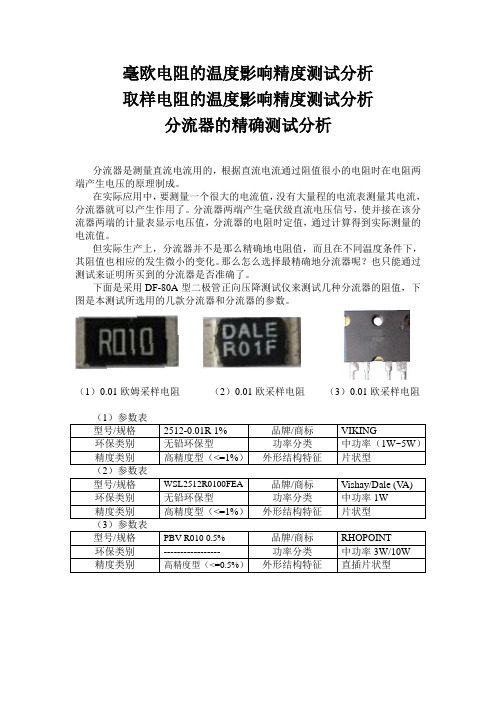
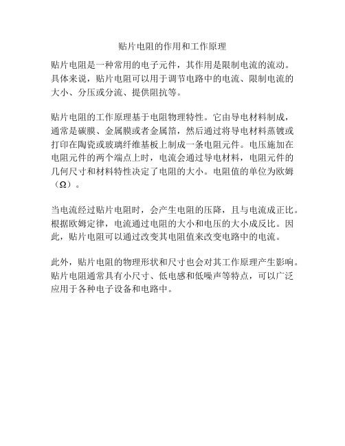
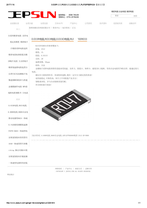
下面是采用DF-80A型二极管正向压降测试仪来测试几种分流器的阻值,下图是本测试所选用的几款分流器和分流器的参数。
(1)0.01欧姆采样电阻(2)0.01欧采样电阻(3)0.01欧采样电阻(1)参数表型号/规格2512-0.01R 1% 品牌/商标VIKING环保类别无铅环保型功率分类中功率(1W~5W)精度类别高精度型(<=1%)外形结构特征片状型(2)参数表型号/规格WSL2512R0100FEA品牌/商标Vishay/Dale (V A) 环保类别无铅环保型功率分类中功率1W精度类别高精度型(<=1%)外形结构特征片状型(3)参数表型号/规格PBV R010 0.5%品牌/商标RHOPOINT环保类别----------------- 功率分类中功率3W/10W 精度类别高精度型(<=0.5%)外形结构特征直插片状型测试连接方法在不同温度下,测试分流器的阻值稳定性。
如下图连接图所示,用电脑连接DF-80A,DF-80A连接标准分流器两端,用TEC-10B控制分流器温度。
温度设定为常温28.4℃,45℃。
测试软件截图2512-0.01R 1%的连续测试曲线WSL2512R0100FEA的连续测试曲线\PBV R010 0.5%的连续测试曲线测试的室内温度为28.4℃下,测试2512-0.01R 1%的分流器的VI数据表格电流(A) - VCE-IC曲线电压(V) - VCE-IC曲线R=U/I(欧)0 0 01 0.008 0.0082 0.018 0.0093.1 0.03 0.0096774194.1 0.039 0.0095121955.2 0.047 0.0090384626.2 0.059 0.0095161297.3 0.074 0.0101369868.3 0.079 0.0095180729.4 0.086 0.00914893610.4 0.098 0.00942307711.5 0.114 0.00991304312.5 0.12 0.009613.6 0.135 0.00992647114.6 0.142 0.00972602715.7 0.156 0.00993630616.7 0.167 0.0117.8 0.175 0.00983146118.8 0.185 0.00984042619.9 0.194 0.00974874420.9 0.207 0.00990430622 0.219 0.009954545 得到的电阻值计算平均值为0.009588欧姆。
贴片电阻的作用和工作原理
贴片电阻的作用和工作原理
贴片电阻是一种常用的电子元件,其作用是限制电流的流动。
具体来说,贴片电阻可以用于调节电路中的电流、限制电流的大小、分压或分流、提供阻抗等。
贴片电阻的工作原理基于电阻物理特性。
它由导电材料制成,通常是碳膜、金属膜或者金属箔,然后通过将导电材料蒸镀或打印在陶瓷或玻璃纤维基板上制成一条电阻元件。
电压施加在电阻元件的两个端点上时,电流会通过导电材料,电阻元件的几何尺寸和材料特性决定了电阻的大小。
电阻值的单位为欧姆(Ω)。
当电流经过贴片电阻时,会产生电阻的压降,且与电流成正比。
根据欧姆定律,电流通过电阻的大小和电压的大小成反比。
因此,贴片电阻可以通过改变其电阻值来改变电路中的电流。
此外,贴片电阻的物理形状和尺寸也会对其工作原理产生影响。
贴片电阻通常具有小尺寸、低电感和低噪声等特点,可以广泛应用于各种电子设备和电路中。
0.033R电阻,R033电阻RLP25FEER033
2017/1/160.033R 电阻,R033电阻,0.033Ω电阻,RLP25FEER033【捷比信】/gongsinews/zonghezixun/329.html 1/1深圳市捷比信科技有限公司 > 资讯中心 > 综合资讯 > 正文RLP25FEER033具体参数如下:封装:2512精度:1%阻值:0.033Ω功率:2W 温漂系数:50ppm 材质:合金金属贴片采样电阻的特性是能承受高温,功率大,阻值小,体积小。
能低至0.2毫欧,有的合金电阻有7W的功率,能通过很大电流。
捷比信大量现货库存,欢迎您的选购,我们一定尽全力满足您的需求! 电性能稳定,可靠性高;同尺寸不同阻值产品齐全!装配成本低,并与自动装贴设备匹配;符合ROHS指令要求![综合资讯] 0.009R电阻,R009合金电阻,LRP12FTWSR009现货 2512-2W-R009网络资质|产品中心|联系方式|品牌合作COPYRIGHT © ALL RIGHTS RESERVED.网站统计热门全系列精密电阻 功率电高稳定高精度 精密贴片贴片精密采样电阻选用精密电阻标准阻值及精2W贴片电阻 大功率贴片精密低温漂电阻选型方台湾VIKING高频贴片电慢速熔断保险丝与快速金属膜插件电阻 MFR系毫欧电阻规格书 大电流最新0.033R电阻,R033电阻,0.009R电阻,R009合金电移动电源用0624一体成0.1%高精度薄膜低温漂PSPFE-0603一体成型电自恢复保险丝常用型号1040一体成型型号参数viking 推出可做0Ω阻自恢复保险丝在镇流器一体成型电感常用封装0.033R电阻,R033电阻,0.033Ω电阻,RLP25FEER033精密电阻 合金电阻 毫欧电阻搜索搜索走进捷比信台湾大毅台湾光颉日本ALPS 产品中心公司资讯技术资料投资者关系战略合作。
贴片电阻识别方法

贴片电阻识别方法贴片电阻(Chip resistor)是一种非常常见的电子元器件,它主要用于电路板上的电阻器组件。
在大规模生产中,贴片电阻的精确识别和分类是非常重要的,以确保电路板的正确组装和维修。
本文将介绍贴片电阻的常见识别方法。
1.标记编码法:贴片电阻通常会在其体表上打印有识别码,以标示其阻值和额定功率。
常见的标记编码法有颜色编码法和数字编码法。
-颜色编码法:颜色编码法是最常见的贴片电阻识别方法之一、贴片电阻的体表会使用一系列不同颜色的带子来表示其阻值。
具体来说,四个彩色带子用于表示贴片电阻的阻值,第一个和第二个带子表示前两个有效数字,第三个带子表示乘以的数量级,第四个带子表示电阻器的误差。
一个例子是:黄-紫-红-金,代表阻值为4.7千欧姆,误差为5%的贴片电阻。
这种方法便于人类阅读和识别。
-数字编码法:数字编码法是另一种常见的贴片电阻识别方法。
贴片电阻的体表上会标有一个三位数的数字编码,用于表示其阻值和精度。
具体来说,前两位数字表示前两个有效数字,而第三位数字表示乘以的数量级,可以通过参考表格将这些数字转换为对应的阻值。
例如,如果数字编码为473,那么阻值为47千欧姆,误差为0.1%的贴片电阻。
2.使用测量仪器:另一种常见的贴片电阻识别方法是使用测量仪器,如万用表或LCR表。
这些仪器可以直接测量贴片电阻的阻值,并在显示屏上显示结果。
通过在测量前选择适当的量程范围,并将测试引线正确接触到贴片电阻的两个引脚上,可以准确地读取贴片电阻的阻值。
3.反射光谱法:反射光谱法是一种用于自动识别贴片电阻的高级方法。
它使用一台光学设备,通过照射贴片电阻并分析其反射光谱来确定其阻值。
这种方法可以自动快速地识别大量的贴片电阻,以提高工作效率和准确性。
4.取样和测试法:当无法通过上述方法准确识别贴片电阻时,可以从供应商处取样,并使用专业的测试设备进行详细测试。
这种方法可以通过测量和分析贴片电阻的电特性(如电流-电压特性和温度特性)来确定其阻值以及其他重要参数。
贴片电阻用途
贴片电阻用途
贴片电阻是一种小型化的电阻器,广泛应用于计算机、手机、电子辞典、医疗电子产品、摄录机、电子电度表及VCD机等电子产品中。
贴片电阻的主要用途包括:
1. 限流:为了使通过电器的电流不超过实际工作所需的额定值或规定值,以确保电器正常工作,通常可以在其中连接一个可变电阻器串联在电路中。
当电阻大小改变时,电流也改变。
这种可以限制电流的电阻称为限流电阻。
2. 分流:当需要将几个具有不同额定电流的负载同时连接到主电路时,可以在额定电流较低的负载的两端并联一个电阻,该电阻的功能是分流。
3. 分压:通常,电器上标有额定电压。
如果电源高于电器的额定电压,则不允许将电器直接连接到电源。
在这种情况下,电器可以与具有适当电阻值的电阻器串联连接以共享部分电压,使电器可以在额定电压下工作。
这种电阻被称为分压电阻。
此外,贴片电阻还具有体积小、重量轻、安装密度高、抗震性强、抗干扰能力强、高频特性好等优点,可以大大节约电路空间成本,使设计更精细化。
采样贴片电阻
采样贴片电阻贴片电阻是一种常见的电子元器件,广泛应用于电子设备中。
它具有小巧、便于安装和高精度等特点,因此在电子制造领域被广泛采用。
本文将介绍采样贴片电阻的相关知识和应用。
我们来了解一下什么是贴片电阻。
贴片电阻是一种表面贴装技术(SMT)元件,其外形呈矩形,通常由陶瓷或有机材料制成。
它的两端具有金属电极,可以通过焊接或贴片技术固定在印刷电路板(PCB)上。
贴片电阻的阻值范围很广,可以从几个欧姆到几兆欧姆不等。
此外,贴片电阻还有不同的尺寸和功率等级可供选择。
采样贴片电阻是指在电子产品的制造过程中,为了质量控制和检测而使用的贴片电阻。
采样贴片电阻的作用是通过测量其阻值来验证电路板的质量和性能。
在电子制造过程中,采样贴片电阻通常会在不同的环节进行使用,例如在贴片过程前、焊接过程中、以及成品测试中。
采样贴片电阻的选择应根据具体的需求来确定。
首先要考虑的是阻值范围,根据电路设计的需求选择合适的阻值范围。
其次是功率等级,需要根据电路的功率需求选择合适的功率等级,以确保贴片电阻在工作过程中不会过热或损坏。
此外,还需要考虑贴片电阻的尺寸和精度等级,以适应不同的应用场景。
在采样贴片电阻的应用中,常见的问题是如何进行准确的测量。
首先要选择合适的测量设备,例如万用表或自动测试设备(ATE),并确保其精度和准确性。
其次,要注意采样贴片电阻的引线接触是否良好,避免接触不良导致测量结果不准确。
此外,还要注意测试环境的温度和湿度等因素对测量结果的影响。
采样贴片电阻的质量控制是电子制造过程中非常重要的一环。
通过对采样贴片电阻的测量和分析,可以及时发现和解决电路板的质量问题,提高产品的可靠性和稳定性。
在贴片过程中,要确保贴片电阻的正确位置和方向,避免因安装错误导致的质量问题。
在焊接过程中,要控制好焊接温度和时间,以避免贴片电阻的损坏或焊接不牢固。
在成品测试中,要对采样贴片电阻的阻值进行检测,并与设计要求进行比较,以确保产品符合规格要求。
小阻值大功率贴片电阻合金采样电阻
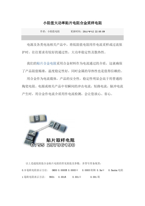
小阻值大功率贴片电阻合金采样电阻作者:小阻值电阻更新时间:2011-6-12 22:03:59电源及各类电池相关产品中,将低阻值电阻用作电流采样或过流保护时,往往要求有较好的通过性,大功率稳定性及散热性。
我们的贴片合金电阻采用合金材料作为电流通过的介质,这就确保了产品阻值精准,温度稳定性好,同时金属的导热性也是值得信赖的。
用合金作为电流载体,产品的安全性,稳定性明显会高于用普通的陶瓷电阻。
电源或相关产品中有瞬间的冲击电流,短路电流,脉冲电流产生时,用合金作电流介质用作电流检测,会让您放心、省心。
以上是超低阻值合金贴片电阻的常见阻值及参数,多型号常备现货:0.5毫欧电阻表示方法: 0M50 0.0005R 0.0005Ω 0.0005欧姆 0.5mΩ 0.5mohm电阻1毫欧电阻表示方法: R001 0.001R 0.001Ω 0.001欧姆 1mΩ 1mohm电阻2毫欧电阻表示方法: R002 0.002R 0.002Ω 0.002欧姆 2mΩ 2mohm电阻3毫欧电阻表示方法: R003 0.003R 0.003Ω 0.003欧姆 3mΩ 3mohm电阻5毫欧电阻表示方法: R005 0.005R 0.005Ω 0.005欧姆 5mΩ 5mohm电阻8毫欧电阻表示方法: R008 0.008R 0.008Ω 0.008欧姆 8mΩ 8mohm电阻10毫欧电阻表示方法: R010 0.010R 0.010Ω 0.010欧姆 10mΩ 10mohm电阻12毫欧电阻表示方法: R012 0.012R 0.012Ω 0.012欧姆 12mΩ 12mohm电阻15毫欧电阻表示方法: R015 0.015R 0.015Ω 0.015欧姆 15mΩ 15mohm电阻16毫欧电阻表示方法: R016 0.016R 0.016Ω 0.016欧姆 16mΩ 16mohm电阻20毫欧电阻表示方法: R020 0.020R 0.020Ω 0.020欧姆 20mΩ 20mohm电阻22毫欧电阻表示方法: R022 0.022R 0.022Ω 0.022欧姆 22mΩ 22mohm电阻24毫欧电阻表示方法: R024 0.024R 0.024Ω 0.024欧姆 24mΩ 24mohm电阻25毫欧电阻表示方法: R025 0.025R 0.025Ω 0.025欧姆 25mΩ 25mohm电阻27毫欧电阻表示方法: R027 0.027R 0.027Ω 0.027欧姆 27mΩ 27mohm电阻30毫欧电阻表示方法: R030 0.030R 0.030Ω 0.030欧姆 30mΩ 30mohm电阻40毫欧电阻表示方法: R040 0.040R 0.040Ω 0.040欧姆 40mΩ 40mohm电阻50毫欧电阻表示方法: R050 0.050R 0.050Ω 0.050欧姆 50mΩ 50mohm电阻60毫欧电阻表示方法: R060 0.060R 0.060Ω 0.060欧姆 60mΩ 60mohm电阻70毫欧电阻表示方法: R070 0.070R 0.070Ω 0.070欧姆 70mΩ 70mohm电阻80毫欧电阻表示方法: R080 0.080R 0.080Ω 0.080欧姆 80mΩ 80mohm电阻90毫欧电阻表示方法: R090 0.090R 0.090Ω 0.090欧姆 90mΩ 90mohm电阻100毫欧电阻表示方法: R100 0.100R 0.100Ω 0.100欧姆 100mΩ 100mohm 电阻贴片合金采样电阻封装包括 2512,1206,0805等。
采样电阻的采样原理
采样电阻的采样原理采样电阻是一种用于测量电流的电阻,其采样原理基于欧姆定律以及电阻的电流-电压关系。
在电路中,根据欧姆定律,电阻上的电压和电流之间有以下关系:V=I*R其中,V是电阻上的电压,I是通过电阻的电流,R是电阻的电阻值。
采样电阻利用该关系来测量电流。
当电流通过采样电阻时,会导致采样电阻两端产生一个电压,该电压与电流成正比。
通过测量采样电阻两端的电压,就可以得到通过采样电阻的电流。
具体来说,采样电阻连接在待测电流所经过的路径上。
当电流通过采样电阻时,在采样电阻的两端会产生一个电压。
根据欧姆定律,该电压与电流成正比,即:V=I*Rs其中,V是采样电阻两端的电压,I是待测电流,Rs是采样电阻的电阻值。
通过测量采样电阻两端的电压,可以推导出待测电流的值。
为了减小测量误差,通常采用较小的采样电阻值。
较小的采样电阻值会导致较小的电压降,从而减小测量时的电压误差。
然而,采样电阻的电阻值需要根据待测电流的大小进行选择,以确保在电流范围内满足需要的精度。
此外,采样电阻还需要具备足够的功率承受能力,以防止因过大的电流而导致采样电阻过热,甚至烧毁。
在实际应用中,为了进一步提高测量的准确性,还可以引入校准电路来对测量误差进行校正。
校准电路通常利用一个已知电流源来提供一个标准电流,通过对采样电阻两端电压的测量,并结合已知电流源提供的标准电流值,对测量结果进行校准调整。
总之,采样电阻的采样原理是基于欧姆定律和电阻的电流-电压关系。
通过测量采样电阻两端的电压,可以间接地得到通过采样电阻的电流值。
在实际应用中,根据待测电流的大小和所需的测量精度,选择合适的采样电阻值,并可引入校准电路对测量误差进行校正。
采样电阻,贴片毫欧电阻,超低阻值电阻
/xiangguaninfo/119.html
2/2
ALPS代理商: ALPS编码器 ALPS电位器 ALPS开关按键 ALPS卡座连接器 ALPS TACT Switch ALPS
/xiangguaninfo/119.html
1/2
2016/9/1
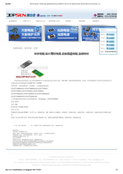
采样电阻,贴片毫欧电阻,超低阻值电阻,直销特价相关信息低阻值电阻深圳市捷比信科技有限公司
电话:075529796190
环保类别无铅环保型产品主要用途精密电子仪器仪表功率分类中功率(1W~5W)精度类别高精度型(≤1%)外形结构特征片状型引出线类型无引 出线包装形式卷带编带包装PDF资料下载PDF 采样电阻,电流检测电阻,0.2毫欧,合金超低阻值电阻 LR12FTDBR004G LR12FTDBR005G LR12FTDR001 LR12FTDR002 LR12FTDR003 LR12FTDR005 LR12FTDR020G LR12FTDRR001G LR12FTDRR002G LR12FTDRR003G LR12FTDSR010G 大功率超低阻值金属合金电流检测电阻(LR Series) LR12FTDR002 封装: 2512 ; 功率: 3W ; 阻值范围: 0.002Ω (2mΩ) ; 误差: ± 1% ; TCR温度系数:±50 PPM/℃; 各类产品,2512封装,2W , 3W功率,1%精度,5%精度,2毫欧电阻,3毫欧电阻,4毫欧电阻,5毫欧电阻及10毫欧电阻 等。 电源产品里的采样电阻,取样电阻也都有毫欧级产品,CS系列CS12FTJR010,2512封装,10毫欧电阻。
下一篇:电阻主要参数 上一篇:现货贴片电阻,2512精密贴片电阻,100毫欧电阻
随机推荐: 过流保护与短路保护介绍 锰铜、康铜、考铜是制造精密电阻、变阻器、应变片、热电偶等用的材料 高精密贴片电阻,0.01%精度电阻,万分之一精度 热敏电阻是敏感元件的一类 电阻主要参数 现货贴片电阻,2512精密贴片电阻,100毫欧电阻 插件高频无感电阻,20W电阻,50W,30W插件电阻,35W功率,TO220封装 低温度系数电阻,5ppm贴片低温漂电阻,TCR10电阻,光颉低温漂电阻 R035取样电阻0.035Ω电阻3W贴片电阻 金属膜精密电阻,金属膜精密电阻全新现货
合金贴片电阻
合金贴片电阻
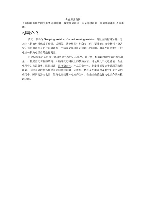
合金贴片电阻又称为电流检测电阻,电流感测电阻,合金取样电阻,电流感应电阻,合金电阻。
材料介绍
英文一般译为Sampling resistor,Current sensing resistor。
电阻主要材料为铜,再加上其他的材料就成了康铜,锰铜等。
其他辅助材料众多,但主要性能由合金材料本身决定。
通俗的讲合金贴片电阻就是一个贴片采样电阻阻值较小的电阻,串联在电路中用于把电流转换为电压信号进行测量。
合金贴片电阻采用符合高功率电气特性、高纯度、高导热、低温漂及耐高温的特殊合金,一体成型无切割的结构,大幅降低电路板上的散热面积,可达到几乎无电感值。
合金电阻作为电流载体,阻值精准,温度稳定性,产品的安全性,稳定性明显高于普通的陶瓷电阻。
同时金属的导热性也是它同其他电阻一大优势。
特别是在电源以及其它相关产品的应用中,瞬间的冲击电流,短路电流或脉冲电流产生时,合金当做首选作为电流介质来检测电流。
采样电阻
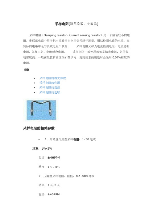
采样电阻[浏览次数:116次]采样电阻(Sampling resistor,Current sensing resistor)是一个阻值较小的电阻,串联在电路中用于把电流转换为电压信号进行测量。
用以检测电路的电流,在实际的电路中是与负载电阻串联的。
采样电阻又称为电流检测电阻,电流感测电阻,取样电阻,电流感应电阻。
采样电阻一般使用的都是精密电阻,阻值低,精密度高,一般在阻值精密度在±1%以内,更高要求的用途时会采用0.01%精度的电阻。
目录•采样电阻的相关参数•采样电阻的作用•采样电阻的连接•采样电阻的选取采样电阻的相关参数•1、高精度焊脚型采样电阻:1-50毫欧功率:1W-5W温漂:±40PPM精度:1%/5%2、压脚型采样电阻:阻值:0.1-500毫欧功率:1瓦-5瓦温漂:±40PPM精度:1%/5%3、跳线型采样电阻:阻值:0-100毫欧功率1-5W温漂:±40PPM精度10%4、大功率高精度分流电阻:0.5-5毫欧功率:8瓦-12瓦温漂:±40PPM精度:1%/5%5、大功率仿贴片电阻:阻值:1-10毫欧功率:5W-8W温漂:±40PPM精度:3%6、零阻值电阻:电流10-50A 可做成贴片或插件,尺寸形状可以定做。
采样电阻的作用•采样电阻常用在反馈电路里用以检测电路的电流,在实际的电路中是与负载电阻串联的。
以稳压电源电路为例,为使输出的电压保持恒定状态,要从输出电压取一部分电压做参考(常用取样电阻的形式),如果输出高了,输入端就自动降低电压,使输出减少;若输出低了,则输入端就自动升高电压,试输出升高。
一般使用在电源产品,或者电子,数码,机电产品的电源部分,功能强大。
采样电阻的连接•采样电阻的阻值会选在1欧姆以下,属于毫欧级电阻,但是部分电阻,有个采样电压等要求,必须选择大阻值电阻,但是这样电阻基数大,产生的误差大。
采样电阻和HCPL-7840 的连接如图采样电阻R1 的正端连接到Vin+ ,采样电阻的负端连接到Vin?,把实时的电流转化为模拟电压输入芯片;同时Vin和GND1 连接,把供电电源的返回路径又作为采样线连接到采样电阻的负端,因为电机在工作时有很大的电流流过采样线路,电路中的寄生电感会产生很大的电流尖峰,而此种连接能把这些暂态噪声视为共模信号,不会对采样电流信号形成干扰;另外,为消除采样电流输入信号中的高频噪声,采样电阻上采集到的电压信号必须经过由R2及C3组成的低通滤波器进入芯片。
贴片电阻基础知识

1 贴片电阻器的种类及特点 (1)2 贴片电阻的主要性能指标 (1)2.1标称阻值及偏差 (2)2.2额定功率: (3)2.3最大工作电压: (3)2.4、温度系数(T.C.R): (3)3 贴片电阻的结构 (3)4 贴片电阻的生产过程 (4)5 贴片电阻的选用原则 (4)6 应 用 中 常 见 问 题 (4)6.1电极脱落: (4)6.2基体断裂: (4)6.3电阻阻值变异: (5)6.4外电极氧化: (5)6.5案例分析: (5)7 0欧姆电阻的作用 (6)8 贴片电阻的标称阻值系列 (7)H (9)贴 片 电 阻 器1 贴片电阻器的种类及特点贴片电阻属于厚膜电阻,其导体是高温烧结的玻璃釉膜。
贴片电阻器的英文名称是Chip Resistor, 是应用的最成熟的表面贴装元件(SMC)之一。
按照尺寸来分类,贴片电阻有0402、0603、0805、1208、1210、2512等六种尺寸规格,各尺寸的片阻能承受的额定功率有所不同,其中0402、0603、0805是常用尺寸规格。
另外还有片状电阻网络(也称做贴片排阻)贴片电阻的特点:—体积小,重量轻,利于整机产品的小型化、微型化—温度系数小,电性能稳定,可靠性高—机械强度高,尺寸稳定,很适合SMT技术要求—高频特性优异—具有优异的适应载流焊和回流焊,很适合SMT技术要求—尺寸稳定,装配成本低并与自动贴装设备匹配好2 贴片电阻的主要性能指标贴片电阻的主要电性能指标有标称阻值及偏差、额定功率、最大工作电压;主要机械性能指标是尺寸(长L、宽W)。
贴片电阻的尺寸对所能承受额定功率起着决定性作用,其导电部分反到成了次要作用。
0402、0603、0805、1208、1210、2512这些规格是以英寸为单位的,注意与公制单位mm之间的换算关系。
2.1标称阻值及偏差贴片电阻生产过程采用激光调阻,加之其电阻膜是高稳定的玻璃釉材料,因此贴片电阻的精度比较高,最普通阻值系列的是E24系列,即±5%的偏差;另外还比较常用的E96阻值系列(即±1%的偏差),称做精密贴片电阻;也有极少数场合用到的E192系列(即±0.5%精度的);其他系列基本不采用。
贴片电阻怎么测量好坏,测量贴片电阻好坏方法

贴片电阻怎么测量好坏,测量贴片电阻好坏方法测量贴片电阻好坏的方法有很多种,但是小编建议大家采用最精准的方式测量,由于贴片电阻的体积非常小,焊接在线路板一般用肉眼也看不出什么异常,测量的话也不精准,除非是拿下来,但是烙铁头的温度很高如果反复焊接次数太多容易烧毁电阻,那么小编今天为大家介绍三种测量方法。
判断贴片电阻好坏方法第一种:用万用表在线测量法电阻值大于标称值时,说明元件有断路性故障或电阻值变大,已经损坏;所测阻值小于标称值时,要考虑到是外围并联元件对其造成的影响,应将元件一端或两端脱开电路进行测量,以便得出确切的测量结果。
一旦仪器仪表中的长方框架形线绕精密电阻损坏,可用与原电阻合金丝的材料、直径、长度均相同的新合金电阻丝均匀绕在原框架上代替。
如果原长方框架形线绕精密电阻只是表面绝缘层破损,只需将原电阻丝从框架上拆下,重新浸漆(宜选用性能优、价格低的1260绝缘清漆),再经晾干处理后重新绕到原长方框架上即可。
第二种:外观特征判断法。
具体外观特征判断如下:贴片电阻表面二次玻璃体保护膜应覆盖完好,出现脱落,可能已经损坏。
元件表面应该是平整的,若再现一些“凸凹”,可能损坏。
元件引出端电极一般应平整、无裂痕针孔、无变色现象,如果出现裂纹,则可能损坏。
贴片电阻体表面颜色烧黑,可能已经损坏。
电阻体己经变形,可能损坏。
第三种:贴片电阻器在路测量的方法。
1、观察待测电阻器。
在路检测贴片电阻器时首先将电阻器所在的电路板的供电电源断开,然后对贴片电阻器进行观察,如果有烧焦、虚焊等情况,基本可以锁定故障了。
接着根据贴片电阻的标称电阻读出电阻器的阻值。
本次测量的贴片电阻标称为103,即它的阻值为10KΩ。
2、清理待测电阻器。
如果待测电阻器比较脏,可以用刷子清理一下引脚的灰尘,有锈渍也可以用细砂纸打磨一下,否则会影响到检测结果。
3、装好表笔。
将黑表笔插进COM孔中,红表笔插进VΩ孔中。
4、调好量程。
根据贴片电阻器的标称阻值调节万用表的量程。
怎样选购贴片采样电阻
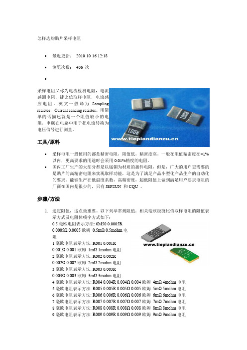
怎样选购贴片采样电阻∙最近更新:2010-10-16 12:18∙浏览次数:406 次∙采样电阻又称为电流检测电阻,电流感测电阻,捷比信取样电阻,电流感应电阻。
英文一般译为Samplingresistor,Current sensing resistor。
用简单的话描述就是一个阻值较小的电阻,串联在电路中用于把电流转换为电压信号进行测量。
工具/原料∙采样电阻一般使用的都是精密电阻,阻值低,精密度高,一般在阻值精密度在±1%以内,更高要求的用途时会采用0.01%精度的电阻。
∙国内工厂生产的大部分都是以锰铜为材质的插件电阻,但是,广大的用户更需要的是贴片的高精密电阻来实现取样功能,这是为了满足产品小型化产品生产的自动化的要求。
能够生产在低温度系数,高精密度,超低阻值上做到满足用户要求电阻的厂商在国内是很少的,只有JEPSUN 和CQU 。
步骤/方法1.选定阻值,这点最重要。
以下列举常规阻值:相关毫欧级捷比信取样电阻的阻值表示方式及电阻体喷字方式如下:0.5毫欧电阻表示方法: 0M50 0.0005R0.0005Ω 0.0005欧姆0.5mΩ 0.5mohm电阻1毫欧电阻表示方法: R001 0.001R0.001Ω 0.001欧姆1mΩ 1mohm电阻2毫欧电阻表示方法: R002 0.002R0.002Ω 0.002欧姆2mΩ 2mohm电阻3毫欧电阻表示方法: R003 0.003R0.003Ω 0.003欧姆3mΩ 3mohm电阻4毫欧电阻表示方法: R004 0.004R 0.004Ω 0.004欧姆4mΩ 4mohm电阻5毫欧电阻表示方法: R005 0.005R 0.005Ω 0.005欧姆5mΩ 5mohm电阻6毫欧电阻表示方法: R006 0.006R 0.006Ω 0.006欧姆6mΩ 6mohm电阻7毫欧电阻表示方法: R007 0.007R 0.007Ω 0.007欧姆7mΩ 7mohm电阻8毫欧电阻表示方法: R008 0.008R 0.008Ω 0.008欧姆8mΩ 8mohm电阻9毫欧电阻表示方法: R009 0.009R 0.009Ω 0.009欧姆9mΩ 9mohm电阻10毫欧电阻表示方法: R010 0.010R 0.010Ω 0.010欧姆10mΩ 10mohm电阻12毫欧电阻表示方法: R012 0.012R 0.012Ω 0.012欧姆12mΩ 12mohm电阻15毫欧电阻表示方法: R015 0.015R 0.015Ω 0.015欧姆15mΩ 15mohm电阻16毫欧电阻表示方法: R016 0.016R 0.016Ω 0.016欧姆16mΩ 16mohm电阻18毫欧电阻表示方法: R018 0.018R 0.018Ω 0.018欧姆18mΩ 18mohm电阻20毫欧电阻表示方法: R020 0.020R 0.020Ω 0.020欧姆20mΩ 20mohm电阻22毫欧电阻表示方法: R022 0.022R 0.022Ω 0.022欧姆22mΩ 22mohm电阻24毫欧电阻表示方法: R024 0.024R 0.024Ω 0.024欧姆24mΩ 24mohm电阻25毫欧电阻表示方法: R025 0.025R 0.025Ω 0.025欧姆25mΩ 25mohm电阻27毫欧电阻表示方法: R027 0.027R 0.027Ω 0.027欧姆27mΩ 27mo hm电阻28毫欧电阻表示方法: R028 0.028R 0.028Ω 0.028欧姆28mΩ 28mohm电阻2.到此可以类推了,如100毫欧捷比信电阻表示为R100,0.1R,0.1Ω,0.1欧姆,100 mΩ,100mohm等。
贴片采样电阻
贴片采样电阻贴片采样电阻是一种常见的电子元件,广泛应用于各种电路中。
它是一种电阻器,通过其电阻值的变化来实现对电路信号的采样。
我们来了解一下贴片采样电阻的基本结构和工作原理。
贴片采样电阻通常由金属薄膜材料制成,具有一个长方形的外形,两端有金属引线用于连接电路。
它的电阻值可以根据具体的应用需求进行选择,常见的有几欧姆到几千欧姆的范围。
贴片采样电阻主要用于电路中对信号进行采样和测量。
在电路中,它通常被放置在需要采样的信号路径上,通过测量其两端的电压差来获取信号的大小。
贴片采样电阻具有较低的电阻值,因此可以将采样电路对被测信号的影响降到最低。
贴片采样电阻的使用具有许多优点。
首先,它体积小、重量轻,可以方便地安装在各种电子设备中。
其次,它具有较高的精度和稳定性,可以提供可靠的测量结果。
此外,贴片采样电阻还具有较低的温漂和噪声,可以减少对信号的干扰。
在实际应用中,贴片采样电阻有许多不同的用途。
首先,它可以用于测量电路中的电流和电压。
通过在电路中串联贴片采样电阻,可以测量电流大小。
而通过在电路中并联贴片采样电阻,可以测量电压大小。
其次,贴片采样电阻还可以用于电路中的功率测量。
通过测量贴片采样电阻两端的电压差和电流值,可以计算出电路中的功率消耗。
此外,贴片采样电阻还可以用于电路中的信号采样和滤波。
通过调整贴片采样电阻的阻值,可以实现对信号频率的选择性采样。
在选购和使用贴片采样电阻时,需要考虑一些关键参数。
首先是电阻值的选择,需要根据具体的应用需求确定。
其次是功率耗散能力,需要保证贴片采样电阻在工作过程中不会因为过载而损坏。
此外,还需要考虑温度系数、精度和稳定性等参数,以确保贴片采样电阻的性能符合要求。
贴片采样电阻是一种常见且重要的电子元件,具有广泛的应用。
它通过测量电压差来实现对信号的采样,具有体积小、精度高、稳定性好等优点。
在选择和使用贴片采样电阻时,需要考虑电阻值、功率耗散能力、温度系数等关键参数。
相信在未来的发展中,贴片采样电阻将继续发挥重要的作用,并为各种电子设备和电路提供高质量的信号采样和测量功能。
大毅4527贴片合金采样电阻常备料型号查询表
2017/2/8大毅4527贴片合金采样电阻常备料型号查询表【捷比信科技】/info/20141524.html 1/10624系列一体成型电感 移动电源专用模压电感苹果收购不为进军晶圆业 原厂或成MEMS 研发中心圆柱状精密电阻光颉通过AECQ200薄膜车规电阻华为离开的背后:深圳,你是要房地产还是要制造业给大脑植入芯片不是梦,硅谷已经行动了2016无人机送快递扎堆 韩拟今年实现无人机配送快递动力电池技术是在争辩中变化,发展的人机交互新突破:手臂变成触摸板浅谈待机能耗问题及其电源解决方案首页 > 行业资讯 > 大毅4527贴片合金采样电阻常备料型号查询表大毅4527贴片合金采样电阻常备料型号查询表捷比信科技整理的大毅4527贴片合金采样电阻常备料型整理如下: RLP45FEJR006 RLP45FEJR007 RLP45FEJR008 RLP45FEJR009RLP45FEJR010 RLP45FEJR012 RLP45FEJR015 RLP45FEJR016 RLP45FEJR018 RLP45FEJR020 RLP45FEJR022 RLP45FEJR025RLP45FEJR030 RLP45FEJR033 RLP45FEJR040 RLP45FEJR050.. 查货,索样请来电洽询大毅授权代理深圳市捷比信科技有限公司C: BY:陆 TIME:20170207随机推荐:知识版权所有 © 深圳市捷比信科技有限公司服务热线:+8675529796190 传真:+8675529796149 地址:深圳市龙华新区东环一路皇嘉中心A 座820822 Email :sales@电阻产品: 低温漂电阻 大毅电阻 Viking 光颉电阻 高精密低温漂电阻 采样电阻 大功率无感电阻 插件精密电阻 高频电感 汽车专用电阻 贴片保险丝 低温漂精密电阻 毫欧电阻 排阻泰艺晶振产品: 有源晶振 晶振封装 晶振频率 晶振精度 32.768K 晶振 恒温晶振 高温晶振 可编程晶振 温补晶振 压控晶振 无源晶振 贴片晶振 插件晶振 钟振 石英振荡器 晶振波形输出 SCcut 切晶振ALPS 代理产品: ALPS 编码器 ALPS 电位器 ALPS 开关按键 ALPS 卡座连接器 ALPS TACT Switch网站统计走进捷比信大毅(TA-I)光颉(Viking)阿尔卑斯(ALPS)公司简介资讯信息联系我们。
1206 10mr采样电阻
1206 10mR采样电阻是一种精密电阻,其阻值为10m Ω(即0.01Ω),尺寸为1206(长×宽×高=3.2mm×2.0mm ×1.6mm),属于微型贴片电阻的一种。
这种电阻常用于模拟/数字转换器(ADC)的采样电阻,因此被称为采样电阻。
由于其阻值较小,精度较高,因此广泛应用于高精度的测量和控制系统。
此外,由于这种电阻尺寸小巧,便于集成在微控制器、传感器和信号处理电路中,因此得到了广泛的应用。
同时,由于其价格相对较低,也使得这种电阻在市场上具有一定的竞争优势。
需要注意的是,由于这种电阻的阻值较小,精度较高,因此对于生产工艺和材料的要求也较高,否则会影响其稳定性和可靠性。
同时,使用时需要注意避免过载和高温等不利条件的影响,以保证其正常工作。
- 1、下载文档前请自行甄别文档内容的完整性,平台不提供额外的编辑、内容补充、找答案等附加服务。
- 2、"仅部分预览"的文档,不可在线预览部分如存在完整性等问题,可反馈申请退款(可完整预览的文档不适用该条件!)。
- 3、如文档侵犯您的权益,请联系客服反馈,我们会尽快为您处理(人工客服工作时间:9:00-18:30)。
27
Ultra Low Ohm (Metal Strip) Chip Resistor -LR Series
eatures
-High power rating up to 3 Watts -Low TCR down to ±50 PPM/℃
-Resistance values from 0.5 to 20 m ohm -Customized resistance available
-Wide range package sizes 1206 / 2010 / 2512
pplications
-NB (for Power Management)
-MB (for Power Management)
-SWPS (DC-DC Converter, Charger, Adaptor)
-Monitor (for Power Management)
onstruction
Black – Wave or IR reflow soldering
Green – IR reflow soldering only
art Numbering
c Product Type
LR Ultra Low Ohm Metal Strip Chip Resistor
d Dimensions (L×W)
Dimensions (L×W) EIA
LR12 6.3×3.1mm
2512 LR10 5.1×2.5mm 2010 LR06 3.2×1.6mm 1206 e Resistance Tolerance
Resistance Tolerance
J ±5% H ±3% G ±2% F ±1% f Packaging
Code Type
T Taping Reel g TCR
Type
D ±50 PPM/℃
W
±75 PPM/℃ E
±100 PPM/℃ K
±150 PPM/℃ LR 1
12 2
J 3
T 4
E 5
S 6
R0037
G 8
h Power Rating Codes Type Standard A 1.5W S 2W R 3W B 2.5W
i Resistance Codes Type 0M50 0.00050Ω 0M75 0.00075Ω 1M50 0.00150Ω R002 0.00200Ω
R020 0.02000Ω j Protective Coating Codes
Type Black Coating G Green Coating 2010/1206 No coating / marking Figure 1
Figure 2
Tel:+86-0755-******** Fax: +86-0755-******** E-mail jepsun#
28
S tandard Electrical Specifications
Operating Current I=√(P/R):Operating Voltage V=√(P*R)
H igh Power Rating Electrical Specifications
Operating Current I=√(P/R),Operating Voltage V=√(P*R)
* Viking is capable of manufacturing the optional spec based on customer’s requirement.
Tel:+86-0755-******** Fax: +86-0755-******** E-mail jepsun#
29
ackaging
a c k a g i n g Q u a n t i t y
E m b o s s P l a s t i c T a p e S p e c i f i c a t i o n s
Top Tape
1 1.4Min.
Unit: mm
Size
Resistance (m Ω) A B W E F P 0 P 1 P 2 ΦD 0 T
0.50~7 3.40±0.1 6.73±0.1 12.0±0.1 1.75±0.1 5.5±0.05 4.0±0.1 4.00±0.1 2.0±0.05 1.50±0.100.81±0.1LR12 0.50~20 3.40±0.1 6.75±0.1 12.0±0.1 1.75±0.1 5.5±0.05 4.0±0.1 4.00±0.1 2.0±0.05 1.55±0.050.80±0.1LR10 1~10 2.85±0.1 5.55±0.1 12.0±0.2 1.75±0.1 5.5±0.05 4.0±0.1 4.00±0.1 2.0±0.05 1.55±0.050.85±0.1LR06
1~10
1.90±0.1 3.60±0.1 8.0±0.2
1.75±0.1
3.5±0.05
4.0±0.1
4.00±0.1 2.0±0.05 1.55±0.050.87±0.1
Notice:
1. The cumulative tolerance of 10 sprocket hole pitch is ±0.2mm.
2. Carrier camber shall be not more than 1mm per 100mm through a length of 250mm.
3. A & B measured 0.3mm from the bottom of the packet
4. t measured at a point on the inside bottom of the packet to the top surface of the carrier.
5. Pocket position relative to sprocket hole is measured as the true position of the pocket and not the pocket hole.
E nvironmental Characteristics
Specification
Item
Black coating
Green coating
Test Method
1
Temperature Coefficient of Resistance
As Spec.
MIL-STD-202F- Method 304 +25/-55/+25/+125/+25℃
2 Thermal Shock ±0.5% ±1% MIL-STD-202F- Method 107G -55℃~150℃,100 cycles
3 Short Time Overload ±0.5% ±1% JIS-C-5202-5.5
5×rated power ,5 seconds 4
Resistance to Dry Heat
±1% ±1% JIS-C-5202-7.2
96 hours @ +170℃ without load 5 Load Life ±1% ±1% MIL-STD-202F-Method 108A
RCWV,70℃ ,1.5 hours on, 0.5 hours off, total 1000~1048 hours 6 Resistance to Soldering Heat ±0.5%
±1%
MIL-STD-202F-Method 210E 260±5℃,10±1seconds 7 Solderability
95% min coverage
MIL-STD-202F-Method 208H 245±5℃,3±0.5seconds
* Storage Temperature :25±3;℃ Humidity <80%RH
Tel:+86-0755-******** Fax: +86-0755-******** E-mail jepsun# 。