MRIX灯光控制系统软件中文说明书优选稿
自动高光灯控制系统说明书
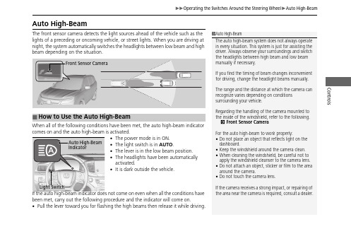
ControlsAuto High-BeamThe front sensor camera detects the light sources ahead of the vehicle such as the lights of a preceding or oncoming vehicle, or street lights. When you are driving at night, the system automatically switches the headlights between low beam and high beam depending on the situation.When all of the following conditions have been met, the auto high-beam indicator comes on and the auto high-beam is activated.•The power mode is in ON.•The light switch is in AUTO .•The lever is in the low beam position.•The headlights have been automatically activated.•It is dark outside the vehicle.If the auto high-beam indicator does not come on even when all the conditions have been met, carry out the following procedure and the indicator will come on.•Pull the lever toward you for flashing the high beams then release it while driving.1Auto High-BeamThe auto high-beam system does not always operate in every situation. This system is just for assisting the driver. Always observe your surroundings and switch the headlights between high beam and low beam manually if necessary.If you find the timing of beam changes inconvenient for driving, change the headlight beams manually.The range and the distance at which the camera can recognize varies depending on conditions surrounding your vehicle.Regarding the handling of the camera mounted to the inside of the windshield, refer to the following.2Front Sensor Camera For the auto high-beam to work properly:•Do not place an object that reflects light on the dashboard.•Keep the windshield around the camera clean.•When cleaning the windshield, be careful not to apply the windshield cleanser to the camera lens.•Do not attach an object, sticker or film to the area around the camera.•Do not touch the camera lens.If the camera receives a strong impact, or repairing of the area near the camera is required, consult a dealer.■How to Use the Auto High-BeamAuto High-BeamIndicatorLight SwitchControls ■Automatic switching between high-beam and low-beamWhen auto high-beam is active, the headlights switch between high beam and lowbeam based on the following conditions.■Manual switching between high-beam and low-beamIf you want to manually switch the headlights between high beam and low beam,follow either of the procedures below. Note that when you do this, the auto high-beam indicator will turn off and the auto high-beam will be deactivated.Using the lever:Pull the lever toward you for flashing the high beams then release it within aboutone second while driving.u To reactivate the auto high-beam, pull the lever toward you for flashing thehigh beams then release it while driving. The auto high-beam indicator willcome on.Using the light switch:Turn the light switch to .u To reactivate the auto high-beam, turn the light switch to AUTO when thelever is in the low beam position, the auto high-beam indicator will come on.Switching to high beam:Switching to low beam:All of the following conditions mustbe met before the high beams turnon.●Your vehicle speed is 45mph(72 km/h) or more.●There are no preceding oroncoming vehicle with headlightsor taillights turned on.●There are few street lights on theroad ahead.One of the following conditionsmust be met before the low beamsturn on.●Your vehicle speed is 30 mph(48 km/h) or less.●There is a preceding or oncomingvehicle with headlights ortaillights turned on.●There are many street lights onthe road ahead.1How to Use the Auto High-BeamIn the following cases, the auto high-beam systemmay not switch the headlights properly or theswitching timing may be changed. In case of theautomatic switching operation does not fit for yourdriving habits, please switch the headlights manually.•The brightness of the lights from the preceding oroncoming vehicle is intense or poor.•Visibility is poor due to the weather (rain, snow,fog, windshield frost, etc.).•Surrounding light sources, such as street lights,electric billboards and traffic lights are illuminatingthe road ahead.•The brightness level of the road ahead constantlychanges.•The road is bumpy or has many curves.•A vehicle suddenly appears in front of you, or avehicle in front of you is not in the preceding oroncoming direction.•Your vehicle is tilted with a heavy load in the rear.•A traffic sign, mirror, or other reflective objectahead is reflecting strong light toward the vehicle.•The oncoming vehicle frequently disappears underroadside trees or behind median barriers.•The preceding or oncoming vehicle is a motorcycle,bicycle, mobility scooter, or other small vehicle.The auto high-beam system keeps the headlight lowbeam when:•Windshield wipers are operating.•The camera has been detected a dense fog.ControlsYou can turn the auto high-beam system off. If you want to turn the system off or on, set the power mode to ON, then carry out the following procedures while the vehicle is stationary.To turn the system off:With the light switch is in AUTO , pull the levertoward you and hold it for at least 40 seconds. After the auto high-beam indicator light blinks twice, release the lever.To turn the system on:With the light switch is in AUTO , pull the lever toward you and hold it for at least 30 seconds. After the auto high-beam indicator light blinks once, release the lever.■How to Turn Off the Auto High-Beam1How to Use the Auto High-BeamIf the Some Driver Assist Systems CannotOperate: Camera Temperature Too High message appears:•Use the climate control system to cool down the interior and, if necessary, also use defroster mode with the airflow directed toward the camera.•Start driving the vehicle to lower the windshield temperature, which cools down the area around the camera.If the Some Driver Assist Systems CannotOperate: Clean Front Windshield or Auto High-Beam Cannot Operate: Clean Windshield message appears:•Park your vehicle in a safe place, and clean thewindshield. If the message does not disappear afteryou have cleaned the windshield and driven for a while, have your vehicle checked by a dealer.1How to Turn Off the Auto High-BeamIf you turn the auto high-beam system off, the system does not operate until you turn the system on.Park in a safe place before turning the system off or on.AUTO Position。
MicroMR磁共振成像软件说明书
目录第一章软件概述 (2)一、软件功能概述 (2)二、软件应用 (2)1、如何寻找中心频率 (2)2、如何确定所需要的硬脉冲脉宽 (4)3、如何进行电子匀场 (5)4、如何确定所需要的软脉冲幅度 (6)三、注意事项 (7)第二章软件介绍 (8)一、软件的界面 (8)二、菜单栏与工具栏 (9)1、菜单栏 (9)2、工具栏 (10)三、功能选项卡 (10)1、采样模块 (11)2、处理模块 (14)第三章脉冲序列 (16)一、硬脉冲FID序列 (16)二、软脉冲FID序列 (17)三、多层自旋回波序列 (18)四、多层梯度回波序列 (19)五、三维梯度回波序列 (21)第一章软件概述一、软件功能概述MicroMR的成像软件功能强大、设计开放、使用灵活,能够满足不同层次人群对核磁共振成像的需求,是目前低场核磁共振成像领域中最为强大的成像软件之一。
该软件提供了多种不同的脉冲序列,可以满足用户核磁成像的不同需求;预留了多路控制通道,使软件的升级更加简单;设计了可调节的脉冲宽度、脉冲幅度以及触发时间,真正的让用户来控制脉冲序列。
二、软件应用使用MicroMR的成像软件进行实验是一个操作相对复杂、顺序十分灵活的过程。
无论是仪器参数的设置还是脉冲序列的使用都需要操作者对核磁共振成像理论有着比较深入的理解。
如果您现在还只是初学者,相信下面的范例可以指导您顺利完成对MicroMR的成像软件的常用操作。
1、如何寻找中心频率MicroMR使用的磁体是永磁体,而永磁体具有固有频率。
只有在射频脉冲频率与永磁体固有频率相同的条件下,放在磁体内的样品才会发生核磁共振现象,而该固有频率就被称作共振频率,也称作中心频率。
因为磁体频率随时间的推移,可能会产生微小漂移,所以需要调整射频脉冲频率使其达到与磁体频率一致,也就是寻找中心频率,在实验中是经常会用到的,其具体步骤如下:(1) 放入标准油样,一般不含杂质的植物油即可;(2) 双击桌面上的,运行MicroMR的成像软件,打开Demo文件夹里的硬脉冲自由感应衰减(Free Induction Decay, FID)序列(File->Open->D:\MicroMR\Data\Demo\FID_V2.fid);注:Demo文件夹在安装目录的Data文件夹下面。
CRMX无线DMX控制系统用户指南说明书

against harmful interference in a residential installation. This
equipment uses and can radiate radio frequency energy and,
if not installed and used in accordance with the instructions,
a circuit different from that which the radio receiver is connected -
Consult the dealer or an experienced radio/TV technician for help.
Modifications made to the product, unless expressly approvradio or television reception, which can be
determined by turning the equipment off and on, the user is
encouraged to try to correct the interference by one or more
DI-000-WCRMX-04A.indd 1
5/11/11 11:09 AM
Rear panel connections
Single CRMX transmitter or receiver unit
12VDC power input Polarity is unimportant
5-pin XLR socket
Leviton, could void the user’s right to operate the equipment.
顾德灯光控台Victory 1 使用说明书
Victory 1灯光控制台使用说明书VVVeerer.r.1.1.11..0206.64221顾德电子有限公司CODE ELECTRONIC CO., LTD. 目录1. 控台设置.................................................................................................................................................................................1 1.1. 控台操作界面.............................................................................................................................................................1 1.1.1. 触摸屏操作界面.............................................................................................................................................1 1.1.2. 控制面板.........................................................................................................................................................3 1.1.3. 控台背面装置.................................................................................................................................................4 1.2. 清除控台全部数据.....................................................................................................................................................4 1.3. 保存和读取 Show........................................................................................................................................................52. 配接灯具.................................................................................................................................................................................6 2.1. 配接新的设备.............................................................................................................................................................6 2.1.1. 配接调光光路.................................................................................................................................................6 2.1.2. 配接电脑灯.....................................................................................................................................................7 2.2. 配接选择的类型.........................................................................................................................................................8 2.3. 删除配接.....................................................................................................................................................................8 2.4. 重新配接.....................................................................................................................................................................8 2.5. 设置 RDM 设备...........................................................................................................................................................10 2.5.1. 远程设置设备...............................................................................................................................................10 2.5.2. 匹配 RDM 设备...............................................................................................................................................11 2.6. 灯具参数设置...........................................................................................................................................................123. 手动控制灯具.......................................................................................................................................................................13 3.1. 灯位布局设置...........................................................................................................................................................14 3.2. 灯具的选择...............................................................................................................................................................15 3.3. 手动控制灯具...........................................................................................................................................................16 3.3.1. 点亮灯具.......................................................................................................................................................16 3.3.2. 修改灯具的属性值 .......................................................................................................................................16 3.3.3. 独特的通道属性调用 ...................................................................................................................................16 3.3.4. 找灯模式.......................................................................................................................................................17 3.3.5. 灯具宏功能...................................................................................................................................................17 3.3.6. 扇形模式.......................................................................................................................................................17 3.3.7. 清除手动控制...............................................................................................................................................18 3.4. 灯光设备编组和选择...............................................................................................................................................18 3.4.1. 组的编程.......................................................................................................................................................18 3.4.2. 组的管理.......................................................................................................................................................19 3.4.2.1. 设置灯具顺序...........................................................................................................................................194. 素材.......................................................................................................................................................................................20 4.1. 编辑素材数据...........................................................................................................................................................20 4.2. 素材的管理...............................................................................................................................................................21 4.3. 使用预置素材...........................................................................................................................................................225. 图形效果...............................................................................................................................................................................23 5.1. 图形效果发生器如何工作.......................................................................................................................................23 5.2. 调用图形效果...........................................................................................................................................................23 5.3. 图形参数设置...........................................................................................................................................................24 5.3.1. 图形的大小、速度和展开...........................................................................................................................24Victory 1 控台说明书5.3.2. 图形的速度组、分区组和宽度 ...................................................................................................................24 5.3.3. 图形的速度组、分区组和宽度 ...................................................................................................................24 5.3.4. 图形效果的方向...........................................................................................................................................24 5.3.5. 图形效果运行模式 .......................................................................................................................................25 5.3.6. 图形灯具顺序...............................................................................................................................................25 5.3.7. 同步...............................................................................................................................................................25 5.3.8. 图形循环运行...............................................................................................................................................25 5.3.9. 删除图形.......................................................................................................................................................25 5.4. 用户图形...................................................................................................................................................................26 5.4.1. 新建用户图形...............................................................................................................................................26 5.4.2. 保存用户图形...............................................................................................................................................27 5.4.3. 用图形命名...................................................................................................................................................27 5.4.4. 删除用户图形...............................................................................................................................................27 6. 重演程序...............................................................................................................................................................................28 6.1. 重演程序和重演页...................................................................................................................................................28 6.2. 表演程序编辑菜单...................................................................................................................................................28 6.3. Cue 程序....................................................................................................................................................................28 6.3.1. Cue 的保存模式............................................................................................................................................28 6.3.2. Cue 的运行模式............................................................................................................................................28 6.3.3. 保存 Cue 程序...............................................................................................................................................28 6.4. 多步程序...................................................................................................................................................................29 6.4.1. 创建一个多步程序 .......................................................................................................................................29 6.4.2. 多步程序的编辑...........................................................................................................................................30 6.5. 程序时间编辑...........................................................................................................................................................33 6.5.1. 设置程序全局时间 .......................................................................................................................................33 6.5.2. 设置属性时间...............................................................................................................................................34 6.5.3. 瞬变通道触发设置 .......................................................................................................................................34 6.5.4. Chase 程序的时间........................................................................................................................................35 6.5.5. Cue-lists 程序的即时时间设置................................................................................................................35 6.6. 重演程序高级设置...................................................................................................................................................35 6.6.1. 程序优先级...................................................................................................................................................35 6.6.2. 内部 LINK 模式.............................................................................................................................................36 6.6.3. 程序开始时间设置 .......................................................................................................................................36 6.6.4. 推杆效果设置...............................................................................................................................................36 6.6.5. 重演推杆页锁定...........................................................................................................................................36 6.6.6. Chase 模式....................................................................................................................................................36 6.6.7. Flash 模式....................................................................................................................................................36 6.6.8. 程序重命名...................................................................................................................................................36 6.7. 运行重演程序...........................................................................................................................................................37 6.8. 表演程序参数...........................................................................................................................................................37 6.8.1. 加载 Cue 到编辑区.......................................................................................................................................37 6.8.2. 表演程序的其他参数 ...................................................................................................................................38 7. 辅助高级功能.......................................................................................................................................................................39 7.1. 复制功能...................................................................................................................................................................39Victory 1 控台说明书7.2. 删除功能...................................................................................................................................................................39 7.3. 移动功能...................................................................................................................................................................39 7.4. 锁定控台...................................................................................................................................................................39 7.5. 命名管理...................................................................................................................................................................40 8. 宏表演的记录.......................................................................................................................................................................41 8.1. 控台的音乐播放器...................................................................................................................................................41 8.2. 记录宏表演...............................................................................................................................................................418.2.1. 编辑修改宏表演...........................................................................................................................................43 9. 控台设置...............................................................................................................................................................................459.1. 控台选项设置...........................................................................................................................................................45 9.1.1. 控台设置.......................................................................................................................................................45 9.1.2. 日期和时间设置...........................................................................................................................................46 9.1.3. MIDI 设置......................................................................................................................................................46 9.1.4. 触摸屏校对设置...........................................................................................................................................47 9.1.5. 按键背光设置...............................................................................................................................................47 9.1.6. 选择语言.......................................................................................................................................................479.2. 系统管理设置...........................................................................................................................................................47 9.2.1. 更新设置菜单...............................................................................................................................................47 9.2.2. 灯库管理.......................................................................................................................................................489.3. DMX 网络设置............................................................................................................................................................51 9.3.1. 网络设置.......................................................................................................................................................51 9.3.2. 网络设置.......................................................................................................................................................5110. 技术规格.............................................................................................................................................................................52Victory 1 控台说明书欢迎使用 Victory 1 灯光控制台为了方便用户获得更好的使用知识,本手册在重要内容部分均以带底纹加以表示。
X光源简易操作说明Rev1

X光源简易操作说明一、交流输入电源检查和保护1.检查输入电源目的提醒和建议客户在使用光机前,测量交流输入电源的漏电情况,检测供电电源环境,确保设备使用的输入电源稳定、可靠、漏电小,减小供电电源对X光机的干扰,从而保障X 光机在客户端稳定运行。
2. 不良电源的介绍• 交流输入电源没有地线或者地线接触不良。
当使用万用表测量零线和地线之间的漏电时,万用表显示0V。
正常情况下,零线和地线之间会存在较小的交流电压。
这种不良的电源环境会使光机控制部分的开关元件受到外接干扰影响。
• 输入电源被隔离(浮空)。
当使用万用表测量零线和地线之间的漏电时,万用表显示110VAC 或其它较大的电压值. 电压浮空有可能导致输入电源产生较大波动,这会使光机控制部分的开关元件受到影响• 输入电源漏电较大。
电源零线和地线之间的交流电压超过1VAC。
电源漏电较大会使光机容易受到电磁干扰。
• 光机周围存在大功率用电设备的使用,不稳定电源,受污染情况较严重的电网都会产生较大的浪涌干扰,这种浪涌干扰会通过输入电源直接影响到光机的内部信号和内部元件正常工作。
• 同一个设备使用不同的接地点,会产生较大的电磁干扰,这种干扰严重时会影响光机正常工作。
3. 输入电源的检查以下数据为正常电源环境检测数据:位置 火线-零线 零线-地线 火线-地线电压值(VAC) 220±10% <1 220±10%关键点:1. 零线和地线之间漏电小于1VAC.2.良好接地3.电源稳定4. 低干扰4. 不良输入电源的推荐解决对策• 确保输入电源有地线,并且接触良好,同时确保控制盒外壳,射线箱体外壳,操作电脑和设备系统地线都连接于一点,并连接到电源地;如若使用现场没有电源地,则需要制作接地桩,然后将控制盒外壳,射线箱体外壳,操作电脑和整套设备系统地线都连接到接地桩。
• 推荐使用隔离变压器,滤波器和压敏电阻组合电路保护光机。
请参考下一页保护电路图。
MADRIX灯光控制系统软件中文说明书

目 录1. 概述1.1分区1.2 接线1.3 启动和关闭1.4 观测器Avolites Visualiser1.5 控台模拟器The Pearl simulator1.6 准备工作2. 配置2.1 总清除2.2 配置常规灯2.3 配置摇头灯2.4 标记2.5 调节灯具的地址码2.6 重置灯具地址码2.7 辅助功能2.8 完成配置2.9 保存程序2.10 范例3. 手动控制灯具3.1 控制常规灯通道3.2 控制灯具3.3 修改灯具属性3.4 选色器3.5 使用灯具组群3.6 复制其他灯具上的设置 – Align 3.7 发散模式3.8 范例4. 素材4.1 使用素材4.2 创建素材4.3 储存素材4.4 共享素材和独立素材4.5 范例5. 图形5.1 何为图形5.2 选择图形5.3 修改图形大小和速度5.4 修改图形位置5.5 多台灯如何展示同一图形?5.6 范例6. 场景6.1 HTP和LTP通道6.2 编程时控台是如何运作的6.3 储存场景6.4 场景重放6.5 滚筒翻页6.6 标记滚筒6.7 复制场景6.8 删除场景6.9 编辑场景6.10 Include剪贴功能6.11 设置场景的转换时间6.12 灯具或通道储存6.13 调用场景中的图形6.14 范例7. 程序7.1 何为程序7.2 储存程序7.3 运行程序7.4 设置速度和交叉换场7.5 为程序取名7.6 编辑程序7.7 复制程序7.8 删除程序7.9 校时、剧本程序和场景控制7.10 音乐同步7.11 范例8. 剧场叠加8.1 设置剧本模式8.2 剧场控制8.3 编辑剧目8.4 剧目取名8.5 设置转换时间8.6 剧目转换8.7 运行9. 运行演出程序9.1 演出时间9.2 暂时锁住控台9.3 运行模式9.4 运行中手动控制9.5 主推杆9.6 通道模拟物10. 高级功能11. 与老控台的区别11.1 本机新特性11.2 转轮控制数值11.3 Preset Focuses改为素材键Palettes 11.4 “程序”包含“图形”11.5智能属性显示11.6 标记11.7 其他特性1. 概述本手册是为了让您最有效地使用我们的控制台而设计的,共分两部分。
X-ray FGUI 3.4 中文操作手册

FGUI软件操作 – 如何设置隐藏的探测器参数
鼠标右键点击该探测器图标,出现对话菜单
探测器工作模式 静态消噪功能 动态消噪功能 探测器矫正
Technology with Passion
FGUI 中文操作手册
FGUI软件操作 – 如何设置隐藏的探测器参数
确认以下列三项的设置
中质量工作模式
静态设置94%
Technology with Passion
FGUI 中文操作手册
FGUI软件操作 – 如何建立一个标准的IP
步骤1:点击Image process选项,在下拉菜单中点击新建New。
Technology with Passion
FGUI 中文操作手册
FGUI软件操作 – 如何建立一个标准的IP
Condition,长时间顺 管,用于很久没有使用 设备的情况
Technology with Passion
FGUI 中文操作手册
FGUI软件操作 – 界面介绍
X射线信息界面
靶模式选择: Transmission 标准靶 High Power 高功率靶
Technology with Passion
步骤2:在出现的对话框中,命名新建的IP程序。
Technology with Passion
FGUI 中文操作手册
FGUI软件操作 – 如何建立一个标准的IP
步骤3:点击右侧工具栏的的图标,出现模块群组,可以从中选择需要用的模块。
Technology with Passion
FGUI 中文操作手册
Technology with Passion
FGUI 中文操作手册
FGUI软件操作 – 界面介绍
•简易模式界面(通常不用) •图像处理模式界面 •机械轴信息界面 •X射线管信息界面 •矩阵编程界面
XRS-4 X光源操作手册说明书

XRS-4X-RAY SOURCEOPERATOR’S MANUALCONTENTSITEM PAGE1.0 INTRODUCTION (2)2.0 WARNINGS (2)DUTY CYCLE (2)3.0 PHYSICAL DESCRIPTION (3)HIGH VOLTAGE PULSER/TUBEHEAD (3)BASE (3)BATTERY PACK (3)BATTERY CHARGER (3)CONTROL MODULE (4)CABLE CONNE CTOR DIAGRAM (5)4.0 DESCRIPTION OF OPERATION (6)BLOCK DIAGRAM (6)5.0 OPERATING INSTRUCTIONS (7)OPERATING PRECAUTIONS (7)EXCLUSION ZONE (7)PULSE SELE CTION (7)REMOTE CABLE OPTION (8)DELAY MODE OPTION (8)REAL TIME IMAGING OPTION (8)PULSE SETTINGS (8)6.0 SOFTWARE (9)7.0 MAINTENANCE (9)DOSE MEASUREMENT (9)TUBE RE PLACEMENT (9)8.0 TROUBLE-SHOOTING (10)9.0 INSTRUCTIONS FOR REPAIR (10)FUSE REPLACEMENT (10)REMOVING BOARDS (10)BOARD INSTAL LATION (11)BATTE RY DISPOSAL (11)10.0 WARRANTY (13)RETURNING REPAIR INSTRUCTIO NS (13)11.0 SPECIFICATIONS (14)PHYSICAL DIMENSIONS (14)X-RAY OUTPUT (14)ELECTRICAL & THERMAL CHARACTERISTICS (14)12.0 SPAR E PARTS (14)1.0 INTRODUCTIONThe XRS-4 produces high levels of radiation and must be operated by qualified personnel who have read the Warning and Operations section of the manual before operating the device.The XRS-4 is a small, lightweight x-ray generator that operates on its own removable battery pack. The XRS-4 is a pulsed x-ray device that produces x-ray pulses of very short duration (50 nanoseconds). It produces a relatively low dose rate comparable to a 0.25 ma constant potential machine. The energy produced by the XRS-4 is up to 370KVP, which makes it possible to radiograph up to one (1.5) inch (3.81 cm) of steel.XRS-4 standard accessories are two keys, two battery packs, and one battery charger. Remote cable, carrying case, and film developing equipment are also common accessories.2.0 WARNINGSThe XRS-4 is a pulsed X-ray generator that emits hazardous ionizing radiation when pulsing. The XRS-4 should only be operated by authorized personnel who are properly trained to safely operate the generator. The XRS-4 must be registered with proper authorities prior to use and should not be used to intentionally expose humans.Develop and closely follow a safe operating system for using the XRS-4. The safe operating system must ensure that no one is exposed to radiation above the permissible limits which are 2 mR (0.02 mSv) per hour for a member of the public. The safe operating system must ensure the XRS-4 is used within federal and state guidelines.All operators and users of the XRS-4 x-ray machine must wear a personal radiation monitoring device, such as a TLD (thermo luminescent dosimeter), film badge, and/or a pocket dosimeter consistent with the appropriate federal, territorial or provincial standards (note: an electronic dosimeter will not detect the XRS-4 radiation pulses).Due to the short pulse width of the XRS-4, survey meters of the Geiger-Mueller and scintillator type do not accurately detect the radiation emitted from the x-ray source.Survey meters should be of the ionization type and should be used in the integration mode. Survey meters must not be used in the rate mode because the XRS-4 does not produce constant radiation. The XRS-4 produces very high rates of radiation for very short periods of time resulting in either unrealistically high readings or no readings for a survey meter in rate mode.The XRS-4 has no explosion proof rating and should not be used in an explosive atmosphere. The Spark Gap is vented to the air and could be a source of ignition.DUTY CYCLE WARNING.The XRS-4 is a light duty machine that is not made to pulse continuously. The maximum duty cycle for the XRS-4 is 200 pulses every four minutes (3000 pulses per hour). Two consecutive pulse trains of 99 pulses can be fired then the unit should rest at least four minutes. Exceeding the duty cycle will shorten the life of the tube and head.3.0 PHYSICAL DESCRIPTIONFigure 1: XRS-4 X-ray UnitHIGH VOLTAGE PULSER/TUBEHEAD. The main body of the XRS-4 is the tube head which contains the tube cavity, cold cathode type X-ray tube, spark gap, high voltage capacitor, and transformer. The standard collimator located on the front of the head limits the X-ray beam to 40 degrees. Special order collimators up to 85 degrees are available.BASE . The base of the XRS-4 contains the identification label and a threaded ¼-20 insert that can be attached to any standard camera tripod. Identification label indicates the model, manufacturer, and serial number is located on the bottom of the XRS-4 base.BATTERY PACK . The standard battery pack is a DeWalt 18V nickel-cadmium battery. Optional battery chemistry or voltage may be available.BATTERY CHARGER : The standard battery charger is the DeWalt DW9116 110V charger or DE9108 220V charger. Battery charge time is one hour. See battery charger manual for additional instructions and warnings.BATTERYCONTROL MODULEHANDLEBASEHEADCOLLIMATORKEYBEAM ANGLE LABELRADIATION WARNING LABEL3.5 CONTROL MODULEFigure 3: Control ModulePOWER ON LIGHT: Illuminates when battery voltage is applied to control module.RED X-RAY PULSING LIGHT: Blinks after time delay button or remote cable button is pressed to warn that the XRS-4 is going to pulse. The light stays on continuously while the XRS-4 is pulsing. This is a failsafe warning light. If the light does not work the X-ray unit will not pulse .LIQUID CRYSTAL DISPLAY (LCD): Two digit LCD displays selected pulse, time before unit pulses, software version, and total number of pulses on the unit.RANGE SWITCH: Used to alternate LCD between tens digit and ones digit.UNITS SWITCH: Used to change the value of the tens digit or units digit from 0 to 9. The UNITS SWITCH is also used with the EMERGENCY STOP SWITCH to alter the default pulse setting.DELAY SWITCH: Initiates delay mode.EMERGENCY STOP SWITCH: Stops the unit before it begins pulsing or stops the unit in the middle of a pulse train. This switch can also be pressed with the UNITS SWITCH to alter the default pulse setting when the XRS-4 is first powered up.CABLE CONNECTOR: Lemo connector located on the back of the control module beneath the battery receives the remote cable or imaging system cable. See Rear View Diagram on page 5 for details.BACK PLATE: Covers the Oscillator board and contains battery terminal connectors.XRS-4 REAR VIEW/CABLE CONNECTORREMOTE CONNECTOR: LEMO EPG.0B.305.HLN MATING CABLE PLUG: L EMO FGG.0B.305.CLAD 56Z5 432 14.0 DESCRIPTION OF OPERATIONThe block diagram below illustrates how the XRS-4 functions. The following sequence of events takes place each time the XRS-4 is fired:1. User initiates operation of the machine.2. The control section sends a signal to the converter section to begin oscillating.3. Once oscillating, the converter section changes the 18 volts DC to 22Khz AC.4. The transformer charges the High Voltage Capacitor to about 9000 volts.5. The spark gap arcs after the High Voltage Capacitor reaches proper voltage.6. The pulse detector signals the control block that the unit has pulsed.7. As the High Voltage Switch is closed, a high voltage transient of approximately 270,000 volts and50 nanoseconds in duration is applied across the x-ray tube generating x-rays.The closing of the High Voltage Switch produces an audible pulsing sound. The XRS-4 cannot produce x-rays without the pulsing sound so it serves as an additional warning the XRS-4 is functioning.This unit generates x-rays through high voltage bombardment of a tungsten target. The XRS-4 does not contain radioactive materials. All the high voltage is contained within the aluminum canister and as long as the canister is not punctured the operator is not exposed to dangerous voltages.BLOCK DIAGRAM5.0 OPERATING INSTRUCTIONSOPERATING PRECAUTIONS: The operator should always stand at least 20 feet behind the X-ray unit and clear all personnel at least 20 feet behind the unit or at least 100 ft. from the front of the unit before pulsing. The exclusion zone (below) should be a controlled area free of all personnel while X-ray pulses.Figure 4: Exclusion ZonePULSE SELECTION1. Attach a charged battery and turn on the X-ray generator.2. Press the RANGE BUTTON. The one’s digit of the LCD will blink twice and then goblank.3. Press the UNITS BUTTON to adjust the ones digit from 0 to 9.4. Press the RANGE BUTTON again and the tens digit of the LCD will blink twice and go blank.5. Press the UNITS BUTTON to change the tens digit from 0 to 9.6. Press the RANGE or UNITS BUTTON again to accept the new pulse setting.7. Both tens digit and units digit will blink to indicate acceptance of the new pulse setting. (IfRANGE or UNITS BUTTON is not selected after entering the pulse count the generator will automatically accept the entered pulse setting after six seconds).8. Press the UNITS BUTTON and EMERGENCY STOP BUTTON simultaneously to lock in pulsesetting. XRS-4 will retain locked in pulse setting until it is changed.Select ones digit Enter ones value(0-9) Enter tens value (0-9)Change pulse default(optional)DELAY MODE OPTION1. Press Green DELAY BUTTON on top of the control module.2. LCD displays 60 and X-ray begins 60 second time delay.3. Hold DELAY BUTTON down for 1.5 seconds and time delay goes from 60 to 15 seconds.4. X-ray makes audible beep and red pulsing light blinks as generator counts down to pulse.5. Audible warning and red warning light stay on while X-ray generator pulses.REMOTE CABLE OPTION1. Attach remote cable to back of control module.2. Retreat distance of the cable behind the unit.3. Press and hold down button on the end of the remote cable until generator completes pulsetrain.4. There is 5 second safety delay before generator begins pulsing. Audible beep and red pulsinglight blink.5. Audible warning and red pulsing light stay on while X-ray generator pulses.REAL TIME IMAGING OPTION1. Change pulse setting default to 99 pulses if it is not already set to 99 pulses.2. Attach imager cable to back of the control module unless using wireless option.3. Refer to imaging system operating instructions for details on pulse setting and pulsing thegenerator.4. There is no delay in this mode so the X-ray generator pulses immediately unless there is a timedelay on the imaging system.SUGGESTED PULSE SETTINGSThe chart below lists approximate pulses necessary to penetrate various materials. Settings vary greatly depending on imaging system used. Refer to imaging system instructions for moreThe following is true when using film or digital systems that generate a positive image. If the radiograph is too dark, the film is underexposed. If the radiograph is too light the film is overexposed. Underexposure can be corrected by increasing the number of pulses and/or decreasing the distance between the imaging medium and the XRS-4. Overexposure can be corrected by reducing the number of pulses and/or increasing the distance between the imaging medium and XRS-4.Underexposed Overexposed Correct exposure (pulse setting)6.0 SOFTWAREThe software program that controls the microcontroller can be identified by turning the key switch onwhile both push button switches (RANGE & UNITS) below the LCD are depressed. The LCD displaysthe software version “65”. After “65” is displayed the total number of pulses on the XRS-4 will bedisplayed in the LCD. Each digit represents 10,000 pulses. Example: If the LCD reads “04” the totalnumber of pulses on the XRS-4 is between 40,000 and 50,000 pulses. After the total number of pulsesis displayed the LCD will read “00” or the default pulse setting that was last stored on the unit.The software program is capable of determining the state of battery charge based on the time betweeneach pulse. As the battery loses charge the XRS-4 pulse rate slows, with more time between eachpulse. If there is more than 0.33 seconds between two consecutive pulses the following will occur: The XRS-4 continues the current pulse train to “00”.After the XRS-4 stops pulsing. The LCD goes back to the original pulse setting. The left and right digits blink alternately.The condition indicates a low battery.The XRS-4 will be inoperable until the key switch is turned off and on, or the battery is replaced.If there is more than one second between two consecutive pulses.The XRS-4 stops pulsing immediately and the LCD displays 00.This function prevents XRS-4 from pulsing continuously if there is a failure in detecting circuitry.This condition may indicate a low battery, electrical noise, or failure in detecting circuitry.The operator may need to replace the battery pack, turn key switch off and on, or send the XRS-4 back for repair.7.0 MAINTENANCEX-RAY DOSE MEASUREMENT Using a dosimeter, the average X-ray dose for new tube can be established.With the dosimeter located 1 foot from the front of the case and in line with the center of the beam angle label, the reading for 10 pulses should be 26 mR to 36 mR.The leakage sheet illustrates the X-ray dose and maximum allowable radiation leakage levels for each X-ray unit. A completed copy of this form accompanies each X-ray.TUBE REPLACEMENT If you have a tube replacement kit refer to instructional disk included with thekit. If you do not have a kit the unit must be sent back to Golden Engineering or an AuthorizedDistributor for tube replacement.Tube life is approximately 50,000 pulses. Under normal conditions the tube’s output will decrease slowly with use. If the tube is broken or the glass cracks the tube output willcease immediately.8.0 TROUBLESHOOTING9.0 INSTRUCTIONS FOR REPAIRFUSE REPLACEMENT Requires T-10 Torx driver & needle nose pliers.1. Remove the back plate. Remove the 5 screws in the back plate then pull the back plate off slowlymaneuvering the battery terminal connecting wires through the opening in the oscillator board.2. The 15 amp fuse is the white one inch long fuse on the left side of the oscillator board. The 2amp fuse is a small green fuse just to the right of the 15 amp fuse. See diagram on page 12.The 15 amp fuse can be removed with fingers. The 2 amp fuse may require needle nose pliers to pull it out of the board. It should be pulled in a downward direction to remove from the board. REMOVING THE BOARDS Refer to the diagram on page 12 for steps 1-4.1. Remove the back plate (see FUSE REPLACEMENT step 1). After the terminals are through theoscillator board, disconnect the red and black battery wires.2. There are three terminals on the lower left side of the oscillator board and one on the lower right.Disconnect the two blue wires, one red wire, and one green signal wire using Philips driver.3. There are three socket head cap screws holding the oscillator board in place. Two are in themiddle of the board and one is at the bottom. Remove these three screws.4. Disconnect the oscillator board from the counter board by pulling the bottom of the oscillatorboard up and away from the counter board. Disconnect the two pin white key switch connector, white three pin remote connector and black touch pad connector.5. Tilt the back of the counter board down until the LED clears the housing then pull the board out ofthe housing.6. Remove the top plate of the control module.7. The counter board is located on the bottom of the top plate.8. Disconnect the key switch connector and ribbon connector from the bottom of the counter board.BOARD INSTALLATION1. Slide counter board back into the top of the Control Module housing just below the screwreceptacles.2. Push the counter board up so LED goes through the appropriate hole in the control modulehousing.3. Connect the three white and one black connector.4. Screw the LED cover back on.5. Put the three cap screws through the oscillator board and then put the ½” offsets on the back ofthe screws.6. Plug the oscillator board back into the counter board and push it in position.7. Tighten the three screws holding the board in place.8. Insert the flat head screw in upper left corner of the oscillator board.9. Attach the two blue wires, one red wire, and green signal line.10. Reinstall the back plate.INSTRUCTIONS FOR BATTERY DISPOSAL Follow all federal, state, and local laws for disposal of nickel-cadmium batteries. Batteries may be returned to Golden Engineering for disposal.Figure 7:Oscillator BoardCounter Board10.0 WARRANTYGolden Engineering, Inc. warrants XRS-4 X-ray unit made and sold by it or its authorized representatives to be free of defects in materials and workmanship for a period of twelve (12) months from the date of shipment to the end user. Warranty does not cover maintenance required due to life. To make a claim under this limited warranty, customer must ship the entire unit (or the component believed to be defective) to Golden Engineering, post-paid. Golden Engineering, Inc. assumes no liability for units or components shipped until they are actually in the custody of Golden Engineering, Inc. Provided Golden Engineering, Inc. in its sole discretion, is satisfied that the failure is not the result of excessive use, abuse, misuse, accident, modification or improper disassembly or repair, Golden Engineering will provide parts and labor required to repair the unit. Golden Engineering reserves the right to use reconditioned and remanufactured components that meet original specifications. The unit or component will be return shipped to customer at customer's expense. THIS EXPRESS LIMITED WARRANTY IS IN LIEU OF ALL OTHER WARRANTIES AND GUARANTEES, EITHER EXPRESS OR IMPLIED OR CREATED BY OPERATION OF LAW.THE XRS-4 X-Ray Source is manufactured by:GOLDEN ENGINEERING, INC.PO BOX 185CENTERVILLE, IN 47330 USAPhone: 1-765/855-3493Fax: 1-765/855-3492WEB: RETURNING UNIT FOR REPAIRComplete the repair form at /technical.html and include a copy of the printed form with the repair. If you do not have internet access prior to sending repair theninclude a letter containing a brief description of the problem, contact name, phone number, and return address.Remove battery before shipping the unit.Accessories are not necessary with units shipped back for repair.Be sure the unit is securely packaged for shipment and wrap in plastic bag if there is an oil leak.Ship to address:Golden Engineering6364 Means Road,Centerville, IN 47330 USAPhone: 1-765-855-3493EMAIL: *****************************11.0 SPECIFICATIONS12.0 SPARE PARTS AND ACCESSORIES FOR THE XRS-4。
高清数字x射线系统操作手册全文(校对排版)(纯中文)

福建省科学器材进出口公司ES3-8-320型B版EnvisionSc an™高清数字X射线系统S/N EPD121116-ES制造年月:2011年7月1.0版手册2011年7月15日Envision CmosXray有限责任公司Anchorage, AK 99518国王大街7800号:907-563-1141:907-563-1142Email: info@cmosxray://www osxray©Envision, 2010依照版权法规定,未经Envision产品设计公司明确书面许可,任何人不得基于任何目的对本手册进行复制、传阅、抄写或存入检索系统,或以任何电子或机械形式或方式将其翻译为任何语言。
EnvisionScan系En vision产品设计公司商标。
本指南相关信息如有变更,恕不另行通知。
注意与EnvisionS can™系统配合使用的设备可产生有害辐射,必须由具备资格的专业人员进行操作,且操作人员必须在操作前阅读本手册“警告”部分。
Envision产品设计公司不对因缺乏培训和EnvisionScan系统操作过程中的不当使用或危险做法导致的设备损坏承担任何责任。
本设备不得故意用于人体接触或用作医学X射线摄影,否则可构成违法行为。
警告管材控制程序运行过程中,任何人员不得靠近管材运动系统,否则可导致人员伤亡事故。
保养作业前务必确保无人靠近运动部件且系统已停止运行并锁闭,同时确保操作人员不会受到管材或运动的小车的撞击或压伤。
为确保本产品的正确运行和使用,请务必阅读并完全理解本用户手册。
手册内容包括安装、启动、操作和故障检修程序。
EnvisionSc an™系统采用传统X射线管,可能产生辐射危险。
本设备不得故意用于人体接触或用作医学X射线摄影,否则可构成违法行为。
EnvisionSc an™系统的操作须遵守国家法规并进行注册。
设备操作前请联系国家卫生部门。
EnvisionSc an™系统操作人员必须在操作前接受适当的辐射安全培训。
莱维顿 DMX 灯光控制软件说明书
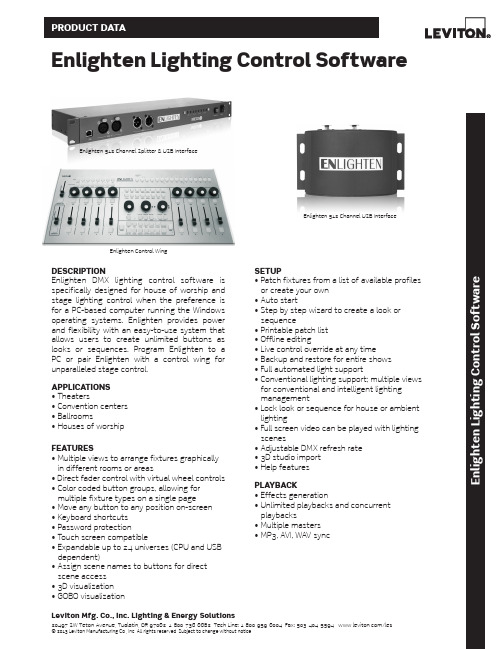
Leviton Mfg. Co., Inc. Lighting & Energy Solutions20497 SW Teton Avenue, Tualatin, OR 97062 1-800-736-6682 Tech Line: 1-800-959-6004 Fax: 503-404-5594 /les© 2013 Leviton Manufacturing Co., Inc. All rights reserved. Subject to change without notice.E n l i g h t e n L i g h t i n g C o n t r o l S o f t w a r eDESCRIPTIONEnlighten DMX lighting control software is specifically designed for house of worship and stage lighting control when the preference is for a PC-based computer running the Windows operating systems. Enlighten provides power and flexibility with an easy-to-use system that allows users to create unlimited buttons as looks or sequences. Program Enlighten to a PC or pair Enlighten with a control wing for unparalleled stage control.APPLICATIONS • Theaters• Convention centers • Ballrooms• Houses of worshipFEATURES• Multiple views to arrange fixtures graphically in different rooms or areas• Direct fader control with virtual wheel controls • Color coded button groups, allowing for multiple fixture types on a single page • Move any button to any position on-screen • Keyboard shortcuts • Password protection• Touch screen compatible• Expandable up to 24 universes (CPU and USB dependent)• Assign scene names to buttons for direct scene access • 3D visualization • GOBO visualizationSETUP• Patch fixtures from a list of available profiles or create your own • Auto start• Step by step wizard to create a look or sequence• Printable patch list • Offline editing• Live control override at any time • Backup and restore for entire shows • Full automated light support• Conventional lighting support; multiple views for conventional and intelligent lighting management• Lock look or sequence for house or ambient lighting• Full screen video can be played with lighting scenes• Adjustable DMX refresh rate • 3D studio import • Help featuresPLAYBACK• Effects generation• Unlimited playbacks and concurrent playbacks• Multiple masters • MP3, AVI, WAV syncEnlighten Lighting Control SoftwareEnlighten 512 Channel Splitter & USB InterfaceEnlighten Control WingEnlighten 512 Channel USB InterfacePRODUCT DATAEDITING FEATURES• Program looks at scenes step-by-step without the wizard with ease• Palette presets (foundation of the programming system; position presets)• Palettes automatically created on Patching or custom• Absolute and relative movement• Step-shift and shape-shift• Shape generator for movements with offsets • Shape library features an easy-to-use present effects lab• Macros• LED matrix engine and LED macros• MIDI, AVI, MPEG and WAV event sequencing and programming• Unlimited assignment of the following:- Fixtures- Buttons- Support fixtures- Button groups- Fixture groups• Unlimited pages of button triggers:- Still looks- Sequences- Multiple buttons- Timeline schedules• Spotlight mode: lock a button/look; once locked it cannot be released or overwritten • SOLO fixture modeINPUT/OUTPUT• DMX Outputs—up to 12,288 DMX channels • Ethernet—Artnet output• Optically isolated outputs• MIDI In/Output:- Assignable MIDI command for eachbutton and submaster for externalhardware control- MIDI input will trigger looks CONTROL WING• 8 high-quality sliders• 1 grand master• 1 manual crossfader• 11 job wheels for attributes and function control• 8 bump buttons• 32 assignable or preset direct access buttons with dry erase area• LED backlit button shows user interaction • Programming and playback function in one unit• USB <-> DMX Interface built in, 2 universe, 1024 channels• USB connector and LED indicatorSPLITTER• Enlighten DMX to USB interface built-in• Front and rear DMX input• 4 outputs• 3-pin and 5-pin XLR connectors on each output• Power and DMX status LEDs• Selectable DMX terminator• Rack or wall mountable• Opto isolated outputsE n l i g h t e n L i g h t i n g C o n t r o l S o f t w a r eLeviton Mfg. Co., Inc. Lighting & Energy Solutions20497 SW Teton Avenue, Tualatin, OR 97062 1-800-736-6682 Tech Line: 1-800-959-6004 Fax: 503-404-5594 /les© 2013 Leviton Manufacturing Co., Inc. All rights reserved. Subject to change without notice.SPECIFICATIONSPRODUCT DATAG-9005/C13-tbLeviton Manufacturing Co., Inc. Global Headquarters201 N. Service Rd. Melville, NY 11747-3138 • Tech Line: 1-800-824-3005 • Fax: 1-800-832-9538Leviton Manufacturing Co., Inc. Lighting & Energy Solutions20497 SW Teton Avenue, Tualatin, OR 97062 • Tel: 1-800-736-6682 • FAX: 503-404-5594 • Tech Line (6:00AM-4:00PM P.S.T. Mon-Fri): 1-800-959-6004Leviton Manufacturing of Canada, Ltd.165 Hymus Boulevard, Pointe Claire, Quebec H9R 1E9 • Telephone: 1-800-469-7890 • FAX: 1-800-563-1853Leviton S. de R.L. de C.V.Lago Tana 43, Mexico DF, Mexico CP 11290 • Tel. (+52) 55-5082-1040 • FAX: (+52) 5386-1797 • .mxVisit our Website at: /les© 2013 Leviton Manufacturing Co., Inc. All rights reserved. Subject to change without notice.ENLIGHTEN SCREENSHOTSAdd New Page Screen MFX SelectionMaster Fader Screen。
MADRIX灯光控制系统软件中文说明书
目 录1. 概述1.1分区1.2 接线1.3 启动和关闭1.4 观测器Avolites Visualiser1.5 控台模拟器The Pearl simulator1.6 准备工作2. 配置2.1 总清除2.2 配置常规灯2.3 配置摇头灯2.4 标记2.5 调节灯具的地址码2.6 重置灯具地址码2.7 辅助功能2.8 完成配置2.9 保存程序2.10 范例3. 手动控制灯具3.1 控制常规灯通道3.2 控制灯具3.3 修改灯具属性3.4 选色器3.5 使用灯具组群3.6 复制其他灯具上的设置 – Align 3.7 发散模式3.8 范例4. 素材4.1 使用素材4.2 创建素材4.3 储存素材4.4 共享素材和独立素材4.5 范例5. 图形5.1 何为图形5.2 选择图形5.3 修改图形大小和速度5.4 修改图形位置5.5 多台灯如何展示同一图形?5.6 范例6. 场景6.1 HTP和LTP通道6.2 编程时控台是如何运作的6.3 储存场景6.4 场景重放6.5 滚筒翻页6.6 标记滚筒6.7 复制场景6.8 删除场景6.9 编辑场景6.10 Include剪贴功能6.11 设置场景的转换时间6.12 灯具或通道储存6.13 调用场景中的图形6.14 范例7. 程序7.1 何为程序7.2 储存程序7.3 运行程序7.4 设置速度和交叉换场7.5 为程序取名7.6 编辑程序7.7 复制程序7.8 删除程序7.9 校时、剧本程序和场景控制7.10 音乐同步7.11 范例8. 剧场叠加8.1 设置剧本模式8.2 剧场控制8.3 编辑剧目8.4 剧目取名8.5 设置转换时间8.6 剧目转换8.7 运行9. 运行演出程序9.1 演出时间9.2 暂时锁住控台9.3 运行模式9.4 运行中手动控制9.5 主推杆9.6 通道模拟物10. 高级功能11. 与老控台的区别11.1 本机新特性11.2 转轮控制数值11.3 Preset Focuses改为素材键Palettes 11.4 “程序”包含“图形”11.5智能属性显示11.6 标记11.7 其他特性1. 概述本手册是为了让您最有效地使用我们的控制台而设计的,共分两部分。
新版核磁共振分析应用软件用户手册——Ver 1.0

纽迈电子科技有限公司
核磁共振分析应用软件 Ver 1.0
3、打开........................................................................................................ 41 4、反演........................................................................................................ 42 第三章 分析软件系统参数........................................................................................ 45 一、引言.............................................................................................................. 45 二、标准样品...................................................................................................... 45 三、系统参数...................................................................................................... 45 1、射频信号频率主值(Spectrometer Frequency,SF) ............................. 45 2、射频信号频率偏移量(Frequency Offset 1,O1) ................................. 45 3、90°和 180°射频脉宽(90° &180° Pulse Length,P1& P2) ................ 46 4、射频线圈死时间(Probe Dead Time,DT1).......................................... 46 5、接收机死时间(Receiver Dead Time,DT2) ......................................... 46 第四章 FID 实验 ........................................................................................................ 47 一、引言.............................................................................................................. 47 二、脉冲序列参数.............................................................................................. 47 1、信号采样点数 TD ................................................................................. 48 2、接收机带宽 SW..................................................................................... 48 3、信号采集的总时间 ACQ ...................................................................... 49 4、开始采样时间的控制参数 RFD ........................................................... 49 5、重复采样等待时间 TW ........................................................................ 51 6、增益 RG1,DRG1 和 PRG ................................................................... 51 7、重复采样次数 NS ................................................................................. 52 三、实验步骤...................................................................................................... 52 四、实验技巧...................................................................................................... 53 1、RG1,DRG1 和 PRG ............................................................................ 53 2、TW ......................................................................................................... 54 3、NS .......................................................................................................... 54 4、样品温度................................................................................................ 54 五、小结.............................................................................................................. 54 第五章 硬脉冲回波实验............................................................................................ 57 一、引言.............................................................................................................. 57 二、脉冲序列参数.............................................................................................. 57 1、信号采样点数 TD ................................................................................. 57 2、接收机带宽 SW..................................................................................... 58 3、开始采样时间的控制参数 RFD ........................................................... 应用软件 Ver 1.0
医用X射线图像质量控制系统

技术发展方向
改进图像处理算法,提高图像质量,同时降低处理时间和计算资源消耗。
优化软件算法
强化硬件设施
完善系统安全性
采用高性能的硬件设备,提高系统的运行速度、数据处理能力和稳定性。
加强系统安全防护,确保数据和系统的稳定性、可靠性和安全性。
03
系统性能优化建议
02
01
利用互联网和通信技术,实现远程提交申请、传输图像和诊断结果,提高诊断的及时性和便捷性。
临床需求的变化系统背景 Nhomakorabea提高X射线图像质量
减少辐射损伤
提升诊断准确率
系统目标
系统构成
X射线探测器
用于接收X射线并转换成电信号,使图像得以形成。
X射线源
医用X射线机的主要部件包括X射线管、高压发生器、冷却系统等。
数据处理系统
对采集到的X射线数据进行处理、分析和存储。
存储介质
用于存储X射线图像数据,可随时调取查看。
对医疗效率的提升
系统发展与改进建议
06
智能化技术
引入人工智能和机器学习等技术,实现图像的自适应处理、智能分析和辅助诊断等功能。
数字化技术
利用先进的数字化技术,提高图像的分辨率、对比度和清晰度,同时降低辐射剂量。
多模态技术
开展多种医学影像技术的融合,如X射线、CT、MRI等,以提高诊断的准确性和可靠性。
图像处理软件
多种图像处理功能
采用先进的图像增强算法,如直方图均衡化、锐化、噪声去除等,使图像更清晰、更易于分析和诊断。
图像增强算法
具备直观的可视化界面设计,方便医生进行图像处理和编辑。
可视化界面设计
大容量存储
支持多级存储和备份,确保图像数据的安全性和完整性。
MRIcro中文说明书样本
MRIcro中文说明书样本MRIcro 使用说明( 人工翻译版)MRIcro系统win95或者随后的Linux系统需求x86,或SUN微系统的x86 ( 我觉得这不是问题, 支持32位的就行)硬件支持16或24位色的当前版本 1.40 build 1( 这说明书有点老叻)费用免费作者Chris Rorden描述:把医疗图像转化为SPM友好分析格式。
( SPM, 即Scanning Probe Microscopy, 扫描探针显微) 。
能够逐次分析查看分析格式的图像。
创立分析格式的头文件。
创立3D兴趣区域( 经过计算容量和密度)兴趣区域的多层叠加。
旋转图像来符合SPM的模版图像。
输出图像格式包括BMP, JPEG, PNG, TIF。
结合图像: 多个图像的相关查看。
( 观察相同坐标的PET或MRI扫描)介绍MRIcro允许在装有windows和Linux系统的电脑上浏览医疗图像。
这是一个单机运行的程序, 这她包裹郑重补充SPM的工具。
MRIcro能够有效率的浏览和输出脑图像。
除此之外, 它还能使神经生理学家鉴定有意义的区域。
MRIcro能够创立给其它平台输出脑图像的分析格式的头文件。
对其它Windows程序熟悉的使用者将发现这个软件非常简单好用。
把鼠标停在按钮上一段时间将在这个按钮上出现一个文字暗示。
万不得已, 我们还揍了一个简要的使用手册来描述基本的功能。
加载图像和主信息面板MRIcro能够浏览各种各样的图像格式, 包括SPM分析格式。
分析格式的图像包括两个部分: 一个是包括原始图像资料的img格式文件和一个描述图像维度的hdr格式的文件。
MRIcor的住信息面板显示了头文件的信息和一系列的按钮这样你就能够打开浏览头文件。
Open Analyze format hdr/img pair这个按钮是你能有留言Analyze或者NIfTI格式的图像。
当你按下这个按钮的时候, 一个是你选择头文件去打开的对话会出现。
MADRIX 创意 LED 灯光控制系统说明书

POWERFUL PRODUCTS FOR CREA TIVE LED LIGHTINGAward-Winning Projects 2018Ultimate ControlMADRIX ® 5 is the ultimate control software for LED lighting. All-new features such as the TRI effect category, audio playback for videos, the CSV fixture list import, a fresh user interface with two themes that is even easier to use, unprecedented performance and speed thanks to the powerful new 64-bit render engine, and many more allow you to produce amazing results right from the start. Cutting-edge technologies provide you with all the tools you need for modern LED control.Ultimate CreativityBring your LED design to life with beautiful colors, stunning visuals, and spectacular effects. MADRIX ® 5 adapts to your needs. Use it as LED lighting controller , VJ software, 2D pixel mapper , 3D voxel mapper , media server , or media creator . This software is very easy to use with a VJ-like operation, 2 decks and a crossfader , plus 3 real-time previews to show your effects in advance.Audio-Reactive VisualsMADRIX ® 5 features a state-of-the-art audio analysis. It can process any live audio signal and create stunning real-time lighting visuals. These live effects will create a light show that runs in sync with your music. And thanks to the integrated effects generator , you can also create many lighting patterns without audio input. And you can always customize everything, such as speed, color , shape, direction,size, movement, position, brightness, and much more.best out of your LEDs. MADRIX ® 5 can produce a complete LED light show from a normal computer or laptop. Still, it can drive tens of thousands of LEDs without problems. This powerful software will not only allow you to control nearly any 2D LED display in every possible way, but real 3D LED applications as well. This makes it the ideal solution for your LED project.MADRIX 5 SoftwareUser Interface LanguagesDeutsch (German), English, Español (Spanish), Français (French), Italiano (Italian),日本語 (Japanese), Português brasileiro (Brazilian Portuguese), русский (Russian), Türkçe (T urkish), 简体中文 (Simplified Chinese)Industry Standards For Output DMX-BasedDVI-BasedMADRIX ® 5 excels in flexibility. Y ou can directly connect to a wide range of LEDs and compatible first-party or third-party LED controllers:Art-Net (I, II, 3, 4) (Unicast & Broadcast), DMX512, Philips Color Kinetics KiNET (V1 / V2),Philips Hue, SPI (Via MADRIX ® NEBULA), Streaming ACN (sACN / E1.31) (Unicast & Multicast)ColourSmart Link, Colorlight A8, Colorlight 5A, Colorlight T9, DVI (VGA, HDMI, and more), Eurolite T9Industry Standards For InputInteroperability, Remote Control, And AudioMADRIX ® 5 easily integrates with other lighting desks, consoles, controllers, and many other hardware or software tools:Art-Net (I, II, 3, 4), ASIO, Blackmagic Design (DeckLink, Intensity, and more), CAST Software BlackTrax, CITP , DMX512, GamePort, MA-Net 1 / MA-Net 2,MADRIX ® I/O, MADRIX ® ORION, Media (Images, Pictures, Logos, Videos, T ext, Live-Signal Capturing, Screen Capturing), MIDI, NewT ek NDI (Send & Receive), Remote HTTP (Web Server), Spout (Send & Receive), Streaming ACN (sACN / E1.31), Time Code (Art-Net / MIDI / SMPTE / System Time), WDM Supported Operating Systems Microsoft Windows 1064 bit onlyLicense Requirements MADRIX ® 5 licenses require a valid, metallic MADRIX ® KEY.Demo VersionDownload MADRIX ® 5 from SpecificationsEven more options are available via converters or bridging tools for input as well as output.2D Pixel MappingThe MADRIX® 5 Software makes it possible to controlsharp visuals on your LEDs.3D Voxel Mapping In X, Y, And ZMADRIX® 5 provides a leading-edge feature set to fullycontrol real 3D LED matrices. MADRIX® 5 supports volumeyour installation state-of-the-art.Combine 2D And 3Dcustomers, and clients. MADRIX® 5 is a powerful tool thatLEDs is fast, creative, and fun. MADRIX® 5 certainly takesyour LED display to the next level.MADRIX 5 LicensesDifferent licenses are available for different needs and project sizes.MADRIX ® 5 License UpgradesYou can easily upgrade the license on your MADRIX ® KEY to any higher license at any time in order to increase the available output. MADRIX ® 5 License Upgrades can simply be processed online. Please contact your dealer for moreinformation.MADRIX ® 5 Licensestartentrybasicprofessional1,0244,09616,38465,5362832128341 1,3655,46121,8454,096 16,384262,1441,048,57664 x 64128 x 128512 x 5121,024 x 1,024LifetimeLifetimeLifetimeLifetimeMADRIX ® 5 Licenseultimatemaximumpreprogrammer262,1441,048,576MADRIX ® 5 preprogrammer is a special license available for project preparation. It provides no output for MADRIX ® 5, but removes major limitations of the demo mode.5122,048 87,381 349,5252,097,1522,097,1522,048 x 1,0242,048 x 1,024Lifetime Lifetime LifetimeThat is why today‘s DMX lighting fixtures are equipped with Remote Device Management. It is a two-way communication for receiving instructions as well as sending out feedback. When devices report back data, you gain access to a whole new level of available information, insights, and control. MADRIX® RADAR is the complete toolbox to make the most of this data; automatically and efficiently.Supervise all of your lighting fixtures in a single software. Handle large amounts of RDM devices. It is a new kind of application that opens up entirely new possibilities for you and your clients. MADRIX® RADAR includes automatic fixture patching, fully automatic 24/7 device monitoring, automatic e-mail notifications, and much more.Transform how you work with luminaires. Easily configure settings remotely. Let the software monitor devices automatically for you. Quickly see the results in graphical overviews at a single glance. That means that your setup and maintenance processes are much faster, much easier, and much more cost-efficient than ever before.Build a database of past sensor data and see the progressionof device parameters, such as temperature and operating hours. Exchange devices that are likely to fail soon, before they do. Make your maintenance costs much more predictable by planning them more effectively in advance.NEWMADRIX RADAROverview. Visualize how it works.Provide unparalleled support for each installation.,®If MADRIX®MADRIX RADARMADRIX® RADAR is an independent software that allows you to choose compatible RDM nodes.Y ou gain the enormous advantage with MADRIX® RDM nodes of running a fully integrated system. Our MADRIX® hardware processes RDM data packages in a way that does not result in interference with DMX data packages during full and live operation, which could lead to visual flickering or other signal interruptions. MADRIX® interfaces manage these data streams highly efficiently and intelligently.The MADRIX® System. Take advantage of high-quality software and high-quality hardware. License Model. Integrate flexibly into your projects.MADRIX® RDM NodesThird-Party RDM Nodes & MADRIX® RADAR LicenseSoftware License No additionalsoftware license is required.DemoMADRIX®RADARfusion smallMADRIX®RADARfusion mediumMADRIX®RADARfusion largeRDM Devices/Sub-Devices All connected devices areautomatically unlocked for free.2322562,048 ManagementConfigurationMonitoringBig DataAvailable as a separate1-year MADRIX® RADAR big data license, which can be renewed.MADRIX RADAR Screenshots. Have a closer look.SpecificationsUser Interface Languages EnglishSupported Operating Systems Microsoft Windows 1064 bit onlyLicense Requirements MADRIX® RADAR licenses require a valid, metallic MADRIX® KEY.Demo Version Download MADRIX® RADAR from MADRIX ® 5 Software:Crash CourseMADRIX ® Effects, and much more.of effects.MADRIX ® 5 in order to be able to scope.Receive MADRIX ®MADRIX ® 5 Software:Creating Advanced EffectsMADRIX ® 5 Software:Patching, Mapping, And Group Control***************123MADRIX KEY Y our key to the world of MADRIX®.Flexible UsageThe MADRIX® KEY is a USB dongle that unlocks the features or output for the MADRIX® 5 Software or MADRIX® RADAR Software by holding the corresponding license. You can freely switch between different PCs as it is not bound to a specific system. It only needs to be activated online once.What’s In The BoxThe beautiful, high-quality box includes 1x empty MADRIX®KEY, 1x USB flash drive incl. MADRIX® 5 Software and MADRIX® RADAR Software, 1x lanyard, and 1x quick start guide. All additional software tools and all user manuals areprovided digitally.® hardware interfaces or ou can also directly adjust the overall Live Recordingrecording a beautiful light show with MADRIX® 5 is as easy as pressing record and play.Time-Controlled ShowsWeb ConfigurationRemote ControlTrigger MADRIX® AURA via HTTP commands and the built-in web server or use Art-Net/sACN. Y ou can even add MADRIX® ORION for interactive installations.3 versions are available: AURA 2 | AURA 8 | AURA 32NEWSpecificationsSupply Of PowerDC 5 V – 24 V; connection via 2-pin, pluggable screw terminal or via 5 V USBPower Consumption < 1.5 W (300 mA) during normal operation (500 mA max. fused)Network Protocols Art-Net, Streaming ACNOutput2x / 8x / 32x 512 DMX channels output over Ethernet network Recording Input 2x / 8x / 32x 512 DMX channels input over Ethernet network Remote-Control Input 8x 512 DMX channels received over Ethernet network Ethernet 2x RJ45, Auto MDI-X, daisy-chain support, 10/100/1000 MBit/s SD-Card Slot Supports SD, SDHC, and SDXC cards USB Port USB 2.0, type B plugHandling 8 control buttons, 5 status LEDs (+ 4 network status LEDs)Dimensions 86 mm x 105 mm x 49 mm (L x W x H)Weight148 g | 154 g incl. screw terminal, SD card, and wall mounts Operating T emp.-10 °C to 70 °C Storage T emp.-20 °C to 85 °CRelative Humidity 5 % to 80 %, non-condensing (Operating / Storage)Case Non-conductive, V-0 flammability rating (UL94 test method), designed for 35 mm DIN-rails or wall mounting IP Rating IP20CertificatesCE, FCC, RoHSMADRIX AURAThe MADRIX ® AURA is the central stand-alone controller for simple recording and large-scale pixelmapping. It redefines what is possible in a compact control unit with exceptional performance.. In addition, simply connect ® 5 over USB.® LUNA offers powerful features, especially in® 5. Take full advantage of pixel″ x 1U or 19″ x 2U. They feature a 4/8/16 DMX-OUT + 1 DMX-INsame time for larger projects.3rd-Party ControllersMADRIX® LUNA complies with the official protocol other consoles, controllers, or software solutions.Sync ModeMADRIX® 5 and MADRIX® hardware allow you to fully without visual interruptions.Invaluable Featuresconfiguration page.3 versions are available: LUNA4 | LUNA 8 | LUNA 16SpecificationsPower Supply AC 100 V – 240 V , 50-60 Hz, 0.4 A max., IEC C14 inlet Power Consumption < 1.5 W during normal operation USB Port USB 2.0, type B plugDMX512 (OUT)4x / 8x / 16x 512 DMX channels output DMX512 (IN)1x 512 DMX channels input DMX512 Ports (OUT)5-pin, XLR, female, NEUTRIK DMX512 Port (IN)5-pin, XLR, male, NEUTRIKEthernet 1x RJ45, Auto MDI-X, NEUTRIK etherCON, 10/100 MBit/s(Compatible with 1 GBit/s)Size19˝ x 1U (LUNA 4 / LUNA 8) | 19˝ x 2U (LUNA 16) Dimensions (Body Only)76 mm x 440 mm x 44 mm (L x W x H)Dimensions (T otal)76 mm x 482.6 mm x 44 mm (L x W x H)Dimensions (LUNA 16)76 mm x 482.6 mm x 88 mm (L x W x H)Weight1.3 kg (LUNA 4) | 1.4 kg (LUNA 8) |2.0 kg (LUNA 16)Operating T emp.-10 °C to 60 °C Storage T emp.-20 °C to 70 °CRelative Humidity 20 % to 80 %, non-condensing (Operating / Storage)Case Metal enclosure IP Rating IP20CertificatesCE, FCC, RoHSMADRIX LUNAThe MADRIX ® LUNA reliably distributes DMX512 data over long or short distances using Ethernet network or USB. Its sync mode makes sure that lighting effects look their best on the LEDs.76mm44mm4826m m44mm76m m44mm4826mm88mm®5 over USB.® STELLA offers powerful features. Managing the RDM & Daisy-Chain Supportas well as linearly daisy-chaining several devices together . On top, the device supports the Remote Device Management standard.Designed For DIN Rails Or Wallsto turn them off.3rd-Party ControllersMADRIX ® STELLA complies with official protocol other consoles, controllers, or software solutions.Sync ModeMADRIX ® 5 and MADRIX ® hardware allow you to fullywithout visual interruptions.MADRIX STELLASpecificationsSupply Of Power DC 5 V – 24 V; connection via 2-pin, pluggable screw terminal or via 5 V USBPower Consumption< 1.5 W (300 mA) during normal operation (500 mA max. fused)USB Port USB 2.0, type B plugDMX5122x 512 DMX channels, input and/or output DMX512 Ports 2x ports (Via 2x 3-pin, pluggable screw terminals)Ethernet 2x RJ45, Auto MDI-X, 10/100 MBit/s(Compatible with 1 GBit/s)Dimensions 90 mm x 70 mm x 46 mm (L x W x H)Weight108 g | 125 g incl. screw terminals and wall mounts Operating T emp.-10 °C to 70 °C Storage T emp.-20 °C to 85 °CRelative Humidity 5 % to 80 %, non-condensing (Operating / Storage)Case Non-conductive, V-0 flammability rating (UL94 test method), designed for 35 mm DIN-rails or wall mounting IP Rating IP20CertificatesCE, FCC, RoHSThe MADRIX ® STELLA is a dedicated control interface for DMX512 and Art-Net or Streaming ACNthat is designed for high quality and practicability in permanent LED installations.. In addition, ® 5 over USB.Quality Output Of 8 UniversesLED. Y ou can choose the output protocol separately for each of the two ports.Sync Mode & Daisy-Chain SupportMADRIX® 5 and MADRIX® hardware allow you to fullyseveral devices together.Invaluable Featuresdevice settings using the built-in web configuration page.MADRIX NEBULASpecificationsSupply Of PowerDC 5 V – 24 V; overA) 2-pin, pluggable screw terminal (12 A max.), B) 5 V USB, C) Port 1 or 2 sourced from LEDs;6 A max. load per port when supplying through to LEDs Power Consumption < 1.5 W (300 mA) during normal operation (500 mA max. fused)USB Port USB 2.0, type B plugData Output 8x 512 channels SPI TTL (Maximum output per port:680 RGB LEDs / 512 RGBW LEDs / 2048 1-channel LEDs)Ports 2x ports (Via 2x 4-pin, pluggable screw terminals)Ethernet 2x RJ45, Auto MDI-X, 10/100 MBit/s(Compatible with 1 GBit/s)Supported LEDsAs of March 2019. See for the latest information.APA101 / APA102 / APA104 / APA106 / GS8207GW6201 / GW6205 / LPD1882S / LPD6803 / LPD8806 MBI6120 / P9883 / SJ1221 / SK6812 / SK6822 SM16703 / SM16716 / TLS3001 / TLS3008 TM1804 / TM1809 / TM1812 / TM1814 / TM1829UCS1903 / UCS2903 / UCS512B3 UCS8904 / UCS9812S WS2801 / WS2803 WS2811 / WS2811S / WS2812 WS2812B / WS2813 / WS2815 / WS2818 WS2822S / WS2822S Addressing Dimensions 90 mm x 70 mm x 46 mm (L x W x H)Weight110 g | 132 g incl. screw terminals and wall mounts Operating T emp.-10 °C to 70 °C Storage T emp.-20 °C to 85 °CRelative Humidity 5 % to 80 %, non-condensing (Operating / Storage)Case Non-conductive, V-0 flammability rating (UL94 test method), designed for 35 mm DIN-rails or wall mounting IP Rating IP20CertificatesCE, FCC, RoHSThe MADRIX ® NEBULA directly connects to your LED pixels. This advanced SPI decoder receivescontrol data over Ethernet network or USB and is built to provide excellent image quality.Art-Net / Streaming ACN / USBsoftware or hardware controller. In addition, simply connect to MADRIX® 5 over USB.Versatile Outputseparately set as Analog-IN, Digital-IN, Counter, and other useful functions.Daisy-Chain Supportfor better cable management.Invaluable Featuresconfiguration page.MADRIX ORIONSpecificationsSupply Of PowerDC 5 V – 24 V; overA) 2-pin, pluggable screw terminal with 500 mA max. load per port when supplying through to the ports, B) 5 V USB, C) Port 1 or Port 2Power Consumption < 1.5 W (300 mA) during normal operation (500 mA max. fused)USB Port USB 2.0, type B plug Input Signals 0 V – 12 V , analogPorts 2x ports (Via 2x 6-pin pluggable screw terminals)Input Pins 2x 4 separate pins (8x in total)Ethernet 2x RJ45, Auto MDI-X, 10/100 MBit/s(Compatible with 1 GBit/s)Dimensions 90 mm x 70 mm x 46 mm (L x W x H)Weight105 g | 120 g incl. screw terminals and wall mounts Operating T emp.-10 °C to 70 °C Storage T emp.-20 °C to 85 °CRelative Humidity 5 % to 80 %, non-condensing (Operating / Storage)Case Non-conductive, V-0 flammability rating (UL94 test method), designed for 35 mm DIN-rails or wall mounting IP Rating IP20CertificatesCE, FCC, RoHSThe MADRIX ® ORION is specifically designed as a general-purpose input device for analog input and Ethernet-based output for remote control and interactivity.® 5 can be controlled remotely using the implemented SpecificationsSupply Of Power DC 5 V , 500 mA, Power over USB USB Port USB 2.0, type A plug, 2 m cable DMX512512 DMX channels, input or output DMX512 Port 5-pin, XLR, female, NEUTRIK Weight105 g Operating T emp.10 °C to 50 °C Storage T emp.-10 °C to 70 °C IP Rating IP20CertificatesCE, FCC, RoHSMADRIX USB SMPTESpecificationsSupply Of Power DC 5 V , 500 mA, Power over USB Power Consumption ~ 50 mA during normal operationUSB Port USB 2.0, type A plug, Plug and Play, 2 m cablePlug 3-pin, XLR, female, NEUTRIK Weight110 gOperating T emp.10 °C to 50 °C Storage T emp.-10 °C to 70 °CRelative Humidity 5 % to 80 %, non-condensing IP Rating IP20CertificatesCE, RoHSSimply add time code synchronization to your projects.MADRIX ® I/OMADRIX ® I/O products are supplementary input and output devices. External equipment brings additional automation processes and interaction to any project using MADRIX ® 5.SMPTE Time CodeThis input device allows you to effortlessly use SMPTE time code for time synchronization across your equipment and multiple devices.Standard ConnectorsData is received via the 3-pin, female XLR connector . The device can simply be connected to any USB 2.0 port.Example Of UseSynchronize the automated playback of scenes and effects in MADRIX 5®by using the Cue List.DMX Channels1,0244,09616,38465,536DMX Universes (Example)2832128RGB Voxels (Example)341 1,3655,46121,845DVI Voxels4,096 16,384262,1441,048,576Render Resolution (Example)64 x 64128 x 128512 x 5121,024 x 1,024Upgradable ValidityLifetimeLifetimeLifetimeLifetimeMADRIX ® 5 LicenseultimatemaximumpreprogrammerDMX Channels262,1441,048,576Is a special license available for projectpreparation.It provides no output for MADRIX ® 5, but removes major limitations of the demo mode.DMX Universes (Example)5122,048 RGB Voxels (Example)87,381 349,525DVI Voxels2,097,1522,097,152Render Resolution (Example)2,048 x 1,0242,048 x 1,024Upgradable ValidityLifetime Lifetime LifetimeMADRIX ® RADAR Licensefusion smallfusion mediumfusion largebig dataRDM NodesMADRIX ®Third-PartyThird-PartyThird-Party AllRDM Devices / Sub-Devices All Connected322562,048Available as a separate license, which can be renewed.Management Configuration Monitoring Upgradable ValidityLifetime Lifetime Lifetime 1 YearMADRIXHardwareLUNA 4LUNA 8LUNA 16STELLANEBULA4x 512 DMX8x 512 DMX16x 512 DMX1x Or 2x 512 DMX8x 512 SPIAnd And And And / Or1x 512 DMX 1x 512 DMX 1x 512 DMX 1x Or 2x 512 DMX1x RJ45100 MBit/s1x RJ45 100 MBit/s1x RJ45 100 MBit/s2x RJ45 100 MBit/s2x RJ45 100 MBit/s19˝ Rack DIN-Rail Or Wall DIN-Rail Or WallAURA 2AURA 8AURA 32ORION USB ONE USB SMPTE2x 5128x 51232x 5128x / 16x 1x 512 DMXAnd And And Or 8x 5128x 5128x 5128x Analog Inputs 1x 512 DMX1x Analog Input2x RJ45 1 GBit/s2x RJ45 1 GBit/s2x RJ45 1 GBit/s2x RJ45 100 MBit/sThis input device allows you to effortlessly use SMPTE time code for time synchronization across multipledevices.Example of use:Cue ListDIN-Rail Or Wall DIN-Rail Or WallProduct Order Number Product Order NumberMADRIX OverviewProduct Order Number Product Order Number MADRIX® Network Nodes AccessoriesMADRIX® AURA 2IA-HW-001029XLR Gender Changer IA-HW-001002 MADRIX® AURA 8IA-HW-001025XLR Adapter Silver IA-HW-001006 MADRIX® AURA 32IA-HW-001026XLR Adapter Black (Premium Quality)IA-HW-001020 MADRIX® LUNA 4IA-HW-001014STELLA Accessory Replacement Set IA-HW-001024 MADRIX® LUNA 8IA-HW-001008NEBULA Accessory Replacement Set IA-HW-001023 MADRIX® LUNA 16IA-HW-001015ORION Accessory Replacement Set IA-HW-001022 MADRIX® STELLA IA-HW-001019DIN-Rail Power Supply 12 V IA-HW-001027 MADRIX® NEBULA IA-HW-001018Plug-In Power Supply 3 V – 12 V IA-HW-001028MADRIX® I/OMADRIX® ORION IA-HW-001021MADRIX® USB ONE IA-HW-001001MADRIX® USB SMPTE IA-HW-001016▪For prices and more information, please contact your local dealer.▪Online activation initially required one time for any software license, license upgrade, or update.▪Only one MADRIX® 5 License is possible per MADRIX® KEY.▪MADRIX® 5 License Upgrades and MADRIX® RADAR fusion License Upgrades to higher licenses are possible several times per MADRIX® KEY.▪The MADRIX® 5 Software Update is free of charge if you have bought MADRIX® 3 Software on April 01, 2017 or any later date.▪It is possible to have a MADRIX® RADAR fusion license and a MADRIX® RADAR big data license on a single MADRIX® KEY.© 2001 – 2020 inoage GmbHMADRIX® is a registered trademarkinoage GmbHWiener Straße 56 01219 Dresden Germany Web *********************Phone +49 351 862 6869 0/MADRIX.DE/MADRIX/MADRIX_Team/MADRIX_TeamJuly 2020。
GE X光控制器中文说明书

2
智能的用户界面 独立的控制器有两种形式,一种是稳定的人机 桌面架构,另一种是19英寸适配器版本,很 容易与用户现场的办公桌集成。
这种设计十分直观,并带有防疲劳检测的功 能,它借助大图形显示、旋扭控制、功能键、快捷键及直接 输入来达到目的。
内置的安全功能,如门机连锁监控,可显示在操作界面上。 冷却流率的看门狗信号,操作温度和其它系统的状态信息都 是清晰可见的。
这可以及时识别系统的运行状态和运行状况。
方便集成 TITAN E考虑到典型的OEM需求,为各种工业系 统集成提供了工具包,界面以及协议(RS232, Profibus总线)。
它可以实现X射线机完全的外部控制和远程的可视化----即便 没有和控制器连接。
320
13 4.5 4200 1500 4.0 1.5 5.50 3.00
3.0 / Be
ISOVOLT ISOVOLT ISOVOLT 320/13 320 M2 420/5
0.4 - 1.0 HP
320
13 5 4200 1680 3.5 1.5 6.30 3.00
320 5.6 2.5 1800 800
4
优势
优异的性能服务于广阔的领域。 ● 全自动训机(预热)程序,以及扩展的预热模式,保障了射线管的性能,实现射
线管的全面保护。 ● 智能直观的用户界面,可使多种集成成为可能,产生更高的生产效率。 ● 优越的剂量值、稳定的高压范围,使曝光最优化。 ● 可方便地与多种外部平台集成,例如自动检测系统,利用不同的界面特点实现设
8
双极
● RS232连接 ● 基于DIN54113的门机互锁 ● 基于美国射线控制法令1968,§ 1020.40 ● 预训机时间内额外的报警输出被激活 ● 外部的开始/停止 ● 外部的紧急停止 ● 冷却系统
MRIcroGL中文说明书

MRIcroGL中文说明书(人工翻译版)实时交互式渲染MRIcroGL是一个用来展示3D医学影像的程序。
通过你的电脑显卡,它可以进行实时交互式渲染。
程序内还包括了一些脚本来展示它的功能。
可以从NITRC来下载脚本介绍新用户们可以通过运行MRIcroGL的脚本来探索这个软件的特性。
高级用户可以创建他们自己的脚本来避免冗长乏味的手动调节。
只需从“View”菜单中选择“Scripting”按钮就可以运行或者创建脚本。
当一个新的名为“Scripting”窗口打开时,你就可以使用“File”菜单来打开现存的脚本。
当前打开的脚本则显示在文本编辑器中,并且你可以选择“Script”菜单中的“Run”来执行这个脚本。
指南包含一个详尽的脚本可用命令参考。
示例脚本这个脚本可以用来产生光源移动的图像来调整映像。
CONSTksteps = 220;kAziSpeed= 1;kElevSpeed= 1;kTime = 1;VARi, az, el: integer;BEGINRESETDEFAULTS;BACKCOLOR(255, 255, 255);LOADIMAGE('ch256');COLORNAME('surface');SHADERADJUST('specular',0.9);FOR i := 1 TO ksteps DO BEGINaz := (i* kAzispeed) mod 360;el :=(i* kElevSpeed) -60;SHADERLIGHTAZIMUTHELEVATION(az,el);WAIT(ktime);END;END.脑玻璃样脚本这个脚本示范了2014年发布的‘overlay glass’着色器,这个着色器允许你独立的控制背景透明度和重叠影像。
这个功能的辅导见demonstration YouTube video。
BEGINLOADIMAGE('mni152_2009bet');OVERLAYLOADSMOOTH(true);OVERLAYLOAD('motor');OVERLAYMINMAX(1, 2.5, 2.5);BACKCOLOR(255, 255,255);SHADERNAME('overlay_glass');SHADERADJUST('edgeThresh', 0.6);SHADERADJUST('edgeBoundMix', 0.72);END.Clipping脚本这个脚本示范了2014年发布的‘overlay’着色器允许你独立的控制背景透明度和叠加影像。
- 1、下载文档前请自行甄别文档内容的完整性,平台不提供额外的编辑、内容补充、找答案等附加服务。
- 2、"仅部分预览"的文档,不可在线预览部分如存在完整性等问题,可反馈申请退款(可完整预览的文档不适用该条件!)。
- 3、如文档侵犯您的权益,请联系客服反馈,我们会尽快为您处理(人工客服工作时间:9:00-18:30)。
M R I X灯光控制系统软件中文说明书集团文件版本号:(M928-T898-M248-WU2669-I2896-DQ586-M1988)目录1. 概述本手册是为了让您最有效地使用我们的控制台而设计的,共分两部分。
第一部分是辅导性的渐进指南,教您如何操作控制台。
第二部分是参考手册,其中包含所有控制台方面的知识。
如果您在看入门指南,又想知道更多的信息的话,可以直接到参考手册的同一章节查找。
本手册仅适用于“Pearl Expert”,并不适用于Pearl2008,2004,2000。
1.1分区本控台共分4个控制区:主控制区:用于设置总体级别预置区Preset Faders:用于选择和控制单个灯具重放区:用于选择和控制场景和程序编程区:用于配置和编程主要操纵件:预置推杆用于控制单个调光通道和灯具亮度推杆下面的2个按键用于选择灯具并让灯具发光的。
模式选择按键(Mode select key switch)用于设置操纵模式Program 表示编程, Run 运行程序,System 用于配置。
滚筒用于翻页,共2个滚筒,分别控制10个重放推杆。
主推杆控制控台各部分的总输出。
重放推杆和发光按键用于在运行程序时重放已经编好的场景。
显示屏是控制台的中枢,能展示多种屏幕信息。
转轮用于设置灯具的控制数值及灯速度和转换。
菜单按键(标有A-G)用于控制选项。
数字小键盘及其他控制键用于输入数值和改变控制。
灯具翻页键在数字小键盘上面,共4页。
蓝色命令按钮用于执行储存场景,复制,保存到磁盘等功能。
亮灯表示工作状态。
属性选择键用于选择由转轮控制的灯具属性,如颜色,图案,水平,调焦等。
亮灯表示工作状态。
底部红色按键用于控制灯具亮度。
控台前面的抽屉里有英文键盘和鼠标触摸屏。
背板控制台所有接口都在背板上。
当开关或推杆失灵时,请使用重启键。
DMX输出和主板将继续运行。
USB 保存插孔和开关是在出现问题时用来操控控制台的。
详情见第197页。
开关通常设置为“正常运行” Normal operation。
显示器提供的信息比控制台上的显示屏多。
主要用于设置控制台和编程。
显示器会显示你所输入的文档和数字。
空间不够时,没有它也能运行。
控制台的输出在显示器的桌面窗口中有显示。
控制台内置一个运行Microsoft Windows XP的电脑主板。
请使用显示器来操控Windows。
用右边工具栏上图标可以打开文件夹和磁盘浏览器,Windows 控制面板以及USBExpert的诊断软件,重启或者关闭控台软件。
1.2 接线使用前请先检查以下连接是否完毕。
连接时请关闭电源。
将电源插孔(the mains inlet)接到交流电源上。
本控制台提供80-260V 50-60Hz的宽电压,无需选择电压。
经常打开电源插座旁的那个开关。
外接显示器时,将电脑显示器接到控制台背板上的VDU输出口即可。
将灯具或调光器接到DMX输出口即可。
插上工作灯。
1.3 启动和关闭本机内部使用Windows操作系统,请正常关机而不只是关闭电源。
按下左前方的电源开关即可在30秒左右启动本机。
再按一次电源开关即可关机。
电源灯熄灭后方可拔去电源。
注意事项:中途断电,下次启动时比较缓慢。
建议使用UPS电源。
无法正常关机时,按住电源开关5秒钟即可强制关机。
1.4 观测器Avolites Visualiser略.1.5 控台模拟器The Pearl simulator略.1.6 准备工作其余部分是操作指南。
请按顺序操作。
操作时,准备一些摇头灯,有调光器Dimmer就更好了。
为便于编程,请备好下列物品:灯光操纵计划书空软盘空白磁带和标记笔纸笔或笔记本电脑灯具操作手册或者DMX表饮料请用意译而非直译2. 配置本章讲如何设置来控制调光器和灯具。
配置调光器配置摇头灯设置灯具上的地址码将灯具和调光器通过DMX线与控制台连接起来。
首先将灯具或者调光器分别分配由某个预置推杆控制。
推杆控制灯具或调光器的亮度;Swop按钮是编程时用来选灯的。
在“运行模式”下,Flash和Swop按钮控制发光。
配置DMX地址。
共可配置240台灯或调光通道。
用在数字键盘上面有4个灯具翻页键,每页有60个控件。
2.1 总清除重新设置前先做个总清除,以免受之前设置的干扰。
清除步骤:将钥匙调至“系统System模式”。
选择软键 A [Service]选择软键F [Wipe].按 F [“Wipe all], 确认清除。
将钥匙调至“程序Program模式”以备编程。
2.2 配置常规灯配置常规灯将钥匙调至系统“Program” 状态按下配置 Patch键按下 A [Dimmer]本机会从DMX 001开始配置 (如显示屏顶部显示).如果不是DMX001,你可以通过数字键盘来改变。
按下预置推杆下面蓝色的“Swop1”键。
本机将变为下一个地址码。
按其他键即可配置。
配置完毕请按“Exit”键退出。
如此,在“运行”模式下,即可通过推杆1来控制调光通道了。
按顺序配置21-30号控件的便捷方法:输入调光配置模式输入初始DMX通道。
按下第一个控件来配置21号控件。
按下最后一个SWOP按键来配置30号控件。
先放开第一个控件,然后放开最后一个控件。
每个控件将按顺序配置一个调光通道。
配置完毕,按“EXIT”退出。
同一控件可同时配置几个调光通道,步骤如下:输入调光配置模式用数字键盘来输入第一个须配置的地址码。
按下“SWOP”键来配置。
用数字键盘来输入下一个须配置的地址码。
按下“SWOP”键来配置。
配置完毕,按“EXIT”退出。
配置其他调光通道,同法。
查看配置:按View,然后按 C [DMX patch] 显示每个DMX通道分配到哪个控件。
或D [Fixture patch], 控件菜单。
2.3 配置摇头灯配置灯具:按下配置Patch 键。
按下 B [Choose a fixture] 键。
显示屏会在顶部显示“Please select a manufacturer”“请选择生产商”字样。
用 F and G 键来上下移动生产商菜单,然后按下灯具生产商旁的软键来选择它。
用同样的方法选择其他灯具。
“Use preset palettes”“使用预置素材?”按下 A [Yes].按下11号控件上的Swop来配置您为11号控件选择的灯具。
继续配置灯具,或者按“EXIT"退出。
配置一系列灯具:按住第一个按钮不放,然后按下最后一个按钮。
改变灯具种类按下 A [Select another fixture]从软键的菜单上选择“the fixture type”即可配置备注: 配置时可预先储存素材,预设素材包括9个位置,10种颜色,10种图案。
编程时按素材键即可使用。
本机共有ABCD四个输出线。
按E [Select a DMX line]即可配置任一DMX输出线。
2.4 标记在控件上方贴个标签方便编程时使用。
2.5 调节灯具的地址码使之与控台地址码一致。
展示灯具的地址码按下View按键按下D [Fixture Patch]按下 View 和C [DMX Patch] 查看地址码清单2.6 重置灯具地址码使用Re-patch Fixtures软键重置灯具的地址码.2.7 辅助功能使用Patch Utilities 软键设置灯具选项和插入通道的运行2.8 完成配置完成配置后按数字键盘上的Exit键退出,即可进行编程了。
2.9 保存程序将程序保存到USB 随身碟、软盘或内置硬盘上。
磁盘备份按下控台右下角的 Disk键插入 USB 随身碟或软盘选择 B [Save show to disk].按 A [Convert Show To Sept 2000]即可使之与老版控台的Sep 2000软件兼容。
在键盘上输入文件名,然后按Enter确认,或直接按Enter接受。
选择存储媒介。
插入存储媒介,按“Disk”键,再按A [Load show from disk],然后选择存储媒介,即可下载程序。
2.10 范例如何将6路调光台配置到31-36推杆上?按Patch, 再按 A [Dimmer].按住31蓝色按钮不放,然后按住36号蓝色按钮即可。
按“Exit”两次,推出“配置模式”最后设置调光台的地址码,使之与控台一致。
the display shows the DMX address where the handle is patched). 按View,然后按D [Fixture patch], 再通过Down Arrow键滚动到Handle31,即可How do I patch a Mac600 to handle 10按Patch键,再按B [Choose a fixture]按F [More] 直到其中一个软键的选项出现“Martin” 字样。
按下该软键选择该选项。
接着按住F [More]不放直到其中一个软键出现MMac600m4字样。
按下该软键选择该选项。
然后控台显示“Use preset palettes”按A [Yes].按下Swop10号按钮,即可配置灯具了按Exit两次,即可退出.最后只需设置Mac 600的地址码使之与控台一致即可。
3. 手动控制灯具控制灯具修改属性创建和使用 groupsalign and fan 功能查看控台输出手动控制灯具须在编程模式下进行,所有得先将钥匙转至编程Program模式。
3.1 控制常规灯通道将配置有常规灯的推杆推上去即可控制常规灯通道。
3.2 控制灯具首先选择需要控制的灯具(你可以选择一台或多台灯具)找灯按下控制灯具的Swop键。
Swop的LED灯亮表示灯具已选定。
显示器上有加粗显示。
重按Swop键即可取消选定。
按住第一个Swop键不放,接着按最后一个Swop键,即可选择一系列灯具。
按下控台右下角的Locate键,被选定的灯将垂直朝上亮灯。
3.3 修改灯具属性控台右下部的按键是用来选择属性的,转轮是用来控制的。
控制灯具的水平和垂直用Swop键来选灯按下控台右下角的Locate键来找到要控制的灯。
按下the Pan/Tilt键左边转轮控制垂直方向,右边转轮控制水平方向。
注:一旦属性被改变,下次灯具选择按键时,所有灯具都将自动被取消。
3.4 选色器如果您的灯具有CMY or RGB 混色功能,连接上VDU显示器,您可以用鼠标从银盘上的素材中选择一种颜色。
选色在VDU显示器上,从工具菜单Tools中选择选色器Colour Picker。
选择您要设置颜色的灯具,将其打开。
从素材中选择颜色即可。
顶部圆圈代表颜色,底部线条表示颜色的强度。
3.5 使用灯具组群将多个同一种类的灯具编成一个组群,为避免一个个选灯,输入该组群号即可选择所有同组灯具。
创建组群选择要编组的灯具按下ML菜单键后, 接着按 E [Record Group].在数字键盘上输入组群号1-200,按Enter即可。