JH-5600B中控说明书PDF
RX4000B、RX6000B无纸记录仪使用说明书

目录目录目录 (1)第1章概述 (3)1.1概述 (3)1.2主要特点 (3)1.3主要技术指标 (4)1.3.1 技术参数 (4)第2章开箱 (7)2.1外包装箱检查 (7)2.2开箱 (7)2.3装箱物品清单 (7)第3章安装与接线 (7)3.1使用环境 (7)3.2安装尺寸 (8)3.3安装步骤 (8)3.4接线 (9)3.4.1 端子说明 (9)3.4.2 接线端子的制作 (11)3.4.3 电源线的处理和连接 (12)3.4.4 信号线的连接 (12)3.4.5 通讯线的连接 (14)第4章按键与旋钮 (15)4.1键的类别 (16)4.2键的功能 (16)4.2.1 监控操作键 (16)4.2.2 组态操作键 (17)第5章组态设置 (17)5.1组态主菜单 (17)5.2系统组态 (18)5.3通道组态 (19)5.3.1 通道 (19)5.3.2 位号 (20)5.3.3 型号 (20)5.3.4 量程 (21)5.3.5 单位 (21)5.3.6 滤波时间 (22)5.3.7 断线 (22)5.3.8 小信号切除 (22)5.3.9 报警组态 (22)5.3.10 流量累积 (23)5.3.11 速率报警 (23)5.3.12 线性修正 (24)5.4流量组态 (24)5.4.1 流量通道 (24)5.4.2 温压补偿类型 (24)5.4.3 累积列表 (24)5.4.4 累积清零 (25)5.4.5 标况压力 (25)5.4.6 列表清零 (25)5.4.7流量模型 (25)5.4.8 结合开方功能选择流量模型 (26)5.4.9 设计工况条件的组态 (26)5.4.10 工作条件的组态 (26)5.4.11 线性温度补偿 (26)5.4.12 线性压力补偿 (26)5.4.13 退出组态 (27)5.5速率报警组态 (27)5.5.1 速率报警设置 (27)5.5.2 退出组态 (27)5.6线性修正组态 (27)5.7CF卡组态 (28)5.8输出组态 (29)第6章监控操作 (30)6.1画面综述 (30)6.1.1 画面简介 (30)6.1.2 画面切换 (30)6.2开机画面 (31)6.3多通道实时数显画面 (32)6.4单通道实时显示画面 (32)6.4.1 时标的放大与缩小 (33)6.4.2 自动翻页/手动翻页的切换 (34)6.5多通道实时显示画面 (34)6.6多通道棒图显示画面 (35)6.7报警列表画面 (35)6.8追忆画面 (36)6.9流量画面 (37)6.10日、月列表画面 (37)6.11打印画面 (38)第7章故障分析及排除 (40)第1章概述1.1 概述RX4000B/RX6000B无纸记录仪是针对各种工业现场的实际需求设计生产的,集显示、处理、记录、积算、报警和配电等多种功能于一身的新型记录仪。
多媒体使用技能实训指南
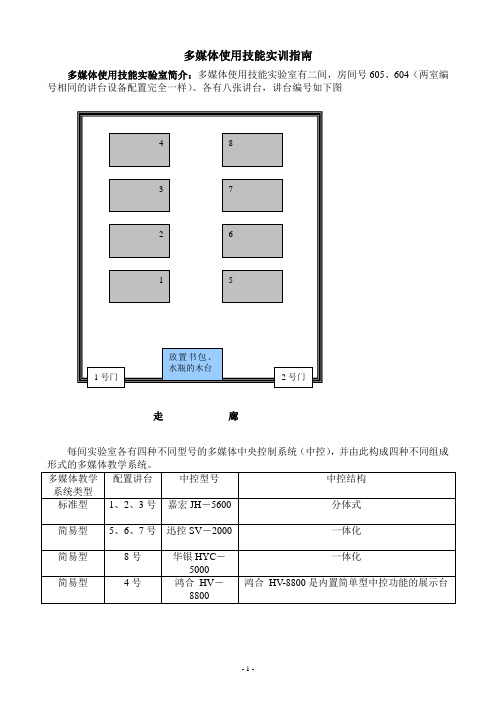
多媒体使用技能实训指南多媒体使用技能实验室简介:多媒体使用技能实验室有二间,房间号605、604(两室编号相同的讲台设备配置完全一样)。
各有八张讲台,讲台编号如下图走廊每间实验室各有四种不同型号的多媒体中央控制系统(中控),并由此构成四种不同组成多媒体教学系统的使用训练嘉宏JH-5600 组成(1-3讲台)的多媒体教学系统使用方法一、认识中控整个嘉宏中控系统包括控制面板、主控机、电源盒三部分,如下图1.控制面板(如下面为待机状态的示意图,待机时OFF按键上方的指示灯亮红色)控制面板调整音量的区域见下图系统都没有配置影碟机、录像机、卡座,因此公用功能键没有用到)2.中控主机前面板(如下面示意图)①红外接收:在红外线代码学习录入进时,接收来自遥控器的信号②电源指示:接通电源时亮③操作指示:主机通讯正常时会闪亮④学码指示:在红外代码学习录入时,以亮、闪亮等形式表示红外录码二、多媒体投影机1、认识(1-3号讲台)配置的夏普XR-N850SA投影机2、针对夏普(SHARP)投影机的使用注意:⑴打开镜头盖在开启投影机电源之前,确认镜间快门(镜头盖)完全打开,如下图开机注意:移动凸起条对准OPEN的黑色三角块,就是表示已经打开到正确位置。
如果没打开到位,投影机不能开机。
镜头调整:外边的镜头调整焦距(FOCUS)即画面的清晰度;里边的镜头为变焦镜头(ZOOM)即调整画面的大小。
⑵开启投影机按下中控面板上的投影机开机键。
POWER的指示灯闪烁,说明处于开机状态,1-2分钟后画面变亮。
(3)投影机的设置INPUT:按下INPUT按键,根据线路输入的连线,确认对应的输入信号。
其他设置:按下MENU,调出菜单,可根据需要进行调整。
夏普投影机的正常设置参数表多媒体系统中的其他设备一、展示台1、华银HY-61B展示台如下图2、展台控制按键如下图(1)本机为本机镜头拍下的信号(2)视频(1/2)分别对应后面板的VIDEO接口(3)计算机(1/2)分别对应后面板的RGB接口其他按键结合投影画面理解其功能。
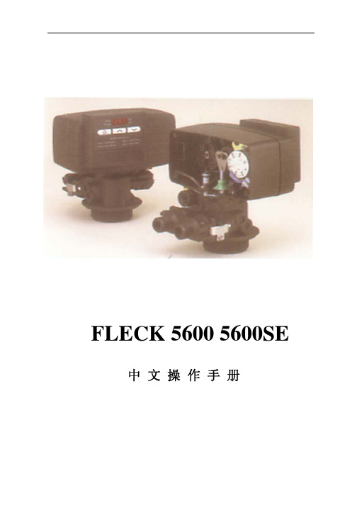
5600SE下风过滤器系统操作指南说明书

Master Programming Mode Flow Chart for Single Backwash ValvesWith Time of Day display set to 12:01 P.M., push and hold both the Set Up and Set Down buttons for 5 /Metric Display FormatExample: US display Format [U--1]Regeneration TypeExample: Meter Delayed Regeneration [7--3]Treated Water CapacityExample: 1,000 gallons/liters/cubic meters [1000]Regeneration TimeExample: Regenerate as needed at 2:00 A.M. [2:00]Regeneration Day OverrideExample: Regenerate at a minimum frequency of 3 days [A--3]Regeneration Cycle Step #1Example: 10 minute step time [1-10]Regeneration Cycle Step #2Example: 60 minute step time [2-60]Regeneration Cycle Step #3Example: 10 minute step time [3-10]Regeneration Cycle Step #4Example: 12 minute step time [4-12]Regeneration Cycle Step #5Example: Step 5 Cancelled [5OFF]Flow Meter SizeExample: 5600SE 3/4" Turbine Flow Meter [F133]Valve TypeExample: 5600SE Valve [o--1]Line FrequencyExample: 60 Hz Line Frequency [LF60]Master Programming Mode is exited,Normal Operation is resumedNOTE:1.Set Time of Day display to 12:01 P.M.2.Push and hold both the Set Up and Set Down buttons for 5 seconds.3.Push Extra Cycle button once per display until all displays are viewed and Normal Operation is resumed.4.Option setting displays may be changed as required by pushing either the Set Up or Set Down button.5.Depending on current valve programming certain displays will not be able to be viewed or set.6.Reference programming instructions for complete list of available settings.Page 1Master Programming Mode Flow Chart for Double Backwash ValvesWith Time of Day display set to 12:01 P.M., push and hold both the Set Up and Set Down buttons for 5 /Metric Display FormatExample: US display Format [U--1]Regeneration TypeExample: Meter Delayed Regeneration [7--3]Treated Water CapacityExample: 1,000 gallons/liters/cubic meters [1000]Regeneration TimeExample: Regenerate as needed at 2:00 A.M. [2:00]Regeneration Day OverrideExample: Regenerate at a minimum frequency of 3 days [A--3]Regeneration Cycle Step #1Example: 10 minute step time [1-10]Regeneration Cycle Step #2Example: 60 minute step time [2-60]Regeneration Cycle Step #3Example: 10 minute step time [3-10]Regeneration Cycle Step #4Example: 10 minute step time [4-10]Regeneration Cycle Step #5Example: 12 minute step time [5-12]Regeneration Cycle Step #6Example: Step 6 Cancelled [6OFF]Flow Meter SizeExample: 5600SE 3/4" Turbine Flow Meter [F133]Valve TypeExample: 5600SE Valve [o--1]Line FrequencyExample: 60 Hz Line Frequency [LF60]Master Programming Mode is exited,Normal Operation is resumedNOTE:1.Set Time of Day display to 12:01 P.M.2.Push and hold both the Set Up and Set Down buttons for 5 seconds.3.Push Extra Cycle button once per display until all displays are viewed and Normal Operation is resumed.4.Option setting displays may be changed as required by pushing either the Set Up or Set Down button.5.Depending on current valve programming certain displays will not be able to be viewed or set.6.Reference programming instructions for complete list of available settings.Page 2Master Programming ModeSet Up buttonExtra Cycle button Set Down buttonWhen the Master Programming Mode is entered, all available option setting displays may be viewed and set as needed. Depending on current option settings, some displays cannot be viewed or set.Entering Master Programming ModeSet the Time Of Day display to 12:01 P.M. Push and hold the Set Up and Set Down buttons together until the Program Dot turns on (about 5 seconds). Depending on current option settings, some displays cannot be viewed or set.Exiting Master Programming ModePush the Extra Cycle button once per display until all are viewed. The Program Mode is exited and normal operation resumes. Resetting Permanent Programming MemoryPush and hold the Set Up and Set Down buttons for 25 seconds or until the Time Of Day display resets to 12:00 P.M. All option settings reset to default values. Control programming must be reset as necessary./Metric Display Format (U)Push the Extra Cycle button. This display is used to set the desired display format. This option setting is identified by the "U"in the first digit. The possible settings are:US Format uses gallons for volume with a 12-hour timekeeping format. Regeneration timing in minutes.Example:[U - - I]Metric Format uses liters for volume and a 24-hour timekeeping format. Regeneration timing in tenths of minutes. Use the Set Up and Set Down buttons to adjust this value.Example:[U - - 2]Cubic Meter Format uses cubic meters for volume and a 24-hour timekeeping format. Regeneration timing in tenths of minutes. Use the Set Up and Set Down buttons to adjust this value.Example:[U - - 4]Page 3Master Programming Mode (Cont’d.)2.Regeneration Type (7)Push the Extra Cycle button. Use this display to set the Regeneration Type. This option setting is identified by the number "7"in the first digit. There are three possible settings:Timeclock DelayedThe control determines the day that a regeneration is required by the Regeneration Day Override setting (A). Once this day is reached, a regeneration cycle starts at the set Regeneration Time.Example:[7 - - I]Meter ImmediateThe control determines that regeneration is required when the available volume of treated water drops to zero. Regeneration begins immediately.Example:[7 - - 2] (This setting is typically used by the 9000SE)Meter DelayedThe control determines that a regeneration is required when the available volume of treated water drops to zero. Regeneration begins immediately at the set Regeneration Time. Use the Set Up and Set Down buttons to adjust this value.Example:[7 - - 3]3.Treated Water Capacity (No Display Code)Push the Extra Cycle button. Use this display to set the amount of water (gallons/liters/cubic meters) that can be treated by the unit before a regeneration cycle is required. With Meter Delayed Regeneration Type set, it is necessary for the programmer to determine a reserve capacity and subtract that value from the calculated full capacity of the unit. This display cannot be viewed with Timeclock Regeneration Type set. Use the Set Up and Set Down buttons to adjust this value.Example:Regenerate every 700 gallons/liters/cubic meters —[7 0 0]4.Regeneration Time (Clock Display Without a Flashing Colon)Push the Extra Cycle button. The next display that appears is the option setting for Regeneration Time. It is identified by a clock display without a flashing colon. Set the desired time of day that a regeneration may occur. This display cannot be viewed with Meter Immediate Regeneration Type set. Use the Set Up and Set Down buttons to adjust this value.Example: 2 o'clock A.M. Regeneration Time —[2: 0 0] (A.M. Indicator Dot On)5.Regeneration Day Override (A)Push the Extra Cycle button. Use this display to set the maximum amount of time (in days) the unit can be in service withouta regeneration. This option setting is identified by the letter "A" in the first digit.–With Timeclock or Meter Delayed Regeneration Types selected, regeneration begins at the set Regeneration Time.–With Meter Immediate Regeneration Type selected, regeneration begins at the same time of day that the last regeneration cycle was initiated. An OFF setting cancels this feature with all regeneration types except Timeclock Regeneration were it must be used. Use the Set Up and Set Down buttons to adjust this value.Example:Override every 7 days — [A - - 7]Cancel setting — [A O F F] (Meter Immediate or Delayed Regeneration Types Only)Page 4Master Programming Mode (Cont’d.)6.Regeneration Cycle Step Programming (1) (2) (3) (4) (5) (6)Push the Extra Cycle button. The next 2–6 displays that appear are part of a series of option settings used to program the Regeneration Cycle. Each display is used to set in minutes (or tenths of minutes - Metric). A step # turns on for theregeneration cycle step being programmed.–Skip regeneration steps by setting the display to 0–End a regeneration cycle by setting the step # after the last active step to OFF, as shown below:Example:Regeneration Cycle Step #1, 8 minutes —[I - - 8](US Format)Regeneration Cycle Step #3, skipped — [3 - - 0] (US Format)Regeneration Cycle Step #4, 8.5 minutes —[4 - 8.5] (Both Metric Formats)Regeneration Cycle Step #4, cancelled —[4 O F F] (All Formats)Push the Extra Cycle button once per display to advance through Regeneration Cycle Step Programming.Proper softener operation requires the calculation of a brine tank refill time:(Pounds of Salt Used per Regeneration Cycle ÷ 3) ÷ BLFC Size = Refill Time in MinutesExample:(10 lbs salt ÷ 3) ÷ 0.25 gpm = 13.3 minute refill(Consult valve service manual for actual step location)Use the Set Up and Set Down buttons to adjust this value.7.Flow Meter Size (F)Push the Extra Cycle button. The the next display sets the flowmeter size. Use this display to set the proper amount of pulses generated by the flow meter for each gallon or liter of water flow. This setting cannot be viewed with Timeclock Regeneration Type selected.Example:[F I 2 6] 3/4” Turbine Flow Meter used with the 2510SE (US Format)Example:[F 3 3.2] 3/4” Turbine Flow Meter used with the 2510SE (Metric Format)Example:[F 1 3 2]3/4” Turbine Flow Meter used with the TwinFlo100E (US Format)Example:[F 3 4.9] 3/4” Turbine Flow Meter used with the TwinFlo100E (Metric Format)Example:[F 1 3 3]3/4” Turbine Flow Meter used with the 5600SE or 9000SE (US Format)Example:[F 3 5.1] 3/4” Turbine Flow Meter used with the 5600SE or 9000SE (Metric Format)Example:[F - 2 0] 3/4” Paddle Wheel Flow Meter (US Format)Example:[F - 5.3] 3/4” Paddle Wheel Flow Meter (Metric Format)Example:[F - - 8] 1.0” Paddle Wheel Flow Meter (US Format)Example:[F - 2.1] 1.0” Paddle Wheel Flow Meter (Metric Format)Use the Set Up and Set Down buttons to adjust this value.8.Valve Type (o)Push the Extra Cycle button. Use this display to set the type of valve used with the control. This option setting is identified by the letter "o" in the first digit. When #2 is selected, the current Tank # in Service must be entered in the next display.Example:[o - - I] 2510SE, 2750SE or 5600SE Valve Operation.Example:[o - - 2]9000SE or TwinFlo100E Valve Operation.Example:[o - U I] Unit #1 Tank in Service. (Viewed with #2 set only)Use the Set Up and Set Down buttons to adjust this value.Page 5Master Programming Mode (Cont’d.)9.Line Frequency (LF)Push the Extra Cycle button. Use this display to set the frequency of the power applied to the control. When properly set, all timekeeping functions remain accurate. This option setting is identified by the letters "LF" in the first two digits. There are two possible selections.Example:[L F 5 0] 50 Hz Line Frequency Operation.Example:[L F 6 0] 60 Hz Line Frequency Operation.Use the Set Up and Set Down buttons to adjust this value.Push the Extra Cycle button once more to exit this programming mode.Page 6P/N 41674 Rev. A。
E2020HB 显示器简化服务手册说明书
Simplified Service Manual–E2020HBVersion: 01Date:2021/03/04Content Index1. General Safety Instructions (3)1.1 SAFETY: General Safety (3)1.2 SAFETY: General Power Safety (5)2. Exploded view diagram with list of items (6)3. Wiring connectivity diagram (7)4. Disassembly and Assembly Procedures (8)4.1 Disassembly SOP (8)4.2 Assembly SOP (12)5. Trouble shooting instructions (15)1. General Safety InstructionsUse the following safety guidelines to help ensure your own personal safety and to help protect your equipment and working environment from potential damage.NOTE: In this section, equipment refers to monitors.IMPORTANT NOTICE FOR USE IN HEALTHCARE ENVIRONMENTS:Dell products are not medical devices and are not listed under UL or IEC 60601 (or equivalent). As a result, they must not be used within 6 feet of a patient or in a manner that directly or indirectly contacts a patient1.1 SAFETY: General SafetyWARNING: To prevent the spread of fire, keep candles or other open flames away from this product at all times.When setting up the equipment for use:⏹Place the equipment on a hard, level surface. Leave 10.2 cm (4 in) minimum of clearance onall vented sides of the computer to permit the airflow required for proper ventilation.⏹Restricting airflow can damage the computer or cause a fire.⏹Do not stack equipment or place equipment so close together that it is subject torecalculated or preheated air.⏹NOTE: Review the weight limits referenced in your computer documentation before placinga monitor or other devices on top of your computer.⏹Ensure that nothing rests on your equipment's cables and that the cables are not locatedwhere they can be stepped on or tripped over.⏹Ensure that all cables are connected to the appropriate connectors. Some connectors havea similar appearance and may be easily confused (for example, do not plug a telephonecable into the network connector).⏹Do not place your equipment in a closed-in wall unit or on a bed, sofa, or rug.⏹Keep your device away from radiators and heat sources.⏹Keep your equipment away from extremely hot or cold temperatures to ensure that it is usedwithin the specified operating range.⏹Do not push any objects into the air vents or openings of your equipment. Doing so cancause fire or electric shock by shorting out interior components.⏹Avoid placing loose papers underneath your device. Do not place your device in a closed-inwall unit, or on a soft, fabric surface such as a bed, sofa, carpet, or a rug.When operating your equipment:⏹Do not use your equipment in a wet environment, for example, near a bath tub, sink, orswimming pool or in a wet basement.⏹Do not use AC powered equipment during an electrical storm. Battery powered devices maybe used if all cables have been disconnected.⏹Do not spill food or liquids on your equipment.⏹Before you clean your equipment, disconnect it from the electrical outlet. Clean your devicewith a soft cloth dampened with water. Do not use liquids or aerosol cleaners, which maycontain flammable substances.⏹Clean the monitor display with a soft, clean cloth and water. Apply the water to the cloth,then stroke the cloth across the display in one direction, moving from the top of the displayto the bottom. Remove moisture from the display quickly and keep the display dry.⏹Long-term exposure to moisture can damage the display. Do not use a commercial windowcleaner to clean your display.⏹If your equipment does not operate normally - in particular, if there are any unusual soundsor smells coming from it - unplug it immediately and contact an authorized dealer or servicecenter.Protecting Against Electrostatic DischargeElectrostatic discharge (ESD) events can harm electronic components inside your equipment. Under certain conditions, ESD may build up on your body or an object, such as a peripheral, and then discharge into another object, such as your computer. To prevent ESD damage, you should discharge static electricity from your body before you interact with any of your equipment’s internal electronic components, such as a memory module. You can protect against ESD by touching a metal grounded object (such as an unpainted metal surface on your computer’s I/O panel) before you interact with anything electronic. When connecting a peripheral (including handheld digital assistants) to your equipment, you should always ground both yourself and the peripheral before connecting it. In addition, as you work inside the equipment, periodically discharge any static charge your body may have accumulated.You can also take the following steps to prevent damage from electrostatic discharge:⏹When unpacking a static-sensitive component from its shipping carton, do not remove thecomponent from the antistatic packing material until you are ready to install the component.Just before un wrapping the antistatic package, be sure to discharge static electricity fromyour body.⏹When transporting a sensitive component, first place it in an antistatic container orpackaging.⏹Handle all electrostatic sensitive components in a static-safe area. If possible, use antistaticfloor pads and work bench pads.1.2 SAFETY: General Power SafetyObserve the following guidelines when connecting your equipment to a power source:⏹Check the voltage rating before you connect the equipment to an electrical outlet to ensurethat the required voltage and frequency match the available power source.⏹Do not plug the equipment power cables into an electrical outlet if the power cable isdamaged⏹Norway and Sweden: If this product is provided with a 3-prong power cable, connect thepower cable to a grounded electrical outlet only.⏹If you use an extension power cable, ensure that the total ampere rating of the productsplugged in to the extension power cable does not exceed the ampere rating of the extension cable.⏹If you must use an extension cable or power strip, ensure the extension cable or power stripis connected to a wall power outlet and not to another extension cable or power strip. Theextension cable or power strip must be designed for grounded plugs and plugged into agrounded wall outlet.⏹If you are using a multiple-outlet power strip, use caution when plugging the power cable intothe power strip. Some power strips may allow you to insert a plug incorrectly. Incorrectinsertion of the power plug could result in permanent damage to your equipment, as well asrisk of electric shock and/or fire. Ensure that the ground prong of the power plug is insertedinto the mating ground contact of the power strip.⏹Be sure to grasp the plug, not the cable, when disconnecting equipment from an electricsocket.If your equipment uses an AC adapter:⏹Use only the Dell provided AC adapter approved for use with this device. Use of another ACadapter may cause a fire or explosion.⏹NOTE: Refer to your system rating label for information on the proper adapter modelapproved for use with your device.⏹Place the AC adapter in a ventilated area, such as a desk top or on the floor, when you useit to run the computer or to charge the battery. Do not cover the AC adapter with papers orother items that will reduce cooling; also, do not use the AC adapter inside a carrying case.⏹The AC adapter may become hot during normal operation of your computer. Use care whenhandling the adapter during or immediately after operation.⏹It is recommended that you lay the adapter on the floor or desk so that the green light isvisible. This will alert you if the adapter should accidentally go off due to external effects. Iffor any reason the green light goes off, disconnect the AC power cord from the wall for aperiod of ten seconds, and then reconnect the power cord.⏹Japan Only: Use only the Dell-provided AC power cable with the AC adapter. Use of anyother power cable may damage the device or AC adapter or may present risk of fire orelectric shock.2. Exploded view diagram with list of itemsItem no DescriptionQ'TY 1 ASSY BZL1 2 PCBA CTRL BD1 3 SCRW TP-B FPH M2*2.4L ZN 3 4 Panel1 5 MYLAR PWR1 6 SCRW PH INT/TOO M3*9TP-S C-ZN 5 7 PCBA I/F BD 1 8 PCBA SPS BD 1 9 ASSY SHD MAIN 1 10 ASSY RC1 11 SCRW FPHM4*10L(7.7/1.6)B-ZNNY 4 12 ASSY CVR VESA 1 13 ASSY CLMN 1 14 ASSY BASE 1 15 Power cable 1 16 VGA cable 1 17DP cable115 16173. Wiring connectivity diagramWire 1FFC 14. Disassembly and Assembly Procedures4.1 Disassembly SOPPreparation before disassembly 1. Clean the room for disassembly 2. Identify the area for monitor3. Prepare the equipment, tool and material as bellow: 1) Working table2) Philips-head screwdriver 3) Hex-head screwdriver 4) Glove5) Cleaning cloth 6) ESD protectionItem PictureOperationToolNotes 11. Place the monitor on a soft cloth along the desk.2. Remove VESAcover to access the release button.21. Use a long and thinscrewdriver to push the release latch located in a hole just above the stand.2. Once the latch isreleased, remove the base away from the monitor.Philips-head screwdriver23. Press down on thequick release tab latch on the bottom of the base toseparate base from stand column.31. Unlock 4 screws onRear CoverPhilips-head screwdriverTorsion of screw: 8~10Kg41. Disassemble RearCover from the monitor2. Notice thedisassembly order: 1) Disassemble the Top part2) Disassemble the Left / Right part 3) Disassemble the Bottom part4) Remove RC from Bezel1234231251. Remove Control BD FFC cable from I/F BD2. Remove backlightwire from SPS BD61. Remove LVDS cable from panel2. Take off Main SHDfrom Panel71. Disassemble Safety Mylar from Main SHD81. Unlock 5 PCBAscrews and 2 hex screws2. Disassemble SPSBD and I/F BD from Main SHD3. Remove SPS wirefrom I/F BD4. Remove LVDScable from I/F BD1. Philips-headscrewdriverTorsion of PCB screw: 6.5±1.0Kg2. Hex-head screwdriverTorsion of hex screw: 5.0±0.6Kg124.2 Assembly SOPPreparation before assembly1. Clean the room for disassembly2. Identify the area for monitor3. Prepare the equipment, tool and material as bellow: 1) working table2) Philips-head screwdriver 3) Hex-head screwdriver 4) Glove5) Cleaning cloth 6) ESD protectionItemPicture OperationTools Notes 11. Assemble SPS BD in mainSHD2. Insert LVDS cable into I/F BD.3. Insert the wire into I/F BD andassemble I/F BD into Main SHD4. Lock 5 PCB screws and 2 hexscrews1. Philips-head screwdriverTorsion of PCB screw: 6.5±1.0Kg2. Hex-head screwdriverTorsion of hex screw: 5.0±0.6Kg21. Assemble Safety Mylar onMain SHD31. Place Panel on a soft cloth or cushion2. Place Main SHD on panel andInsert LVDS cable into panel41. Insert backlight wire into SPS BD2. Insert Control BD FFC cableto I/F BD and paste Control BD FFC cable on Main SHD and Panel51. Assemble Rear Cover withBezel2. Follow the sequence to presson Rear Cover to make it be assembled with Bezel tightly61. Lock 4 screws on Rear Cover Philips-headscrewdriverTorsion of screw: 8.5±1.0Kg445123 45221371. Assemble the stand column to stand base.81. Attach the stand assembly tothe monitor.2. Attach the VESA Cover onRear Cover5. Trouble shooting instructions。
5600控制器使用说明书

安装1、安装的一般要求①、进水压力应在0.2-0.5MPa,当水源压力无法满足要求时,可安装增压水泵提高进水压力。
如果压力过高,应安装减压阀来控制进水压力。
②、进水温度应在5-45℃之间,电源采用交流200V/50Hz。
③、软水器应安装在牢固的平台上,附近有畅通的下水,并留有足够的操作和维修空间。
④、工作环境温度应在5-50℃之间,相对湿度≤95%(5℃时)。
2、控制阀的安装与树脂填装(顶装形式)第一步:首先将下布水器牢固安装在中心管底端,然后插入到树脂罐中央,在中心管上端低于罐口0.5mm处截断并导角,然后用胶带封住中心管口,以防树脂漏入。
第二步:将石英砂沿中心管周围空隙投入树脂罐,并使之在罐底铺平,石英砂高于下布水器上20mm,石英砂应按粒径级别分层铺装,主要起到布水作用(对于直径小于500mm树脂罐一般不装石英砂)。
第三步:将树脂均匀地装入树脂罐中,装至规定的层高后,再向注入10%的食盐溶液,至浸没树脂为止,使树脂充分膨胀。
树脂装填完,应取下中心管的封口胶带,上述操作时应注意使中心管始终保持在树脂罐口的中央位置。
第四步:将上布水器安装到控制阀上,然后将中心管从上布水器内插入到控制阀内,小心地沿顺时针方向转动控制阀,直至旋紧在树脂罐接口上(或用法兰连接固定)。
注意上布水器与控制阀、中心管,下布水器与中心管必须严密,防止树脂跑出。
中心管与控制阀必须严密不漏水,否则会出现窜硬水现象。
3、管道连接要求①、与软水器连接的管道应采用给水塑料管,排水管不得采用软塑料管,防止管道变形,影响排水效果。
②、按照控制阀进出水箭头标记连接进出水管,采用流量型再生控制器,流量计必须安装在出水口。
③、进出水管应装有压力表及手动阀门,同时还应装有旁通阀,在出水管阀前还应安装有取样阀。
进水管阀后一般安装有 Y 型过滤器,防止管道内污物堵塞阀体造成设备无法正常运行。
④、排水管的连接长度不应超过6m,尽量减少弯度,并严禁安装阀门。
5600中文调试说明书

5600调试说明书1Dial Selection数字面表显示数字面表显示,批处理百分比显示。
2Power Connection供电5600可以接直流或交流24V供电,不要将220V接入设备,会烧坏设备,为了减少电流噪声的影响,电源供电线和数据线要独立走线。
具体连接请按英文说明书第一页第二个图连接3Compatible Sensor Wiring探头的连接我公司的流量探头有两种输出信号:一种为正弦信号(如 515,525,2517等),另一种为方波信号(2000,2507等),探头的连接请按英文说明书第一页第三个图连接。
为了减少电流噪声的影响,电源供电线和数据线要独立走线。
4Batch Contact Wiring 批处理连接(5600与电磁阀的连接)连在背面板上的Batch端,它就相当于一个开关,具体连接请按英文说明书第一页第四个图连接。
5Remote Control Wiring 远程控制开关实现远程控制功能,与背面板的Remote的连接,远程连线最大不要超过30米,具体连接请按英文说明书第二页第一个图连接6End of Batch/Counter Pulse Output Wiring批处理和计数连接实现脉冲计数功能,与背面板的CNT/EOB Output连接,具体连接请按英文说明书第二页第二个图连接。
图A表示计数器的连接;图B表示二个5600的连接(即End of Batch功能)7Option Contact Wiring OptionsOption Contact相当于另一个控制开关,A图表示Two Stage Shutdown (两个阀门比较功能),图在第二页的7AB 图表示无流量告警信号或过流告警信号的接法,图在第二页的7B8Current Output Wiring OptionsA图表示4~20mA的接法,建议还要接一个保险,在第二页的8AB图表示电动阀的接法,在第二页的8B调表步骤:进入菜单:因为要按ENTER键,所以不要在5600的第一个显示项中进入校准菜单,在后面几个显示菜单中再按下面步骤进入Cal和Options菜单STEP 1按住ENTER键:2秒后进入校准程序(CAL),5秒后进入选项程序(OPTIONS) STEP 2密码为 (上上上下),在输入密码后,显示第一个选择项STEP 3用上下键选择菜单STEP 4按右键来选择需要的项目,被修改的项目会闪烁STEP 5对闪烁的项目按上,下键来修改此项目,按右键选择旁边需修改的项目STEP 6按ENTER键储存修改后会自动返回STEP3STEP 7同时按下上下键返回正常状态.一 AUTO CAL的使用使用AUTO CAL时,要确定流出液体的体积(可用灌或桶),由于AUTO CAL 要计算时间,所以泵和AUTO CAL要同时开动或停止,这样计出来的时间会较准,操作过程为在Auto Calibrate <Enter> to Start 菜单下,按下Enter,开始计时,在Auto Calibrate <Enter> to Stop菜单下,按下Enter,停止计时,在Volume 菜单中,输入测量值。
5600水处理中文说明书
5600 5600SE全自动软化水设备安装、运行及维护手册目录一、产品概述二、工作流程图三、设备的安装和运行四、设备安装示意图五、FLECK5600控制器的调试步骤六、FLECK56SE控制器的调试步骤七、FLECK56SE控制器全面编程及相关代号的意义列表八、故障排除产品概述首先感谢您使用本公司的全自动软化水设备!为着方便您的使用,我们编写了该产品的客户手册,您的认真阅读和理解一定能为产品的良好使用打下基础。
5600系列自动软水器分为时间周期型和流量周期型两种控制方式,用户可以根据当地水质及用户对于水质的要求来进行选择。
本产品广泛应用于蒸汽和热水锅炉、热交换设备、食品加工、造纸印刷、洗衣印染、家庭、宾馆饭店、医疗制药、纯水制备预处理等行业。
我公司将给用户提供完善的技术及售后服务。
自动软水器技术参数:入口水压:0.2Mpa-0.6Mpa 工作温度:2-50℃ 电源型式:220V/50Hz AC 电源功率:3W出口硬度:≤0.03mmol/L再生方式:动态顺流再生或逆流再生 树脂型号:001×7强酸性阳离子交换树脂 盐 耗:<160-240g/mol (根据水质情况)FLECK5600/56SE 控制器工作流程图说明:FLECK5600和56SE 控制器的水流过程略为不同,但原理一致。
1、 工作状态2、预清洗(5min )硬水经控制器进水口流过树脂层,软化后经下布水器、中心管向上流出出水口,此时设备处于工作状态。
硬水经控制器进水口流过树脂层,软化后经下布水器、中心管向上流出排水口,进行预清洗。
3、反洗(10min)4、吸盐(50min)5、慢洗6、快洗硬水经控制器进水口向下流过中心管、下布水器,向上流经树脂层,流出排水口,进行反洗。
硬水经控制器进水口,通过射流器,吸入盐液再生剂,向下流过树脂层进行再生还原,最后通过下布水器、中心管和排水口流出。
吸盐完成后,空气止回阀会将吸盐口封住,防止空气的进入,硬水继续经控制器进水口,通过射流器,向下流过树脂层,最后通过下布水器、中心管和排水口流出。
5600 系列机械式热探测器安装手册说明书

Before InstallingThis detector must be installed in compliance with the con-trol panel installation manual and meet the requirements of NFPA 72, and/or the local authority having jurisdiction. Read this manual carefully before using the detector. This manual should be left with the owner/user of this equip-ment.General DescriptionThe 5600 series mechanical heat detector is intended for use in property protection applications, or for non-life-safety installations where smoke detection is not practi-cal or appropriate.in lieu of, or in addition to mechanical heat detectors. The 5600 series consists of both single- and dual-circuit heat detectors featuring fixed temperature thermal sensors or combination fixed temperature/rate-of-rise sensors, with temperature ratings of 135ºF (57ºC) or 194ºF (90ºC).Markings on the exterior of the detector indicate the spe-cific activation method and temperature rating. All models are identified as either 135ºF/57ºC or 194ºF/90ºC. Models equipped with combination fixed temperature/rate-of-rise sensors are marked FX/ROR. Fixed temperature only mod-els are marked FX.NOTE: Refer to NFPA72 guidelines for spacing reductions when ceiling heights exceed 10 feet.Non-Resettable Fixed Temperature SensorThe fixed temperature element reacts to heat by respond-ing to a specific temperature setting (135ºF or 194ºF). The detection method is based on the spring action of a metal contact, held to the metal chamber by a fusible alloy. When the temperature reaches the alloy’s melting point, the metal contact will depress the diaphragm, causing the electrical contact to close the circuit. The circular external heat collector is released from the detector to visually indi-cate that the detector has been activated.NOTE: 5600 series Fixed T emperature models (5603, 5604, 5623, and 5624) are non-resettable, and cannot be tested.Self-Restoring Rate-of-Rise (ROR) SensorThe rate-of-rise element responds to a rapid rise of temper-ature, approximately 15ºF (8.3ºC) per minute. As the tem-perature rises, the air within the sealed chamber expands. Should the chamber air expand faster than it can escape through the calibrated vent, the diaphragm is depressed, and the electrical contact closes the circuit.NOTE: Only the ROR element of 5600 series combination fixed temperature/ROR models (5601, 5602, 5621, and 5622) are self-restoring, and may be tested using a hair dryer or heat gun. When testing the ROR element, to pre-vent the activation of the fixed temperature element, the heat source must not exceed the fixed temperature rating of the detector.Mounting BracketAll 5600 series detectors are equipped with a mounting bracket that includes mounting slots to accommodate single-gang, 31⁄2″ octagonal, and 4″ octagonal electrical boxes, as well as 4″ square boxes equipped with a plas-ter ring (Figure 1). The mounting bracket is reversible to accommodate flush-mount and surface–mount installa-tions (Figure 2).INSTALLATION AND MAINTENANCE INSTRUCTIONS3825 Ohio Avenue, St. Charles, Illinois 601741-800-SENSOR2, FAX: 630-377-64955600 SeriesMechanical Heat DetectorSingle Circuit: 5601, 5602, 5603, 5604Dual Circuit: 5621, 5622, 5623, 5624Table 1. 5600 Series Mechanical Heat Detectors Figure 1. Bracket Mounting LocationsA= 31⁄2″ Octagonal boxB= 4″ Octagonal box C= Single gang box and 4″ square with plaster ringD= Directly to Wall/CeilingS T R IP G A U G EBCDDAABCModel No.CircuitTemperatureRatingThermal SensorUL Maximum Spacing(10-foot ceiling)5601Single 135ºF (57ºC)Fixed T emperature/Rate of Rise 50-feet x 50-feet 5602Single 194ºF (90ºC)Fixed T emperature/Rate of Rise 50-feet x 50-feet 5603Single 135ºF (57ºC)Fixed T emperature 25-feet x 25-feet 5604Single 194ºF (90ºC)Fixed T emperature 25-feet x 25-feet 5621Dual 135ºF (57ºC)Fixed T emperature/Rate of Rise 50-feet x 50-feet 5622Dual 194ºF (90ºC)Fixed T emperature/Rate of Rise 50-feet x 50-feet5623Dual 135ºF (57ºC)Fixed T emperature 25-feet x 25-feet 5624Dual194ºF (90ºC)Fixed T emperature25-feet x 25-feetWiring Installation GuidelinesAll wiring must be installed in compliance with the National Electrical Code, applicable state and local codes, and any special requirements of the local Authority Having Jurisdiction. Proper wire gauges should be used. The conductors used to connect heat detectors to the alarm control panel and accessory devices should be color-coded to reduce the likelihood of wiring errors. Improper connec-tions can prevent a system from responding properly in the event of a fire.The non-polarized screw terminals on the back of the detector will accept 14–22 A WG wire. For best system performance, all wiring should be installed in separate grounded conduit; do not mix fire alarm system wiring in the same conduit as any other electrical wiring. T wisted pair may be used to provide additional protection against extraneous electrical interference.Wire connections are made by stripping approximately 1⁄4″ of the insulation from the end of the feed wire, inserting it into the proper base terminal, and tightening the screw to secure the wire in place.InstallationRemove power from the alarm control unit or initiating device circuits before installing detectors.1. Detach the detector from the mounting bracket byrotating the detector 1⁄4 turn counter-clockwise.2. Orient the mounting bracket properly for either aflush- or surface-mount installation (Figure 2).3. Select the pair of mounting holes suitable for the junc- tion box, (figure 1) and secure the bracket to the box.4. Connect the wires to the detector per Figure 3 orFigure 4, as applicable.5. Place the detector onto the mounting bracket by rotat- ing clockwise. The detector will lock into place with a “click”.6. After all detectors have been installed, apply power to the alarm control unit.7. T est each detector as described in Testing.8. Reset all the detectors at the alarm control unit.9. Notify the proper authorities that the system is in oper- ation.Figure 3. Wiring Diagram – Single Circuit ModelsFigure 4. Wiring Diagram – Dual Circuit Models Testing/MaintenanceThe rate-of-rise mechanism may be subject to reduced sen-sitivity over time. Annual testing of the rate-of-rise opera-tion is therefore recommened.Before testing, notify the proper authorities that mainte-nance is being performed and the system will be temporar-ily out of service. Disable the zone or system undergoing maintenance to prevent any unwanted alarms.Only the ROR element of 5600 series combination fixed temperature/ROR models (5601, 5602, 5621, and 5622) are self-restoring, and may be tested using a hair dryer or heat gun.Figure 2. Reversible Mounting BracketEOLControlSurface–mountFlush–mountControlEOLWhen testing the ROR element, to prevent the activation of the fixed temperature element, the heat source must not exceed the fixed temperature rating of the detector.5600 series fixed(5603, 5604, 5623, and 5624) are non-resettable, and cannot be tested.Specifications:Operating Voltage /Contact Ratings 6 – 125 V AC / 3A (Resistive) 6 – 28 VDC / 1A 125 VDC / 0.3A 250 VDC / 0.1A Maximum InstallationT emperature Models 5601, 5603, 5621, and 5623: 100°F (38°C) Models 5602, 5604, 5622, and 5624:150°F (65.6°C)Alarm T emperature Models 5601, 5603, 5621, and 5623: 135°F (57°C) Models 5602, 5604, 5622, and 5624: 194°F (90°C)Rate-of-Rise Threshold 15°F (8.3°C) per minute(models 5601, 5602, 5621, and 5622 only) Operating HumidityRange 5 to 95% RH non-condensing Input T erminals 14 - 22 A WG Back Box Mounting 31⁄2″ octagonal 4″ octagonal Single gang4″ square with a square to round plaster ring Dimensions withmounting bracket Diameter: 4.57 inches (11.6cm) Height: 1.69 inches (4.3cm)Weight 6 oz. (170 grams)Please refer to insert for the Limitations of Fire Alarm SystemsSystem Sensor warrants its enclosed module to be free from defects in materials and workmanship under normal use and service for a period of three years from date of manufacture. System Sensor makes no other express warranty for this module. No agent, representative, dealer, or employee of the Company has the authority to increase or alter the obligations or limitations of this Warranty. The Company’s obli-gation of this Warranty shall be limited to the replacement of any part of the module which is found to be defective in materials or workmanship under normal use and service during the three year period commencing with the date of manufacture. After phoning System Sensor’s toll free number 800-SENSOR2 (736-7672) for a Return Authorization number, send defective units postage prepaid to: System Sensor, Repair Department, RA #__________, 3825 Ohio Avenue, St. Charles, IL 60174.FCC StatementThis device complies with part 15 of the FCC Rules. Operation is subject to the following two conditions: (1) This device may not cause harmful interference, and (2) this device must accept any interference received, including interference that may cause undesired operation.Note: This equipment has been tested and found to comply with the limits for a Class B digital device, pursuant to Part 15 of the FCC Rules. These limits are designed toprovide reasonable protection against harmful interference in a residential installation. This equipment generates, uses and can radiate radio frequency energy and, if not installed and used in accordance with the instructions, may cause harmful interference to radio communications. However, there is no guarantee that interference will not occur in a particular installation. If this equipment does cause harmful interference to radio or television reception, which can be determined by turning the equipment off and on, the user is encouraged to try to correct the interference by one or more of the following measures:– Reorient or relocate the receiving antenna. – Increase the separation between the equipment and receiver. – Connect the equipment into an outlet on a circuit different from that to which the receiver is connected. – Consult the dealer or an experienced radio/TV technician for help.Please include a note describing the malfunction and suspected cause of failure. The Company shall not be obligated to replace units which are found to be defective because of damage, unreasonable use, modifications, or alterations occurring after the date of manufacture. In no case shall the Company be liable for any consequen-tial or incidental damages for breach of this or any other Warranty, expressed or implied whatsoever, even if the loss or damage is caused by the Company’s negli-gence or fault. Some states do not allow the exclusion or limitation of incidental or consequential damages, so the above limitation or exclusion may not apply to you. This Warranty gives you specific legal rights, and you may also have other rights which vary from state to state.Three-Year Limited Warranty。
大连东福彩色液晶显示器有限公司LCD模块使用手册.pdf_1693991228.4537582说明书

LCD 模块使用手册Dalian Dongfu Color Display Co., Ltd.APPROV AL SHEETCustomer :Part Name : LCD MODULEModel NO. : EDM320240-18 Drawing NO. :Date : 2006. 07LCD 模块使用手册1.使用范围----------------------------------------------------32.质量保证----------------------------------------------------33.性能特点----------------------------------------------------34.外形图-------------------------------------------------------85.I/O接口特性-----------------------------------------------96.生产注意事项---------------------------------------------147.使用注意事项---------------------------------------------15第 2 页共 15页LCD 模块使用手册第 3 页 共 15页1. 使用范围该检验标准适用于大连东福彩色液晶显示器有限公司设计提供的标准液晶显示模块。
如果在使用中出现了异常问题或没有列明的项目,建议同最近的供应商或本公司联系。
2. 质量保证 如在此手册列明的正常条件下使用、储存该产品,公司将提供12个月的质量保证。
3. 性能特点3-1.性能: 显示方式 : 全透、负显FSTN LCD 显示颜色 : 显示点: 黑色背景:白色显示形式 : 320(w)×240(h) 全点阵 输入数据 : 来自控制器的8位并行数据接口 驱动路数 : 1/240 Duty视 角 :6 点背 光 : LED(白色)3-2.机械性能:项 目 规格单位 外形尺寸 103.0(W)×80.8(H) ×14.0 Max.(T)mm 显示点阵数 320(W) ×240(H) Dots — 视 域 81.05(W)×61.6(H) mm 显示图形域 76.78(W)×57.58(H) mm 点间距 0.24(W)×0.24(H) mm 点尺寸 0.22(W)×0.22(H)mm 重量Approx.gLCD 模块使用手册第 4 页 共 15页3-3. 极限参数:项 目 符 号 最小值最大值 单位注 释逻辑 Vdd 0 5.5 V电源电压LCD 驱动 Vdd – Vee0 22 V 输入电压 Vi -0.3 Vdd+0.3V 操作温度 Top -10 70 ℃ 储存温度 Tstg -20 75 ℃ 湿度 — — 90 %RH3-4. 电气特性:3-4-1 时序及时序图8-Bit 8080 MPU 对RA8803 读取/写入操作第 5 页 共15页8-Bit 68000 MPU 对RA8803 读取/写入操作第 6 页 共 15页3-4-3 电光特性项 目符号温度 条件 最小值典型值最大值 单位 注释 0℃ — — —25℃ — 20.0 22.LCD 驱动电压(推荐电压)V op 50℃ φ=0°,θ=0°— — — V 1,2,5 0℃ — 1500 2000 上升时间 tr 25℃ — 150 2000℃ — 3000 3500响应 时间 衰退时间 td 25℃ φ=0°,θ=0°— 200 250mS 1,3,5垂直 -35 — 35视 角 Δφ 25℃ 水平 -30 — 30deg. 1,4,5对比度 K 25℃ φ=0°,θ=0° 2.0 5.0 — — 1,5,6注意:<1> φ和θ的定义<2> 在此电压范围内能获得对比度大于2(k ≥2)注意:<4>视角定义注意:<5> 光学测量系统温度控制室(ΔΦ) ΔΦ=|Φ1-Φ2|非选择点的亮度(B2)选择点的亮度(B1)第 7 页共 15页3-5.LED背光规格标准值条件项目单位最小值典型值最大值电源电压 V — 4.0 — —亮度 cd/m2(nit)— 800 — Vf=4.0V电流 mA 100 120 140 Vf=4.0V发光颜色 — 白色 —70 —操作温度℃ -30~85 —储存温度℃ -40~第 8 页共 15页第 9 页 共 15页5. I/O 接口特性5-1. I/O 接口表:管脚号 管脚名称功 能 描 述1 VSS 地2 VDD输入电压5.0V3 RS缓存器数据/内存数据选择RS=0选择缓器数据;RS=1选择存数据 4 EN(/RD)当使用时8080系列MPU 时,/RD 为数据读取信号,低电平有效。
FLK-5600电导说明书(1)
HOLD
继电器 3 设定子功能:可对继电器 3 的动作进行设定,
通过其实现清洗、校准提示、报警等功能。
HOLD
量程设定子功能:可对电导和 TDS 的测量范围进行设
定。
HOLD
恢复出厂设置子功能:该功能可将仪表的所有运行设定值
和校准值恢复到仪表出厂时的默认值。
13
3 安装和配件 安装
92mm 92mm
对电击保护的程度主要取决于相应的安装规则。
3
目录
1 序言
6
使用前
6
使用时
6
安全说明
7
2 产品描述
8
2.1 仪表特性描述:
8
2.2 测量和控制系统
9
2.3 外观
10
2.3.1 显示介绍
11
2.3.2 按键说明
12
2.3.3 LED 指示
12
2.3.4 密码
12
2.3.5 菜单浏览
13
3 安装和配件
14
密码 020 028 055
模式/说明
系统设定模式 校准模式 运行设定模式
12
2.3.5
菜单浏览
MEA
SPI SP2
ATC OC
HOLD
HOLD
HOLD
HOLD
温度设定子功能:可对温度的相关参数进行修改,如自
动或手动温度补偿,手动温度补偿的设定。
HOLD
偏移量设定子功能:可对测量值和线抗进行校对并进行修
開孔尺寸:92*92mm
135mm 1.5mm
14
FLK-5600接线图 警告:在接线前请确保电源已被断开。后面板由三个接线端 子组成。
型号FLK-5600接线图
JWB-600系列微机综合保护测控装置技术说明书模板
目录第一章综述 (4)一、硬件配置 (4)二、功能概述 (4)三、技术参数 (6)四、外形尺寸及安装开孔 (7)五、保护元件表 (8)第二章型号配置及接线原理 (10)一、JWB-611线路综合保护 (10)1、采样通道配置 (10)2、保护元件配置 (10)3、开关量输入配置 (11)4、接线端子定义 (12)5、典型原理图接线图 (13)二、JWB-620变压器综合保护单元 (14)1、采样通道配置 (14)2、保护元件配置 (14)3、开关量输入配置 (14)4、接线端子定义 (15)5、典型原理接线图 (16)三、JWB-671电动机综合保护单元 (17)1、采样通道配置 (17)2、保护元件配置 (17)3、开关量输入配置 (17)4、接线端子定义 (18)5、典型原理接线图 (19)四、JWB-631电容器综合保护单元 (20)1、采样通道配置 (20)2、保护元件配置 (20)3、开关量输入配置 (20)4、接线端子定义 (21)5、典型原理接线图 (22)1、采样通道配置 (23)2、保护元件配置 (23)3、开关量输入配置 (23)4、接线端子定义 (24)5、典型接线原理图 (25)六、JWB-663母联备自投综合保护单元 (26)1、采样通道配置 (26)2、保护元件配置 (26)3、开关量输入配置 (26)4、接线端子定义 (27)5、典型原理接线图 (28)七、JWB-664进线备自投综合保护单元 (29)1、采样通道配置 (29)2、保护元件配置 (29)3、开关量输入配置 (29)4、接线端子定义 (30)5、进线备自投保护测控装置典型原理接线图 (32)6、进线备自投装置典型原理接线图 (33)八、JWB-603单TV监控单元 (34)1、采样通道配置 (34)2、保护元件配置 (34)3、开关量输入配置 (34)4、接线端子定义 (35)5、典型原理接线图 (36)九、JWB-604两段母线TV监控及电压自动并列单元 (37)1、采样通道配置 (37)2、保护元件配置 (37)3、开关量输入配置 (37)4、接线瑞子定义 (38)5、典型原理接线图 (39)第三章保护元件工作原理 (40)一、定时限过流保护 (40)三、方向性过电流保护 (40)四、反时限过流保护 (41)五、复合电压启动的过电流保护 (42)六、定时限零序过电流保护 (42)七、定时限过电压保护 (43)八、定时限低电压保护 (43)九、定时限零序过电压保护 (44)十、带比例调整的定时限负序过电流保护 (44)十一、电机启动过程过电流保护 (45)十二、电机过热保护 (46)十三、正序定时限过电流保护 (46)十四、母线充电保护 (47)十五、母线备自投 (47)十六、进线备自投 (48)十七、带滑差和低压闭锁的低周减载保护 (48)十八、三相一次重合闸 (49)十九、TV自动并列功能 (49)第一章综述JWB-600系列综合保护测控装置是集继电保护功能、测控功能、通讯功能等多种功能为一体的电力自动化产品,适用于35KV及以下的电力系统及厂矿企业的变配电站,可对输配电线路、变压器、电动机、电容器等设备进行保护和监控。
5600中文说明书(润新)

5600 & 5600型ECONOMINDER®多路阀操作手册本手册包含FLECK5600时间型过滤器(5600FT),软水器(5600ST);流量型软水器(5600SM)的调试操作说明5600产品概述FLECK全自动控制器以闻名于世的FLECK公司软化水技术为基础,它是将软水器的运行及再生的每一个步骤实现全自动控制,并采用时间、流量或感应器等方式来启动再生。
由于FLECK系列全自动软水设备控制系统技术成熟、操作简便、富来控制器采用的工程塑料和无铅黄铜阀体完全符合食品卫生要求,配以聚四氟乙烯(Teflon)涂层,活塞减小了阻力,延长了使用寿命,运行可靠。
FLECK系列全自动软水器可用于家用、工业锅炉、热交换器、宾馆饭店、食品工业、洗衣印染、医疗卫生等行业,该产品具有自动化程度高、交换容量大、结构紧凑、能耗低、省人工、无需日常保养等特点。
系统技术参数进口压力:0.2 Mpa-0.6 Mpa工作温度:2 ℃—50℃进水硬度:符合国家标准出水硬度:≤0.03mmol/L使用电源:220v/50Hz AC布置形式:单罐或双罐串联(二级软化时采用)再生方式:顺流再生操作程序:自动程序控制使用树脂:001×7强酸性阳离子交换树脂我公司将为用户提供完善的技术服务及售后服务。
第1页5600ST安装和启动程序软水器的安装,应根据制造商建议的入水口、出水口和排污口接管,且应符合相关管路规范。
在软水装置接通电源前1.将软水器控制阀手动转至工作位置,打开进出水口,使水流入树脂罐。
直到管路内空气排尽,当水流流出出水口时,关闭进出水口。
注:可手动旋转控制阀前部的旋钮将其拨至不同的再生位置,直到显示软水器处于所需位置。
2.将控制阀手动转至反洗位置,使水经排水口流出3或4分钟。
3.取下控制阀后盖板。
4.确保盐的用量按制造商的建议设置。
如有必要,按设置说明书设置盐的用量。
将控制阀手动转至盐水重注位置,使水填充至空气止回阀顶。
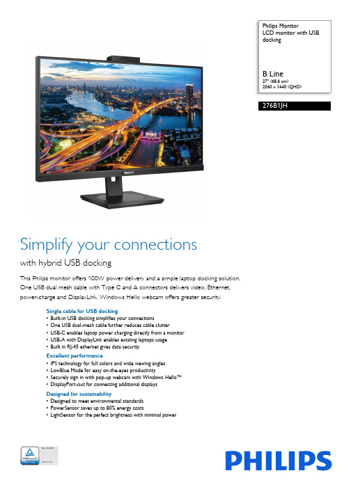
Philips 276B1JH 27英寸 LCD 显示器说明书
Philips MonitorLCD monitor with USBdocking ArrayB Line27" (68.6 cm)2560 x 1440 (QHD)276B1JHSimplify your connectionswith hybrid USB dockingThis Philips monitor offers 100W power delivery and a simple laptop docking solution.One USB dual mesh cable with Type C and A connectors delivers video, Ethernet,power-charge and DisplayLink. Windows Hello webcam offers greater security.Single cable for USB docking•Built-in USB docking simplifies your connections•One USB dual-mesh cable further reduces cable clutter•USB-C enables laptop power charging directly from a monitor•USB-A with DisplayLink enables existing laptops usage•Built in RJ-45 ethernet gives data securityExcellent performance•IPS technology for full colors and wide viewing angles•LowBlue Mode for easy on-the-eyes productivity•Securely sign in with pop-up webcam with Windows Hello™•DisplayPort-out for connecting additional displaysDesigned for sustainability•Designed to meet environmental standards•PowerSensor saves up to 80% energy costs•LightSensor for the perfect brightness with minimal powerHighlightsUSB DockingPhilips USB-docking monitors deliver universal port replication, for a simple, clutter-free, notebook connection. Securely connect to networks, transmit data, video and audio from laptop only using a single USB cable. Even more, dock with USB Type-C port for extra power charging. For docking monitors with built-in DisplayLink Technology, users can benefit from forward and backwardcompatibility of USB with virtually any latest notebook. USB-docking can boost business productivity and reduce costs.USB Type-C connectionThis Philips display features a built-in USB type-C docking station with power delivery. With intelligent and flexible power management, you can power charge your compatible* laptop directly. Its slim, reversible USB-C connector allows for easy, one-cable docking. Simplify by connecting all your peripherals like keyboard, mouse and your RJ-45 Ethernet cable to the monitor's docking station. You can watch high resolution video and transfer data at a super-speed, while powering up and re-charging your notebook at the same time.IPS technologyIPS displays use an advanced technology which gives you extra wide viewing angles of 178/178degree, making it possible to view the display from almost any angle - even in 90 degree Pivot mode! Unlike standard TN panels, IPS displays gives you remarkably crisp images with vivid colors, making it ideal not only for Photos, movies and web browsing, but also forprofessional applications which demand color accuracy and consistent brightness at all times.LowBlue ModeStudies have shown that just as ultra-violet rays can cause eye damage, shortwave length blue light rays from LED displays can cause eye damage and affect vision over time. Developed for wellbeing, Philips LowBlue Mode setting uses a smart software technology to reduce harmful shortwave blue light.Windows Hello™ pop-up webcamPhilips' innovative and secure webcam pops up when you need it and securely tucks back into the monitor when you are not using it. The webcam is also equipped with advanced sensors for Windows Hello™ facialrecognition, which conveniently logs you into your Windows devices in less than 2 seconds, 3 times faster than a password.DisplayPort-outWith DisplayPort-out you can connectmultiple high resolution displays with just one cable from your first display to the PC. The ability to daisy chain multiple displays enables you to create a clean desktop without the hassle of too many wires all over.PowerSensorPowerSensor is a built-in 'people sensor' that transmits and receives harmless infrared signals to determine if user is present and automatically reduces monitor brightness when user steps away from the desk, cutting energy costs by up to 80 percent and prolonging monitor lifeLightSensorLightSensor uses a smart sensor to adjust the picture brightness depending on the room light conditions for the perfect picture with minimalpower usage.Issue date 2023-03-23 Version: 2.0.112 NC: 8670 001 85851 EAN: 87 12581 79765 2© 2023 Koninklijke Philips N.V.All Rights reserved.Specifications are subject to change without notice. Trademarks are the property of Koninklijke Philips N.V. or their respective owners.SpecificationsPicture/Display•LCD panel type: IPS technology•Backlight type: W-LED system•Panel Size: 27 inch / 68.6 cm•Display Screen Coating: Anti-Glare, 3H, Haze 25%•Effective viewing area: 596.736 (H) x 335.664 (V)•Aspect ratio: 16:9•Maximum resolution: 2560 x 1440 @ 75 Hz*•Pixel Density: 109 PPI•Response time (typical): 4 ms (Gray to Gray)*•Brightness: 350 cd/m²•Contrast ratio (typical): 1000:1•SmartContrast: 50,000,000:1•Pixel pitch: 0.2331 x 0.2331 mm•Viewing angle: 178º (H) / 178º (V), @ C/R > 10•Flicker-free•Picture enhancement: SmartImage•Display colors: 16.7 M•Color gamut (typical): NTSC 104%*, sRGB 107%*•Scanning Frequency: 30 - 114 kHz (H) / 48 - 75 Hz (V)•sRGB•LowBlue Mode•EasyReadConnectivity•Signal Input: DisplayPort 1.4 x 1, HDMI 1.4 x 1, USB-C x 1 (DP Alt mode, DisplayLink)*•HDCP: HDCP 1.4 (HDMI/DP/USB-C video/ DisplayLink)•HBR3: for USB-C•Signal Output: DisplayPort out*•USB:: Upstream: USB-C 3.2 Gen 1 x 1; Downstream: USB-C x 1 (PD 15W), USB-A 3.2 x 4 (with 1 fast charge B.C 1.2)•Audio (In/Out): Audio out•DCpowerout:x1(****************,max. 90W)*•RJ45: Ethernet LAN up to 1G*, Wake on LAN •Sync Input: Separate SyncUSB•USB-C: Reversible plug connector•Super speed: Data and Video transfer•DP: Built-in Display Port Alt mode•Power delivery: USB PD version 3.0•USB-C max. power delivery: Up to 100 W* (5V/ 3A; 7V/3A; 9V/3A; 10V/3A; 12V/3A; 15V/3A; 20V/ 4.5A)Convenience•Built-in Speakers: 3 W x 2•Built-in webcam: Pop-up 2.0 megapixel FHD camera with microphone and LED indictor (for Windows 10 Hello)•User convenience: SmartImage, Input, PowerSensor, Menu, Power On/Off•Control software: SmartControl•OSD Languages: Brazil Portuguese, Czech, Dutch, English, French, Finnish, German, Greek, Hungarian, Italian, Japanese, Korean, Portuguese, Polish, Russian, Simplified Chinese, Spanish,Swedish, Traditional Chinese, Turkish, Ukrainian•Other convenience: Kensington lock, VESA mount(100x100mm)•Plug & Play Compatibility: DDC/CI, Mac OS X,sRGB, Windows 10 / 8.1 / 8 / 7Stand•Height adjustment: 150 mm•Pivot: -/+ 90 degree•Swivel:-/+180 degree•Tilt: -5 ~ 30 degreePower•ECO mode: 17.6 W (typ.)•On mode: 17.7 W (typ.) (EnergyStar test method)•Standby mode: 0.3 W•Off mode: Zero watts with Zero switch•Power LED indicator: Operation - White, Standbymode- White (blinking)•Power supply: Built-in, 100-240VAC, 50-60HzDimensions•Product with stand(max height): 613 x 537 x225 mm•Product without stand (mm): 613 x 366 x 54 mm•Packaging in mm (WxHxD): 730 x 471 x 193 mmWeight•Product with stand (kg): 7.38 kg•Product without stand (kg): 5.59 kg•Product with packaging (kg): 11.06 kgOperating conditions•Temperature range (operation): 0°C to 40 °C•Temperature range (storage): -20°C to 60 °C•Relative humidity: 20%-80 %•Altitude: Operation: +12,000ft (3,658m), Non-operation: +40,000ft (12,192m)•MTBF (demonstrated): 70,000 hrs (excludedbacklight)Sustainability•Environmental and energy: PowerSensor,LightSensor, EnergyStar 8.0, EPEAT*, TCOCertified Edge, RoHS•Recyclable packaging material: 100 %•Post consumer recycled plastic: 85%•Specific Substances: Mercury free, PVC / BFR freehousingCompliance and standards•Regulatory Approvals: UKRAINIAN, CB, TUV/GS,TUV Ergo, CU-EAC, EAEU RoHS, FCC Class B,ICES-003, CE Mark, TUV Eye Comfort certified,PSBCabinet•Front bezel: Black•Rear cover: Black•Foot:Black•Finish: Texture*"IPS" word mark / trademark and related patents on technologiesbelong to their respective owners.*The maximum resolution works for either USB-C, DP or HDMIinput.*Response time value equal to SmartResponse*NTSC Area based on CIE1976*sRGB Area based on CIE1931*DisplayPort out works only under either DP in or USB-C in.*Mac OS does not support DP-Out MST extension function.*USB-C DP Alt mode means USB-C to C cable, USB-C DisplayLinkmeans USB-C to A cable.****************************************************,max 90W. Only one PC or notebook should be connected to eitherUSB-C or DC out port for power passthrough function)*If your Ethernet connection seems slow, please enter OSD menuand select USB 3.0 or higher version which can support the LANspeed to 1G.*For Video transmission via USB-C, your Notebook/device mustsupport USB-C DP Alt mode*Activities such as screen sharing, on-line streaming video and audioover the Internet can impact your network performance. Yourhardware, network bandwidth and its performance will determineoverall audio and video quality.*For USB-C power and charging function, your Notebook/devicemust support USB-C standard Power Delivery specifications. Pleasecheck with your Notebook user manual or manufacturer for moredetails.*USB-C max. power delivery is upto 100W because of Smart Powerfunction. User can adjust monitor brightness setting to get differentlevels of power delivery. 1st USB-C port can support to 90 W maxand 2nd USB-C port can support to 15 W max. For moreinformation, please refer to user manual.*EPEAT rating is valid only where Philips registers the product. Pleasevisit https:/// for registration status in your country.*The monitor may look different from feature images.。
华天电力 HT5600 双钳多功能接地电阻测试仪使用说明书

声明©2013武汉市华天电力自动化有限责任公司版权所有,保留所有权利。
本使用说明书所提及的商标与名称,均属于其合法注册公司所有。
本使用说明书受著作权保护,所撰写的内容均为公司所有。
本使用说明书所提及的产品规格或相关信息,未经许可,任何单位或个人不得擅自仿制、复制、修改、传播或出版。
本说明书所提到的产品规格和资讯仅供参考,如有内容更新,恕不另行通知。
可随时查阅我公司官网:除非有特殊约定,本说明书仅作为使用指导,本说明书中所有陈述、信息等均不构成任何形式的担保。
服务承诺感谢您使用本公司的产品HT5600双钳多功能接地电阻测试仪。
在初次使用该仪器前,请您详细阅读使用说明书,将可帮助您正确使用该仪器。
我们深信优质、系统、全面、快捷的服务是事业发展的基础。
经过多年的不断探索和进取,我们形成了"以客户为核心、以质量为企业第一生命"的服务理念。
立足现代电测高科技,以更好的产品质量,更完善的售后服务,全力打造技术领先、质量领先、服务领先的知名电测品牌企业。
坚持"用户第一"的原则,构建良好的销售服务体系,为客户提供优质的售前、售后服务!清单导读本说明书装箱清单是标准配置,如有差异请核对供销合同,武汉市华天电力自动化有限责任公司保留修改的权利。
注:详细清单见本说明书最后一页“装箱清单”。
为了避免可能发生的危险,请阅读下列安全注意事项。
本产品只可使用我公司产品专用并且符合本产品规格配套要求的附件。
防止电击和火灾及人身伤害!只有经过专业培训的人员才能操作此仪器/仪表。
为了防止火灾或电击危险,在使用本产品进行试验之前,请务必详细阅读本产品使用说明书,按照产品额定值和标识及满足要求的试验环境进行试验。
使用产品配套的保险丝。
只可使用符合本产品规定类型和额定值的保险丝。
产品输入输出端子、测试柱等均有可能带电压,您在插拔测试线、电源插座时,会产生电火花,务必注意人身安全!试验前,为了防止电击,接地导体必须与真实的接地线相连,确保正确接地。
西继迅达电梯SM5600 V2控制系统说明书调试手册
目录目录 (1)第一章SM 5600串行控制系统功能介绍 (7)1.1. 基本功能列表 (7)1.2. 特殊功能列表 (9)1.3. 安全保护功能列表 (12)1.4. 可选功能列表 (12)第二章SM 5600串行控制系统板类产品型号 (13)2.1. 产品型号命名方法 (13)1. 基本规则 (13)2. 主控电脑板、轿顶电脑板、轿厢电脑板、轿厢扩展板、外呼板命名 (13)2.2. SM5600串行系统板类产品型号列表 (13)第三章SM 5600串行控制系统构成与部件介绍 (14)3.1. 系统结构框图 (14)3.2. 系统主要部件性能指标 (14)3.2.1. 性能特点 (15)3.2.2. 适用范围 (15)3.2.3. 参照标准 (15)3.2.4. 电源规格 (15)3.2.5. 工作温度 (15)3.2.6. 检测指标 (15)3.3. 系统主要部件分类介绍 (16)3.3.1. 主控电脑板SM 5600-V2 (16)3.3.2. 人机交互界面SM5600HMI (19)3.3.3. 轿顶电脑板SM 5600-02A (20)3.3.4. 轿厢电脑板SM 5600-02B (23)3.3.5. 轿厢扩展板SM 5600-02C (25)3.3.6. 外召及显示电脑板SM5600-04A (26)第四章SM 5600串行控制系统的安装 (29)4.1. 重要提示 (29)4.2. 检查 (29)4.3. 系统安装 (29)4.3.1. 安装技术要求 (29)4.3.2. SM 5600系列部件安装 (29)4.3.3. 系统其它部件安装 (30)4.3.4. 控制系统接地 (31)第五章SM 5600串行控制系统参数设置 (32)5.1. 概述 (32)5.2. 系统菜单结构与流程 (33)5.2.1. 主菜单 (34)5.2.2. 通讯状态菜单 (34)5.2.3. 密码校验界面 (34)5.2.4. 监视菜单与参数设置菜单 (34)5.2.5. 菜单设置操作提示 (35)5.3. 监视参数菜单设置与操作 (35)5.3.1. 监视参数表 (35)5.3.2. 设置与操作 (35)1. 选层信息 (35)2. 层站信息 (36)3. 井道开关位置 (36)4. 输入输出 (37)5. 速度反馈 (37)6. 运行记录 (38)7. 故障记录 (38)8. 呼梯测试 (38)9. 输入信号 (39)10. 输出信号 (39)11. 轿厢信号 (39)12. 开/关门输入 (40)13. 通讯测试 (40)14. 软件版本号 (40)5.4. 基本参数菜单设置与操作 (40)5.4.1. 基本参数表 (40)1. 初始步骤 (40)2. 基本参数表 (41)5.4.2. 设置与操作 (41)1. 总楼层数设定 (41)2. 待梯层设定 (42)3. 系统时间设定 (42)4. 自动开门保持时间设定 (42)5. 开门延长时间设定 (42)6. 返基站时间设定 (43)7. 自动开梯时间设定 (43)8. 自动关梯时间设定 (43)9. 消防层设置 (43)10. 锁梯层设定 (43)11. 主控板输入类型 (44)12. 轿顶输入类型 (45)13. 保修时间 (46)14. 层站显示设置 (46)15. 停靠层设置 (46)16. 多段速方式设定 (47)17. 开门延长使能设定 (47)18. 抱闸反馈检测使能设定 (47)19. 开门选择设定 (47)20. 关灯时间 (48)21. F参数 (48)5.5. 运行参数菜单设置与操作 (48)5.5.1. 运行参数表 (48)5.5.2设置与操作 (50)1. 电梯额定速度设定 (50)2. 电机额定转速设定 (50)3. 编码器脉冲数设定 (50)4. 检修运行速度 (50)5. 爬行速度 (51)6. 开门速度 (51)7. 开门超限速度 (51)8. 开门平层速度 (51)9. 单层运行速度 (51)10. 延时开闸 (52)11. 启动速度曲线 (52)12. 抱闸延时 (52)13. 加速斜率A1设定 (52)14. 减速斜率A2设定 (52)15. S时间1——P1设定 (53)16. S时间2——P2设定 (53)17. S时间3——P3设定 (53)18. S时间4——P4设定 (53)19. 零速设置 (53)20. 零速时间 (53)21. 延时抱闸 (54)22. 平层调整 (54)23. 试运行 (54)5.6. 特殊参数菜单设置与操作 (54)5.6.1. 特殊参数表 (54)5.6.2. 设置与操作 (55)1. 开/关门继电器保持时间设定 (55)2. 运行超时时间设定 (55)3. 并联使能设定 (56)4. 群控使能设定 (56)5. 远程监控设定 (56)6. 消防方式 (57)7. 远程梯号 (57)8. 并联梯号设定 (57)9. 恢复出厂值 (57)10. 多段速度值设定 (58)11. 减速距离设定 (60)12. 贯通门 (60)13. 开关门到位检测 (61)14. Inventer (61)5.7. 其它参数菜单设置与操作 (61)5.7.1. 保存参数 (61)5.7.2. 井道自学习 (62)5.7.3. 密码设置 (63)5.7.4. 参数拷贝 (63)第六章SM5600串行控制系统调试与运行 (64)6.1. 重要提示 (64)6.2. 通电前检查 (64)6.3. 通电和检查 (65)6.3.1. 通电前确认 (65)6.3.2. 通电后检查 (65)6.4. 系统参数设定 (66)6.5. 电机参数自学习及原点整定 (66)6.5.1. 富士G11UD(异步)具体步骤 (66)6.5.2. 西威A VY(永磁同步)电机参数自调谐及原点自学习 (66)6.6. 慢车试运行 (67)6.6.1. 机房检修运行 (67)6.6.2. 轿顶及轿厢检修运行 (68)6.7. 井道自学习 (68)6.7.1. 井道自学习前的检查 (68)6.7.2. 井道自学习 (69)6.7.3. 井道自学习故障信息的查看 (69)6.8. 快车试运行 (69)6.9. 轿厢及外呼显示板地址的设定方法 (69)6.10. 终端电阻的跳接及测量 (70)6.11. 多段速设置 (71)6.11.1. 电梯运行控制时序的调整 (71)1. Inverter Type (71)2. 延时开闸 (71)3. 启动运行曲线 (71)4. 抱闸延时 (71)5. 零速设置 (71)6. 零速时间 (71)6.11.2. 多段速方式调整 (71)1. 多段速度值设置 (71)2. 多段速度指令输出逻辑 (72)6.12. 平层精度调整 (72)6.13. 功能测试 (73)6.14. 故障查询 (73)第七章提前开门/再平层 (74)7.1. 提前开门安全电路板(SM5000-05) (74)7.2. 提前开门安全电路板(SM5000-05)原理图 (74)7.3. 提前开门安全电路板(SM5000-05)接口定义 (75)7.4. 提前开门安全电路板(SM5000-05)与主控板的接线图 (75)7.5. 再平层门区感应器及门区感应器的安装方法 (75)7.6. 参数设置 (76)第八章SM5600串行控制系统的并联与群控 (77)8.1. SM5600并联控制的说明 (77)8.1.1. 简述 (77)8.1.2. 并联运行的参数设置及要求 (77)1. 参数的设置 (77)2. 并联接线示意图 (77)3. 并联运行的要求 (78)4. 功能确认 (78)8.2. SGC5000群控系统介绍 (78)8.2.1. SGC5000群控板 (78)8.2.2. SGC5000群控板的基本特点 (78)8.2.3. SGC5000群控电脑板显示信息及端子定义 (79)1. SGC5000群控主板端子定义 (79)2. SGC5000-02群控扩展端子定义 (80)3. SGC5000群控板显示信息 (80)8.2.4. SGC5000接线图 (81)8.2.5. SM5000群控运行的参数设置及要求 (81)第九章SM5600串行控制系统故障分析 (82)9.1. 检修运行条件 (82)9.2. 检修运行速度低、电流大 (82)9.3. 主控电脑板显示的速度不正确 (82)9.4. 通讯不正常检查 (82)9.5. 开关电源(5V/24V)异常 (83)9.6. 没有方向及抱闸输出信号的检查 (83)9.7. 电梯不关门 (83)9.8. 安全回路接触器(KAS)触点状态与线圈状态不一致(ER02) (84)9.9. KMY接触器输出与反馈结果不一致(ER04) (84)9.10. 抱闸接触器检测故障(ER05) (84)9.11. 脉冲数过少或A、B方向错误(ER11) (84)9.12. 门联锁继电器触点状态与线圈状态不一致(ER16,ER17) (85)9.13. 抱闸反馈检测故障(ER18) (85)9.14. 主控电脑板未收到变频器运行信号反馈(ER21) (85)9.15. 不能快车运行(ER25) (85)9.16. 楼层位置计数器错误(ER28) (85)9.17. 电梯运行方向与指令方向相反(ER30) (85)9.18. 低速度换速距离大于单层间距(ER41) (86)附录 (87)附录1. 同步电机控制配西威变频连接图与时序图 (87)1. 变频器连接图 (87)2. SM5600+西威时序图 (88)附录2. 同步电机控制配CT变频连接图与时序图 (89)1. 变频器连接图 (89)2. SM5600+CT时序图 (90)附录3. 系统故障代码表 (91)附录4. 自学习故障代码表 (98)附录5. 层站显示字符表 (100)第一章SM 5600串行控制系统功能介绍1.1. 基本功能列表外呼显示“”后,按慢上或慢下按钮,电梯会以检修速1.2. 特殊功能列表1.3. 安全保护功能列表1.4. 可选功能列表第二章 SM 5600串行控制系统板类产品型号2.1. 产品型号命名方法1. 基本规则SM 5600—□□2. 主控电脑板、轿顶电脑板、轿厢电脑板、轿厢扩展板、外呼板命名⑴主控电脑板: SM 5600-V2⑵轿顶电脑板: SM 5600-02A -V2 ⑶轿厢通信板: SM 5600-02B -V2 ⑷轿厢扩展板: SM 5600-02C ⑸外呼板: SM 5600-04A ⑹提前开门板: SM 5000-05 ⑺其它请参见产品型号列表。
Philips 5600系列LED背光源智能电视产品说明书

请至以下互联网址注册产品以获得完整的信息服务快速使用指南使用产品前请阅读用户手册(具体操作详见操作导引)并请保留备用!5600系列LED背光源智能电视43PFF5657/T350PFF5657/T350PFF5659/T343PFF5659/T3产品外形根据型号不同会有所差异,请以实际机型为准!目录重要信息 3包装清单 5电池安装方式 6安装底座 7连接 8打开电视 12操作导引 13中国电子信息产品污染控制标识要求 15重要信息安全小心触电或发生火灾!• 切勿让电视机与雨或水接触。
切勿将液体容器(例如花瓶)放置在电视机旁边或上面。
如果将液体洒到了电视机表面或内部,请立即断开电视机的电源。
请与Philips 客户服务中心联系,对电视机进行检查后再行使用。
• 切勿将电视机、遥控器或电池放在明火或其它热源(包括直射的阳光)附近。
为避免火焰蔓延,请始终使蜡烛或其它明火远离电视机、遥控器和电池。
• 切勿向电视机上的通风槽或其它开口中插入任何物体。
• 旋转电视机时,请确保电源线不会绷紧。
电源线绷紧会使电源连接变松,进而产生火花。
小心短路或起火!• 切勿将遥控器或电池暴露在雨中、水中或过热的环境中。
• 请避免电源插头产生拉力。
松动的电源插头可能产生火花或者导致起火。
小心人身伤害或电视机损坏!• 需由两个人搬运重量超过25千克的电视机。
• 将电视机安装在机座上时,请仅使用提供的机座。
将机座牢固地固定到电视机上。
将电视机放在水平、平坦且可承受电视机和机座总重量的表面上。
• 采用壁挂方式安装电视时,请仅使用可承受电视机重量的壁挂安装托架。
将壁挂安装托架固定到可承受电视机和壁挂安装托架总重量的墙壁上。
TPV Display Technology(Xiamen)Co.,Ltd.对由于安装不当而造成的事故、人身伤害或损失不负任何责任。
小心伤害儿童!请遵循以下注意事项,以避免因电视机掉落而导致儿童受伤:• 切勿将电视机放在由可拉动的布或其它材料覆盖的表面上。
Philips LCD Monitor 电子用户手册.pdf_1718559405.4528391说
Safety and Troubleshooting Information•安全措施及维修• 常见问题• 故障检修• 有关规定• 其他相关信息安全和故障检修安全措施与维修警告:使用本文件规定以外的控制、调整或程序,可能导致遭受电击、触电以及/或者机械危险。
连接和使用电脑显示器时,请阅读并遵循以下说明:操作:● 不要让显示器受阳光直接照射,并使其远离火炉或其它任何热源。
● 移开任何可能掉入通风孔的物品或者会妨碍显示器电子器件正常冷却的物品。
● 不要堵塞机壳上的通风孔。
● 放置显示器时,确保电源插头和插座便于插拔。
● 如果通过拔掉电源线或直流电源线关闭显示器电源,则在重新连接电源线或直流电源线以进行正常操作之前,必须等待 6 秒钟。
● 请务必使用由 Philips 提供的经过认可的电源线。
如果电源线缺失,请与您当地的服务中心联系。
(请参见“消费者信息中心”)● 在使用过程中,不要让 LCD 显示器遭受剧烈震动或冲击。
● 在使用或运输期间,不要敲打显示器或使显示器掉落。
维护:● 为保护显示器不受破坏,不要过分用力按压 LCD 面板。
移动显示器时,抓住边框将其抬起;抬起时,不要将手或手指放在 LCD 面板上。
● 长时间不使用显示器时,应拔掉显示器电源插头。
● 使用略微蘸湿的布清洁显示器时,应拔掉显示器电源线插头。
电源关闭时,可以使用干布擦拭屏幕。
但是,切勿使用有机溶剂(如酒精)或含氨水的液体清洁显示器。
● 为避免电击或本机永久性损坏,不要在多尘、下雨、水附近或过分潮湿的环境中使用显示器。
● 如果显示器被弄湿了,应尽快用软布擦拭干净。
● 如果异物或水进入显示器,请立即关闭电源,并拔掉电源线。
然后,取出异物或擦干水,并送到维修中心进行检修。
● 不要在靠近热源、阳光直射或过分寒冷的场所存放或使用 LCD 显示器。
● 为了保持显示器的最佳性能并延长使用寿命,请在符合下列温度和湿度条件的地方使用显示器。
r温度:5-35°C 41-95°Fr湿度:20-80% RHfile:///D|/My%20Documents/dfu/200W6/china/200w6/safety/safety.htm (1 of 2)2005-06-28 1:56:10 PMSafety and Troubleshooting Information维修:● 只有专业的维修人士可以打开机壳盖。
5600_5600SE_中文操作手册
b、 产水量设定 按动 Up 或 Down 键可以设定软水器再生前的产水量; c、 再生时间设定 按动 Extra Cycle 键,程序进入再生时间设定,通过按动 Up 或 Down
RINSE)、盐箱注水(BRINE REFILL)。
调试工作
1、 调整控制器到工作位置,让水流进树脂罐,当水流停止时,打开阀门以放尽罐中空气, 然后关闭;
2、 插上电源,观察是否工作; 3、 控制器时间设定 按动 Up 或 Down 键可调整时间,连续按住可连续调整; 4、 控制器简单编程(控制器时间非 12:01PM)
8、盐箱充水
硬水经控制器进水口,向下通过树脂 层,然后向下流过下布水器、中心管, 最后通过排水口流出。
硬水经控制器进水口,经过射流器、盐阀、 流量控制板给盐箱充水,同时硬水流过阀 体凹槽向下经过树脂层,被软化后进入布 水器、中心管,最后通过出水口流出。
5
5600 5600SE 中文操作手册
设备的安装和运行
(PRELIMINARY RINSE)、反洗(BACKWASH)、吸盐与慢洗(BRINE & SLOW RINSE)、快洗 (RAPID RINSE)、稳层清洗(SETTLING RINSE)、盐箱注水(BRINE TANK FILL)。
时间型
流量延时再生型
8
5600 5600SE 中文操作手册
调试工作
7
5600 5600SE 中文操作手册
FLECK5600 控制器(流量型/时间型) 调试步骤
准备工作和注意事项
a、 设备在调试及运行前应按厂家要求安装完毕进、出水、排污管道和阀门; b、 自来水、电源及排水沟准备就绪; c、 打开旁通阀,让自来水冲洗管道至出水变清,然后关闭阀门; d、 控制器手动再生旋钮只可顺时针旋转,相应位置分别为:工作(SERVICE)、预清洗
JC-5600使用手册
系统软件说明书一简介JC-5600模拟集成电路测试系统控制软件是在WindowsXP环境下,利用Visual C++ 6.0作为系统开发工具开发的集成测试管理系统。
测试系统软件包括:测试处理、测试数据显示、数据统计、测试程序管理、测试程序框架自动生成、多种功能集成在一起。
提供操作方便的用户界面,使用者通过菜单、工具条,快捷键等操作程序。
不需要对C++的编写方法有很深的了解,系统自动生成测试程序框架,并提供专用的测试函数。
测试程序开发人员只需编写测试过程,显示、统计等功能系统自动处理,不需要用户再次开发,提高测试程序的开发效率。
二软件安装1.文件构成说明User ――――――――存放用户测试程序的默认目录Include ――――――――存放 .h头文件目录Library ――――――――存放 .lib 文件目录Califile ――――――――存放校准数据,自检结果目录JC5600.exe ――――――――测试管理系统执行主程序comm3196A.dll ――――――――测试程序专用函数库datalog.dll ――――――――测试数据接口库*.dat ――――――――系统数据文件*.Sum ――――――――保存统计数据文件*.dlg ――――――――保存测试数据文件(Txt)*.prg ――――――――测试程序设置文件*.prgtmp ――――――――测试程序设置文件备份,用于在乒乓测试环境,自动产生。
*.csv ――――――――保存测试数据文件(Excel)2.安装软件将光盘中JC3196DX-Ⅱ目录拷贝到D:\下,目录名必需为JC3196DX-Ⅱ。
3.VC++6.0 设置在JC-5600模拟集成电路测试系统上开发的测试程序是在Microsoft Visual C++6.0 环境下开发。
因此,必须安装Microsoft Visual C++6.0。
安装方法,参照Microsoft Visual C++6.0的安装向导自动进行安装。
- 1、下载文档前请自行甄别文档内容的完整性,平台不提供额外的编辑、内容补充、找答案等附加服务。
- 2、"仅部分预览"的文档,不可在线预览部分如存在完整性等问题,可反馈申请退款(可完整预览的文档不适用该条件!)。
- 3、如文档侵犯您的权益,请联系客服反馈,我们会尽快为您处理(人工客服工作时间:9:00-18:30)。
目录中央控制系统使用说明 目录1、简介--------------------------------------------------------12、重要注意事项---------------------------------------------12.1、安全注意事项------------------------------------------12.2、使用注意事项------------------------------------------13、主机前面板简介------------------------------------------24、控制面板功能说明---------------------------------------25、主控机的系统连接图------------------------------------46、系统连接说明-------------------------------------------- 36.1、音视频输入连接--------------------------------------- 36.2、音视频输出连接---------------------------------------36.3、VGA 信号端的连接-------------------------------------36.4、控制端口的连接---------------------------------------36.4.1、控制面板的连接------------------------------------ 36.4.2、单机串口通讯的连接------------------------------ 36.4.3、网络控制模式(备选功能)连接---------------- 36.4.4、投影机RS232控制的连接-------------------------- 56.5、红外发射头的连接------------------------------------使用说明书多媒体中央控制系统中央控制系统使用说明 第 1 页 共 12页11、VCD (或DVD )、多媒体PC 机等现代化电教设备。
主讲人员操作这些设备时将会同时用到多种遥控器,频繁的换取遥控器导致极为不便。
使用本多媒体中央控制系统,可将以上各种控制全由主机来完成,主讲人员只需操作主机即可轻松自如地控制这些设备乃至音响、灯光、空调、窗帘等,还可更方便地使用一只专为主机设计的遥控器来遥控主机完成所有功能。
用户也可以通过操作电脑键盘、鼠标、触摸屏、PC 遥控器、本机配备的薄膜开关控制面板等让主机间接地控制各种家电设备。
例如让主机打开课室内的DVD 机、录像机播放指定节目或倒带、暂停、录像等,满足了使用者的特定需要,让使用者充分体会和享受到了高科技电子教学设备所带来的便捷和无穷乐趣简介2、重要注意事项为了避免出现错误的使用及操作,请在使用本产品前认真阅读本手册并注意以下事项:★2.1安全注意事项2.1.1、正确使用电源,通电前必须保证所有与中控主机的输入输出端口相连接的设备之间的地线连接良好。
2.1.2、应使用带有接地装置的三芯电源插座,并应确保电源插座接地正确可靠。
2.1.3、请使用主机标注的电源电压,如不能确定电源有效值,请与经销商及电力公司联系。
2.1.4、在雷雨天或长期不使用本产品时,请拔掉电源插头,断开电源,并做好防潮防尘措施。
2.1.5、按以下方法插拔电源插头或防止电火花的产生。
■不要将插头插在污脏的插座上■将插头插在插座上时应确保牢固可靠,不应有松动。
2.1.6、切勿靠近高温或潮湿、有酸碱性等腐蚀性气体、多尘 震动的环境下存放和使用。
2.1.7、清洗前请拔下电源插头并用软布轻拭,切勿使用有机或稀释剂等腐蚀性清洁剂。
2.1.8、切勿擅自拆开并维修本设备,更不要试图将任何物体塞入机内。
需要时应找合格的技术维修人员维修。
★2.2、 使用注意事项2.2.1、请将中控主机及控制面板放在平稳牢固的桌子或台面。
2.2.2、不要在主机上堆放重物。
2.2.3、使用本机时不要将其放沙发、地毯或其它软面上,除非有良好的通风措施,以免机器过热。
2.2.4、停电或移动时,请拔掉插头,断开电源,以确保人员和机器的安全。
2.2.5、发生以下情况时,请拔掉电源插头断开电源,并与服务中心联系: ■电源插头已坏或磨损■机内溅入液体或遭雨水淋浸■当按使用说明书所指示而不能正常操作,或得不到规定的控制效果。
2中央控制系统使用说明 第 2 页 共 12页3、主机前面板简介①.电源指示②.操作指示③.学码指示④.红外接收接通电源时亮主机通讯正常时会闪亮在红外代码学习录入时,以亮、闪亮等形式表示红外录码在红外线代码学习录入进时,接收来自遥控器的信号4、控制面板功能说明图 1图 2 控制面板示意图 控制面板采用9针串口线与主控机的“控制面板”接口相连(包装中带有原装线)。
共用功能键中央控制系统使用说明 第 4 页 共 12 页4LENOVO图3 主机的系统连接图接中央控制系统使用说明 第 3 页 共 12 页4.1,系统ON :开启中央控制系统。
4.2,系统OFF : 关闭中央控制系统。
4.3,幕开/停:按下此键,则打开电动降升电源,使电动幕升起。
再次按下此键时,电动幕停止动作。
4.4,幕降/停:按下此键,则打开电动幕降电源,使电动幕下降。
再次按下此键时,电动幕停止动作。
4.5,台式电脑:将台式电脑的VGA 图像输出到投影机,音频输出到功放及预视音频输出端。
4.6,手提电脑:将手提电脑的VGA 图像输出到投影机,音频输出到功放及预视音频输出端。
4.7,录像机:将录像视频输出到投影和预视端,音频输出到功放及预视音频输出端。
同时将共用功能按健转归录像机使用.4.8,展台:将展台视频输出到投影和预视端,音频输出到功放及预视音频输出端;同时将数码展台的VGA 输出信号输出到投影机。
4.9,影碟/电视:将影碟机(如DVD )或电视的视频信号输出到投影和预视端,音频输出到功放及预视音频输出端。
同时将共用功能按健转归影碟机使用。
4.10,卡座:将卡座的音频信号输出到功放及预视音频输出端;同时将共用功能按健转归卡座使用。
4.11,开机:按此键使主机产生开启投影机的控制码,并传送给主机的红外发射或RS232控制发送系统控制投影机开机。
RS2324.13,视频:按下此键,投影机将显示从视频端口输入的信号。
4.14,电脑:按下此键,投影机将显示从电脑端口输入的信号。
4.15,话筒音量+/- :增加或减小话筒音量。
4.16,总音量+/- :增加或减小系统的音量。
35、系统连接说明主控机的系统连接参见图35.1、音视频输入的连接:用双端AV莲花插头线将DVD、展台、卡座等设备的音视频输出端与主控机相连接;用双端立体声耳机插头线将电脑的音频输出端与主控机的电脑音频输入端相连接(本机只配备了一条电脑音频连接线,用户如要连接手提电脑音频输出则需另外购买一条相同的连接线)。
5.2、音视频输出的连接:把主控机的音频输出端口按左右通道分别用双端AV 莲花插头线与功放的音频输入端相连接;另一组音频输出端口可与其它预监设备(如电视机)的音频输入端相连接。
把视频输出分别连接到投影机和预监设备的视频输入口;5.3、VGA信号端的连接5.3.1、用通用15针TB头VGA线(两端为针)把台式电脑、手提电脑、数码展台、 具备VGA输出的DVD的VGA输出端与主控机的相应输入端相连接。
5.3.2、主控机VGA输出端口分别接至电脑显示器和投影机。
中央控制系统使用说明 第 6 页 共12 页66、红外控制功能说明:主控机对各设备的控制一般采用红外控制方式(对投影机等具有RS232串口通讯功能的设备多采用RS232控制方式),控制前必须把各个设备的各种红外代码正确学习录入主控机。
学码有两种方法:通过控制面板学码和通过系统软件学码。
6.1、控制面板学码 步骤和方法如下:6.1.1、按住控制面板上的“幕降/停”约6秒钟,直到主机前面板上的学码指示灯,设备灯(,参见图1,图2)亮后即松开;6.1.2、此时表示主控机已进入学码状态,现在我们以投影机为例,按一下设备键(台式电脑)后,台式电脑状态灯亮,主控机学码指示灯亮。
即表示可进入该设备相应操作功能的读码。
注意:对投影机控制键(“开机”、“关机”)进行红外读码时,应切换到“台式电脑”处。
6.1.3示灯亮.表示主机已准备好读入该功能码,再用所选设备的遥控器对准读码窗按一下相对应的功能键,如主控机操作指示灯灭,学码指示灯闪一下.即表示主机已接收到遥控码。
注:主控机准备接收功能键红外码的等待时间不能太长(约10 秒),否则操作指示灯会自动熄灭。
此时发码,主控机也接收不到,须重复6.1.3。
6.1.4、重复6.1.3操作,把所选设备的其它在控制面板上的功能键的遥控码读入。
6.1.5、如要退出当前设备的读码状态并保存录入的红外码,必须按住“幕降/停”直到主机前面板上的红外状态灯(学码指示灯)熄灭。
6.1.6、重复6.1.1—6.1.5的操作完成其它设备在控制面板上的读码。
6、软件学码 控制面板学码时,因面板上的按键数量有限,不能完全输入设备的各种功能按键的红外码。
如使用主控电脑配合系统自带的控制软件进行学码,则可解决此问题。
学码前把主控电脑与主控机使用系统自配的RS232串口通讯线相连接(相关设置具体见第八节“RS232控制功能说明”),打开主控机电源,然后开主控电脑,打开系统软件程序(假设系统软件已装入主控电脑)并用光标点击程序界面左上角的.25中央控制系统使用说明 第 5 页 共 12 页 5.4、控制端口的连接5.4.1、控制面板:把控制面板连接到主机“控制面板”端口。
5.4.2单机串口通讯控制:如非网络模式控制时,直接用本机配备的1.5米长串口线(9针DB头,一端为针,另一端为孔)把控制电脑与主机相连接,为针的一端接主控机,为孔的一端接电脑;5.4.3、网络控制模式(备选功能):如需要采用网络控制模式时,则应将网线接入本机的网络接口。
5.4.4、投影机RS232控制的连接:主控机上“投影机RS232控制”端口为9孔DB头,其3脚为信号发射端,连接时对应接投影机RS232控制口的接收脚“RX D”;5脚为接地端对应接投影机RS232控制口的“GND”接地端。
一般投影机RS232控制端口分为几种,有DB9、PS/2、DB15等几种。
其脚位图可在投影机说明书或资料中查到。
5.5、红外发射头的连接:本系统所配备的4只红外发射头已配接了插头和连线,用户只需直接把发射头的插头分别插入A1—A4口即可;为保证接收可靠,用户应把发射头对准设备的红外接收头并用胶带粘牢,如图4所示。
