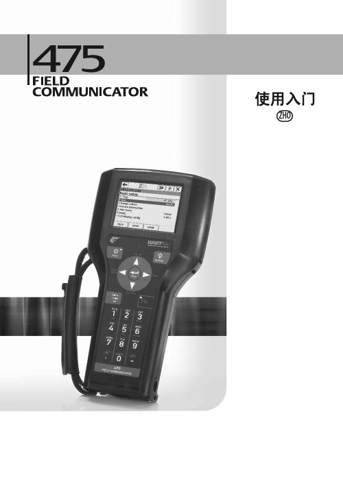
HART475手操器说明书
HART475手操器教程
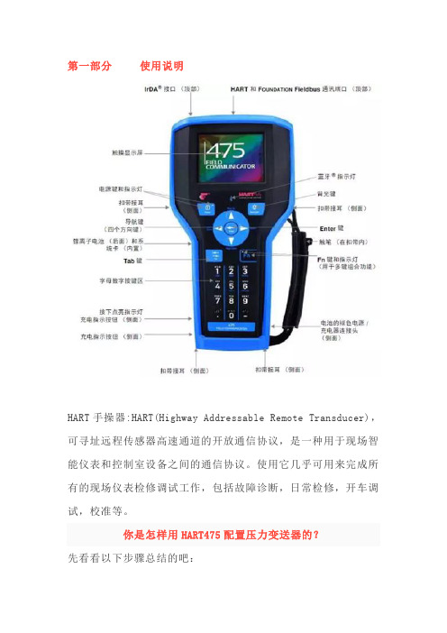
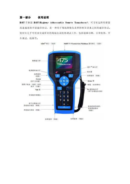
第一部分使用说明HART手操器:HART(Highway Addressable Remote Transducer),可寻址远程传感器高速通道的开放通信协议,是一种用于现场智能仪表和控制室设备之间的通信协议。
使用它几乎可用来完成所有的现场仪表检修调试工作,包括故障诊断,日常检修,开车调试,校准等。
你是怎样用HART475配置压力变送器的?先看看以下步骤总结的吧:1.开机,将手操器与仪表连接,选择HART2.通讯成功以后,选择Online(在线)当出现以下文字时,不要慌张,点YES就行3.具体操作,以川仪(EJA)为例。
改量程改位号、改单位回路测试(打点)调零点PS:在更改完数据后要选“SEND”发送给变送器HART475图形图像都说明了啥现场通讯器屏幕布局常用按钮使用下列按钮,可修改窗口上曲线图和图表的(以艾默生HART475为例)平移,触击按钮,选择图表或曲线图中的一点,拖动此点在窗口中反复地移动。
区域缩放,触击按钮,然后触击并拖动图表中的一点来创建放大的方框。
当您从窗口释放触笔后,图表将放大并适应此区域。
此控件仅可用于条形图表和曲线图。
放大,触击此按钮,从图表中心以固定比率放大。
再次触击,重复此操作。
缩小,触击此按钮,从图表中心以固定比率缩小。
再次触击,重复此操作。
重置,触击按钮,将图表或曲线图返回至原始主屏幕,取消您执行的任何平移或缩放操作。
下拉列表,触击此菜单,在不同的变量中选择,在图表上或曲线图的不同波形中高亮显示。
图形选项图像图像是设备的全屏幕照片。
图像可包含标识和多种图形,如容器。
要查看图像,选择菜单中的图像或绘图标签。
显示全屏幕图像。
要返回菜单视图,按任何键或触击触摸屏。
一些图像具有链接,可以运行方法或查看附加菜单。
如果图像具有链接,将在菜单中的图像或绘图标记旁出现箭头。
当打开图像后,使用向左键返回菜单、或按任意键启动方法或与图像或图纸关联的附加菜单。
如果链接未与图像关联,按任意键返回菜单。
HART475中文说明书
HART通信器是一种便携式的终端,它与采用HART通信协议的仪表一起使用,对其进行设定,更改和显示,它可监控输入/输出值和自诊断结果。
设定恒定电流的输出和调零。
当系统开动或维持操作时,只要把HART通信器接在4~20mA通信信号线上,就可以使用。
特点:■ 在线监控和通信通信期间,调制信号不会中断4~20mA DC信号■ 与采用HART通信协议的仪表可共用HART通信器能与采用HART通信协议的所有仪表一起使用■ 操作方便大显示屏幕(4行,每行18个字符),采用中文显示,用户看了一目了然,设定和更改方便■ 信息自诊断/保护功能自检查功能格式化密码保护低电压报警显示标准技术规格:装置的技术规格适用仪表:ROSEMOUNT1151 , ROSEMOUNT3051ABB日本富士YOKOGAWA EJA(带HART通信协议)等进口压力变送器DS-1151,DS-3351HK1151 , HK3151等国产智能压力变送器通信信号的连接:专用线缆,长1.1m(3.6ft)通信线:长度:1Km(0.62英里)(0.75~1.25mm2)负载电阻:250~600Ω负载电容:0.22uF以下负载电感:3.3mH以下与电源线的间距:15cm以上(避免平行走线)显示:128*64点阵液晶显示控制:触摸开关(4个方向键,19个功能键,一个电源开关)电源:4支1.2V可充电电池尺寸:180*80*54mm (长*宽*高)重量:700g功能说明基本功能:■ 设定、更改和显示各种参数,HART通信■ 恒定电流输出■ 调零附加功能:■ 格式化保护需要输入密码才能进行格式化■ 电池报警LCD显示的报警信息可提示电池电压偏低■ LCD对比度调节正常工作条件环境温度: -15~55℃存储条件:环境温度:0~50℃附件:■ 通信电缆:壹根,分别带一个弹簧夹。
■ 4只1.5V电池■ 手提包■ 说明书■ 250偶坶电阻EMC认可标准:EMI(辐射)—EN55011:1991hart475手操器 Rosemount罗斯蒙特HART475手操器 产品介绍 hart475手操器通讯器,艾默生过程管理的新型的475现场通讯器,是罗斯蒙特hart375手操器的改良升级型号,它即支持HART 通讯协议,也支持基金会现场总线通讯协议,并具有通用、可靠、便携、本安、易于升级等特点。
HART475手操器说明书(彩屏款)
目录第一节简介2第二节基本使用2安装电池组2启动和关闭2启动通信器3关闭3基本性能和功能3键区的使用4第三节电气连接方式5建立HART回路连接5查看在线菜单7第一节简介本仪表适合HART协议的智能变送器以及各类HART标准协议的流量仪表的通信操作,与HART275、HART375、HART475兼容,可通信1151,3051,EJA,ABB及其他HART协议的进口仪表,完全兼容国产的各种智能压力变送器以及带有HART协议的智能流量仪表。
第二节基本使用安装电池组1.将现场通信器正面朝下放在平稳的表面上。
2.按住电池后盖开关,将其推向■的一边打开后盖开关,将后盖揭开装进电池,当电池装好后再将后盖开关推向■的一边锁上开关。
(注意在揭开后盖时从缝隙处轻轻揭开,以免损坏后盖)启动和关闭该通信器使用5节5号干电池,使用前请确保:1.该通信器没有损坏2.电池组已安装好3.所有螺丝没有松动4.将通信器连接到回路,参见第三节:建立HART回路连接启动通信器按住开/关键,直到液晶屏点亮,表明装置已经工作。
开/关键位置可参见图2-1。
在启动期间,通信器将自动轮询检测HART回路设备,如果连接正常将显示被连接设备工位号及进入主菜单,您可以进行以下选择:关闭按住“开关”键半秒钟以上,松开按键,关机完成。
键区的使用开关键箭头导航键四个箭头导航键可便于您在菜单栏中移动,选择,进入或退出。
按右箭头导航键()可进入下一级菜单(同Enter 键),在操作界面为“确认”键功能或数据发送功能,对应屏幕显示右侧字符所表示的功能。
按左箭头导航键(口)可返回上一级菜单,在操作界面为“返回”或“取消”键功能,对应屏幕显示左侧字符所表示的功能。
在输入界面基本性能和功能HART 现场通讯接口液晶显示屏字母数字键区图2-1通讯器示意图① Power)用于现场通信器的启动或关闭。
JKL斗STLL开关键四个方向导航键所DawirrtdnlG4lfl r液晶背光B-^rtWFFDK时按下键为删除功能。
HART475手操器英文说明书

FIELD COMMUNICATORJIANGSU BOOST INSTRUMENT SCIENCE AND TECHNOLOGY CO.,LTDCHAPTER Ⅰ Introduction (2)CHAPTER Ⅱ Basic use (3)2.1 Field communicator basic performance and functions (3)2.2 Power Considerations (4)2.3 Key areas of use and instructions (5)CHAPTER Ⅲ menu online operation3.1 Test menu (6)3.1.1 Always poll (6)3.1.2 Ask before polling (7)3.1.3 Select the type (7)3.2 PRESS TRANS MAIN MENU (8)3.2.1 Process variables (8)3.2.2 Diagnostics and service (9)3.2.3 Characterization (11)3.2.4 Calibration (17)3.2.5 Display mode (19)3.2.6 General format (20)3.3 ELECTROMAGNETIC FLOWMETER MAIN MENU (20)3.4 VORTEX FLOWMETER MAIN MENU (20)3.5 FARGET FLOWMETER/ FLOAT LEV GAUGE MAIN MENU (20)3.6 METAL ROTAMETER MAIN MENU (20)3.7 GENERAL MAIN MENU (21)CHAPTER Ⅳ Troubleshooting (21)4.1 Description and remedy fault (21)4.2 Windows for warning (22)Appendix I (24)Appendix II (25)Appendix Ⅲ (31)CONTENTSCHAPTER Ⅰ IntroductionThank you for using HART475 Field Communicator, Communicator for the HART Communication protocol smart transmitter operation, and HART275, HART375,HART475 compatible with excellent compatibility, communication 1151,3051,EJA, ABB and flow aspects of the HART protocol imported instruments. Completely and yung made a variety of smart transmitters.The manual describes the basic use of field communication device, connection and operation in Content as well as troubleshooting and in the course should pay attention.Field Communicator using the HART475, please read the manual, In order to better play to the best performance of the product in use or maintenance of the product Before understanding of the appropriate content.Should the equipment needs repair, please contact our company. We will do our best to for you.The device is equipped with:a manual operatorBattery aPack aA chargerA communication cableManual aA 250 ohm resistorCHAPTER Ⅱ Basic use2.1 Field communicator basic performance and functionsCommunicatecableBatterydisplayDisplayFourkeysnavigationPV KeyEnterON/OFFAlphanumeric keypadCharger connectorLeft -right selectionkeyField Communicator2.2 Power ConsiderationsIn turn, ensure the following:* The Field Communicator is no mechanical damage* Battery is fully charged.* The Field Communicator to connect to the circuit (Figure 2-2) * String loop resistance of 250 ohms+··Power —+-Figure 2-2Start Field CommunicatorBefore starting to ensure that the device is fully charged. Start holding down the power key until To the bright LCD screen, a successful boot.CloseSuch as to close the Field Communicator, hold the key to open up their show off, shutdown complete.2.3 Key areas of use and instructionsOpen keyThe key is used to enable or disable the Field Communicator. Arrow navigation keysFour navigation arrow keys provide menu options. Press the right arrow navigation key to enter a menu of specific options. Press Left navigation key to return to the previous menu, up and down navigation keys can be cut down in the menu Change. In the character input mode digital down navigation keys can be used as a backspace key. EnterAfter entering the menu, you can modify the contents of the LCD's bottom Line will automatically display the "Edit" to modify the words For you press the Enter key, the change was successful.Alphanumeric keyboardCharacter numeric keypad to enter characters, numbers and other symbols, numbers, and he has Characters in both input modes, field communication device according to the need to select the appropriate input mode.To enter numbers, press the number directly to where the keys to enter characters, according to the word Character position on the keyboard, first pressA key, then press the characterkey is located. For example, to enter the character "A", the first Press the left selection key, then press the number 1 character keyboard.PV keyMonitoring real-time variable shortcuts, view real-time pressure, current, percentage, Temperature, frequency and other real-time variable. Digital input mode, the character, the key is invalid.CHAPTER Ⅲ menu online operation3.1 Detection menuHow to poll:2.Ask Bef PollFigure 3-13.1.1 Polling DetectionSelect the menu, Field Communicator polling numbers from the polling numbers from 0 to 15 followed by detection equipment, if detected, the device will automatically detect the transmitter and the station number(Figure 3-1-1), press the right navigation key to enter the device type selection menu (Figure3-1-2); if not Have detected the device does not detect the transmitter will appear warning.TRANS detected:TAG No[DS8001]Figure 3-1-13.1.2 Detection by poll numbersSpecified number of polling devices to detect, according to the up and down navigation keys Choose between 0 to 15 polling numbers, then press the right navigation key to start the test (test results If the same as Figure 3-1-1).3.1.3 Select Device Type1. Pressure Transmitter2 electromagnetic flowmeter3. Vortex Flowmeter4. Target Flowmeter / float level gauge5. Turn meter gold6 General menuSelect the type:2.Electromagnetic Flow meter3.Vortex Flowmeter4.Target Flowmeter / FloatLEV gauge5.Metal Rotameter6. General MenuWhen choosing the type of equipment must be selected according to the type of field device into a specific menu, if you select the type does not match the actual type, will cause an error. If the site becomes non-pressure equipment, electromagnetic, vortex, target-style, gold transfer device is connected into the general menu. Press the down navigation key to select the device type, then press the right navigation key to enter the selected device type detection, and enter the corresponding menu, if you select the type does not match with the test will be prompted.3.2 Pressure Transmitter Main MenuSubmenu1 Process Variable2 Configuration and testing3 Characterization4 Calibration Main menu:2.DIAG and Service 3.Characterization5 Display Modes6 common formatFigure 3-2-13.2.1 Process VariableReal-time display of pressure transmitter, the percentage of current, temperature and other parameters (Figure 3-2-2). Press the left navigation button for 3 seconds before the bounce out of real-time variable monitoring model.PRESS AO PC –0.2584.8205.127KpamA%TEMP 19.570 ℃3.2.2 Configuration and TestingDIAG and Service 2.Loop Test Submenu:1. Equipment Testing2. Loop test3. Basic Settings4. User range3.Basic setup Figure 3-2-3 3.2.2.1 Test equipmentTesting equipment status, if everything is normal, liquid crystal display "device normal", if wrong, will be a warning.3.2.2.2 Loop TestDetection of the D / A current output. First, a series ammeter in the circuit, and then type a 4-20mA current between the values into the transmitter, the transmitter will automatically output the current value type, if the type of value and ammeter display values are not equal, current fine-tuning to be done.3.2.2.3 Basic SettingsSubmenu:1. Unit2. Write Protect3. DampBasic Setup 2.Write Protect 3.Damping 4. Output5. Device Information6. Polling numbersFigure 3-2-4 UnitChange the primary variable units and display units. Provide MPa, Kpa, Pa, InH2O, InHg, psi, g / cm ², kg / cm ², FtH2O, torr,ATM, mmH2O, mmHg, Bar, mBar these 15 units. When the unit of measure on behalf of the Not recognize the number will automatically display "No" means that the unit "unknow". Repair Change methods, see the menu tree.Write ProtectRead-write device protection status, when the write-protected, the transmitter can not change the internal data. DampRead-write device damping coefficient (rounded to three decimal places). Seconds.OutputRead-write device output. Divided into linear, square root, and the unknown. The default is linear.Device InformationRead and write tag number, date, descriptor, message, final assembly numberPolling numbers3.2.2.4 User rangeUser Range2.Provide pressureFigure 3-2-5Keyboard inputSelect this menu, the first prompt sensor range, then enter the range of the setup menu, press the down navigation key to select zero or range, then enter the user needs to set the value (rounded to three decimal places), then press the right navigation key into the transmitter.Sensor Range L –180.000KPa H 180.000KPa User RangeL –180.000KPa H 180.000KPaFigure 3-2-6 Figure 3-2-7Provide pressure valuesPressure on the current value with the transmitter zero and span settings, press the up and down navigation keys, press the right navigation key to confirm.Provide Pressure2.RangeFigure 3-2-83.2.3 CharacterizationSubmenu:1 .Sensor trim2. Sensor measuring range3 user range4.K coefficient5 Formatting Characterization 2.Sensor range 3.User range6 small-signal removal7 Device Address8. Data Backup9. Data RecoveryThe menu will seriously affect the operation of the transmitter to work and accuracy, so enter this menu, you need to enter the authentication password (Figure 3-2-10).Please input password:******Figure 3-2-10The default password is: 6666663.2.3.1 Sensor trimSensor Trim2.Low Range Trim3.High Range TrimFigure 3-2-11Zero trimAfter the pressure transmitter with 0 to select this operation, the transmitter automatically adjust zero.Low fine-tuningTo increase low-pressure transmitter (in KPa), type the applied pressure values (rounded to three decimal places), thetransmitter automatically corrected, so that the output value of the applied pressure.High-end fine-tuningTo the transmitter plus high pressure (in KPa), type the applied pressure values (rounded to three decimal places), the transmitter automatically corrected, so that the output value of the applied pressure.3.2.3.2 Sensor RangeSensor Range2.Madify rangeFigure 3-2-12Select the rangeFirst select the type of sensor, and then select the range of the sensor code, then press the Enter key into the transmitter. (Figure 3-2-13,3-2-14)Sensor type Range Code[DP ][5]Figure 3-2-14Figure 3-2-13Modify RangeFirst select the range sensor code, then enter the code in the range of the scale. Note: The input pressure is measured in Pa, can only enter a positive integer. Change and then select the sensor range.3.2.3.3 User rangeKeyboard inputSelect this menu, the first prompt sensor range, then enter the range of the setup menu, press the up and down navigation key to select zero or range, then enter the user needs to set the value (rounded to three decimal places), enter and press the right navigation key to send into the transmitter.Sensor Range User RangeL –180.000KPa H 180.000KPa L –180.000KPaH 180.000KPaFigure 3-2-16Figure 3-2-15Provide pressure valuesPressure on the current value with the transmitter zero and span settings, press the up and down navigation keys, the right navigation key to confirm.pressProvide Pressure2.Range3.2.3.4 K factorLow-end need to be done, do high-end.K-factor2.High RangeFigure 3-2-18Low RangeAdd 0 to the pressure transmitter, type 0 in the increase of pressure, press the right navigation key into the transmitter, the transmitter automatically adjust the k-factor low.High RangeAdded to the positive terminal of a pressure transmitter (close to or equal to the physical range), the pressure increases the pressure must be greater than 0, type in the increase of pressure values (rounded to three decimal places, units KPa), press the right navigation key into the transmitter device, the transmitter automatically adjusts the k-factor high.Note: K factors must be operated in positive pressure conditions, and the input unit KPa.3.2.3.5 FormatFull-scale formatNote: This action will seriously affect the accuracy of the transmitter, the user is best not to make their own format.How-to: give added pressure transmitter (pressure points must be positive from the negative pressure up to maximum pressure), then enter the applied pressure (Figure 3-2-19, note: do the negative pressure side formatting , the input pressure to a minus sign in front.), then press the right navigation key to format it, after a successful return to the next point format, an unsuccessful return warning.All of range:01PRESS:[ ]PaFigure 3-2-19InterpolationAfter the ultra-poor calibration point format.Note: This action will seriously affect the accuracy of the transmitter, the user is best not to make their own format.How-to: give added pressure transmitter, and then enter the increase of pressure. (Note: do the formatting in the negative pressure side, the input pressure to a minus sign in front). Press the right navigation key, the interpolation done at this time point measured the pressure should be basically equal to the applied pressure.InterpolationPRESS:[ ]PaFigure 3-2-203.2.3.6 Small-signal removalThis function is to eliminate the zero drift. Enter the number of users than the extreme range.3.2.3.7 Device addressView a device's address. Device address is the unique identification number the smart board.3.2.3.8 Data BackupData backup: the value of the current user scale and format all the data back to FLASH the database, this function is to facilitate data recovery after a mistake. Click the menu "Backup" button3.2.3.9 Data RecoveryData Recovery: The instrument factory, manufacturers have the formatting operation on the instrument, and the correct data formatted to do a backup, misuse of the instrument when the user does not work, you can use the "Data Recovery" function of its error Content removal operation, and re-manufacturers will re-initialize the backup data is written instrument, easy instrument to restore the original data. Click the menu "Data Recovery" button.3.2.4 CalibrationCalibrationSubmenu2.Output Trim1 Sensor trim2 Output TrimFigure 3-2-213.2.4.1 Sensor trimSensor Trim2.Low Range Trim3.High Range TrimZero trimAfter the pressure transmitter with 0 to select this operation, the transmitter automatically adjust zero.Low fine-tuningTo increase low-pressure transmitter (in KPa), type the applied pressure values (rounded to three decimal places), the transmitter automatically corrected, so that the output value of the applied pressure.High-end fine-tuningTo the transmitter plus high pressure (in KPa), type the applied pressure values (rounded to three decimal places), the transmitter automatically corrected, so that the output value of the applied pressure.3.2.4.2 Output TrimOutput fine-tuning needs to be a precision ammeter in series to the circuit, into the fine-tuning, the LCD will prompt access ammeter, the current fine-tuning exit, the LCD will prompt recovery circuit.Warning:Please access circuitammeter!Figure 3-2-234mA current fine-tuningChoose 4mA current fine-tuning, the output should be 4.000mA, if the ammeter shows the value is not equal to 4.000mA, select "No", an input box, type the ammeter showsthe input box value (rounded to three decimal places), then press right navigation key to enter the current value into the transmitter, the transmitter will automatically calibrate the current output, the output of 4.000mA, if a less than satisfactory results, repeat this operation.(Note: The meter accuracy should be higher than the output precision of the table)Output Trim2. Trim DAC GainFigure 3-2-2420mA current fine-tuning4mA current methods of operation and fine-tuning the same. 3.2.5 Display Mode1.%Select this mode, the transmitter displays the percentage.ER SETSelect this mode, the transmitter displays the user settings. ER SET &%Select this mode, the transmitter displays the percentage of user settings and are displayed alternately every 4S.4.INPUT PRESSSelect this mode, the transmitter only the input pressure.5.INPUT PRESS &%Select this mode, the transmitter displays the percentage of input pressure and alternating every 4S.Display Mode2.USER SET3. USER SET&%Figure 3-2-253.2.6 General FormattingGeneral Format: (known as three, five-point format)This menu requires a password to enter the default password is 666666.(1) Select the instrument type and range of code to determine the instrument's physical range.(2) in the common format into the format, the original plate for 1151 current 22mA, the order of the physical range of 0%, 60%, 100% three-point format, or 0%, 60%, 100%, -60%, 100% five-point format. Communication device according to the first line shows the calculation of the percentage range of physical pressure, the pressure and the input Fill pressure (in Pa), right-click until the pressure stabilized first sent.(3) operation is successful, display the percentage of the next point, to continue or exit.Operation failed (such as the pressure increases the pressure and display the corresponding percentage difference too large to return to this point redo. Done 100% in three-point format according to exit after completion of five-point format at 100% done automatically exit. withdrawal of current from 22mA into a measurement of current.3.3 Electromagnetic Flowmeter Main MenuSee photos3.4 Vortex FlowmeterSee photos3.5 Target Flowmeter / float level gaugeSee photos3.6 meter gold transferSee photos3.7 Common main menuSee photosRemarks:The handheld contains vortex flowmeter, the target flowmeter, flow meter gold turn, Common menu and menu operation is similar to the electromagnetic flow meter, this is not setting them in, with Please refer to the distribution of body attached page menu menu tree operation.CHAPTER Ⅳ Troubleshooting4.1 Introduction and troubleshooting faultsIt does not really startIf in the course can not be switched, that can not start the Field Communicator, First check the battery. Should the battery power is still not start, there may be on-site Communication device to open the key is damaged. (Note: Please do not use the process of firm Hard thing to touch the buttons Field Communicator film to avoid damage. )Communication or communications are not interrupted If there is no communication on the first check HART field device loop and voltage. Almost all field devices have at least 4mA and 12VDC to Victoria maintain normal operation.Check the loop impedance, to see whether the access loop 250 ohm external Impedance. Access to 250 ohm resistors, will lead 250 ohm resistor at both ends of the access. And then view the communication is normal.Check the terminal and HART communications cable is damaged.HART communication by the control system interference. At this point stop control system HART communication, recognition and communication between the field device communication.4.2 Tips interfaceLow battery warningWhen the battery voltage is low, top right of the LCD display will flash a battery-shaped pattern.TAG No(DS8001)OnlinePRESS AO0.0064.000KpamAFigure 4-2-1Communication Failure WarningWhen the Field Communicator to the transmitter with the communication failure warning (Figure 4-2-2).Warning:Communication interruption!Check the equipmentFigure 4-2-2Date Input ErrorAllows you to enter a date range January 1, 1900 to December 31, 2155, when the input is not in the range of dates, enter the error message will appear (Figure 4-2-3), note the date input format xxxx xx xx day in May.Date entered incorrectlyFigure 4-2-3Data entry errorsWhen the input parameter is incorrect when the prompt appears, such as the removal of only a small signal input is an integer, if you enter a negative number, an error message will appear (Figure 4-2-4).Entered incorrectly!Appendix I: General menu list of unit typesNo. Unit No. Unit No.3 Unit No.4Unit1 InH2O2 InHg mmH2O mmHg5 9psikg/cm2ATML/S6 barPa7 mbarkPa8 g/cm2torr10141811151912162013 17 L/minm3/sm3/h℃m/smv21 25 29 33Ωm3minv22263034Hzm23273135mAcmh24283236Lmm%spH kg MT37 41 45lb 384246STg/h394347LT 404448g/skg/minlb/s g/minkg/hkg/sMT/min MT/h49 lb/min 50 lb/ h 51 ST/min 52 ST/h53 57 61 65 69 LT/hkg/lL/hKJ5458626670g/cm3g/l5559636771kg/m3m/h5660646872g/mlm3/minKJ/hNm3/hMJ/hMPaNm3/minMJ GJ/h GJ None NoAppendix II: various types of equipment menu tree Pressure Transmitter menu tree:Electromagnetic Flowmeter menu tree:Vortex Flowmeter menu tree:Target Flowmeter / float level gauge menu tree:Gold transfer meter menu tree:Common menu tree:Appendix 3: GlossaryAlphanumericAlphanumeric character set, often including other character sets, such as punctuation marks.Device configurationDefine the physical properties and operating characteristics of the device parameters. Does not include dynamic data.Device DescriptionWritten in the HART Foundation fieldbus devices instruction set, the device description language of the host application and the HART or FOUNDATION fieldbus device communication parameters, and methods of instruction are defined.Field EquipmentIn addition to HART digital communication signal, the field device can generate or receive analog signals.HART devicesUsing the HART protocol for information communication equipment.HART LoopOne communication network, the master and slave devices are HART smart or HART compatible devices.HART protocolAddressing a high-speed remote communications protocol converter. One for the digital add-type 4-20mA communications and intelligent field devices, industry-standard protocols.PollOne kind of query the network in order to determine the method that the device online.。
475手操器使用教程
475手操器使用教程引言:475(HART)手操器是一种用于操作和配置HART(Highway Addressable Remote Transducer)通讯协议的设备。
本文将详细介绍475手操器的使用方法和步骤,帮助读者快速熟悉和掌握该设备。
一、查找设备1.打开475手操器的电源,待其启动完毕后,进入主界面。
2. 在主界面上方,有一个“Find”按钮,点击该按钮进入设备查找模式。
3.在设备查找模式下,手操器会扫描附近的HART设备,当附近有设备可用时,手操器会显示在屏幕上。
如果屏幕上没有显示任何设备,则表示附近没有可用的HART设备。
4.点击手操器屏幕上显示的设备,即可选中该设备。
二、连接设备1. 选中设备后,点击手操器界面下方的“Connect”按钮,手操器将与所选设备建立连接。
2.当手操器与设备成功建立连接后,手操器界面将显示设备的基本信息,如设备名称、设备型号、设备状态等。
三、读取设备参数1.在设备连接成功后,手操器会自动读取设备的基本参数信息,并显示在手操器界面上。
2. 若要读取更多的设备参数信息,可以点击手操器界面上的“Read”按钮。
3.手操器会根据设备的配置,读取相应的参数信息,并显示在手操器界面上。
四、配置设备参数1.在手操器界面上,可以看到设备的各项参数信息。
2.若要修改一些参数,可以点击该参数所在的位置,并输入新的数值。
确保输入正确后,点击确认按钮进行参数修改。
3.在修改参数后,手操器会自动向设备发送新的参数配置命令,设备会根据手操器的配置进行相应的设置。
五、保存配置1.在参数修改完成后,为确保配置的持久性,需要将配置保存到设备中。
2. 点击手操器界面下方的“Save”按钮,手操器会将当前的配置信息保存到设备中,并显示保存成功的提示信息。
六、退出连接1.在配置完成后,需要断开和设备的连接。
2. 点击手操器界面下方的“Disconnect”按钮,手操器将与设备断开连接。
3.在断开连接后,手操器将返回到主界面,准备进行下一次操作。
475手操器中文使用手册
2简介3爆炸可能会导致严重伤害或死亡:在有爆炸危险的环境中使用时,必须遵守相关的本地、国家和国际标准、规范和规程。
请查阅《475型现场通讯器用户手册》中的“参考信息”和“产品认证”部分,以了解有关安全使用的限制规定。
触电可能会导致严重伤害或死亡。
此设备符合 FCC 规范的第 15 部分。
设备操作应符合以下两个条件:(1) 本设备可能不会产生有害干扰,以及 (2) 本设备必须接受任何接收到的干扰,包括可能会导致非预定操作的干扰。
©2009 艾默生过程管理。
保留所有权利。
HART 为 HART 通信基金会的注册商标。
F OUNDATION为现场总线基金会的商标。
IrDA 为红外数据协会的注册商标。
Bluetooth 为 Bluetooth SIG, Inc. 的注册商标。
AMS Suite 为艾默生电气公司的注册商标。
艾默生标志为艾默生电气公司的商标和服务标志。
所有其他商用标志的所有权归其各自的所有者。
简介《475型现场通讯器使用入门指南》提供了 475型现场通讯器的基本操作指南、注意事项和设置信息。
它不包括有关配置、诊断、维护、保养、故障排除或本质安全 (IS) 安装的详细说。
有关更多说明,请参阅资源 CD 里的《475型现场通讯器用户手册》或访问。
475型现场通讯器支持 HART 和 F OUNDATION现场总线设备,使您可以进行现场配置或排除故障。
电子设备描述语言 (EDDL) 技术使得 475型现场通讯器能与大量不同生产商的设备进行通讯。
4475 型现场通讯器概述475 型现场通讯器概述便携式 475 型现场通讯器包括一个彩色 LCD 触摸屏、一块锂离子电池(电源模块)、一个 SH3 处理器、存储组件以及集成通讯与测量电路。
当使用 475 型现场通讯器与设备进行通讯时,请遵守当地适用的所有标准和程序。
不遵守这些标准和程序可能会导致设备损坏和/或人身伤害。
请理解并遵守本手册中的各项内容。
hart475手操器中文说明书
目录第一章简介⋯⋯⋯⋯⋯⋯⋯⋯⋯⋯⋯⋯⋯⋯⋯⋯⋯⋯⋯⋯2第二章基本使用⋯⋯⋯⋯⋯⋯⋯⋯⋯⋯⋯⋯⋯⋯⋯⋯⋯⋯32.1 现场通讯器的基本性能和功能⋯⋯⋯⋯⋯⋯⋯⋯⋯⋯⋯⋯⋯⋯32.2 开机注意事项⋯⋯⋯⋯⋯⋯⋯⋯⋯⋯⋯⋯⋯⋯⋯⋯⋯⋯⋯⋯⋯42.3 键区的使用和说明⋯⋯⋯⋯⋯⋯⋯⋯⋯⋯⋯⋯⋯⋯⋯⋯⋯⋯⋯5第三章在线操作菜单⋯⋯⋯⋯⋯⋯⋯⋯⋯⋯⋯⋯⋯⋯⋯⋯63.1 检测菜单⋯⋯⋯⋯⋯⋯⋯⋯⋯⋯⋯⋯⋯⋯⋯⋯⋯⋯⋯⋯⋯⋯⋯6 3.1.1 轮询检测⋯⋯⋯⋯⋯⋯⋯⋯⋯⋯⋯⋯⋯⋯⋯⋯⋯⋯⋯⋯⋯6 3.1.2 按轮询号检测⋯⋯⋯⋯⋯⋯⋯⋯⋯⋯⋯⋯⋯⋯⋯⋯⋯⋯⋯7 3.1.3 选择设备类型⋯⋯⋯⋯⋯⋯⋯⋯⋯⋯⋯⋯⋯⋯⋯⋯⋯⋯⋯73.2 压力变送器主菜单⋯⋯⋯⋯⋯⋯⋯⋯⋯⋯⋯⋯⋯⋯⋯⋯⋯⋯⋯8 3.2.1 过程变量⋯⋯⋯⋯⋯⋯⋯⋯⋯⋯⋯⋯⋯⋯⋯⋯⋯⋯⋯⋯⋯8 3.2.2 组态与测试⋯⋯⋯⋯⋯⋯⋯⋯⋯⋯⋯⋯⋯⋯⋯⋯⋯⋯⋯⋯9 3.2.3 特征化⋯⋯⋯⋯⋯⋯⋯⋯⋯⋯⋯⋯⋯⋯⋯⋯⋯⋯⋯⋯⋯⋯12 3.2.4 校准⋯⋯⋯⋯⋯⋯⋯⋯⋯⋯⋯⋯⋯⋯⋯⋯⋯⋯⋯⋯⋯⋯⋯19 3.2.5 显示模式⋯⋯⋯⋯⋯⋯⋯⋯⋯⋯⋯⋯⋯⋯⋯⋯⋯⋯⋯⋯⋯21 3.2.6 通用格式化⋯⋯⋯⋯⋯⋯⋯⋯⋯⋯⋯⋯⋯⋯⋯⋯⋯⋯⋯⋯223.3 电磁流量计主菜单⋯⋯⋯⋯⋯⋯⋯⋯⋯⋯⋯⋯⋯⋯⋯⋯⋯⋯⋯233.4 涡街流量计主菜单⋯⋯⋯⋯⋯⋯⋯⋯⋯⋯⋯⋯⋯⋯⋯⋯⋯⋯⋯233.5 靶式流量计 /浮筒液位计主菜单⋯⋯⋯⋯⋯⋯⋯⋯⋯⋯⋯⋯⋯233.6 金转流量计主菜单⋯⋯⋯⋯⋯⋯⋯⋯⋯⋯⋯⋯⋯⋯⋯⋯⋯⋯⋯233.7 通用主菜单⋯⋯⋯⋯⋯⋯⋯⋯⋯⋯⋯⋯⋯⋯⋯⋯⋯⋯⋯⋯⋯⋯23 第四章故障排除⋯⋯⋯⋯⋯⋯⋯⋯⋯⋯⋯⋯⋯⋯⋯⋯⋯⋯244.1 故障介绍和排除方法⋯⋯⋯⋯⋯⋯⋯⋯⋯⋯⋯⋯⋯⋯⋯⋯⋯⋯244.2 提示界面⋯⋯⋯⋯⋯⋯⋯⋯⋯⋯⋯⋯⋯⋯⋯⋯⋯⋯⋯⋯⋯⋯⋯25附一⋯⋯⋯⋯⋯⋯⋯⋯⋯⋯⋯⋯⋯⋯⋯⋯⋯⋯⋯⋯⋯⋯⋯⋯27 附二⋯⋯⋯⋯⋯⋯⋯⋯⋯⋯⋯⋯⋯⋯⋯⋯⋯⋯⋯⋯⋯⋯⋯⋯281第一章简介感谢您使用本现场通讯器,本通讯器适合 HART 协议智能变送器的通讯操作,与 HART275 、HART388 、 HART375 兼容,具有极好的兼容性,可通讯 1151,3051,EJA,ABB 及流量方面的HART 协议的进口仪表。
hart475手操器中文说明书32774
目录第一章简介 (2)第二章基本使用 (3)2.1现场通讯器的基本性能和功能 (3)2.2开机注意事项 (4)2.3键区的使用和说明 (5)第三章在线操作菜单 (6)3.1检测菜单 (6)3.1.1轮询检测 (6)3.1.2按轮询号检测 (7)3.1.3选择设备类型 (7)3.2压力变送器主菜单 (8)3.2.1过程变量 (8)3.2.2组态与测试 (9)3.2.3特征化 (12)3.2.4校准 (19)3.2.5显示模式 (21)3.2.6通用格式化 (22)3.3电磁流量计主菜单 (23)3.4涡街流量计主菜单 (23)3.5靶式流量计/浮筒液位计主菜单 (23)3.6金转流量计主菜单 (23)3.7通用主菜单 (23)第四章故障排除 (24)4.1故障介绍和排除方法 (24)4.2提示界面 (25)附一 (27)附二 (28)第一章简介感谢您使用本现场通讯器,本通讯器适合HART协议智能变送器的通讯操作,与HART275、HART388、HART375兼容,具有极好的兼容性,可通讯1151,3051,EJA,ABB及流量方面的HART协议的进口仪表。
完全兼容国产的各种HART协议智能变送器。
该手册介绍了现场通讯器基本的使用、连接和操作方面的内容以及故障的排除和在使用过程中应该注意的事项。
在使用本现场通讯器之前,请阅读该该操作手册,为了更好发挥该产品的最佳性能,在使用或维修本产品之前,请深入掌握相应的内容。
如若设备需要维修,请联系我们公司。
我们将竭尽所能为您服务。
该设备配备:手操器一台电池(机内)一块包一个充电器一部通讯线缆一条操作手册一本250欧姆电阻一支第二章 基本使用2.1 现场通讯器的基本性能和功能现场通讯器示图开/关键数字字母按键区显示区PV 键 左中右选择键四个导航键 确认键 充电器接口通讯电缆电池显示2.2开机注意事项在开机前,请确保以下几点:·该现场通讯器没有物理机械损坏 ·电池已充满电。
475手操器说明书
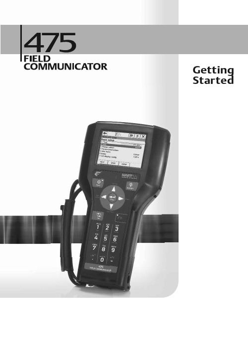
Started2Introduction3 Explosions could result in serious injury or death:Use in an explosive environment must be in accordance with the appropriate local, national, and international standards, codes, and practices. Please review the Reference Information and Product Certifications sections of the 475 Field Communicator User’s Manual for any restrictions associated with safe use. Electrical shock can result in serious injury or death.This device complies with Part 15 of the FCC Rules. Operation is subject to the following two conditions: (1) this device may not cause harmful interference, and (2) this device must accept any interference received, including interference that may cause undesired operation.©2009 Emerson Process Management. All rights reserved.HART is a registered trademark of the HART Communication Foundation.F OUNDATION is a trademark of the Fieldbus Foundation.IrDA is a registered trademark of the Infrared Data Association.Bluetooth is a registered trademark of the Bluetooth SIG, Inc.AMS Suite is a registered trademark of Emerson Electric Co.The Emerson logo is a trademark and service mark of Emerson Electric Co.All other marks are the property of their respective owners. INTRODUCTIONThe 475 Field Communicator Getting Started Guide provides basic guidelines, precautions, and setup information for the 475 Field Communicator. It does not provide in-depth instructions for configuration, diagnostics, maintenance, service, troubleshooting, or Intrinsically Safe (IS) installations. Refer to the 475 Field Communicator User’s Manual on the Resource CD or for more instructions.The 475 Field Communicator supports HART and F OUNDATION fieldbus devices, letting you configure or troubleshoot in the field. Electronic Device Description Language (EDDL) technology enables the 475 Field Communicator to communicate with a variety of devices independent of device manufacturer.4475 Field Communicator Overview 475 FIELD COMMUNICATOR OVERVIEWThe portable 475 Field Communicator includes a color LCD touch screen, a Lithium Ion battery (Power Module), a SH3 processor, memory components, and integral communication and measurement circuitry.When using the 475 Field Communicator to communicate with devices, follow all standards and procedures applicable to the location. Failure to comply may result in equipment damage and/or personal injury. Understand and comply with the sections in this manual.Working in a Hazardous AreaAn Intrinsically Safe (IS-approved) 475 Field Communicator can be used in Zone 0 (FM and CSA only), Zone 1, or Zone 2,for Group IIC, and Class I, Division 1 and Division 2, Groups A, B, C, and D locations.An IS-approved 475 Field Communicator may be connected to loops or segments that are attached to equipment located in Zone 0, Zone 1, Zone 2,for Group IIC; Zone 20, Zone 21, Zone 22,and Class I, Division 1 and Division 2,Groups A, B, C, and D locations.IS-approved 475 Field Communicators are ordered with the KL option and have an additional label on the back of the communicator that lists the approvals.CAUTIONYou can install or remove the Li-Ion battery in a hazardous area environment. You cannot charge the battery in this environment because the power supply/charger (00375-0003-0005) is not IS-approved.Using the Touch Screen and KeypadThe touch screen and keypad let you select menu items and enter text. Tap the screen with the provided stylus or use the up and down arrow keys on the keypad to select a menu item. See Figure1 for the location of the stylus. Double-tap the selected item on the screen or press the right arrow key on the keypad to open a menu item. CAUTIONContact the touch screen using blunt items only, preferably the stylus included with the 475 Field Communicator. Sharp instruments, such as screwdrivers, can damage the touch screen and void the warranty. Repairing the touch screen requires replacement of the entire display assembly, which is possible only at an authorized service center.475 Field Communicator Overview 5Figure 1. 475 Field Communicator HART and F OUNDATION fieldbus Communication Terminals (top)Stylus (in the strap)Bluetooth ® LightIrDA ® Interface (top) Touch Screen DisplayStrap attachment (top)Backlight Key Strap Attachment (side)Enter Key Function Key and Light (for multiple-key combination functionality)Li-Ion Battery (back) and System Card (internal)Strap Attachment (side)Strap Attachment (side)Lights Illuminated by Pressing the Charge Indicator Button (side)Alphanumeric Keypad Tab KeyNavigation Keys (four arrow keys)Strap Attachment (side)Power Key and LightCharge Indicator Button (side)Green Power Supply/Charger Connector on the Battery (side)6475 Field Communicator Overview Battery and Power Supply/ChargerUnderstand and follow the precautions below before using your battery or power supply/charger.•Protect the battery and power supply/charger from moisture, and respect operating and storage temperature limits. See the 475 Field Communicator User’s Manual for temperature limits.•Do not cover the battery or power supply/charger, subject it to prolonged periods of direct sunlight, or place it upon or next to heat-sensitive materials.•Charge the battery with only the power supply/charger. The power supply/charger should not be used with other products. Failure to comply may permanently damage your 475 Field Communicator and void the IS approval and the warranty.•Do not open or modify the battery or power supply/charger. There are nouser-serviceable components or safety elements inside. Opening or modifying them will void the warranty and could cause personal harm.•Follow all applicable regulations when transporting a Li-Ion battery.Charging the BatteryPrior to first portable use, fully charge the Li-Ion battery. The power supply/charger has a green connector to match the connector on the battery. The battery can be charged separately or while attached to the 475 Field Communicator. A full charge takes approximately two to three hours, and the 475 is fully operable when charging. An overcharge condition will not occur if power supply/charger remains connected after charging completes.To maintain performance, charge the battery frequently, preferably after each use. Limit full discharges, if possible. Additional information about maintaining the battery is in the 475 Field Communicator User’s Manual.Power Supply/Charger LightsThree colored lights are on the power supply/charger to indicate the conditions below. Each light displays a different color.Green The battery is fully charged.Flashing green The battery is nearly fully charged.Amber The battery is charging.Flashing amber The power supply/charger is not connected to the475 Field Communicator.Flashing amber and red The remaining charge in the battery is low.Red Charging cannot occur. Contact Technical Support formore information.Installing the System Card and Battery 7Figure 2. Back of the 475 Field CommunicatorINSTALLING THE SYSTEM CARD AND BATTERY1.Remove the protective rubber boot, if attached.2.Place the 475 Field Communicator face down on a level, secure surface.3.With the battery removed, slide the Secure Digital System Card (labeled SystemCard), with the card contacts facing up, into the System Card socket until it clicks. The System Card socket is spring-loaded. See Figure 2 for the System Card socket location. The System Card is not locked into the System Card socket in Figure 2. CAUTION The System Card must be supplied by the 475 Field Communicator manufacturer. Failure to comply will void the IS approval.4.With the 475 Field Communicator still face down, ensure the two battery retainingscrews are loose.5.Align the battery with the sides of 475 Field Communicator, and carefully slide the battery forward until it is secure.CAUTION The connector pins may be damaged if the battery and 475 Field Communicator are improperly aligned.6.Carefully hand tighten the two battery retaining screws. (Do not over tighten, 0.5Nmmaximum torque load.) The tops of the screws should be nearly flush with the 475 Field Communicator. Battery Retaining ScrewsLi-Ion BatteryConnector Pins System Card in the System Card Socket Main Unit LabelStrap AttachmentStrap AttachmentIS Label Location (KL Option)Stand8Removing the Battery and System Card REMOVING THE BATTERY AND SYSTEM CARD1.Remove the protective rubber boot, if attached.2.With the 475 Field Communicator off, place it face down on a level, secure surface.3.Loosen the two battery retaining screws until the top of each screw is above the topof the 475 Field Communicator.4.Slide the battery off the 475 Field Communicator.CAUTIONThe connector pins may be damaged if you pull the battery up rather than slide it off the 475 Field Communicator.5.Push the System Card into the System Card socket until it clicks and releases.6.Slide the System Card out of the System Card socket.STARTING THE 475 FIELD COMMUNICATORBefore startup, ensure the 475 Field Communicator is not damaged, the battery is fully seated, all screws are sufficiently tightened, and the communication terminals are free of dirt and debris.To start the 475 Field Communicator:1.Press and hold the Power key on the keypad until the green light on that key blinks(approximately two seconds). During startup, the 475 Field Communicator notifies you if an upgrade on the System Card needs to be installed. The FieldCommunicator Main Menu displays.e the touch screen or up and down arrow keys to select menu items. To open aselected menu item, double-tap it or use the right arrow key.3.To shut down, press the Power key and tap Shut down from the Power Switchscreen. Tap OK.COMMUNICATING WITH PC APPLICATIONSThe IrDA interface, Bluetooth interface (if licensed), and a supported card reader let the 475 Field Communicator or its System Card communicate with a PC. See Figure 1 for the location of the IrDA interface and the System Card. A card reader can only be used with the Easy Upgrade Utility. See the 475 Field Communicator User’s Manual for more information.Connecting to a Device9 CONNECTING TO A DEVICEUse the provided lead set to connect the 475 Field Communicator to the loop, segment, or device. Three communication terminals for the lead set are on the top of the 475 Field Communicator. Each red terminal is a positive connection for its protocol, and the black terminal is a common terminal shared by both protocols. An access door ensures that only one pair of terminals is exposed at any one time. Several markings indicate which pair of terminals is for which protocol.Only connections to a HART loop and F OUNDATION fieldbus segment are allowed. After the device is connected, double-tap HART Application or F OUNDATION Fieldbus Application from the Field Communicator Main Menu. The appropriate device description is also required. Refer to the latest version of the 475 Field Communicator User’s Manual for details.CAUTIONThe 475 Field Communicator draws approximately 12 mA from the fieldbus segment. Ensure the power supply or barrier on the fieldbus segment has the capacity to provide this additional current. If a fieldbus segment is drawing near the capacity of the segment’s power supply, connecting the 475 Field Communicator may result in loss of communication.TECHNICAL SUPPORTContact your supplier or go to for Technical Support contact information.MAINTENANCE AND REPAIRAny maintenance, repair, or replacement of components not listed below must be performed by specially trained personnel at an authorized service center. You can perform common maintenance procedures listed below:•Cleaning the exterior. Use only a dry, lint-free towel or dampen the towel with a mild soap and water solution.•Charging, removing, and replacing the battery.•Removing and replacing the System Card.•Removing and replacing the stand.•Ensuring that all exterior screws are sufficiently tightened.•Ensuring that the communication terminal recess is free of dirt and debris.10Waste Disposal WASTE DISPOSALProducts with the following label comply with the Waste Electrical and Electronic Equipment (WEEE) directive, 2002/96/EC, which applies to European Union (EU) member states only.The label indicates this product should be recycled and not treated as Array household waste. Customers in EU member states should contact theirEmerson sales representative for information on discarding any part of the475 Field Communicator.For customers in all other world areas, if it is necessary to discard any part of the 475 Field Communicator, follow the waste-disposal regulations applicable in your location. HAZARDOUS SUBSTANCESProducts with the following label are lead-free and comply with the Restriction of the Use of Certain Hazardous Substances in Electrical and Electronic Equipment (RoHS) directive, 2002/95/EC, which applies to EU member states only.The purpose of the directive is to limit the use of lead, cadmium, mercury, Array hexavalent chromium, polybrominated biphenyl (PBB), and polybrominateddiphenyl ether (PBDE) flame retardants in electronic equipment. PRODUCT CERTIFICATIONSOverviewAll 475 Field Communicators have the main unit label (see Figure2). Intrinsically Safe (KL option) 475 Field Communicators also have a label opposite the main unit label. If the 475 Field Communicator does not contain this label (NA option), it is not Intrinsically Safe. See the 475 Field Communicator User’s Manual or for additional approval information.The Industry Canada (IC), Federal Communications Commission (FCC), and Radio and Telecommunications Terminal Equipment (R&TTE) approvals apply to only 475 Field Communicators licensed for Bluetooth.Approved Manufacturing LocationsEmerson Process Management — Leicester, EnglandICThis Class A digital apparatus complies with Canadian ICES-003.Product Certifications11 FCCThis equipment has been tested and found to comply with the limits for a Class A digital device, pursuant to part 15 of the FCC Rules. These limits are designed to provide reasonable protection against harmful interference when the equipment is operated in a commercial environment. This equipment generates, uses, and can radiate radio frequency energy and, if not installed and used in accordance with the instruction manual, may cause harmful interference to radio communications. Operation of this equipment in a residential area is likely to cause harmful interference in which case the user will be required to correct the interference at his own expense. Any modifications made to this device that are not approved by Emerson Process Management may void the authority granted to the user by the FCC to operate this equipment.European Directive Information — CE Compliance Electromagnetic Compatibility (2004/108/EC)Tested to the EN 61326-1 specification.R&TTEThis equipment is in conformity with the Radio and TelecommunicationsTerminal Equipment (R&TTE) Directive 1999/5/EC.ATEX Directive (94/9/EC) (KL option only)Emerson Process Management complies with the ATEX Directive. Applicable standards are EN 60079-0, EN 60079-11, EN 60079-26, and EN 60079-27.Specific ATEX Directive Information is located within this document and the475 Field Communicator User’s Manual.Hazardous Locations Certifications (KL option only)The Intrinsic Safety approvals listed in this section include compliance with the FISCO requirements.North American CertificationsFactory Mutual (FM)Intrinsically Safe for Class I, Division 1, Groups A, B, C, and D and Class I,Zone 0, AEx ia IIC T4 (Ta = 50°C) hazardous locations when connected asindicated in the control drawing 00475-1130 in the 475 Field CommunicatorUser’s Manual. See the control drawing for input and output parameters.Canadian Standards Association (CSA)Intrinsically Safe for use in Class I, Zone 0, Ex ia IIC T4 (Ta = 50°C) hazardous locations when connected as indicated in the control drawing 00475-1130 inthe 475 Field Communicator User’s Manual. See the control drawing for input and output parameters.Product Certifications 12International CertificationIECExCertification No.: BVS 09.0012Ex ia IIC T4 (-10°C ≤ Ta ≤ 50°C)European CertificationsATEX Intrinsic Safety≤ Ta ≤ +50°C)HART Intrinsically Safe Electrical ParametersF OUNDATION fieldbusThe FISCO standard applies to the FM, CSA, IECEx, and ATEX certifications.U i = 30 Volt DCI i = 200 mA P i = 1.0 WattL i = 0C i = 0U 0= 1.9 Volt DCI 0= 32 μAU iIIC = 17.5 Volt DC I iIIC = 215 mA P iIIC = 1.9 WattU iIIB = 17.5 Volt DC I iIIB = 380 mA P iIIB = 5.3 Watt U 0= 1.9 Volt DC I 0= 32 µAU i = 30 Volt DC I i = 380 mA P i = 1.3 WattU 0= 1.9 Volt DC I 0= 32 µA L i = 0C i = 0。
HART475手操器教程
HART475手操器教程一、HART475手操器的基本功能:1.HART通信协议支持:HART475手操器支持HART通信协议,能够与HART通信设备进行双向通信,并获取到设备的各种参数和状态信息。
2.设备参数配置:通过HART475手操器,可以对HART通信设备的各项参数进行配置,例如设备的通信地址、测量范围、报警阈值等。
3.设备操作控制:HART475手操器可以通过发送指令,对HART通信设备进行操作控制,例如设备的启动、停止、复位等。
4.设备监控与诊断:HART475手操器能够实时显示HART通信设备的工作状态和参数数值,便于用户对设备进行监控和故障诊断。
二、HART475手操器的使用方法:1.连接通信设备:首先,需要将HART475手操器与HART通信设备进行连接。
通常情况下,使用连接线将手操器的通信口与设备的HART通信接口连接,并确保连接稳固。
2.打开HART475手操器:按下手操器的电源键,屏幕上将显示出设备的开机画面,然后进入主界面。
3.选择通信方式:在主界面中,通过手操器上的导航键和确认键,选择HART通信协议,并进入通信方式选择界面。
4.选择设备:从通信设备列表中,选择要进行配置和操作的HART通信设备,并确认选择。
5.配置设备参数:进入设备参数配置界面后,可以通过手操器上的导航键和数字键,输入和调整设备的各项参数。
完成参数配置后,按下确认键保存设置。
6.操作设备:通过手操器上的菜单键和指令键,选择要对设备进行的操作,并按下确认键执行操作。
例如,启动设备、停止设备或复位设备等。
7.监控设备:在设备监控界面中,手操器将实时显示设备的各种参数数值和状态信息。
通过导航键和刷新键,可以查看各项参数的变化趋势和工作状态。
8.诊断设备故障:在设备监控界面中,手操器还提供了故障诊断功能。
通过选择诊断菜单,手操器将对设备进行自动诊断,并显示出故障原因和解决方案。
9.退出手操器:当完成对设备的配置、操作和监控后,按下手操器的退出键,手操器将进入关机状态。
罗斯蒙特475HART手操器中文说明
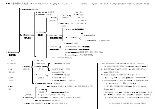
HART手操器中文说明HART手操器开机后显示:1、offline (离线),2、online(上线),3,frequency device (设备频率),4、utility(效用)。
我们一般选2,online(上线)后进入左边菜单,本说明介绍了几乎其所有子菜单功能。
Process variables(变量作用)、TEST DEVICE(设备测试)1、LRV(零点)、LOOP TEST(回路测试)1、2、URV(满度)1、(键区输入) 3、UNIT(单位)(重调范围4、LSL(量程低限)APPLY 5、USL(量程上限)(应用值)1、D/A trim (输出电流调整)、(校准)Analog output 1、proceed (继续)(使用服务) (2、2、scaled D/A trim (“点”输出电流调整)1、Zero trim (零点测试)、sensor trim2、Lower sensor trim (零点调整)(传感器调整3、Upper sensor trim (满度调整)1、Device setup4、Snsr trim cal typ (传感器类型:差压、绝压、压力)(设备设置)5、sensor trim poin (“点”传感器调整)4、Recall fact trim(传感器真实记录)2、PV 、TAG(标签)(压力测量值)、UNIT(单位)1、keypad input (键区输入) (备注:比如我们校验一个量程为0-350kpa的差压变送器,其步骤如下:3、、RANGE V(1)连接好变送器校验所需仪器。
(如:DRUCK,250Ω电阻,HART等)3、AO (基础设置) (范围值)2、APPLY UALES (应用值)(2)、HART选择online 看LRV(零点)是否为0 kpa,URV(满度)是否为(输出电流)1、Date (修改日期) 350 kpa若不是进行修改。
、2、DESCRIPTOR (解说符)(3)、校验零点:变送器正负压侧都对大气,HART选择online后4、LRV (设备信息) 3、MESSAGE (通讯)1、Device setup2、Diag/service(零点)4、WRITE PROTECT (写入保护)3、Calibration 3、sensor trim 2、Lower sensor trim5、XFER FNCTN LINEAR (线性转移)(输入0 kpa OK 即可)即:1-2-3-3-25、URV 、Pessur(1、压力温度,2、传感器设定,3、传感器真实记录4、单位)(4)满度校验:从变送器正压侧打压到350 kpa 稳定,同上1-2-3-3-3(满度)1、Sensor 输入350 kpa即可(传感器、Temperature sensor (温度) (5)输出电流调整:零点,HART 1-2-3-2-1 到D/A trim 后读取Druc上的电流(详细设置) 2、signal condiation (信号情况:单位、阻尼) 值输入HART上4mA校验点。
知识|哈特(HART)475手操器使用教程
知识|哈特(HART)475手操器使用教程HART手操器:HART(Highway Addressable Remote Transducer),可寻址远程传感器高速通道的开放通信协议,是一种用于现场智能仪表和控制室设备之间的通信协议。
使用它几乎可用来完成所有的现场仪表检修调试工作,包括故障诊断,日常检修,开车调试,校准等。
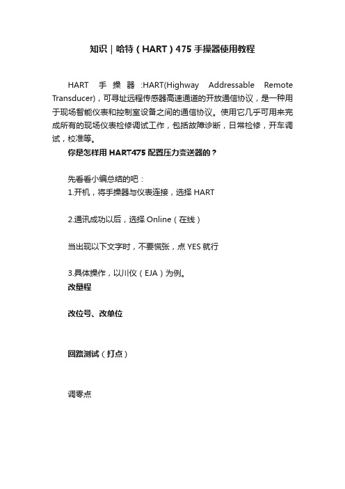
你是怎样用HART475配置压力变送器的?先看看小编总结的吧:1.开机,将手操器与仪表连接,选择HART2.通讯成功以后,选择Online(在线)当出现以下文字时,不要慌张,点YES就行3.具体操作,以川仪(EJA)为例。
改量程改位号、改单位回路测试(打点)调零点PS:在更改完数据后要选“SEND”发送给变送器HART475图形图像都说明了啥现场通讯器屏幕布局常用按钮使用下列按钮,可修改窗口上曲线图和图表的(以艾默生HART475为例)平移,触击按钮,选择图表或曲线图中的一点,拖动此点在窗口中反复地移动。
区域缩放,触击按钮,然后触击并拖动图表中的一点来创建放大的方框。
当您从窗口释放触笔后,图表将放大并适应此区域。
此控件仅可用于条形图表和曲线图。
放大,触击此按钮,从图表中心以固定比率放大。
再次触击,重复此操作。
缩小,触击此按钮,从图表中心以固定比率缩小。
再次触击,重复此操作。
重置,触击按钮,将图表或曲线图返回至原始主屏幕,取消您执行的任何平移或缩放操作。
下拉列表,触击此菜单,在不同的变量中选择,在图表上或曲线图的不同波形中高亮显示。
图形选项图像图像是设备的全屏幕照片。
图像可包含标识和多种图形,如容器。
要查看图像,选择菜单中的图像或绘图标签。
显示全屏幕图像。
要返回菜单视图,按任何键或触击触摸屏。
一些图像具有链接,可以运行方法或查看附加菜单。
如果图像具有链接,将在菜单中的图像或绘图标记旁出现箭头。
当打开图像后,使用向左键返回菜单、或按任意键启动方法或与图像或图纸关联的附加菜单。
如果链接未与图像关联,按任意键返回菜单。
HART475手持器说明书
- 1 -HART475手持通讯器使用说明书一使用指南1.1简介HART475 HART®手持器是支持HART®协议设备的手持通信器,它可以对所有符合HART®协议的设备进行配置、管理和维护。
见图1。
图1. HART475 HART®手持器HART475手持器可以方便的接入4~20mA HART®协议仪表电流回路中,与HART®协议仪表进行通信,配置HART®仪表的设定参数(如量程上下限等),读取仪表的检测值、设定值,可以对仪表进行诊断和维护等等。
该手持器支持HART®协议的第一主设备(HART®网桥等),也支持HART®协议的点对点和多点通信方式。
1.2手持器连接HART475手持器可以在远端控制室或仪表就地接入单独对HART®仪表进行通信操作。
连接如图3所示,手持器可以并联在HART®协议设备上,也可以并联在其负载电阻(250Ω)上。
连接时不必考虑引线的极性。
图2. 后连接面板图3. 手持器连接图注意:为保证手持器通信正常,在回路中必须有最小值为250Ω的负载电阻。
手持器不直接测量回路电流。
1.3打开手持器首先检查手持器已经装好了电池,检查如图3中的仪表回路供电正常后,按下手持器的键一秒钟以上打开手持器(在起动后再按该键一秒钟以上可关闭手持器),手持器启动后将自动在4~20mA回路上寻找轮询地址为零的HART®设备。
1.4常用功能指导1.4.1监视变量(读取检测值)在线状态时,选择第一项Process Variables并按右箭头键,即可进入监视变量功能。
如在离线状态,按以下操作即可进入监视变量功能:“1 Online”(在线)→“1 Process variables”(监视变量)1.4.2设定主变量单位在线状态时,按以下操作即可进入设定主变量单位功能:“4 Detailed setup”(详细设置)→“2 Signal condition”(信号条件)→“1 PV Unit”(主变量单位)1.4.3设定量程上限在线状态时,按以下操作即可进入设定量程上限功能:“4 Detailed setup”(详细设置)→“2 Signal condition”(信号条件)→“2 PV URV”(量程上限)1.4.4设定量程下限在线状态时,按以下操作即可进入设定量程下限功能:“4 Detailed setup”(详细设置)→“2 Signal condition”(信号条件)→“3 PV LRV”(量程下限)- 3 -1.4.5设定阻尼在线状态时,按以下操作即可进入设定阻尼功能:“4 Detailed setup”(详细设置)→“2 Signal condition”(信号条件)→“4 PV Damp”(阻尼)1.4.6输出电流校准在线状态时,按以下操作即可进入输出电流校准功能:“2 Diag/Service”(诊断及服务)→“3 Calibration”(校准)→“2 D/A trim”(输出电流校准)注意:输出校准电流功能一般在HART®仪表出厂和仪表周期检定时才可进行。
hart475手操器培训手册[1]
![hart475手操器培训手册[1]](https://img.taocdn.com/s3/m/6384ed0976c66137ee061978.png)
HART手操器培训内容手操器培训内容二○○九年五月HART® 手操器概述HART 通讯协议简介HART(Highway Addressable Remote Transducer),是可寻址远程传感器高速通道的开放通信协议,是美国Rosement 公司于1985年推出的一种用于现场智能仪表和控制室设备之间的通信协议。
HART 协议的主要优点是能兼容数字信号通讯和模拟信号传输。
HART 手操器的使用(一) 如何连接(只要连接到变送器接线端子上,或者这个回路的任意连接点都可进行通讯) (二) 按键、功能键功能表1-1 功能键标签(三) 主菜单(MAIN MENU )1、 Offline 脱机菜单(是用户用来自定义设备设置数据的,或者查看已保存过的设备数据,包括一些制造商、设备型号、版本等) 2、 Online 联机菜单3、 Frequency Device 设备频率菜单(主要显示变送器的输出频率值及相对应的输出压力值)4、 Utility 公共程序菜单(主要是手操器设置菜单包括设置轮询、调整LCD 对比度、设置手操器的自动关闭时间等,这里第5项为仿真菜单,允许在不连接设备时仿真一台HART兼容设备的联机状态,是一个训练工具。
):主要介绍Online 联机菜单联机菜单:连上HART兼容设备,在主菜单在按 进入联机菜单如图。
联机菜单在联机菜单的首行显示设备的名称及仪表位号。
当特定设备的设备描述不在手操器中时,HART手操器会提供一个通用操作界面。
通用界面允许你向HART兼容设备执行通用的功能。
Generic Online(通用联机)菜单树。
通用联机菜单首先出现在通用界面。
该菜单显示一些必须的近前的设备信息,例如:测量值(PV)、模拟输出值(AO)、量程下限(LRV)和量程上限(URV)等。
需通过设备设置Device setup选项访问连接设备的设置参数。
以下功能可以在通用联机菜单中使用:SAVE(保存)功能键允许你保存变送器的设置。
475_PDS HART 手操器说明书

475Field CommunicatorProduct Data SheetJuly 2009I Full-color graphical user interfaceI Powerful field diagnostics I Bluetooth ®communication I Long-lasting Lithium-Ion power moduleIUniversal support for HART ®and F OUNDATION TM fieldbusdevices475Field CommunicatorWhat you get is the most powerful handheld available –universal,user upgradeable,intrinsically safe,rugged and reliable.Only the 475Field Communicator can deliver all this in a single handheld communicator.IntroductionThe 475Field Communicator builds on the industry-leading technology of the 375Field Communicator while adding innovative newcapabilities including color display,Bluetooth communication,and advanced field diagnostics.The 475Field Communicator is designed to support all HART and F OUNDATION fieldbus devices from all vendors.Product Data Sheet July2009Product DescriptionThe475Field Communicator is designed to simplify your work in the field.The intuitive full color user interface allows you to leverage the same practices for both HART and F OUNDATION fieldbus devices.It includes a larger touch screen than PDAsor Pocket PCs,supports HART versions5,6,and7(including WirelessHART™)devices,and allows you to upgrade your475 Field Communicator onsite using the Internet.See and Feel the Difference The touch screen display uses transflective technology,making it easy to read in both bright sunlight and normal lighting.To make sureall conditions are covered,amulti-level backlight is included,allowing bright,crisp display evenin plant areas with dim light.The touch screen display and largephysical navigation buttons providefor efficient use both on the benchand in the field.The full color graphics capability isprovided as standard with every475Field Communicator.It usespowerful EDDL technology to allowyou to read data from field devicesin a graphical manner.Charts,graphs,gauges,and productimages are just a few of the waysin which important device data canbe displayed using the475FieldCommunicator’s color LCD display.The weight of the475FieldCommunicator is evenlydistributed for comfortableone-handed operation in the field.It runs on Windows CE,a robust,real-time operating system.The475Field Communicatorhas plenty of memory to allow forfuture expansion.It has32MB ofapplication memory and1GB ofmemory on its System Card.User UpgradeableEasy Upgrade Keeps YourCommunicator CurrentThe475Field Communicator isuser upgradeable via the Internet.Avoid the time delays of sendingyour communicator to a servicecenter for upgrades.With theEasy Upgrade option,you candownload new device drivers,functionality,or licenses directlyto your475Field Communicator.Keeping your475FieldCommunicator updated is easy.New HART and F OUNDATIONfieldbus devices,as well asfunctional updates to existingdevices,are introduced continuallyby device vendors.Keepingup-to-date with the requiredDevice Descriptions(DDs)for allthe devices in your plant can bea real challenge.With Easy Upgrade,when newHART and F OUNDATION fieldbusDDs become available,you cansimply download them from theInternet and upgrade your475Field Communicator.Update atyour site,within your control,when it’s convenient for you.Designed not only for use on the bench,the475Field Communicator also enables you to do those tasks that just have to be done in the field.Page2Through Easy Upgrade ,you always have access to the latest HART and fieldbus drivers.With the 475Field Communicator,you are guaranteed universal HART and F OUNDATION fieldbus support in a single,intrinsically safe handheld communicator.Page 3Online LicensingThe Online Licensing capability provided with Easy Upgradeallows you to enable new options for your 475Field Communicator over the Internet.With Online Licensing,powerful options like F OUNDATION fieldbus can be added by simply purchasing the license and downloading it directly to your communicator.Universal –HART and F OUNDATION fieldbusWith over 1,100different HART and F OUNDATION fieldbus devices available from more than 100manufacturers,the 475Field Communicator works with all your devices to positively impact your bottom line.475FieldCommunicatorThe Easy Upgrade Utility allows you to transfer system software,DDs,and HART device configurations between the 475Field Communicator and a PC.Connect using IrDA,Bluetooth,or an SD Card Reader.((()))Easily store and print device configurations for analysis and documentation requirements.Rugged and ReliableIt’s called “Field Communicator”for a reason.Some tasks just have to be performed at thedevice in the field.The 475Field Communicator is designed for tough use in your plant or mill.Its large keys and physical navigation buttons allow forone-handed operation,even with your work gloves on.The rugged display is designed to take the knocks and shocks from normal use in the plant.The 475Field Communicator’s Protective Rubber Boot provides added protection in the field and in your toolbox.Both the rubber boot and 475housing are designed in accordance with Intrinsic Safety standards to limitIntrinsically SafeThe 475Field Communicator meets the Intrinsic Safety requirements of the listed regulatory agencies andstandards.All of the available Hazardous Locations approvals are provided in a single model option (see Ordering Information).–CENELEC/ATEX –Factory Mutual (FM)–Canadian Standards Association (CSA)–FISCO –IECExPage 4Product Data SheetJuly 2009the build up of static electrical energy.The 475Field Communicator is designed,manufactured,and tested to very demandingspecifications.It is ready to go wherever you need to go to get the jobdone.ATEXThe 475Field Communicator,with its handy carrying case,provides a single tool for configuring and diagnosing HART and F OUNDATION fieldbus devices.Even the power module is approved for installation in hazardousareas.The protective rubber boot provides added protection in the field.Page 5475FieldCommunicatorPowerful DiagnosticsInterface with AMS Device ManagerThe 475Field Communicator is fully compatible with AMS Device Manager,the industry standard for asset management software.In fact,Control Magazine readers have selected AMS Device Manager as the #1Calibration Software package for over 10years in a row.AMS Device Manager uses the intelligence from field devices to create a predictive maintenance environment.AMS Device Manager allows you to configure,calibrate,configurations in yourcommunicator or transfer them to AMS Device Manager.Together,the 475FieldCommunicator and AMS Device Manager enable you to efficiently manage all of your devices.Device Configuration ManagementUsing the Easy Upgrade Utility,you can back up hundreds of device configurations and can transfer them between your communicator and a PC.This library of device configurations is easy to view and print for analysis.document,and troubleshoot HART ,F OUNDATION fieldbus,and WirelessHART devices.Transfer device configuration data to AMS Device Manager via the IrDA port or Bluetooth interface on your 475Field Communicator and PC.Take your 475Field Communicator out to the field to configure or update one or more devices.Save up to 1,000devicePage 6Product Data SheetJuly 2009Detect power supply problems by monitoring low frequency noise on a segment.Locate incorrect terminations and faulty devices by diagnosing the communications signal level.For HART loops,the 475Field Communicator allows you to verify whether the DC voltage in the loop is correct.Diagnose Network Problems The 475Field Communicator can be used to configure all the F OUNDATION fieldbus devices in your e it to perform diagnostics for effective start-up and troubleshooting of fieldbus segments.Create a quality segment by diagnosing the network DC voltage and average noise.SpecificationsMicroprocessorI 80MHz Hitachi ®SH3Memory Internal Flash I 32MBSystem CardI 1GB secure digital card RAMI 32MB WeightI Approximately 1.65lb.(0.75kg)with battery DisplayI 1/4VGA (240by 320pixels)color,3.5in.(8.9cm)transflective display with touch screen I Anti-glare coatedKeypadI 25keys including 4action keys,12alphanumeric keys,tab key,function key,backlight key,power key,and 4cursor-control (arrow)keys;membrane design with tactile feedbackUsageI -10°C (14°F )to +50°C (122°F )I 0%to 95%RH (non-condensing)for 0°C (32°F )to +50°C (122°F )ChargeI 10°C (32°F )to +40°C (104°F )Storage With BatteriesI -20°C (-4°F )to +55°C (131°F )Storage Without BatteriesI -20°C (-4°F )to +60°C (140°F )Enclosure Rating I IP51(from front)ShockITested to survive a 1-meter drop test onto concrete UsageIPC with Internet access I CD Rom driveI IrDA port (or adapter)or Bluetooth (or adapter)I SD Card Reader (required for some upgrades)I Windows XP (SP2or SP3)or Windows Vista Business (SP1)BatteryI Rechargeable Lithium-Ion power module Battery Operating TimeI 20hours –continuous use I 40hours –typical use I 80hours –standby modeBattery Charger OptionsI Input voltage 100-240VAC,50-60Hz I Cables included with U.S.,Europe,and U.K.plugs Battery ChargerIMini DIN 6-pin jackHART and FieldbusI Three 4mm banana plugs (one common to HART and F OUNDATION fieldbus)IrDA PortI IrDA (Infrared Data Access)port supporting up to 115KbpsI ±15degrees recommended maximum angle from center lineI Approximately 18in.(45.7cm)recommended maximum distance BluetoothI Up to 32.8ft.(10m)communication distanceI Uses standard Windows drivers I FCC,IC,and CE approvals475Field Communicator Spare Parts ListRuggedized 250Ohm Load Resistor 00275-0096-0001Rechargeable Lithium-Ion Power Module00475-0002-0022Power Supply &Charger (Li-ion/NiMH)US/UK/EU connection types included 00475-0003-0022Power Supply/Charger Standard Cord Set (US/UK/EU cords)00475-0003-0002Power Supply/Charger Australia (AU)cord 00475-0003-0003Leadset with connectors 00375-0004-0001Mounting Straps00475-0005-0002Carrying Case (with straps)00475-0005-0003Magnetic Hangar 00475-0005-0004Protective Rubber Boot 00475-0005-0005Stylus (pack of 2)00475-0006-0001IrDA to USB Adapter (1)00375-0015-0002System Card (SD)Reader (with USB Interface)(2)00375-0018-0022Bluetooth Adapter (1)00475-0018-0023Stand00475-0044-0001Getting Started Guide 00475-0045-3001F OUNDATION fieldbus License Via Web 00375-0142-0002Easy Upgrade (New)License via Web(3)00375-0142-0003(3)(5)AMS Device Manager Field Communicator Interface Kit (25tags)AW7005HC00025AMS Device Manager Field Communicator Interface Kit (100Tags and above)AW7005HC20000(1)Can be used to support communication between the 475and the Easy Upgrade Programming Utility or AMS Device Manager (with Handheld Communicator Interface Kit.IrDA or Bluetooth communication is required to register the 475and use the Online Licensing system.(2)The System Card (SD)Reader allows a user to upgrade a System Card much faster than when using IrDA or Bluetooth.Due to file size constraints,major upgrades require the use of a card reader.(3)The Easy Upgrade feature allows users to add new System Application software and Device Descriptions (DDs)to the 475for a period of 3years.To upgrade without this feature,the System Card must be sent to a Service Center and the upgrade will be completed for a fee.(4)The Field Communicator Online Licensing system is available to end users but it may also be performed by an agent on the user's behalf.It is at the agent's discretion if an additional fee should apply.Any order must be accompanied by the System Card S/N.Instant notification available licenses for download can be provided to email addresses provided at time of order.For more details,see the Online Licensing procedure at (5)The ReNew option is available on System Cards where the Easy Upgrade license has been expired for less than 90days.Date of expiration can be obtained by inter facing the 475with v1.6.0(or higher)of the Easy Upgrade Programming Utility.(6)Requires AMS Device Manager (v6.2or higher).Both AMS Device Manager and the Handheld Communicator Interface Kit are available for sale through select channels only.See for more details.Page 7475Field Communicator©2009,Emerson Process Management.The contents of this publication are presented for informational purposes only,and while every effort has been made to ensure their accuracy,they are not to be construed as warranties or guarantees,express or implied,regarding the products or services described herein or their use or applicability.All sales are governed by our terms and conditions,which are available on request.We reserve the right to modify or improve the designs or specifications of our products at any time without notice.All rights reserved.AMS is a mark of one of the Emerson Process Management group of companies.The Emerson logo is a trademark and service mark of Emerson Electric Co.All other marks are the property of their respective owners.Emerson Process Management Asset Optimization Division 12001Technology DriveEden Prairie,MN 55344USA T 1(952)828-3206F 1(952)828-3006Product Data SheetMay 2009475Field Communicator475Field Communicator Ordering Information475Field Communicator (1)P Rechargeable Lithium-Ion Power Module Code Power Supply/Charger1Power Supply and Charger NiMH/Li-Ion (US/UK/EU connection types included)(3)9Not included (4)Code Language E English D German J Japanese R RussianCode Product CertificationsKL ATEX,FM,CSA and IECEx Intrinsically Safe (includes FISCO as applicable)NA No Approval Code Easy UpgradeU Easy Upgrade (3year)Option (5)9Not IncludedCode Standard OptionsGMGraphics (included at No Charge)(6)Device Configuration Management (included at No Charge)(7)Code Bluetooth T Bluetooth Communication (8)9No Bluetooth Communication Code Options A Spare Rechargeable Lithium-Ion Power Module (9)S Protective Rubber Boot with Stand Typical HART Model Number:475H P 1E KL U GMT Typical HART/Fieldbus Model Number:475F P 1E KL U GMT(1)Base Model 475includes Field Communicator unit with Color LCD display,System Card,leadset with connectors,carrying case,Getting Started Guide,Resource CD,stylus,and straps.(2)Must specify Easy Upgrade Option (Code U)when ordering this model option.(3)To obtain an Australia power cord,order part number 00375-0003-0003.(4)This option should only be considered if the user already has a 375or 475Power Supply/Charger.If it is a 375Power Supply /Charger,it must be the Li-Ion/NiMH version.(5)The Easy Upgrade capability allows users to add new System Application software and Device Descriptions (DDs)to the 475for a period of 3years.To upgrade without this feature,the System Card would have to be sent to a Service Center.(6)The Graphics functionality enables a user to access enhanced grapical features when using the HART or F OUNDATION fieldbus application.(7)Device Configuration Management provides the capablity to store in excess of 1,000configurations and print them.(8)Bluetooth enables communication to a PC via the Bluetooth protocol.(9)A fully charged Lithium-Ion Power Module is capable of delivering power for 20hours of typical field use.If requirements exceed this specification,a Spare Power Module (code A)should be specified.。
Hart475手操器使用手册
• 若出现通讯不上,首先检查 HART 回路中现场设备的电流和电压。几乎所有的现场设 备都至少需要 4mA 和 12VDC 以维持正常运行。
• 检查回路中的阻抗,看回路中是否接入了 250 欧姆的外部阻抗。接入 250 欧姆电阻, 将引线接入 250 欧姆电阻的两端。再查看通讯是否正常。
ቤተ መጻሕፍቲ ባይዱ第一部分
使用说明
HART 手操器:HART(Highway Addressable Remote Transducer),可寻址远程传感器
高速通道的开放通信协议,是一种用于现场智能仪表和控制室设备之间的通信协议。
使 用 它 几 乎 可 用 来 完 成 所 有 的 现 场 仪 表 检 修 调 试 工 作 ,包 括 故 障 诊 断 ,日 常 检 修 ,开
IM-AGE 操作,2.0 及以上版本的 475 手操器才有 RE-IMAGE 操作功能。步骤:进入 475 手操器 Main menu→Settings→About HART475;选择 RE-FLASH 或 RE-IMAGE→YES。 按 OK 开始后要耐心等待,RE-FLASH 耗时约 20min,RE-IMAGE 耗时约,50min。操作完 成 后 ,屏 幕 会 有 提 示 ,根 据 提 示 操 作 即 可 。操 作 时 一 定 要 把 充 电 器 插 上 ,因 为 本 操 作 很 耗 电 。操 作 过 程 中 ,禁 用 待 机 和 自 动 关 机 计 时 器 ,否 则 可 能 会 导 致 无 法 修 复 的 严 重 后果。 点触笔无法对 475 手操器进行操作时,可对触屏进行校准。步骤进入 HART475 手操器 Main menu→Settings,Delete 键进入下一级菜单→Touch Screen Alignment,按 Delete 键进入校准界面,在屏幕中央会出现一个十字符号,用点触笔点中十字符号, 十字符号会依次出现在 5 个位置上,用点触笔依次点中十字符号后,触屏即可恢复正 常。 4、通信地址不对 检查压力变送器是否被设置为非零地址,处于轮询多点回路模式,可将 475 手操器轮 询 模 式 设 置 为 使 用 地 址 轮 询 ,设 置 为“ 0 ”则 为 轮 询 非 多 点 回 路 。轮 询 地 址 或 位 号 与 压 力变送器不匹配,使用了不正确的轮询地址也会无法通信。检查压力变送器与 475 手 操器的通信是否被控制系统所禁止,可通过停止控制系统的 HART 通信,475 手操器与 压力变送器之间的通信就能恢复正常。
HART475说明书
目录第一章基本使用 (1)1.1 电池组(操作前请先关机) (1)1.2 开机注意事项 (2)1.3 键盘使用 (2)第二章在线操作菜单 (4)2.1 检测菜单 (4)2.1.1 轮询检测 (4)2.1.2 按轮询号检测 (4)2.1.3 选择设备类型 (4)2.2 压力变送器主菜单 (5)2.2.1 过程变量 (5)2.2.2 组态与测试 (5)2.2.3 特征化 (7)2.2.4 校准 (11)2.3 涡街流量计主菜单 (12)2.4 靶式流量计主菜单 (12)2.5 V锥流量计主菜单 (12)2.6 通用主菜单 (13)2.6.1 过程变量 (13)2.6.2 诊断与维护 (13)2.6.3 基本设置 (15)2.6.4 详细设置 (17)2.6.5 浏览 (18)第三章提示界面 (19)3.1 电池欠压警告 (19)3.2 通信故障警告 (20)3.3 日期输入错误 (20)3.4 数据输入错误 (20)Hart菜单树及操作步骤 (21).'第一章基本使用本通讯器适合HART协议智能压力变送器、v锥流量计、靶式流量计以及涡街流量计的通讯操作,与HART275.HART375兼容,具有极好的兼容性,可通讯115 1,3051,EJA,ABB及其他HART协议的进口仪表,完全兼容国产的各种智能压力变送器1.1装电池组(操作前请先关机)1、将现场通讯器正面向下放在平稳的地方,注意不要毁坏液晶屏。
(如图1-1)2、推开电池盖锁,打开开后盖更换电池。
图1-1.'1.2开机注意事项在开机前,请确保以下几点:①该现场通讯器没有物理机械损坏②电池组已经装好③将现场通讯器连接到回路(如图1-2)图1-2启动手操器按住“开关”键,直到液晶屏亮,开机成功。
关闭手操器按住“开关”键,直到液晶屏关闭,关机完成。
1.3键盘使用开关键该键用于启动或关闭现场通讯器。
导航箭头键四个导航箭头键提供菜单选择功能。
HART475说明书

目录第一章基本使用 (1)1.1 电池组(操作前请先关机) (1)1.2 开机注意事项 (2)1.3 键盘使用 (2)第二章在线操作菜单 (4)2.1 检测菜单 (4)2.1.1 轮询检测 (4)2.1.2 按轮询号检测 (4)2.1.3 选择设备类型 (4)2.2 压力变送器主菜单 (5)2.2.1 过程变量 (5)2.2.2 组态与测试 (5)2.2.3 特征化 (7)2.2.4 校准 (11)2.3 涡街流量计主菜单 (12)2.4 靶式流量计主菜单 (12)2.5 V锥流量计主菜单 (12)2.6 通用主菜单 (13)2.6.1 过程变量 (13)2.6.2 诊断与维护 (13)2.6.3 基本设置 (15)2.6.4 详细设置 (17)2.6.5 浏览 (18)第三章提示界面 (19)3.1 电池欠压警告 (19)3.2 通信故障警告 (20)3.3 日期输入错误 (20)3.4 数据输入错误 (20)Hart菜单树及操作步骤 (21)第一章基本使用本通讯器适合HART协议智能压力变送器、v锥流量计、靶式流量计以及涡街流量计的通讯操作,与HART275.HART375兼容,具有极好的兼容性,可通讯115 1,3051,EJA,ABB及其他HART协议的进口仪表,完全兼容国产的各种智能压力变送器1.1装电池组(操作前请先关机)1、将现场通讯器正面向下放在平稳的地方,注意不要毁坏液晶屏。
(如图1-1)2、推开电池盖锁,打开开后盖更换电池。
图1-11.2开机注意事项在开机前,请确保以下几点:①该现场通讯器没有物理机械损坏②电池组已经装好③将现场通讯器连接到回路(如图1-2)图1-2启动手操器按住“开关”键,直到液晶屏亮,开机成功。
关闭手操器按住“开关”键,直到液晶屏关闭,关机完成。
1.3键盘使用开关键该键用于启动或关闭现场通讯器。
导航箭头键四个导航箭头键提供菜单选择功能。
按→进下一级菜单,按←键返回上级菜单,按↓↑键可以在菜单中切换。
艾默生-罗斯蒙特HART475手操器475HP1CKL9GMT介绍说明

艾默生·罗斯蒙特hart475手操器475HP1CKL9GMT防爆中文版罗斯蒙特手操器475HP1CKL9GMT中文版型号具有防爆认证带蓝牙,适合HART协议智能压力变送器的通讯操作,具有极好的兼容性与HART275、HART375、HART388兼容,可通讯1151、3051及其他HART协议进口仪表,完全兼容国产压力变送器。
艾默生HART475手操器475HP1CKL9GMT便携终端通用USB接口可与PC连机操作,与采用HART通信协议的仪表一起使用,对其进行设定、更改和显示,大显示屏幕4行每行18个字符,采用中文显示,用户看了一目了然,设定和更改方便,可监控输入/输出值和自诊断结果。
罗斯蒙特hart475手操器适用:ROSEMOUNT1151、 ROSEMOUNT3051、ABB、日本富士、YOKOGAWA、EJA(带HART通信协议) 等进口压力变送器,安科3051、1151、DS-1151、DS-3351、HK1151、HK3151等国产智能压力变送器通信信号的连接艾默生罗斯蒙特HART475手操器常用型号基本型:475HP1ENA9GM9 旧型号,新型号475HP1ENA9GMT英文版,475HP1CNA9GMT中文版三年升级:475HP1ENAUGM9 旧型号,新型号475HP1ENAUGMT英文版,475HP1CNAUGMT中文版防爆型:475HP1EKL9GM9 旧型号,新型号475HP1EKL9GMT英文版,475HP1CKL9GMT中文版防爆款+三年升级:475HP1EKLUGM9 旧型号,新型号475HP1EKLUGMT英文版,475HP1CKLUGMT中文版HART+FF协议:475FP1EKLUGM9 旧型号,新型号475FP1EKLUGMT英文版,475FP1CKLUGMT中文版罗斯蒙特手操器475HP1ENA9GMTAS基本型,带备用电池和蓝色橡胶防护套深圳市格信达科技有限公司代理销售原装进口艾默生·罗斯蒙特hart475手操器,原装正品,现货供应罗斯蒙特hart475手操器防爆中文版型号475HP1CKL9GMT及英文版475HP1EKL9GMT,可根据要求提供权威计量院第三方检测报告证书,欢迎咨询订购。
- 1、下载文档前请自行甄别文档内容的完整性,平台不提供额外的编辑、内容补充、找答案等附加服务。
- 2、"仅部分预览"的文档,不可在线预览部分如存在完整性等问题,可反馈申请退款(可完整预览的文档不适用该条件!)。
- 3、如文档侵犯您的权益,请联系客服反馈,我们会尽快为您处理(人工客服工作时间:9:00-18:30)。
HART475手操器使用说明书目录第一章简介 (2)第二章基本使用 (3)2.1现场通讯器的基本性能和功能 (3)2.2开机注意事项 (4)2.3键区的使用和说明 (5)第三章在线操作菜单 (6)3.1检测菜单 (6)3.1.1轮询检测 (6)3.1.2按轮询号检测 (7)3.1.3选择设备类型 (7)3.2压力变送器主菜单 (8)3.2.1过程变量 (8)3.2.2组态与测试 (9)3.2.3特征化 (12)3.2.4校准 (19)3.2.5显示模式 (21)3.2.6通用格式化 (22)3.3电磁流量计主菜单 (23)3.4涡街流量计主菜单 (23)3.5靶式流量计/浮筒液位计主菜单 (23)3.6金转流量计主菜单 (23)3.7通用主菜单 (23)第四章故障排除 (24)4.1故障介绍和排除方法 (24)4.2提示界面 (25)附一 (27)附二 (28)第一章简介感谢您使用本现场通讯器,本通讯器适合HART协议智能变送器的通讯操作,与HART275、HART388、HART375兼容,具有极好的兼容性,可通讯1151,3051,EJA,ABB及流量方面的HART协议的进口仪表。
完全兼容国产的各种HART协议智能变送器。
该手册介绍了现场通讯器基本的使用、连接和操作方面的内容以及故障的排除和在使用过程中应该注意的事项。
在使用本现场通讯器之前,请阅读该该操作手册,为了更好发挥该产品的最佳性能,在使用或维修本产品之前,请深入掌握相应的内容。
如若设备需要维修,请联系我们公司。
我们将竭尽所能为您服务。
该设备配备:手操器一台电池(机内)一块包一个充电器一部通讯线缆一条操作手册一本250欧姆电阻一支第二章基本使用2.1现场通讯器的基本性能和功能现场通讯器示图开/关键数字字母按键区显示区PV 键左中右选择键四个导航键确认键充电器接口通讯电缆电池显示2.2开机注意事项在开机前,请确保以下几点:·该现场通讯器没有物理机械损坏·电池已充满电。
·将现场通讯器连接到回路(如图2-2)·回路中串有250欧姆的电阻图启动现场通讯器在启动前请保证该设备已充好电。
启动时按住电源开关键,直到液晶屏亮,开机成功。
关闭如若要关闭现场通讯器,可按住开关键直至其显示关闭,关机··电源—-++图2-2完成。
2.3键区的使用和说明开关键该键用于启动或关闭现场通讯器。
箭头导航键四个导航箭头键提供菜单的选择功能。
按右箭头的导航键,可以进入某一菜单的具体选项。
按左导航键返回上级菜单,上下导航键可以在菜单中上下切换。
在字符数字输入模式,下导航键可以作为退格键使用。
回车键在进入菜单后,对于可以修改的内容,液晶的最下面一行会自动显示“修改”字样若需修改则按下回车键,即修改成功。
字符数字键盘字符数字键盘可以输入字符、数字以及其他符号,他有数字和字符两种输入模式,现场通讯器可根据需要选择相应的输入模式。
若要输入数字,直接按下数字所在的键,若要输入字符,可根据字符在键盘上的位置,先按下中的一个键,再按下字符所在的键。
例如要输入字符〝A 〞,先按下左选择键,再按下字符数字1键盘。
PV键监测实时变量的快捷键,观察实时压力、电流、百分比、温度、频率等实时变量。
在字符数字输入模式下,该键无效。
第三章在线操作菜单3.1检测菜单3.1.1轮询检测选择该菜单,现场通讯器将从轮询号0到轮询号15依次检测设备,若检测到设备,将自动显示检测到变送器及工位号(如图选择检测方式:1.轮询检测2.按轮询号检测图3-13-1-1),按右导航键进入设备类型选择菜单(图3-1-2);若没有检测到设备,将出现没有检测到变送器的警告。
3.1.2按轮询号检测对指定轮询号的设备进行检测,按上下导航键可以在0~15之间选择轮询号,然后按右导航键开始检测(检测结果同于3-1-1)。
3.1.3选择设备类型1.压力变送器2电磁流量计3.涡街流量计4.靶式流量计/浮筒液位计5.金转流量计6.通用菜单图3-1-1检测到变送器:工位号[KL8001]图3-1-2选择设备类型:1.压力变送器2.电磁流量计3.涡街流量计4.靶式流量计5.金转流量计6.通用菜单对设备类型进行选择时,必须根据现场设备类型进行选择进入具体的菜单,如果选择类型与实际类型不符,会造成错误。
如果现场设备非压变、电磁、涡街、靶式、金转设备则进入通用菜单进行连接。
按上下导航键选择好设备类型,再按右导航键进入所选设备类型检测,并进入相应的菜单,如果选择类型与检测不符会进行提示。
3.2压力变送器主菜单子菜单1.过程变量2.组态与测试3.特征化4.校准5.显示模式选择6.通用格式化3.2.1过程变量实时显示变送器的压力,百分比,电流,温度等参数。
按左导航键3秒后弹起方可退出实时变量监测模式。
图3-2-1主菜单:1.过程变量2.组态与测试3.特征化3.2.2组态与测试子菜单:1.设备测试2.回路测试3.用户量程4.基本设置3.2.2.1设备测试检测设备状态,若一切正常,液晶显示“设备正常”,若有错误,将出现警告提示。
3.2.2.2回路测试检测D/A 的电流输出。
先在回路里串连一个电流表,再键入一个4-20mA 之间的电流值,送入变送器,变送器会自动输出键入的电流值,若键入的值与电流表的显示值不相等,需做电流微调。
图3-2-2压强–0.258KPa 电流 4.820mA 百分比 5.127%温度19.570℃图3-2-3组态与测试1.设备测试2.回路测试3.用户量程3.2.2.3基本设置子菜单:1.单位2.写保护3.阻尼4.输出方式5.设备信息6.材料信息单位修改主变量的单位,以及显示的单位。
提供MPa ,Kpa ,Pa ,InH2O ,InHg ,psi ,g/cm ²,kg/cm ²,FtH2O,torr ,ATM ,mmH 2O ,mmHg ,Bar ,mBar 这15种单位。
当测量单位代号无法识别时会自动显示“No ”即表示单位“unknow ”。
修改方法见菜单树。
写保护读写设备的保护状态,当为写保护时,变送器内部数据不可改。
阻尼读写设备的阻尼系数(保留三位小数点)。
单位为秒。
图3-2-4基本设置1.单位2.写保护3.阻尼输出方式读写设备的输出方式。
分为线性、开方以及未知。
默认为线性。
设备信息读写工位号,日期,描述符,信息,最终装配号。
轮询号3.2.2.4用户量程键盘输入选择此菜单后,首先提示传感器的量程范围,然后进入量程设定菜单,按上下导航键选择零点或量程,然后输入用户需要设定的数值(保留三位小数),再按右导航键送入变送器。
图3-2-5用户量程1.键盘输入2.提供压强值提供压力值用变送器当前所受压力值设定零点和量程,按上下导航键选择,按右导航键确定。
3.2.3特征化子菜单:1.传感器微调2.传感器量程3.用户量程图3-2-6传感器量程L –180.000KPa H 180.000KPa用户量程L –180.000KPa H 180.000KPa图3-2-7图3-2-8提供压力值1.零点2.量程4.K 系数5.温度补偿6.小信号切除7.设备地址8.数据备份9.数据恢复该菜单下的操作会严重影响变送器的正常工作和精度,因此在进入此菜单时,需要输入验证密码(如图3-2-10)。
默认密码为:6666663.2.3.1传感器微调图3-2-9特征化1.传感器微调2.传感器量程3.用户量程图3-2-11传感器微调1.零点微调2.低端微调3.高端微调图3-2-10零点微调给变送器加0压力后选择此操作,变送器自动调节零点。
低端微调给变送器加低端压力(单位KPa ),键入所加的压力值(保留三位小数),变送器自动校正,使输出为所加的压力值。
高端微调给变送器加高端压力(单位KPa ),键入所加的压力值(保留三位小数),变送器自动校正,使输出为所加的压力值。
3.2.3.2传感器量程选择量程先选择传感器的类型,然后选择传感器的量程代码,再按下回车键送入变送器。
(如图3-2-13、3-2-14)图3-2-12传感器量程1.选择传感器量程2.修改传感器量程修改量程先选择传感器的量程代码,然后输入该量程代码的量程范围。
注意:输入的压力单位为Pa,只能输入正整数。
改后再选择传感器量程。
3.2.3.3用户量程键盘输入选择此菜单后,首先提示传感器的量程范围,然后进入量程设定菜单,按上下导航键选择零点或量程,然后输入用户需要设定的数值(保留三位小数),输入好后按右导航键送入变送器。
图3-2-13图3-2-14传感器量程L–180.000KPa H 180.000KPa图3-2-15用户量程L –180.000KPa H 180.000KPa图3-2-16提供压力值用变送器当前所受压力值设定零点和量程,按上下导航键选择,按右导航键确定。
3.2.3.4K 系数必须先做低端,再做高端。
低端给变送器加0压力,键入所加的压力值0,按右导航键送入变送器,变送器自动调节k 系数低端。
高端给变送器正端加一个压力(接近或等于物理量程),所加压力必须大于0压力,键入所加的压力值(保留三位小数,单位KPa ),按图3-2-18K系数1.低端2.高端图3-2-17提供压力值1.零点2.量程右导航键送入变送器,变送器自动调节k系数高端。
注意:K系数必须在正压力情况下操作,且输入的单位为KPa。
3.2.3.5格式化全量程格式化注意:该操作会严重影响变送器的精度,建议用户最好不要自己做格式化。
操作方法:先给变送器加压力(各点压力必须从负压力最大到正压力最大),然后输入所加的压力值(图3-2-16,注意:在负压力端做格式化时,输入的压力值前面要加负号。
),再按右导航键执行格式化,成功后返回到下一个点的格式化,不成功返回警告提示。
全量程:第01点压强:[]Pa图3-2-19插补校正格式化后超差的点。
注意:该操作会严重影响变送器的精度,建议用户最好不要自己做格式化。
操作方法:先给变送器加压力,然后输入所加的压力值。
(注意:在负压力端做格式化时,输入的压力值前面要加负号)。
按右导键后,插补完成,此时该点测得的压力应基本等于所加压力。
图3-2-203.2.3.6小信号切除该功能是为了消除零点漂移。
输入的数为用户量程的万分比。
3.2.3.7设备地址查看设备的地址。
设备地址是该智能板的唯一识别号。
3.2.3.8数据备份数据备份:将当前用户量程值和格式化的数据全部备份到FLASH数据库中,此功能是以便于误操作后数据恢复。
单击菜单中“数据备份”即可3.2.3.9数据恢复数据恢复:在仪表出厂前,厂商已经对仪表进行了格式化操作,并将格式化后的正确数据做了备份,当用户误操作使仪表不能工作时,可以使用“数据恢复”功能将其误操作内容清除,并且重新将厂商初始化的备份数据重新写入仪表,便于仪表恢复原数据。
