莱宝真空产品说明书Center Two-Three 真空规管控制器
莱宝真空泵中文说明书
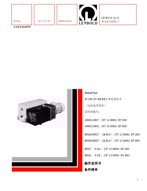
GA/ET-02307/8SOGEV ACSV200, SV300 BR2使用说明书(包括备件清单)适用的编号:10926/10927 : J 97 12 00001 (SV200)10930/10931 : J 97 12 00001 (SV300)95526/95527 – (JAPAN) : J 97 12 00001 (SV200)95536/95537 – (JAPAN) : J 97 12 00001 (SV300)95027 – (USA) : J 97 12 00001 (SV200)95031 – (USA) : J 97 12 00001 (SV300)操作说明书备件清单合格证的EC声明我们,LEYBOLD SA,在此郑重声明,以下规定的产品在设计、型号及流通过程中的改型方面均满足有关EEC指令的安全和健康基本要求。
如果没有我们批准而对产品做任何改变,本声明将无效。
产品结构:单级旋片泵SOGEV AC型号:UV25SV 16 – SV 25 – SV 40 – SV 65SV 100 – SV 200 – SV 300 – SV 585SV 630 – SV 750 – SV 1200和它们的改型,但不带电机交付的泵和带Eex…..电机交付的泵除外。
产品满足下述指令要求:- EEC 机械指令(89/392/EWG)和相继指令91/336/EWG- EEC 低电压指令(73/23/EWG)- EEC 电磁兼容性指令(89/336/EWG)应用协调标准:- EN 1012.1 (project 1993)292.1- EN- EN292.260204.1- EN真空泵安装和启动前,必须阅读并弄懂本使用说明书。
注意:按照最新技术标准和安全规程已经制造出SOGEV AC真空泵。
如果不能正确的安装或不能按指导正确使用,会发生危险。
在一定的运行条件下,当运转真空泵时可能出现危险状态。
如果发生这种情况,请与我们当地办事处联系。
莱宝产品手册

概述 莱宝真空阀 . . . . . . . . . . . . . . . . . . . . . . . . . . . . . . . . . . . . . . . . . . . . . . . . . . . . . . . . . . . . . . . . . . . . . . . . . . . . 3 产品 “微型”阀门 综述 . . . . . . . . . . . . . . . . . . . . . . . . . . . . . . . . . . . . . . . . . . . . . . . . . . . . . . . . . . . . . . . . . . . . . . . . . . . . . . . 6 角阀和直通阀,波纹管密封,多种驱动器 . . . . . . . . . . . . . . . . . . . . . . . . . . . . . . . . . . . . . . . . . . . . . . . . . . . . . 7 ISO - KF法兰真空阀 综述 . . . . . . . . . . . . . . . . . . . . . . . . . . . . . . . . . . . . . . . . . . . . . . . . . . . . . . . . . . . . . . . . . . . . . . . . . . . . . . . 9 DN 16 ISO-KF 到 DN 50 ISO-KF 角阀,波纹管密封,手动操作 . . . . . . . . . . . . . . . . . . . . . . . . . . . . . . . . . . . . . . . . . . . . . . . . . . . . . . . . . . . . . 10 直通阀,波纹管密封,手动操作 . . . . . . . . . . . . . . . . . . . . . . . . . . . . . . . . . . . . . . . . . . . . . . . . . . . . . . . . . . . 11 角阀,波纹管密封(电磁)气动 . . . . . . . . . . . . . . . . . . . . . . . . . . . . . . . . . . . . . . . . . . . . . . . . . . . . . . . . . . . 12 直通阀,波纹管密封(电磁)气动 . . . . . . . . . . . . . . . . . . . . . . . . . . . . . . . . . . . . . . . . . . . . . . . . . . . . . . . . . 14 角阀和直通阀,电磁操作 . . . . . . . . . . . . . . . . . . . . . . . . . . . . . . . . . . . . . . . . . . . . . . . . . . . . . . . . . . . . . . . . 16 ISO - K法兰真空阀 综述 . . . . . . . . . . . . . . . . . . . . . . . . . . . . . . . . . . . . . . . . . . . . . . . . . . . . . . . . . . . . . . . . . . . . . . . . . . . . . . 18 DN 63 ISO-K 到 DN 160 ISO-K 角阀,波纹管密封 手动操作 . . . . . . . . . . . . . . . . . . . . . . . . . . . . . . . . . . . . . . . . . . . . . . . . . . . . . . . . . . . . . . . . . . . . . . . . . . . 19 电磁气动操作. . . . . . . . . . . . . . . . . . . . . . . . . . . . . . . . . . . . . . . . . . . . . . . . . . . . . . . . . . . . . . . . . . . . . . . . 21 DN 250 ISO-K 角阀,波纹管密封,电磁气动操作 . . . . . . . . . . . . . . . . . . . . . . . . . . . . . . . . . . . . . . . . . . . . . . . . . . . . . . . . . 23 DN 400 到 DN 1000 大角阀 . . . . . . . . . . . . . . . . . . . . . . . . . . . . . . . . . . . . . . . . . . . . . . . . . . . . . . . . . . . . . . . . . . . . . . . . . . . . . . 25 ISO - KF / ISO - K / CF 法兰真空阀 综述 . . . . . . . . . . . . . . . . . . . . . . . . . . . . . . . . . . . . . . . . . . . . . . . . . . . . . . . . . . . . . . . . . . . . . . . . . . . . . . 27 DN 10 ISO-KF 到 DN 40 ISO-KF or ISO-K SECUVAC真空安全阀 . . . . . . . . . . . . . . . . . . . . . . . . . . . . . . . . . . . . . . . . . . . . . . . . . . . . . . . . . . . . . . . . . . . 28 抗干扰抑制套件. . . . . . . . . . . . . . . . . . . . . . . . . . . . . . . . . . . . . . . . . . . . . . . . . . . . . . . . . . . . . . . . . . . . . . . . 30 泄压阀 . . . . . . . . . . . . . . . . . . . . . . . . . . . . . . . . . . . . . . . . . . . . . . . . . . . . . . . . . . . . . . . . . . . . . . . . . . . . . . 31 断电破空阀,电磁 . . . . . . . . . . . . . . . . . . . . . . . . . . . . . . . . . . . . . . . . . . . . . . . . . . . . . . . . . . . . . . . . . . . . . . 32 粗调可变漏率阀,无隔离阀. . . . . . . . . . . . . . . . . . . . . . . . . . . . . . . . . . . . . . . . . . . . . . . . . . . . . . . . . . . . . . . 33 带隔离阀的可变漏率阀 . . . . . . . . . . . . . . . . . . . . . . . . . . . . . . . . . . . . . . . . . . . . . . . . . . . . . . . . . . . . . . . . . . . 34 破空阀 手动操作 . . . . . . . . . . . . . . . . . . . . . . . . . . . . . . . . . . . . . . . . . . . . . . . . . . . . . . . . . . . . . . . . . . . . . . . . . . . 35 电磁气动操作. . . . . . . . . . . . . . . . . . . . . . . . . . . . . . . . . . . . . . . . . . . . . . . . . . . . . . . . . . . . . . . . . . . . . . . . 36 真空锁和密封阀 . . . . . . . . . . . . . . . . . . . . . . . . . . . . . . . . . . . . . . . . . . . . . . . . . . . . . . . . . . . . . . . . . . . . . . . 37 球阀 . . . . . . . . . . . . . . . . . . . . . . . . . . . . . . . . . . . . . . . . . . . . . . . . . . . . . . . . . . . . . . . . . . . . . . . . . . . . . . 39
莱宝磁悬浮分子泵使用说明
莱宝磁悬浮分子泵使用说明真空技术**的先锋和引导者1850年莱宝公司成立1880年首台商用真空泵1905年*台旋片泵1911年*台分子泵1913年*台扩散泵1975年磁悬浮涡轮分子泵1997年中国天津工厂建立。
全球化的生产、销售及服务莱宝真空在全球拥有真空行业中较完善的销售和售后服务网络。
目前,莱宝真空在世界各地拥有20多家销售公司和30多家维修中心,并在70多个国家设有代表机构4个制造中心:莱宝法国公司,法国瓦朗斯莱宝总部德国科隆莱宝德累斯顿公司人民共和国莱宝(天津)32个销售及服务网点大于50个代理商/分销商1600名员工TURBOVAC 分子泵概述莱宝针对不同应用提供多个系列分子泵:TURBOVAC系列机械轴承分子泵;TURBOVAC MAG系列磁悬浮轴承分子泵;TURBOVAC i/iX 系列半磁悬浮分子泵(半磁悬浮分子泵仅在排气端配置脂润滑油轴承,高真空端配置免维护的永磁轴承)。
莱宝分子泵不采用润滑油轴承,既避免了对腔体产生碳氢化合物污染又能任意角度安装。
产品TURBOVAC系列半磁悬浮分子泵TURBOVAC 90 i/iX、250i/iX、(T)350i/iX和(T)450i/iX集成分子泵典型应用-分析仪器/科研--质谱仪—电子显微镜—表面分析仪—加速器和同步加速器—X射线分析仪—实验室镀膜系统—MBE--*高真空系统-生命科学—放射医疗--伽马射线灭菌--**植入物生产-工业和镀膜应用—PVD镀膜设备--光学镀膜设备—CD/DVD蓝光光碟生产—薄膜太阳能—进样室/转移室/传输室—电子束焊机—检漏/真空绝热技术特点TURBOVAC i-集成变频器,24/48V DC电源供电-切削成型转子和全新复合级设计使分子泵具有较佳性能和较大抽速,对轻质气体尤为**-任意方向安装-*高的可靠性源于**的轴承设计理念-设计灵活,适应性强-市场上一一款无油半磁悬浮分子泵-现场维护(更换轴承),维修成本低,时间短-通讯接口齐全(标配USB,RS485和15针数字I/O)TURBOVAC IX-集成真空系统控制配置灵活的通讯接口和附件控制接口(用于控制冷却单元,阀门,规管和前级泵等)-附件齐全,即插即用-适用性强,适合各类真空工艺TURBOVAC Ti,TIX-标准分子泵(不含复合级)-带气载能力强-耐粉尘-启动时间短客户得益TURBOVAC i-性价比较高-可靠性高-设计灵活性高,易于操作和与系统集成-运行成本低-抽速大,极限低-抽轻质气体(H2,He)的性能尤佳-适合与小前级泵配合使用TURBOVAC IX-配置即插即用的真空控制器-组成真空系统无需额外的控制器TURBOVAC Ti ,TiX -适合大气载应用-适合短节拍抽空应用。
莱宝LEYBOLD真空泵
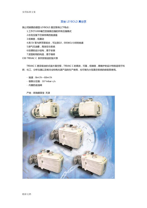
莱宝LEYBOLD真空泵我公司销售的德国LEYBOLD真空泵有以下特点:1.工作于1000毫巴至极限压强的所有压强模式2.在低压强下仍保持高的抽速值3.低噪音,低震动4.用SV泵与罗茨泵组合,可达到10,000米3/小时的抽速5.排气无油雾,高效空冷系统6.轻便的设计结构,易于安装7.坚固耐用的构造,易于维修C00 TRIVAC C 系列双级油封旋片泵TRIVAC C是双级油封式旋片真空泵,TRIVAC C的高效,可靠,低噪音,易维护的设计特别适用于科研、化工、分析仪器以及制冷业和电光源产品的生产使用,也可做为大型真空系统的前级泵使用。
- 抽速:8m3/h~60m3/h- 极限分压强:10-4mbar c/s- 内置防返油阀产地:欧瑞康莱宝天津D8C D16CD30CD40CD60CNominal Pumping Speed (50Hz) m3/h9.2519.4837.0149.4474.02Pumping Speed m3/h8.1117.0132.2442.9964.37Nominal Pumping Speed (60Hz) m3/h11.123.3944.4159.3388.82Pumping Speed m3/h9.6520.3338.6451.7872.23Ultimate Partial Pressure Without GB mbr 4×10-44×10-44×10-44×10-44×10-4Ultimate Total Pressure Without GB mbr 3×10-33×10-33×10-33×10-33×10-3Ultimate Total Pressure With GB mbr 6×10-36×10-36×10-36×10-36×10-3Water vapour tolerance mbr 30 20 40 20 25 Connecting inlet and exhaust DN KF25 KF25 KF40 KF40 KF40Noise (sound pressure level at 1m with GB closed/open(50Hz)) db54/5655/5858/658/658/6Oil filling (Max/Min) 1 1.1/0.71.5/1.03.7/3.25.0/4.45.0/4.5Weight without oil filling Kg 27 31 69 83 84Ambient temperature (Max/Min) ℃40/140/140/140/140/1Motor power 1Ph.220V.60Hz W 550 750 Total Length mm 471 560Catalog 310463105Motor power 3Ph.380V.50/60Hz W 550 750 1500 1500 2200 Total Length mm 500 540 650 760 780Catalog 3101831091311083115931158C01 TRIVAC E and B 系列双级油封旋片泵欧瑞康莱宝的TRIVAC B系列双级油封旋片泵的主要技术参数为:抽速:1.6m3/h~65m3/h 极限真空度:10-4mbar(无气镇分压强)2×10⁻³mbar(无气镇全压强)5×10⁻³mbar(带气镇全压强)耐水蒸汽能力:25mbar~40mbar欧瑞康莱宝的TRIVAC B系列双级油封旋片泵的主要特点:1、内置油泵,对泵腔进行强制润滑。
莱宝真空泵使用指导.

上海新杰办公用品管理办法一、宗旨为规范公司办公用品的采购与使用,使之既满足员工工作需要又杜绝铺张浪费,特制定本办法。
二、适用范围公司内部所有部门办公用品的采购。
三、管理部门办公用品的管理部门是运作管理部行政组,由运作管理部监管执行,采购由行政组实施采购。
四、日常管理1、办公用品分为消耗性办公用品和非消耗性办公用品。
非消耗性办公用品包括桌椅、公文柜等,同时遵守固定资产管理制度。
2、办公用品如分配为个人使用的,由个人自己负责管理,如计算器、笔类、尺类、橡皮等;如为部门业务共同使用的,由部门负责人指定专人管理。
3、公共财产发生损坏时,使用人或责任人需负相应的责任。
4、员工要爱护所有公司的公共设备,离开办公室,要检查关闭设备电源及容易发生危险的器具,保证安全。
5、任何人未经领导批准,不能将专用办公设备带出办公地点,否则一切后果自负。
五、采购管理1、办公室所有办公用品的采购工作,统一由运作管理部监管执行。
2、各部门应于每月25日至30日根据工作需要编制下月的办公用品需求计划,由行政组绘总填写《物品采购申请单》,交运作管理部进行审核及采购,具体物品发放依据实际采购情况而定。
3、办公用品采购的一般程序为:A、运作管理部定期向各个部门统计需采购物料,填写《物品采购申请单》(附表一);B、得到采购许可签字后,一般办公用品由公司制定配送公司送货上门,验收完毕后签字确认,即可在财务部核销账目;大件物品则需经过询价、议价、确定、采购、入库、发放程序,购买后凭签字核销费用。
C、将物品发放给所需部门,部门负责人在《物品领用登记表》(附表三)签字确认;D、相关领导按规定进行批准权限审签,后由财务部核销费用。
4、各部门若需采购临时急用的办公用品,由部门主管填写《物品采购申请单》(附表一),并在备注栏内注明急需采购的原因,经运作管理部审核后报总经理批准,后由运作管理部实施采购任务。
5、对单价大于______元以上物品的采购,应先进行询价、比价、议价,并将最终议定价格呈报运作管理部,经同意后方可实施采购任务。
莱宝产品手册

目录阀门与附件概述莱宝真空阀 3 产品“微型”阀门综述 6 角阀和直通阀,波纹管密封,多种驱动器7 ISO - KF法兰真空阀综述9 DN 16 ISO-KF 到DN 50 ISO-KF角阀,波纹管密封,手动操作10 直通阀,波纹管密封,手动操作11 角阀,波纹管密封(电磁)气动12 直通阀,波纹管密封(电磁)气动14 角阀和直通阀,电磁操作16 ISO - K法兰真空阀综述18 DN 63 ISO-K 到DN 160 ISO-K角阀,波纹管密封手动操作19 电磁气动操作21 DN 250 ISO-K角阀,波纹管密封,电磁气动操作23 DN 400 到DN 1000大角阀25 ISO - KF / ISO - K / CF 法兰真空阀综述27 DN 10 ISO-KF 到DN 40 ISO-KF or ISO-KSECUVAC真空安全阀28抗干扰抑制套件30 泄压阀31 断电破空阀,电磁32 粗调可变漏率阀,无隔离阀33 带隔离阀的可变漏率阀34 破空阀手动操作35 电磁气动操作36 真空锁和密封阀37 球阀39 电磁气动操作阀附件先导阀40 干扰抑制套件40 DN 250 ISO - K电磁线圈41涡轮分子泵特殊阀42 DN 16 CF 到DN 63 CFUHV全金属角阀UHV全金属角阀,两侧都带活套法兰44 UHV全金属可变漏率阀45 插板阀,配ISO - KF/CF/ISO - F法兰综述46 微型插板阀,ISO - KF,手动操作(活节杆)47 微型UHV插板阀,ISO - KF和CF手动操作(手轮)49 电磁气动操作51 HV插板阀,ISO - F手动操作53 电磁气动操作55 UHV插板阀,CF,手动操作57 UHV插板阀,电磁气动操作ISO - F法兰59 CF法兰61 法兰和真空连接件63 穿通密封接头64莱宝真空概述莱宝真空阀莱宝真空旨在通过提供各种隔离元所有应用都有以下共同要求:根据各种用途选择和设计的阀门与件和阀门满足客户与该类元件设计有关 真空保护元件体现了莱宝真空长期以来 - 轻巧地打开,振动很小 在真空工程方面的经验。
莱宝SV真空泵维护保养说明书

欧瑞康莱宝真空(天津)国际贸易有限公司SV200-SV630F型真空泵维护保养周期维护保养周期 (本周期间隔适用于正常的真空泵运行环境,对于较为恶劣的工作环境和工艺条件,维护周期间隔需作适当的缩短)维护工作间隔周期检查油位每天检查油的状态每天第一次换油150小时运转后换油每1000小时或3个月更换油过滤器每次换油时更换更换排气过滤器排气口处发现油雾时或每年清理进口过滤网视工艺条件决定检查防反油阀每年清洗热交换器每年(SV630F)清洗气镇阀过滤芯每月(SV630F)调整马达皮带半年(SV630F)维护用备件: 订货号油过滤器71018858(SV200-SV300)油过滤器71405318(SV630F)排气过滤器71064763(SV40-SV100)排气过滤器710 64 773(SV200-SV750)传动皮带71403990 (SV630F)GS77油711 17 775(20升)711 17 779(208升)莱宝真空(天津)国际贸易有限公司广州办电话: +86-20-22323985传真: +86-20-22323990邮政编码: 510650欧瑞康莱宝真空(天津)国际贸易有限公司SV200-SV300真空泵维护保养周期维护保养周期 (本周期间隔适用于正常的真空泵运行环境,对于较为恶劣的工作环境和工艺条件,维护周期间隔需作适当的缩短)维护工作间隔周期检查油位每天检查油的状态视工艺条件决定第一次换油150小时运转后换油每1000小时或3个月更换油过滤器每次换油时更换更换排气过滤器排气口处发现油雾或每年清理进口过滤网每月检查防反油阀每年检查浮阀每次更换排气过滤器或每年清理散热油管每年维护用备件: 订货号油过滤器71018858排气过滤器71064763(SV200 4个)71064773(SV300 4个)GS77油711 17 774(5升)711 17 776(25升)711 17 779(208升)欧瑞康莱宝真空(天津)国际贸易有限公司广州维修中心电话: +86-20-22323985传真: +86-20-22323990邮政编码: 510663莱宝真空(天津)国际贸易有限公司SV40-SV100真空泵维护保养周期维护保养周期 (本周期间隔适用于正常的真空泵运行环境,对于较为恶劣的工作环境和工艺条件,维护周期间隔需作适当的缩短)维护工作间隔周期检查油位每天检查油的状态视工艺条件决定第一次换油150小时运转后换油每500-1000小时或6个月更换油过滤器每次换油时更换更换排气过滤器排气口处发现油雾或每年清理进口过滤网每月检查防反油阀每年维护用备件: 订货号油过滤器71212718(SV40-SV65 1个)71213158(SV100 1个)排气过滤器71064763(SV40、SV65 1个)(SV100 2个)GS32油71117723(2升)71117724(5升)71117727(60升)GS77油711 17 774(5升)711 17 776(25升)711 17 779(208升)莱宝真空(天津)国际贸易有限公司中国天津市北辰经济开发区双海道与双辰西道交口电话: +86-22-26970808传真: +86-22-26972017邮政编码: 300400。
3B Scientific 物理实验 - 真空实验仪器说明书
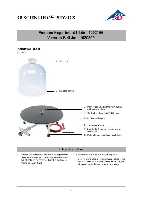
3B SCIENTIFIC ® PHYSICS1Instruction sheet09/16 ALF∙Protect the surface of the vacuum experiment plate from moisture, chemicals and mechani-cal affects to guarantee that thesystem re-mains vacuum-tight.Defective vacuum bell jars could implode.∙Before conducting experimentscheck thevacuum bell jar for any damage (entrapped air does not endanger operating safety).3 Power feed using connection cables and safety sockets4 Centre bore hole with M12 thread5 Rubber sealing disc6 4-mm safety plug7 2 cocks for hose connection and for ventilation8 Metal plate mounted on tripod stand3B Scientific GmbH ▪ Ludwig-Erhard-Str. 20 ▪ 20459 Hamburg ▪ Germany▪ Technical amendments are possible © Copyright 2023 3B Scientific GmbHVacuum experiment plate and vacuum bell jar are used to set up a vacuum chamber for experi-ments in the coarse (low) and fine vacuum range. 2.1 Vacuum Experiment PlateThe vacuum experiment plate comprises a metal plate with rubber sealing disc mounted on a tripod and two cock valves used for hose connection on the pump side as well as for ventilation. A center bore hole with M12 thread is used to secure ex-periment equipment. A vacuum-tight power feed with 4-mm safety sockets and two cables with 4-mm safety plugs are available for the power sup-ply.2.2 Vacuum Bell JarVacuum bell jar made of glass with grip knob and polished flange to be set on top of the vacuum experiment plateVacuum experiment plate Diameter: 250 mm Height: 90 mmCurrent feed-through: 2-pole with 4-mm safetysocketsPower feed: via 2 cables approx. 1 min length with 4-mm safety plugsElectrical limit specs.: max. 48 V, max. 12 A Vacuum connection: 2 hose nozzles 12 mm and 8 mm Ø Vacuum bell jar Inner diameter:: 190 mm Height:220 mmTo perform experiments the following equipment is also required:1 Rotary-Vane Vacuum Pump, Two-Stage 1003317 1 Vacuum Hose 8 mm 1002619∙ Before performing the experiment check forany damage to the vacuum bell jar.∙ Make sure that the sealing disc as well as the polished edge of the bell jar are dust-free. ∙At the start of the experiment, press the vac-uum bell jar against the plate until air pres-sure provides sufficient force against the rub-ber seal, then let the bell jar go.∙ If the handle of the valve points downwards, both cocks are closed.∙If the handle of the valve points in the direc-tion of one cock, that cock is open and the opposite cock is closed.∙After performing the experiment ventilate the chamber with the pump switched off and the evacuation valve closed.。
莱宝真空测量简易样本

Page 21
Corporate Presentation Master
Page 22
Corporate Presentation Master
热传导真空规
应用建议
– 使用时避免气体杂质沉积,会影响测量精度 – 避免震动,冲击和过强的气流,会影响使用寿命
Page 23
Corporate Presentation Master
Page 3 Corporate Presentation Master
变送器 : (带内置芯片)
命名规则: 2个字母+ 数字 (例如: TTR 91, CTR100) 优点: - 拓展性强 (温度补偿, 复合真空规……) - 可以直接和 PLC 或计算机连接工作 局限性 - 不适合辐射环境 -烘烤温度低
电离真空规
电离原理1
气体分子
=>
离子 + 电子 -
Page 27 Corporate Presentation Master
+
电离真空规
电离原理 2
+
N S
气体分子 离子 + 电子 -
-
+
-
Page 28
Corporate Presentation Master
电离真空规
结构图 PR 35
1- Flange 2- Housing 3- Anode ring 4- Ceramic 5- Electrical feed through 6- Socket 7- Anode pin 8- Cathode plate
- 量程覆盖12 个数量级: 5x10⁻¹⁰ – 1000 mbar -ITR 90 真空计复合运用热传导和电离技术 - 连续测量范围达 10E-10 到 1000 mbar -系统带有显示器可单独使用 - RS-232 C 接口
莱宝双级油封式旋片真空泵

抽 速
真空度
抽 速
真空度
当泵停止时,泵轴上的离心开关开启放空管道,将大气空气送入防返油阀的活 塞下,使防返油阀的阀盘压住进气口,将通向真空容器的管道封闭,将空气放 入泵中。 泵上的油位观察窗便于检查油位,供应的标准泵型备有单相或三相交流电机两 种。
1.2 供货没备
交货时,泵的小型法兰连接口是封闭的,标准设备供货时带有两个肩环和两个 卡箍(DN25KF 或DN40KF ) ,以便于连接进气和排气管道。
注:
1)此值由电容薄膜真空计测得。如用皮拉尼真空计测量,此值会高半个至一个数量级,此值来源于N62油。如采用其它泵油,请 与我们联系。 2)此值为三相泵的噪音,单相泵的噪音会略高。 3)选择不同的电机,泵的总长度a会略有变化。 4)其它电压、频率的电机可根据您的要求而另行配备。 5)无石棉。
GA01.800_011_02 - 11/2009 - © Oerlikon Leybold Vacuum 9
TRIVAC® C
D8C, D16C, D30C, D40C, D60C
双级油封式旋片真空泵
使用说明书 GA01.800_011_02
产品号: 310 18 310 86 311 08 311 59 311 58 及其改型
目录
页
重要安全信息
4
1 说明
5
1.1 工作原理
5
1.2 供货设备
6
1.2.1 带单相交流电机的泵
说明
GA01.800_011_02 - 11/2009 - © Oerlikon Leybold Vacuum 5
说明
1 泵体 2 转子 3 定位销 4 进气通道 5 防返油阀 6 尘粒过滤网 7 进气口 8 气镇阀帽 9 排气口 10 二次空气注入口(消音) 11 油过滤器 12 排气阀 13 排气通道 14 气镇通道 15 进油嘴 16 叶片
真空规管中文手册

带有本底照明
尺寸16.0×11.2毫米2
压强单位毫巴(缺省),乇,帕
电源
危险
真空计必须连接符合超低电压接地保护(SELV-E,按照EN 61010)要求的电源和测量仪器。连接真空计必须有保险丝。
真空计电压24伏直流(20至28伏)2)
最大纹波2 Vpp
功率损耗
120 90(法兰DN 25 ISO-KF)
120 92(法兰DN 40 CF-R)
带显示器
120 91(法兰DN 25 ISO-KF)
120 94(法兰DN 40 CF-R)
产品的件号在标牌上标明。
本公司保留对说明书不预先通知的技术更改权。
使用范围IR090用于在压强5×10⁻¹⁰…1000毫巴范围内非易燃性气体和气体混合物的真空测量。
F热阴极(灯丝)
IC离子收集极
EC电子收集极(筛网)
皮拉尼计在一定限值内气体的热导与压强有关。Pirani将这个物理现象用于压强测量。采用自调整电桥作为测量电路(见图2)。传感元件采用细的钨丝。通过适当的控制电路将丝电阻(即温度)保持不变。测量供应给丝的电功率来测量热导从而测量压强。自调整电桥的基本原理示于图2中。
1.4赔偿与保修责任如最终用户或第三方有以下情况,Leybold Inficon将不承担赔偿
与保修责任。
不理会本说明书中的要求
在不适当的状态下使用本产品
对产品作任何变动(修改,更改等)
使用不是相应产品文件中所列的附件
对所使用的过程介质,由最终用户负责。
2技术参数
测量测量范围(空气,氮,氧)5×10⁻¹⁰至1000毫巴,连续
3.2.2与其它测量仪器一起使用
BPG真空规管中文手册精编版

B P G真空规管中文手册公司内部编号:(GOOD-TMMT-MMUT-UUPTY-UUYY-DTTI-IR 090热阴极电离复合真空计使用说明书BG 804 171 BE目录产品标识有效范围使用范围工作原理注册商标1 安全1.1 使用符号1.2 人员素质1.3 一般安全规则1.4 赔偿责任与保修2 技术参数3 安装3.1 真空连接3.1.1 拆卸和安装电子学单元3.1.2 安装延伸件3.2 电源连接3.2.1 与COMBIVAC IT23一起使用3.2.2 与其它测量仪器一起使用4 运行4.1 测量原理,测量特性4.2 真空计工作原理4.3 除气4.4 显示器4.5 RS232C接口4.5.1 功能说明IR090输出IR090输入5 维护5.1 维护5.2 真空计调整5.3 真空计清洗5.4 安装障板5.5 更换障板5.6 更换规管5.7 故障查找6 拆卸7 产品返修8 附件9 备件10 废物处理附录A. 测量讯号与压强的关系B. 气体种类与压强的关系污染申报表参阅本说明书中的章节,采用符号(→XY)。
参阅其它文献,采用符号(→[Z])。
产品标识与Leybold Inficon联系时,请标明产品标牌上给出的信息。
将信息复制在标牌的复印件上。
有效范围本说明书适用于下列件号的产品不带显示器120 90 (法兰DN 25 ISO-KF)120 92 (法兰DN 40 CF-R)带显示器120 91 (法兰DN 25 ISO-KF)120 94 (法兰DN 40 CF-R)产品的件号在标牌上标明。
本公司保留对说明书不预先通知的技术更改权。
使用范围IR090用于在压强5×10⁻¹⁰…1000毫巴范围内非易燃性气体和气体混合物的真空测量。
真空计规管是SKY Smart真空计规管系列的一个组成部分。
可与COMBIVAC IT23或其它测量仪器一起工作。
工作原理在整个测量范围内,热阴极电离复合真空计有连续的测量特性。
莱宝真空泵-DOT25 DOT16使用说明书
TRIVAC ®B - DOTRotary Vane Vacuum Pump S 4B -DOT D 8B -DOTD 16B -DOT/-with float switch D 25B -DOT D 40B -DOT D 65B -DOTCat.No.104 04114 06114 10AccessoriesAF/AK 4-8-DOTAF/AK 16-25-DOT AF/AK 40-65-DOT AF/AK 40-65-DOT AR 4-8-DOTFloat switch 16 - 25Operating Instructions Spare Parts ListT R IV A C -B -D O T p um p s a n d a cc e s s o r ie s a r e e q u i pp e d w i t h s p e c i a l s e a l s w h i c h a r e c a p a b l eo f r e s i s t i n g e x p o s u r et o b r a k e f l u i d s .T h e s e pu m p s m u s t o n l y b e o p e r a t e d w i t h b r a k e f l u i d s i n a c c o r d a n c e w i t h D O T 3 a n d D O T 4 o r a l t e r n a t i v e o p e r a t i n g a g e n t s w h i c h h av e b e e n a p p r o v e d b y L e y b o l d .GA/ET 01.208/3.02 - 06/97Contents2Contents. . . . . . . . . . . . . . . . . . . . . . . . . . . . . . . .Page 1Description . . . . . . . . . . . . . . . . . . . . . . . . . .31.1Function . . . . . . . . . . . . . . . . . . . . . . . . . . . . .31.2Supplied equipment . . . . . . . . . . . . . . . . . . . .51.3Accessories . . . . . . . . . . . . . . . . . . . . . . . . . .61.4Transportation . . . . . . . . . . . . . . . . . . . . . . . .61.5Technical data . . . . . . . . . . . . . . . . . . . . . . . .72Operation . . . . . . . . . . . . . . . . . . . . . . . . . . .92.1Installation . . . . . . . . . . . . . . . . . . . . . . . . . . .92.2Connection to the system . . . . . . . . . . . . . . . .92.3Electrical connection . . . . . . . . . . . . . . . . . . .102.4Start-up . . . . . . . . . . . . . . . . . . . . . . . . . . . .112.5Operation . . . . . . . . . . . . . . . . . . . . . . . . . . .122.6Switching off/shutdown . . . . . . . . . . . . . . . . .123Maintenance . . . . . . . . . . . . . . . . . . . . . . . .133.1Checking the oil level . . . . . . . . . . . . . . . . . .143.2Oil change . . . . . . . . . . . . . . . . . . . . . . . . . .143.3Cleaning the dirt trap . . . . . . . . . . . . . . . . . .143.4Removing and fitting the internal demister . . .153.5Disassembly and reassemblyof the electric motor . . . . . . . . . . . . . . . . . . .163.6Replacing the outer shaft seal . . . . . . . . . . . .173.7Removing and remounting the pump module 183.8Leybold service . . . . . . . . . . . . . . . . . . . . . .183.9Storing the pump . . . . . . . . . . . . . . . . . . . . .193.10Maintenance plan . . . . . . . . . . . . . . . . . . . . .204Troubleshooting . . . . . . . . . . . . . . . . . . . . .225Spare parts list . . . . . . . . . . . . . . . . . . . . . .25EEC Declaration of Conformity . . . . . . . . .24Indicates procedures that must be strictlyobserved to prevent hazards to persons.Indicates procedures that must strictly be observed to prevent damage to, or destruc-tion of the equipment.FiguresThe references to figures, e.g.(1/2) consist of the Fig.No.and the Item No.in that order.Leybold ServiceIf a pump is returned to Leybold, indicate whether the pump is free of substances damaging to health or whether it is contaminated.If it is contaminated also indicate the nature of the hazard.Leybold must return any pumps without a "Declaration of Contamination" to the sender's address.Information on the pump’s operating agentThe operating agent used in the pump complies with the US standard FMVSS/116 DOT 4.Operating agents which comply with this specification may be used instead of DOT 3 and may also be mixed with DOT 3.• Store the operating agent only in its origi-nal container in a clean and dry place.Keep the container firmly sealed.• Any contamination by dirt, water, crude oil products or other materials may result in damage to the pump.• Operating agent which has been used must never be re-used.• The operating agent will attack (dissolve)paint.• When swallowing the operating agentthere is the danger of being poisoned.• Always keep the operating agent in a sea-led container and out of reach of children.Disposal of waste oilUnder the amended law relating to waste disposal dated November 1, 1986 (valid in the Federal Republic of Ger-many) the disposal of used oil is subject to new provi-sions.According to legislation relating to waste disposal the so-called principle of causality is applied.Hence,anyone in possession of used oil is responsible for its proper disposal.Used oils coming from vacuum pumps must not be mixed with other substances.Used operating agents must be disposed of separately and in accordance with the regulations.Operating agents from vacuum pumps that have been contaminated by other substances must be labelled, sto-red and disposed of as special waste with reference to the kind of contamination.Waste disposal key:+ 55256 xIn many countries proof of were the operating agent has finally been left is required by Law and often shipping of such contaminated waste requires permission by the authorities.Waste disposal information is available through:Bundesamt für Gewerbliche Wirtschaft (BAW)Frankfurter Str.29-31D-65760 Eschborn/T aunus Phone:+ 49 (0)6196 4041T elefax:+ 49 (0)6196 404212Warning CautionWarning CautionGA/ET 01.208/3.02 - 06/97Description31DescriptionTRIVAC-B-DOT pumps are oil-sealed rotary vane pumps having either a single stage or two stages.The number in the type designation indicates the pumping speed in m 3x h -1.TRIVAC-B-DOT pumps can pump gases and vapours.They are used to evacuate brake systems and to degas hydraulics liquids.The drive motor of the TRIVAC-B-DOT is directly flanged to the pump at the coupling housing.The pump and motor shafts are directly connected by a flexible cou-pling.The bearing points of the pump module are force lubricated sliding bearings.All controls as well as the oil-level glass and the nameplate are arranged on the front.All connections are to be found at the sides of the pump.The oil-level glass is provided with prisms for better observation of the oil level.The pump module consists of assembly parts which are pin-fitted so as to allow easy disassembly and reassem-bly.The pump module can be easily removed without special tools.TRIVAC-B-DOT pumps are equipped with special seals capable of resisting brake fluids.1.1FunctionThe rotor (2/7), mounted eccentrically in the pump hou-sing (2/6), has two radially sliding vanes (2/5) which divi-de the pump chamber into several compartments.The volume of each compartment changes periodically with the rotation of the rotor.As a result, gas is sucked in at the intake port (2/1).The gas passes through the dirt trap sieve (2/2), flows past the open anti-suckback valve (2/3) and then enters the pump chamber (2/6).In the pump chamber, the gas is passed on and compressed, after the inlet aperture is closed by the vane.The operating agent injected into the pump chamber is used for sealing and lubricating.The slap noise in the pump which usually occurs when attaining the ultimate pressure is prevented by admitting a very small amount of air into the pump chamber.The compressed gas in the pump chamber is ejected through the exhaust valve (2/10).The operating agent entrained in the gas is coarsely trapped in the internal demister (2/11);there the operating agent is also freed of mechanical impurities.The gas leaves the TRIVAC-B-DOT through the exhaust port.During compression, a controlled amount of air - the so-called gas ballast - can be allowed to enter the pump chamber by opening the gas ballast valve.The gas bal-last stops condensation of vapours in the pump chamber up to the limit of water vapour tolerance as specified in the technical data for the pump.CautionGA/ET 01.208/3.02 - 06/97The gas ballast valve is opened and closed by turning the gas ballast knob (7/5) on the front.T o enable the TRIVAC-B-DOT to be used at intake pres-sures as high as 1,000 mbar, a special lubricating system was developed featuring force-lubrication of the sliding bearings.A pump (3/6) for the operating agent pumps the opera-ting agent from the reservoir (3/5) into a pressure-lubri-cation system which supplies all bearing points (3/2).From there the operating agent enters the pump cham-ber area (2/6) of the vacuum pump.The pump for the operating agent is fitted in the front end plate on the coupling side of the pump module.The suc-tion line for the operating agent is placed low, resulting in a large usable reservoir.The operating agent is separated from the gas in the TRIVAC-B-DOT in two steps as described above.First,small droplets are coalesced into large drops in the inter-nal demister (2/11) fitted above the exhaust valve (2/10).These are then returned by deflection at the chamber wall of the volume for the operating agent back to the reservoir for the operating agent.This and the large usa-ble reservoir for the operating agent ensure long inter-vals between operating agent changes even at high inta-ke pressures.DescriptionThe vacuum is maintained by the TRIVAC-B-DOT by an integrated hydropneumatic anti-suckback valve (2/3)which is controlled via the pressure of the operating agent.During operation of the TRIVAC-B-DOT the control piston (4/3) remains sealed against a spring (4/2) by the pressure of the operating agent.The valve disc (4/6) of the anti-suckback valve is held at the lower position by its own weight (valve open).When the pump stops (becau-se it has been switched off or because of a failure), the pressure of the operating agent drops and the spring (4/2) presses the control piston (4/3) up.Thus a connec-tion is provided between the case for the operating agent or the reservoir (4/1) for the operating agent and the piston (4/4) of the anti-suckback valve.Due to the pres-sure difference between the case of the operating agent and the intake port, the operating agent presses the piston (4/4) up and the valve plate (4/6) against the valve seat (4/5).The quantity of operating agent in the reser-voir (4/1) prevents the entry of air into the intake port (2/1) at the beginning of this process.After the operating agent has flowed out from the reser-voir and when the valve plate rests on the valve seat, air follows in, which vents the pump chamber and forces the valve disc (4/6) against its seat.This effectively prevents backstreaming of any operating agent or its vapours.The anti-suckback valve (2/3) operates independently of the operating mode of the pump, i.e.also with gas ballast.4GA/ET 01.208/3.02 - 06/97Description1.2Supplied EquipmentThe TRIVAC-B-DOT is delivered with the following basic equipment:•Pump with all-metal motor;all external plastic parts have been replaced by metal parts,• Pump filled with brake fluid according to DOT 4,• 1 centering ring,• 1 centering ring with dirt trap, • 2 clamping rings.As protection during shipment, the connection ports are each blanked off by shipping seals.5TRIVAC-B-DOT pumps with single-phase AC motor are supplied ready to operate with switch, built-in thermal motor protection switch, mains cable (2 m) and mains plug.For TRIVAC-B-DOT pumps with three-phase AC motor,the switch, motor protection switch, mains cable etc.are not included.Fig.4 Hydropneumatic anti-suckback valveKey to Fig.41Reservoir for the operating agent 2Spring 3Control piston 4Anti-suckback piston5Valve seat 6Valve disk 7Gas inletDescription1.3AccessoriesCat.No. Exhaust filter AF 16-25 DOT . . . . . . . . . . . . . . .124 16 Exhaust filter AF 4-8 DOT . . . . . . . . . . . . . . . . .124 14Condensate trap AK 16-25 DOT . . . . . . . .upon request Condensate trap AK 4-8 DOT . . . . . . . . . .upon request Exhaust filter AF 40-65 DOT . . . . . . . . . .upon request AR 16-25 DOT . . . . . . . . . . . . . . . . . . . . .upon request Float switch for all models . . . . . . .Ref.No.200 39 838 FE 40 - 65 for AF 40 - 65 . . . . . . . .Ref.No.200 39 840Only use the kind of operating agent speci-fied by Leybold.Alternative types of opera-ting agent are specified upon request.1.4Transportation•Pumps which are filled with operatingagent must only be moved while standingupright.Otherwise operating agent mayescape.Avoid any other orientations during trans-port.• Check the pump for the presence of anyoperating agent leaks, since there existsthe danger that someone may slip on spiltoperating agent.• When lifting the pump you must make useof the crane eyes provided on the pumpfor this purpose;also use the recommen-ded type of lifting device.6GA/ET 01.208/3.02 - 06/97 CautionCautionWarningGA/ET 01.208/3.02 - 06/97Description7* as per DIN 28 400 and following numbers1)Weight for the version with three-phase motor220-240/380-420 V , 50 Hz 240-265/415-460 V , 60 Hz1.5Technical DataWe can only guarantee that the pump will meet its specifications when using the type of lubricant which has been specified by us.CautionGA/ET 01.208/3.02 - 06/97Description8Operation2.1InstallationTRIVAC-B-DOT pumps must only be ope-rated in connection with brake fluid fil-ling and degassing systems.The TRIVAC-B-DOT pump can be set up on a flat, hori-zontal surface.Rubber feet under the coupling housing ensure that the pump can not slip.If you wish firmly install the TRIVAC-B-DOT in place, ins-ert bolts through bore holes in the rubber feet.Max.tilt for the pump (without furtherattachment) with possibly fitted standardaccessories is 10°from the vertical.The rubber feet act as vibration absorbers.They must therefore not be compressed byscrews.When installing the TRIVAC-B-DOTpump, make sure that the connections andcontrols are readily accessible.The site chosen should allow adequate aircirculation to cool the TRIVAC-B-DOT (keepfront and rear unobstructed).The ambienttemperature should not exceed+ 40 °C (104 °F) and not drop below+ 12 °C (55 °F) (see Section 2.5.3).The max.amount of heat given off approxi-mately corresponds to the rated motorpower.2.2Connection to theSystemBefore connecting the TRIVAC-B-DOT, remove the ship-ping seals from the connection flanges (7/2) and (7/3).Retain the shipping seals in case you needto store the pump in the future.The pump is shipped with intake and exhaust flanges mounted for horizontal connection of the connecting lines.Y ou can easily convert the ports for vertical connection by removing the four capscrews, rotating the flanges as required, and reinstalling the capscrews. Connect the intake and exhaust lines with a centering ring and a clamping ring e the centering ring with the dirt trap for the intake port.Connect the intake and exhaust lines using anti-vibration bellows, without placing any strain on the pump.The intake line must be clean.Deposits in the intake line may outgas and adversely affect the vacuum.The connecting flanges must be clean and undamaged. The maximum throughput of the pump is equivalent to the pumping speed of the pump (see Section 1.5).92OperationCaution CautionCautionGA/ET 01.208/3.02 - 06/97OperationThe cross-section of the intake and exhaust lines should be at least the same size as the connection ports of the pump.If the inta-ke line is too narrow, it reduces the pumping speed.If the exhaust line is too narrow,overpressures may occur in the pump;this might damage the shaft seals and cause leaks.The maximum pressure in the case for the operating agent must not exceed 1.5bar (absolute).When pumping vapours, it is advisable to install condensate traps on the intake and exhaust sides.Install the exhaust line with a downward slope (lower than the pump) so as to pre-vent condensate from flowing back into the pump.If this is not possible, insert a con-densate trap.The exhaust gases from the vacuum pump must be safely led away and subjected to post-treatment as required.In order to redu-ce the emission of operating agent vapours we recommend the installation of an addi-tional exhaust filter (Leybold accessory).Depending on the type of application or the kind of pumped media, the corresponding regulations and information sheets must be observed.Never operate the pump with a sealedexhaust line.There is the danger of injury.The exhaust gases coming from the vacu-um pump must be lead away safely and subjected to suitable post treatment as required.Before starting any work on the pump, the personnel must be informed about possible dangers first.All safety regulations must be observed.2.3Electrical ConnectionBefore wiring the motor or altering thewiring, ensure that mains supply for the pump is off and that it can not be applied inadvertently.In order to prevent the pump from running up unexpectedly after a mains power failu-re, the pump must be integrated in the con-trol system in such a way that the pump can only be switched on again manually.This applies equally to emergency cut-out arran-gements.Electrical connections must only be done by a qualified electrician as defined by VDE 0105 in accordance with the VDE 0100 gui-delines.Observe all safety regulations.TRIVAC-B-DOT pumps are available with a single-phase or a three-phase AC motor.2.3.1Pump with Single-Phase AC MotorPumps equipped with a single-phase AC motor may be connected directly to the mains via the mains cord and the mains plug.At 230 V use at least a 6 A slow-blow or a 10 A fast-blow fuse.The direction of rotation need not be checked as it is fixed.The motor is protected against overloading by a thermal overload switch with automatic resetting.If the thermal overload protector shuts offthe pump, the motor will restart itself as soon as it cools.That's why the mains plug should be disconnected from the mains before starting with any work on the pump.2.3.2Pump with Three-Phase AC MotorTRIVAC-B-DOT pumps with a three-phase motor are supplied without accessories for electrical connection.They must be connected via the appropriate cable, and a suitable motor protection switch.Set the switch in accordance with the rating on the motor nameplate.Fig.8 shows the connection for pumps with 230/400 V ,50 Hz motors.Please also observe the motor wiring dia-gram in the junction box and the information given on the nameplate of the motor.10GA/ET 01.208/3.02 - 06/97Warning Warning CautionWarningOperation After connecting the motor and after everytime you alter the wiring, check the directionof rotation.To do so, briefly switch on themotor and check whether a suitable cover(e.g.a blank flange) is sucked in at the inta-ke port.If not, interchange two phases ofthe connection.Observe the direction arrow on the couplinghousing.2.4Start-upTRIVAC-B-DOT pumps must only be ope-rated in connection with brake fluid fil-ling and degassing systems.Do not select a degassing pressure of lessthan 1 mbar, since at this pressure volatilesubstances in the brake fluid may escapeand damage the elastomer seals of thepump.Each time before starting up check the level of the ope-rating agent.For pumps with 3-phase motors, check the direction ofrotation before starting the pump for the first time andafter each change in the electrical connection (see Sec-tion 2.3.2).On initial start-up, after prolonged idle periods or afterhaving changed the operating agent, the specified ulti-mate pressure cannot be attained until the operatingagent has been degassed.This can be done by runningthe pump for approx.30 min.with the intake line closedand the gas ballast valve (7/5) open.Before starting the pump ensure that thepump and the fitted accessories meet therequirements of your application and thatsafe operation can be guaranteed.Avoid exposure of any part of the body tothe vacuum.There is the danger of injury.Never operate the pump with an open inta-ke port.Vacuum connections as well as oil-fill and oil-drain openings must never beopened during operation.The safety regulations which apply to theapplication in each case must be observed.This applies to installation, operation andduring maintenance (service) as well aswaste disposal and transportation.The standard pump is not suited for pum-ping of hazardous gases or vapours.Our technical sales department is available for furtheradvice in these matters.2.4.1Areas of ApplicationThe pump is not suitable for pumping of:- ignitable and explosive gases or vapours,- oxidants,- pyrophorous gases.The pumps are not suitable for pumping ofliquids or very dusty media.Suitable protec-tive devices must be installed.Our technical sales department is available for furtheradvice in these matters.8 Connection diagram for TRIVAC-B-DOT with 50 Hz 3-phase motorDelta connection Star connectionCautionWarningWarningCautionWarningCautionOperation2.5OperationTRIVAC-B-DOT pumps can pump condensable gases and vapours, provided that the gas ballast valve (7/15) is open and the pump has attained its operating tempera-ture.2.5.1Pumping of Non-CondensableGasesIf the process contains mainly permanent gases, the pump may be operated without gas ballast, provided that the saturation vapour pressure at operating temperature is not exceeded during compression.If the composition of the gases to be pumped is not known and if condensation in the pump cannot be ruled out, run the pump with the gas ballast valve open in accordance with Section 2.5.2.2.5.2Pumping of Condensable Gases andVapoursWith the gas ballast valve open and at operating tempe-rature, TRIVAC-B-DOT pumps can pump pure water vapour up to the water vapour tolerance specified by the technical data.If the vapour pressure increases above the permissible level, the water vapour will condense in the oil of the pump.When pumping vapours ensure that the gas ballast valve is open and that the pump has been warmed up for approximately 30 minutes with the intake line closed.Vapour phases may only be pumped up tothe permissible limit after the pump hasattained its operating temperature.During pumping, vapours may dissolve inthe oil.This changes the properties of theoperating agent and thus there is a risk ofcorrosion in the pump.Therefore, don'tswitch off the TRIVAC-B-DOT immediatelyafter completion of the process.Instead,allow the pump to continue operating withthe gas ballast valve open and the intakeline closed until the operating agent is freeof condensed vapours.We strongly recom-mend operating the TRIVAC-B-DOT in thismode for about 30 minutes after completionof the process.In cyclic operation, the TRIVAC-B-DOT should not be switched off during the intervals between the individual working phases (power consumption is minimal when the pump is operating at ultimate pressure), but should continue to run with gas ballast valve open and intake port closed (if possible via a valve).Once all vapours have been pumped off from a process (e.g.during drying), the gas ballast valve can be closed to improve the attainable ultimate pressure.2.5.3Operating TemperatureProper operation of the TRIVAC-B-DOT is ensured in the ambient temperature range between 12 °C to 40 °C (55°F to 104 °F).At operating temperature, the surface temperature of the TRIVAC-B-DOT may lie between 40 °C and over 80 °C (104 °F and 176 °F), depending on the load.The surface temperature of the TRIVAC-B-DOT pumps may rise above 80 °C.There isthe danger of receiving burns.2.6Switching Off/ShutdownUnder normal circumstances, all that you need do is to electrically switch off the TRIVAC-B-DOT.For longer standstill periods you must sealthe pump so that no humidity can enterbecause brake fluid is hygroscopic.No further measures will be required.When pumping condensable media let the pump conti-nue to operate with the gas ballast valve open and the intake line closed before switching off (see Section 2.5.2).When pumping aggressive or corrosive media, let the pump continue to operate even during long non-working intervals (e.g.overnight) with the intake line closed and the gas ballast valve open.This avoids corrosion during idle periods.If the TRIVAC-B-DOT is to be shutdown for an extended period after pumping aggressive or corrosive media or if the pump has to be stored, proceed as follows:After pumping of pumping harmful sub-stances, take adequate safety precautions. Our technical sales department is available for further advice in this matter.WarningWarningCautionCautionMaintenanceDrain the operating agent (see Section 3.2).Add clean operating agent until the level is at the "min"mark (see Section 3.2) and let the pump operate forsome time.Then drain the operating agent and add clean operating agent until the level is at the "max" mark (see Section 3.2).Seal the connection ports.Special conservation or anti-corrosion oils aren't necessary.Please also take note of the informationgiven in Section 3.9 (Storing the Pump). 2.6.1Shut-Down through MonitoringComponentsWhen the pump has been switched off dueto overheating sensed by the motor coil pro-tector, the pump must only be startedmanually after the pump has cooled downto the ambient temperature and after havingremoved the cause first.2.6.2Failure of the Control System or theMains PowerIn order to prevent the pump from runningup unexpectedly after a mains power failu-re, the pump must be integrated in the con-trol system in such a way that the pump canonly be switched on again manually.Thisapplies equally to emergency cut-out arran-gements.3MaintenanceDisconnect the electrical connections befo-re disassembling the pump.Make absolute-ly sure that the pump cannot be acciden-tally started.If the pump has pumped harmful sub-stances, contrary to what has been statedin Section 2.4, ascertain the nature ofhazard and take adequate safety measu-res.Observe all safety regulations.If you send a pump to LEYBOLD for repair please indi-cate any harmful substances existing in or around thepump.A form is available from LEYBOLD for this purpo-se.When disposing of used oil, you mustobserve the applicable environmental regu-lations!Due to the design concept, TRIVAC-B-DOT pumpsrequire very little maintenance when operated under nor-mal conditions.The work required is described in thesections below.In addition to this, a maintenance plan isprovided in Section 3.10.All work must be carried out by suitably trai-ned personnel.Maintenance or repairs car-ried out incorrectly will affect the life andperformance of the pump and may causeproblems when filing warranty claims.Formore information please contact the Ley-bold Service.If the TRIVAC-B-DOT is used in ambient airwhich is much contaminated, make surethat the air circulation and the gas ballastvalve are not adversely affected.CautionCautionCautionWarningWarningWarningMaintenance3.1Checking the Oil Level During operation of the TRIVAC-B-DOT the level of the operating agent must always remain between marks (9/2) and (9/3) on the level glass.The amount of opera-ting agent must be checked and topped up as required.Fill in operating agent only after the pumphas been switched off.3.2Oil ChangeFor proper operation of the pump, it is essential that the pump has an adequate supply of the correct and clean operating agent at all times.The operating agent must be changed when it looks dirty or if it appears chemically or mechanically worn out. The operating agent should be changed after the first 100 operating hours and then at least every 2,000 to 3,000 operating hours or after one year.At high intake pressures and intake temperatures and/or when pum-ping contaminated gases, the operating agent will have to be changed much more frequently.Further changes of the operating agent should be made before and after long-term storage of the pump.If the operating agent becomes contaminated too quick-ly, install a dust filter and/or a filter for the operating agent (see Section 1.3).Contact us for more information in this matter.Only change the operating agent after thepump has been switched off and while thepump is still warm.Required tool:Allen key 8 mm.Remove the drain plug (9/4) for the operating agent and let the used operating agent drain into a suitable contai-ner.When the flow of operating agent slows down, screw the drain plug for the operating agent back in, briefly switch on the pump (max.10 s) and then switch it off again.Remove the drain plug for the operating agent once more and drain out the remaining operating agent. Screw the drain plug for the operating agent back in (check the flat gasket and reinstall a new one if neces-sary).Remove the fill plug (9/1) for the operating agent and fill in fresh operating agent.Screw the fill plug (9/1) for the operating agent back in.If there is the danger that the operatingagent may present a hazard in any waybecause of the media which have beenpumped, you must determine the kind ofhazard and ensure that all necessary safetyprecautions are taken.We can only guarantee that the pump ope-rates as specified by the technical data ifthe lubricants recommended by us areused.3.3Cleaning the Dirt TrapA wire-mesh sieve is located in the intake port of the pump to act as a dirt trap for coarse particles.It should be kept clean to avoid a reduction of the pumping speed. For this purpose, remove the dirt trap (2/2) from the inta-ke port and rinse it in a suitable vessel with solvent.Then thoroughly dry it with compressed air.If the dirt trap is defective, replace it with a new one.The cleaning intervals depend on the appli-cation.If the pump is exposed to large amo-unts of abrasive materials, a dust filtershould be fitted into the intake line.9 Exchanging the operating agentKey to Fig.9Plug for filling in the operating agentOperating agent level mark maximumOperating agent level mark minimumPlug for draining out the operating agentCautionWarning 1 2 3 4CautionCautionCaution。
莱宝真空泵使用指导
²¢ÇëÈçÇë停泵时由于工作状态不同进入泵不同停泵时油位低于最小量请不要担心请在泵运转时比较油位最大量最小量此泵油位电源线连接不正确供给电机的电源电压与电机不匹配电机发生故障泵油10泵油太粘稠排气过滤器或排气管道被堵塞因抽入大量杂物导致泵被卡死电源线连接不正确检修由专业电工检查维修电源线机保护开关确靠注意关换任意两个相线的连接供给电机的电源电压与电机不匹配检修例D60C某款电机铭牌如下其所供电源应为电机发生故障检修泵油温度10检修加热泵和泵油或是用别的类型的泵油亦可打开泵的进气口手工点动运转泵注意点动每次时间不要超10»·¾³ÖÐÖÂʹ±Ã10当开泵时由于泵困难长运转如不及时关机毁泵油太粘稠检修换油使用造成粘度变稠质法需毫米总是在泵关断电源但仍是温热的情况下换油卸下放油塞将用过的油排放入适当的容器中当油的流动减拧塞最多秒再源慢时短暂地开动泵将放油塞拧上如卸下放油塞放空剩余的油检查垫片则更换注入适量新油排气过滤器或排气管道被堵塞检修排气过滤器的使用排气管道的清洗因抽入大量杂物导致泵被泵被卡死检修动风扇如果转不动说明泵已卡死如泵在运转中发现电机风扇不转电机过热测量方法或规管不合适外部泄漏防返油阀失效排气阀故障泵油不合适进气口被污染泵的抽速太小测量方法或规管不合适检修使用正确的测量方法及规管规管安装位置原则上应尽可能的把规管安装在接近被测量的部位但是当测量系统时真空系统中影响测量的因素很多有时在规管与被测容器之间连接管道成测量误差规管安装方法对于没有定向气流的静态平衡真空系统对规管的安装无特殊要求”¼´°²×°¹æ¹Üʱ¹æ¹Ü½øÆø¿Ú·½ÏòÓ¦ÓëÕæ¿Õ¹ÜµÀÄÚµÄÆøÁ÷·½Ïò´¹Ö±Ñ¡ÔñÕæ¿Õ¼ÆÔ-ÔòÔÚÒªÇóµÄ¾«¶È±»²âÆøÌå¶Ô¹æ¹ÜµÄÓ°ÏìÈçºÎ¿ÉУ׼Ëù²âΪȫѹ»¹ÊÇ·ÖѹÁéÃô¶ÈÓëÆøÌåÖÖÀàÓйطñ·´Ó¦Ê±¼ä³¤¶Ì) 稳性复现性可看真空计的安装方法保修操能规格泵外部泄漏检修防返油阀失效检修清洗或维修防返油阀染造成停泵时不器保持真空排气阀故障检修维修排气阀间有杂质排气口封不严间有杂质排气口没有被封住泵油不合适检修入可凝性气体进气口被污染检修清洗抽气管道抽气管道的清洗请适的溶剂清洗并使之干成泵油污染泵的抽速太小检修统请根据系统参数选用泵进气口的杂物捕集器被堵塞排气过滤器被堵塞连接真空管直径太小或管道太长被抽容器或连接管道存在大的漏点进气口的杂物捕集器被堵塞检修清洗捕集器或更换滤网预防在进气口前安装一个杂物过滤器排气过滤器被堵塞检修更换过滤芯法用开过滤器外壳用8毫米更换连接真空管直径太小或管道太长检修使用直径足够大的管道或短的连接管道被抽容器或连接管道存在大的漏点检修检查被抽容器或管道真空系统有泄漏防返油阀故障真空系统有泄漏检修对系统进行检漏防返油阀故障检修维修防返油阀请保证防返油阀表面的清洁清洗时请避免损伤阀面防返油阀阀面破损造连的容器保持真空染相连的容器保持真空冷却泵所需的风受阻泵工作的环境温度太高所抽气体的温度太高油位太低油不合适泵油的循环受阻排气过滤器或排气管道被堵塞排气阀故障泵腔被磨损冷却泵所需的风受阻正确的安装检修电机后部应留足够的空间间过小造成通风不畅泵工作的环境温度太高检修降低环境温度最高允许环境温度40热原因造温度过高所抽气体的温度太高检修改变工艺油位太低检修加油请确认泵在运转时在正常运转时油位低于最小量从位实际位置泵油不合适检修换油正常油的颜色为清亮半透明的黄色泵油老化裂解不适于工艺要求造泵油的循环受阻检修清洗或维修进油嘴在泵运转时泵腔进油嘴被堵塞后造成泵在运行中温度过高排气过滤器或排气管道被堵塞检修排气过滤器的使用排气管道的清洗排气阀故障检修联系我们维修排气阀间有杂质排气口封不严间有杂质排气口没有被封住泵腔被磨损检修磨损更换泵腔部件泵的油箱内有过压油来自真空系统防返油阀失效防返油阀的密封面磨损或太脏油位过高泵的油箱内有过压发生原因停泵后且防返油阀失效检修请保证泵的排气管道的通畅如安装排气过滤器请定期检查或更换过滤芯如果您的系统中存在多台泵共用一根排气管道的情况请在每一台的排气管道处安装单向阀片并在总排气管道的出口安装排风机来保证泵的排气的通畅注意必须保证泵的出气口油来自真空系统检修检查真空系统防返油阀失效检修清洗或维修防返油阀染造成停泵时不器保持真空防返油阀的密封面磨损或太脏检修清洗或维修进气口和防返油阀染造成停泵时不器保持真空油位过高检修放出多余的油请确认泵在运转时在正常运转时油位超过最大量从位实际位置可凝性气体凝结检修对油进行脱气或换油并冲洗泵腔打开气镇阀运转或在入口处安装冷凝捕集器排气预防无论如何管道安装时应坡度向下油位太低消音孔被堵塞进气口压强太高内部油雾过滤器被堵塞弹性连轴体磨损叶片或轴承损坏油位太低检修加油请确认泵在运转时在正常运转时油位低于最小量从位实际位置消音孔被堵塞”检修清洗或更换消音部件消音孔位置进气口压强太高检修降低进气口压强小噪音降低进气入口气体流量内部油雾过滤器被堵塞检修清洗或更换油雾过滤器可见到油雾过滤器音过大旧新弹性连轴体磨损检修更换一个新的联轴体体对称的。
高二历 Two-Channel Gas Controller 产品说明书

Specifications subject to change without notice. | USA 210203 | Page 1 of 5Two-Channel Gas ControllerDESCRIPTIONHighly configurable, UL 2075 performance-tested and -certified, and wall-mounted gas monitor; continuously compares measured inputs to pre-defined alarm thresholds and activates internal switches/relays when thresholds are breached.Includes inputs for two external 4-20 mA analog sensor/transmitters, one binary input, two alarm relays, two open collector outputs and one analog output. Up to four thresholds can be defined for each input.Controller also includes a large, 2-line, 16-character LCD and four pushbuttons for an easy system configuration (with password protection) and continuous real-time measurement value display.Four faceplate LEDs indicate power, alarms, manual relay override and sensor fault conditions.Programmable “service date” alarm ensures reliable long-term operation.APPLICATIONTo detect and control levels of toxic and combustible gases in a wide variety of commercial and industrial applications; for example, carbon monoxide (CO) and nitrogen dioxide (NO 2) levels in parking structures, warehouses and repair shops, methane in boiler rooms, hydrogen in battery charging rooms, refrigerant leaks in chiller rooms, and more using INTEC AT-Series gas transmitters. Analog input channels can also measure/monitor any other environmental conditions (such as temperature, relative humidity, static pressure, etc.) using industry-standard 2-wire or 3-wire 4-20 mA transmitters.Setup options provide for selectable latching or non-latching alarms, time delays and threshold hysteresis to eliminate false trips and resets, as well as minimum relay on/off times to prevent harmful fan cycling.The controller can communicate with most building automation, DDC, PLC or analog control systems via binary/analog output signals.FEATURES• Continuous monitoring and four-stage control• Two (2) remote analog inputs, 4-20 mA, overload & short-circuit protected• One (1) analog output, (0)4-20 mA / (0)2-10 VDC- Selectable for lowest, highest, or average of the two analog inputs • One (1) digital input • Two (2) relay outputs:- (1) SPDT, (1) SPST-NO/NC • One (1) 24 VDC switched output, 50 mA max.• Audible Alarm• Liquid Crystal Display (LCD)• LED status indicatorsPolyGard MGC3• Keypad user interface • Simple menu-driven programming• Modular technology for easy installation & maintenance• NEMA 4X (IP65) enclosureNRTL Performance Tested & CertifiedConforms to STD UL 2075SPECIFICATIONSElectricPower supply 24 VAC/VDC, -20%/+15%50/60 Hz,reverse polarity protectedPower consumption 2.5 VA (0.1 A)Type of ControlGeneral Four-stage (S1 to S4) control,assignable up to two (2) binary/relay and 24 VDC / 50 mAswitched outputs, i.e. low-highstage for relay output andswitched 24 VDC at any stage forremote alarmingStage level / setpoint Field adjustable over full range,four (4) stages (S1 to S4) peranalog input, assignable tocurrent or mean (average) value - each stage level (S1-S4) Assignable to any relay- sensor fail-safe Assignable to any stage level- hysteresis/switching differential Selectable for each sensor point Inputs/OutputsGas / Input types- CO Carbon Monoxide- EX Explosive (%LEL)- NO Nitrogen Oxide- NO2Nitrogen Dioxide- O2< Oxygen (low alarms)- O2> Oxygen (high alarms)- NH3Ammonia- CO2Carbon Dioxide- SO2Sulfur Dioxide- H2S Hydrogen Sulfide- CL2Chlorine- ETO Ethyl Alcohol- VOC Vol. Organic Compounds- R4XX Refrigerants- R5XX Refrigerants- R123 Refrigerants- R134A Refrigerants- R22 Refrigerants- TEM< Temperature (low alarms)- TEM> Temperature (high alarms)- RHY Relative Humidity- PCT< P ercent (low alarms)- PCT> Percent (high alarms)Analog input (2) 4-20 mA, 200 Ω load, overloadand short-circuit protected Analog reading Current and mean (average)valueDigital input One (1); for remote audio/visualalarm reset or relay override Relay outputs (R1, R2) (1) SPDT (R1), and (1) SPST-NC w/ status LEDs or SPST-NO (R2),jumper selectable Contact rating 30 VAC/VDC, 0.5 A, max.Time delay switching Selectable for make and break ofeach sensor point (SP1 to SP2)0-9,999 secondsAnalog output One (1),(0) 4-20 mA, load < 500 Ω;(0) 2-10 VDC, load > 50K Ω;jumper selectable;polarity protected,assignable to low, high oraveraging of sensor inputsVDC switched output One (1) 24 VDC, 50 mA max Alarm acknowledgment Menu-driven and system resetfunction for latched relays Audible Alarm 83 dB (A) (@ 0.6 ft), 2300 Hz User InterfaceKeypad type Refer to section “User Interface &Controller”Touch buttons Four (4)Status LEDs Four (4), for system on,alarm-1, alarm-2, and sensor fault Digital display Liquid Crystal Display (LCD),two lines, 16 characters per line - unit display Menu selectable, per sensor;ppm, %v/v, %LEL, °F or %RH EnvironmentalPermissible ambient- working temperature 14°F to 122°F (-10°C to 50°C)- storage temperature 41°F to 86°F (5°C to 30°C)- humidity 15 to 95% RH, non-condensing - working pressure Atmospheric ± 10%PhysicalEnclosure- material Polycarbonate,UL 94 V2, fire-retardant- conformity UL 50 standards- color Light gray- protection NEMA 4X (IP65)- installation Wall (surface) mounted,or single gang electrical box Dimensions (H x W x D) 5.12 x 5.12 x 2.95 in.(130 x 130 x 75 mm)Cable entry 3 holes for 1/2 in. conduit for wall(surface) mounting and 1 hole onback side of base plate for singlegang electrical box mounting Wire connection Terminal blocks,screw type for lead wireWire size Min. 24 AWG (0.25 mm2)Max. 14 AWG (2.5 mm2)Wire distance Max. loop resistance 450 Ω(= wire distance plus controllerinput resistance)Weight 0.6 lb (0.3 kg)OPTIONSHeater- temperature control 38°F ± 3.6°F (3°C ± 2°C)- ambient temperature ≥ -40°F/°C- humidity15 to 95% RH, non-condensing - working pressure Atmospheric - power consumption0.3 A; 8 VASPECIFICATIONSApprovals / Listings - unit rating NRTL Perf. Tested & CertifiedConforms to STD ANSI/UL 2075 CEVDI 2053, C-No. 418791EMC-Compliance 2004/108/EECLVD 73/23/EEC- relays (R1-R2) UL Recognized, E41515 CSA, C22.2 No. 0, No. 14(File No. LR31928)- enclosure UL Listed, E208470CSA Certified, E208470WarrantyTwo years material and workmanshipExample:MGC3 - 02-200 US,configuration includes:Digital, 2-channel programmable gas controller with menu-driven keypad user interface,LCD & LEDs, 24 VAC/VDC, 50/60 Hz NEMA 4X enclosure Output: (1) 4-20 mA, (2) relays, (1) open collector Input: (2) 4-20 mA sensor inputs;standard setup and configurationORDERING INFORMATION MGC3-02-20X US0 = StandardUSER INTERFACE & CONTROLLERKeypad User Interface System OperationAll programming is made via the keypad user interface in Array combination with the display screen. Security is provided viatwo password levels. The lower level password (1234) allowsto override or to reset system status functions. The upper levelpassword (9001) allows all programming and override functions.Main Page DisplayAfter powered on, displays INTEC and part number and changesto sensor reading display unless a system error occurs; then theerror is displayed.Main MenuDisplays headings of “System Errors”, “Stage Status”“Relay Status”, “Sensor Readings”, “Relay Setup”,“SP (Sensor Point) Setup”, and “System Setup”.Sub Menu “System Errors”Displays errors, reset corrected errors, and historical errorsummary.Sub Menu “Stage Status”Displays status of each “SP” sensor point, stage level/setpointexceeded.Sub Menu “Relay Status”Displays status and manual control of each output relay.Sub Menu “Sensor Readings”The current and mean/average values are displayed foreach “SP” sensor point with sensing type and engineering unit(ppm, %v/v, %LEL, °F, %RH).Sub Menu “Relay Setup”Enter and/or change parameters of each relay.- Assign de-energized or energized normal operation- Select steady or flashing function- Select horn function- Select latching or non-latching mode- Select digital input usage, and assign to any output relay- Set delay ON/OFF timeSub Menu “SP Setup”Enter and/or change parameters of each sensor point.- Activate sensor point- Select sensor point type (gas, temperature, humidity)- Select measuring range- Select sensor signal- Select stage/setpoint 1 to 4- Select hysteresis- Set delay ON/OFF time- Select current or mean/average value- Assign sensor point fault to stage level setpoint- Assign setpoint 1 to 4 to any output relay- Assign to analog outputSub Menu “System Setup”Enter and/or change system parameters.- Select service mode- Display software version- Set next maintenance date- Select service phone number- Select averaging function, time and overlay, of any SP- Set date, time and time format- Change customer password- Set failure relay- Select power ON time- Select analog output functionBinary-Relay Outputs “R01 and R02”, 24 VDC switched Output “R3” and“R4”, and Digital InputR1 = SPDT, 30 VAC/DC, 0.5 A R2 = NO/NC, 30 VAC/DC, 0.5 AR3/R4 = Open Collector, 20...30 VDC, 50 mA***Jumper output signal “AO01” range selectors:Over both pins = VDCPins not covered = mAOver both pins = 4-20 mA / 2-10 VDC Pins not covered = 0-20 mA / 0-10 VDC0-20%V-A24 VAC/VDC**-20%/15%, 50/60 Hz(–)(+)<(0) 4-20 mA, or (0) 2-10 VDC***(+)(–)>7654X4321(+)(–)(+)(–)24 VAC/VDC Input Power Supply**/*** Caution:•Only the same type of power, VAC or VDC, as supplied to the unit, is available for the remote transmitter. i.e. When 24 VDC transmitter power is required, the unit must be powered with 24 VDC.• 2-wire loop-powered transmitter can use the internal power.•3-wire transmitters that allow power common to DC common can use the same power supply to power the MGC3 and the transmitter.•3-wire transmitters that require separate power common from DC common must use a separate power source.WIRING CONFIGURATIONAnalog Inputs “MP01”/ “MP02”24 VDC**(+)4-20 mA (MP02)(+)<>4-20 mA (MP01)(+)<7654X43214-20 mA, 2-wire loop-powered sensor/transmitter24 VAC or VDC**(+)(–)4-20 mA (MP02)(+)<Common>4-20 mA (MP01)(+)<7654X43214-20 mA, 3-wire sensor/transmitter。
- 1、下载文档前请自行甄别文档内容的完整性,平台不提供额外的编辑、内容补充、找答案等附加服务。
- 2、"仅部分预览"的文档,不可在线预览部分如存在完整性等问题,可反馈申请退款(可完整预览的文档不适用该条件!)。
- 3、如文档侵犯您的权益,请联系客服反馈,我们会尽快为您处理(人工客服工作时间:9:00-18:30)。
目录
1 引言 .............................................................................................................. 8 1.1 有效性 ....................................................................................................... 8 1.1.1 样本号 .................................................................................................... 8 1.1.2 固件版本................................................................................................. 8 1.1.3 型号铭牌................................................................................................. 8 1.2 指定用途 ................................................................................................... 9 1.2.1 责任与担保 ............................................................................................. 9 1.3 产品型号 ................................................................................................... 9 1.4 安全 ........................................................................................................... 9 1.4.1 人员资质................................................................................................. 9 1.4.2 危险图示............................................................................................... 10 1.4.3 通用安全规程 ....................................................................................... 10 2 技术数据 .................................................................................................... 12 2.1 技术数据 ................................................................................................. 12 2.1.1 机械数据............................................................................................... 12 2.1.2 环境 ...................................................................................................... 13 2.1.3 运行 ...................................................................................................... 13 2.1.4 标准 ...................................................................................................... 13 2.2 电源连接 ................................................................................................. 13 2.3 通道 ......................................................................................................... 14 2.3.1 传感器连接 ........................................................................................... 14 2.3.2 传感器电源 ........................................................................................... 14 2.3.3 测量 ...................................................................................................... 14 2.4 转换功能 ................................................................................................. 15 2.4.1 转换功能继电器 ................................................................................... 15 2.4.2 故障信号继电器 ................................................................................... 16 2.5 输出 ......................................................................................................... 16
2
ቤተ መጻሕፍቲ ባይዱ
2.5.1 模拟输出............................................................................................... 16 2.5.2 记录仪输出 ........................................................................................... 16 2.5.3 计算机接口 ........................................................................................... 17 2.6 交货范围 ................................................................................................. 17 2.7 附件 ......................................................................................................... 17 3 安装 ............................................................................................................ 18 3.1 拆箱 ......................................................................................................... 18 3.2 机械安装 ................................................................................................. 18 3.2.1 台式仪表............................................................................................... 19 3.2.2 装入控制面板 ....................................................................................... 19 3.2.3 框架安装............................................................................................... 20 3.3 连接 ......................................................................................................... 21 3.3.1 仪器背面............................................................................................... 21 3.3.2 电源插座............................................................................................... 22 3.3.3 接地 ...................................................................................................... 23 3.3.4 传感器 .................................................................................................. 23 3.3.5 继电器 .................................................................................................. 25 3.3.6 控制 ...................................................................................................... 26 3.3.7 RS 232C ................................................................................................ 27 4 运行 ............................................................................................................ 28 4.1 前面板 ..................................................................................................... 28 4.1.1 显示 ...................................................................................................... 29 4.1.2 控制按钮............................................................................................... 29 4.2 开和关 ..................................................................................................... 30 4.2.1 开 .......................................................................................................... 30 4.2.2 关 .......................................................................................................... 30 4.2.3 延迟时间............................................................................................... 30 4.3 工作模式 ................................................................................................. 30 4.4 测量模式 ................................................................................................. 31 4.4.1 选择 ...................................................................................................... 31