华为路由器MPLS VPN配置示例
MPLS BGP VPN详解

MPLS BGP VPN 配置详解一、组网图如下:二、配置过程概述:1.PE-1、P、PE-2之间配置IGP(OSPF为例)2.PE-1、P、PE-2之间起MPLS3.PE-1和PE-2上做两个VPN实例:vpna、vpnb;CE-1、CE-3属于 vpna,CE-2、CE-4属于vpnb4.PE-1和PE-2之间建MP-BGP5.PE和CE之间起路由(PE-1和CE-1 EBGP;PE-1和CE-2 静态;PE-2和CE-3 OSPF;PE-2和CE-4 RIP)6.配置完成后,CE-1和CE-3可以互通;CE-2和CE-4可以互通三、端口对照表:设备名称端口名称IP地址描述P LoopBack0 2.2.2.2/32Ethernet2/0 100.0.0.2/30 TO-PE-1 Ethernet2/1 200.0.0.1/30 TO-PE-2PE-1 LoopBack0 1.1.1.1/32Ethernet0/0 192.168.1.1/24 TO-CE-1 Ethernet0/1 192.168.2.1/24 TO-CE-2 Ethernet3/0 100.0.0.1 TO-PPE-2 LoopBack0 3.3.3.3/32四、具体步骤:1.PE-1、P、PE-2之间起OSPF(一定要把loopback0的地址发布出去)<PE-1>ospf 1area 0.0.0.0network 1.1.1.1 0.0.0.0network 100.0.0.0 0.0.0.3<PE-2>ospf 1area 0.0.0.0network 3.3.3.3 0.0.0.0network 200.0.0.0 0.0.0.3<P>ospf 1area 0.0.0.0network 2.2.2.2 0.0.0.0network 100.0.0.0 0.0.0.3network 200.0.0.0 0.0.0.3配置完后,在P上查看OSPF邻居状态,和两个PE的邻居状态显示状态为:Full <P>dis ospf peerOSPF Process 1 with Router ID 2.2.2.2NeighborsArea 0.0.0.0 interface 200.0.0.1(Ethernet2/1)'s neighbor(s)RouterID: 3.3.3.3 Address: 200.0.0.2State: Full Mode: Nbr is Master Priority: 1DR: 200.0.0.2 BDR: 200.0.0.1Dead timer expires in 38sNeighbor has been up for 02:11:32Area 0.0.0.0 interface 100.0.0.2(Ethernet2/0)'s neighbor(s)RouterID: 1.1.1.1 Address: 100.0.0.1State: Full Mode: Nbr is Slave Priority: 1DR: 100.0.0.2 BDR: 100.0.0.1Dead timer expires in 31sNeighbor has been up for 02:10:462.PE-1、P、PE-2之间起MPLS(mpls只需要在P和两个PE的互联接口启用)<PE-1>mpls#mpls ldp#interface Ethernet3/0description TO-Pip address 100.0.0.1 255.255.255.252mplsmpls ldp enable<PE-2>mpls#mpls ldp#interface Ethernet3/0description TO-Pip address 200.0.0.2 255.255.255.252mplsmpls ldp enable<P>mpls#mpls ldp#interface Ethernet2/0description TO-PE-1ip address 100.0.0.2 255.255.255.252mplsmpls ldp enable#interface Ethernet2/1description TO-PE-2ip address 200.0.0.1 255.255.255.252mplsmpls ldp enable#配置完后,在P上查看和两个PE的MPLS LDP的状态为:Operational dis mpls ldp sessionDisplaying information about all sessions:Local LDP ID: 2.2.2.2:0; Peer LDP ID: 1.1.1.1:0TCP Connection: 2.2.2.2 -> 1.1.1.1Session State: OperationalSession Role: ActiveSession existed time: 2 hours 8 minutes 27 secondsBasic Hello Packets Sent/Received: 1948/1947KeepAlive Packets Sent/Received: 325/325Negotiated Keepalive hold time: 60 Peer PV Limit: 0LDP Basic Discovery Source((A) means active):Ethernet2/0(A)Local LDP ID: 2.2.2.2:0; Peer LDP ID: 3.3.3.3:0TCP Connection: 2.2.2.2 <- 3.3.3.3Session State: OperationalSession Role: PassiveSession existed time: 2 hours 7 minutes 45 secondsBasic Hello Packets Sent/Received: 1944/1937KeepAlive Packets Sent/Received: 323/323Negotiated Keepalive hold time: 60 Peer PV Limit: 0LDP Basic Discovery Source((A) means active):Ethernet2/1(A)3.PE-1和PE-2上做两个VPN实例:(vpna、vpnb;CE-1、CE-3属于 vpna,CE-2、CE-4属于vpnb )<PE-1>ip vpn-instance vpnaroute-distinguisher 100:1vpn-target 100:1 export-extcommunityvpn-target 100:1 import-extcommunity#ip vpn-instance vpnbroute-distinguisher 200:1vpn-target 200:1 export-extcommunityvpn-target 200:1 import-extcommunity#interface Ethernet0/0description TO-CE-1ip binding vpn-instance vpnaip address 192.168.1.1 255.255.255.0#interface Ethernet0/1description TO-CE-2ip binding vpn-instance vpnbip address 192.168.2.1 255.255.255.0#PE-1检查VPN实例配置dis ip vpn-instance vpnaVPN-Instance : vpnaNo descriptionRoute-Distinguisher : 100:1Interfaces :Ethernet0/0dis ip vpn-instance vpnbVPN-Instance : vpnbNo descriptionRoute-Distinguisher : 200:1Interfaces :Ethernet0/1<PE-2>ip vpn-instance vpnaroute-distinguisher 100:1vpn-target 100:1 export-extcommunity vpn-target 100:1 import-extcommunity #ip vpn-instance vpnbroute-distinguisher 200:1vpn-target 200:1 export-extcommunity vpn-target 200:1 import-extcommunity #interface Ethernet2/0description TO-CE-3ip binding vpn-instance vpnaip address 192.168.3.1 255.255.255.0 #interface Ethernet2/1description TO-CE-4ip binding vpn-instance vpnbip address 192.168.4.1 255.255.255.0 #PE-2上检查VPN实例配置dis ip vpn-instance vpnaVPN-Instance : vpnaNo descriptionRoute-Distinguisher : 100:1Interfaces :Ethernet2/0dis ip vpn-instance vpnbVPN-Instance : vpnbNo descriptionRoute-Distinguisher : 200:1Interfaces :Ethernet2/14.PE-1和PE-2之间建MP-BGP<PE-1>bgp 100undo synchronizationgroup in internalpeer in connect-interface LoopBack0peer 3.3.3.3 group in#ipv4-family vpnv4peer in enablepeer 3.3.3.3 group in#<PE-2>bgp 100undo synchronizationgroup in internalpeer in connect-interface LoopBack0peer 1.1.1.1 group in#ipv4-family vpnv4peer in enablepeer 1.1.1.1 group in#配置完后,检查BGP VPNV4 邻居状态为:Established<PE-1>dis bgp vpnv4 all peerPeer AS-num Ver Queued-Tx Msg-Rx Msg-Tx Up/Down State --------------------------------------------------------------------------------3.3.3.3 100 4 0 14 21 01:38:56 Established 192.168.1.2 65411 4 0 60 64 00:57:32 Established <PE-2>dis bgp vpnv4 all peerPeer AS-num Ver Queued-Tx Msg-Rx Msg-Tx Up/Down State --------------------------------------------------------------------------------1.1.1.1 100 4 0 21 14 01:42:10 Established5.PE和CE之间起路由a.PE-1和CE-1之间建立EBGP<PE-1>bgp 100ipv4-family vpn-instance vpnaimport-route directundo synchronizationgroup out externalpeer out as-number 65411peer 192.168.1.2 group out#<CE-1>bgp 65411network 10.0.0.1 255.255.255.255undo synchronizationgroup out externalpeer out as-number 100peer 192.168.1.1 group out#配置完后,检查BGP邻居状态为:Established<PE-1>dis bgp vpnv4 all peerPeer AS-num Ver Queued-Tx Msg-Rx Msg-Tx Up/Down State --------------------------------------------------------------------------------3.3.3.3 100 4 0 14 21 01:38:56 Established 192.168.1.2 65411 4 0 60 64 00:57:32 EstablishedPE-1上查看vpna路由表<PE-1>dis ip routing-table vpn-instance vpnavpna Route InformationRouting Table: vpna Route-Distinguisher: 100:1Destination/Mask Protocol Pre Cost Nexthop Interface10.0.0.1/32 BGP 256 0 192.168.1.2 Ethernet0/030.0.0.1/32 BGP 256 1563 3.3.3.3 InLoopBack0 192.168.1.0/24 DIRECT 0 0 192.168.1.1 Ethernet0/0192.168.1.1/32 DIRECT 0 0 127.0.0.1 InLoopBack0 192.168.3.0/24 BGP 256 0 3.3.3.3 InLoopBack0*由此可以看到vpna的路由表内,只有关于CE-1和CE-3的路由信息b.PE-1和CE-2之间建立静态路由<PE-1>ip route-static vpn-instance vpnb 20.0.0.1 255.255.255.255 192.168.2.2 preference 60#ipv4-family vpn-instance vpnbimport-route staticimport-route directundo synchronization<CE-2>ip route-static 0.0.0.0 0.0.0.0 192.168.2.1 preference 60配置完后,在PE-1上查看vpnb路由表<PE-1>dis ip routing-table vpn-instance vpnbvpnb Route InformationRouting Table: vpnb Route-Distinguisher: 200:1Destination/Mask Protocol Pre Cost Nexthop Interface20.0.0.1/32 STA TIC 60 0 192.168.2.2 Ethernet0/1 40.0.0.0/8 BGP 256 1 3.3.3.3 InLoopBack0 192.168.2.0/24 DIRECT 0 0 192.168.2.1 Ethernet0/1 192.168.2.1/32 DIRECT 0 0 127.0.0.1 InLoopBack0 192.168.4.0/24 BGP 256 0 3.3.3.3 InLoopBack0 *由此可以看到vpna的路由表内,只有关于CE-2和CE-4的路由信息c.PE-2和CE-3之间建立OSPF<PE-2>ospf 100 vpn-instance vpnaimport-route bgparea 0.0.0.0network 192.168.3.0 0.0.0.255#bgp 100#ipv4-family vpn-instance vpnaimport-route ospf 100import-route directundo synchronization<CE-3>ospfarea 0.0.0.0network 30.0.0.1 0.0.0.0network 192.168.3.0 0.0.0.3配置完后,在PE-2上查看vpna路由表dis ip routing-table vpn-instance vpnavpna Route InformationRouting Table: vpna Route-Distinguisher: 100:1Destination/Mask Protocol Pre Cost Nexthop Interface10.0.0.1/32 BGP 256 0 1.1.1.1 InLoopBack0 30.0.0.1/32 OSPF 10 1563 192.168.3.2 Ethernet2/0 192.168.1.0/24 BGP 256 0 1.1.1.1 InLoopBack0 192.168.3.0/24 DIRECT 0 0 192.168.3.1 Ethernet2/0 192.168.3.1/32 DIRECT 0 0 127.0.0.1 InLoopBack0d.PE-2和CE-4之间建立RIP<PE-2>rip#ipv4-family vpn-instance vpnbnetwork 192.168.4.0import-route bgp#ipv4-family vpn-instance vpnbimport-route directimport-route ripundo synchronization<CE-4>ripnetwork 192.168.4.0network 40.0.0.0配置完后,在PE-2上查看vpnb路由表<PE-2>dis ip routing-table vpn-instance vpnbvpnb Route InformationRouting Table: vpnb Route-Distinguisher: 200:1Destination/Mask Protocol Pre Cost Nexthop Interface20.0.0.1/32 BGP 256 0 1.1.1.1 InLoopBack0 40.0.0.0/8 RIP 100 1 192.168.4.2 Ethernet2/1 192.168.2.0/24 BGP 256 0 1.1.1.1 InLoopBack0 192.168.4.0/24 DIRECT 0 0 192.168.4.1 Ethernet2/1 192.168.4.1/32 DIRECT 0 0 127.0.0.1 InLoopBack0五、测试:<CE-1>dis ip routing-tableRouting Table: public netDestination/Mask Protocol Pre Cost Nexthop Interface10.0.0.1/32 DIRECT 0 0 127.0.0.1 InLoopBack0 30.0.0.1/32 BGP 256 0 192.168.1.1 Ethernet3/0 127.0.0.0/8 DIRECT 0 0 127.0.0.1 InLoopBack0 127.0.0.1/32 DIRECT 0 0 127.0.0.1 InLoopBack0192.168.1.0/24 DIRECT 0 0 192.168.1.2 Ethernet3/0 192.168.1.2/32 DIRECT 0 0 127.0.0.1 InLoopBack0 192.168.3.0/24 BGP 256 0 192.168.1.1 Ethernet3/0<CE-1>ping 30.0.0.1PING 30.0.0.1: 56 data bytes, press CTRL_C to breakReply from 30.0.0.1: bytes=56 Sequence=1 ttl=253 time=11 msReply from 30.0.0.1: bytes=56 Sequence=2 ttl=253 time=10 msReply from 30.0.0.1: bytes=56 Sequence=3 ttl=253 time=6 msReply from 30.0.0.1: bytes=56 Sequence=4 ttl=253 time=11 msReply from 30.0.0.1: bytes=56 Sequence=5 ttl=253 time=16 ms<CE-2><CE-2>dis ip routing-tableRouting Table: public netDestination/Mask Protocol Pre Cost Nexthop Interface0.0.0.0/0 STA TIC 60 0 192.168.2.1 Ethernet2/0 20.0.0.1/32 DIRECT 0 0 127.0.0.1 InLoopBack0 127.0.0.0/8 DIRECT 0 0 127.0.0.1 InLoopBack0 127.0.0.1/32 DIRECT 0 0 127.0.0.1 InLoopBack0 192.168.2.0/24 DIRECT 0 0 192.168.2.2 Ethernet2/0 192.168.2.2/32 DIRECT 0 0 127.0.0.1 InLoopBack0 <CE-2>ping 40.0.0.1PING 40.0.0.1: 56 data bytes, press CTRL_C to breakReply from 40.0.0.1: bytes=56 Sequence=1 ttl=253 time=2 msReply from 40.0.0.1: bytes=56 Sequence=2 ttl=253 time=3 msReply from 40.0.0.1: bytes=56 Sequence=3 ttl=253 time=3 msReply from 40.0.0.1: bytes=56 Sequence=4 ttl=253 time=2 msReply from 40.0.0.1: bytes=56 Sequence=5 ttl=253 time=3 ms<CE-3>dis ip routing-tableRouting Table: public netDestination/Mask Protocol Pre Cost Nexthop Interface10.0.0.1/32 O_ASE 150 1 192.168.3.1 Vlan-interface1 30.0.0.1/32 DIRECT 0 0 127.0.0.1 InLoopBack0 127.0.0.0/8 DIRECT 0 0 127.0.0.1 InLoopBack0 127.0.0.1/32 DIRECT 0 0 127.0.0.1 InLoopBack0 192.168.1.0/24 O_ASE 150 1 192.168.3.1 Vlan-interface1 192.168.3.0/24 DIRECT 0 0 192.168.3.2 Vlan-interface1 192.168.3.2/32 DIRECT 0 0 127.0.0.1 InLoopBack0 <CE-3>ping 10.0.0.1PING 10.0.0.1: 56 data bytes, press CTRL_C to breakReply from 10.0.0.1: bytes=56 Sequence=1 ttl=252 time = 15 msReply from 10.0.0.1: bytes=56 Sequence=2 ttl=252 time = 7 msReply from 10.0.0.1: bytes=56 Sequence=3 ttl=252 time = 7 msReply from 10.0.0.1: bytes=56 Sequence=4 ttl=252 time = 8 msReply from 10.0.0.1: bytes=56 Sequence=5 ttl=252 time = 9 ms<CE-4>dis ip routing-tableRouting Table: public netDestination/Mask Protocol Pre Cost Nexthop Interface20.0.0.0/8 RIP 100 1 192.168.4.1 Ethernet0/1 40.0.0.1/32 DIRECT 0 0 127.0.0.1 InLoopBack0 127.0.0.0/8 DIRECT 0 0 127.0.0.1 InLoopBack0 127.0.0.1/32 DIRECT 0 0 127.0.0.1 InLoopBack0 192.168.2.0/24 RIP 100 1 192.168.4.1 Ethernet0/1 192.168.4.0/24 DIRECT 0 0 192.168.4.2 Ethernet0/1 192.168.4.2/32 DIRECT 0 0 127.0.0.1 InLoopBack0 <CE-4>ping 20.0.0.1PING 20.0.0.1: 56 data bytes, press CTRL_C to breakReply from 20.0.0.1: bytes=56 Sequence=1 ttl=253 time=3 msReply from 20.0.0.1: bytes=56 Sequence=2 ttl=253 time=2 msReply from 20.0.0.1: bytes=56 Sequence=3 ttl=253 time=3 msReply from 20.0.0.1: bytes=56 Sequence=4 ttl=253 time=3 msReply from 20.0.0.1: bytes=56 Sequence=5 ttl=253 time=3 ms。
华为MPLS配置
华为MPLS配置1.mpls lsr-id x.x.x.x指定LSR的ID2.mpls ldp激活LDP协议并进入LDP视图3.remote-peer local-ip x.x.x.x(local-ip) remote-ip (x.x.x.x)remote-ip配置LDP Remote-peer,配置LDP remote-peer必须配置local-ip4.loop-detect允许进行环路检测5.hops-count (hop-numbe)设置环路检测最大跳数,设置环路检测的最大跳数,缺省情况下没有配置环路检测最大跳数6.path-vectors (pv-number)设置路径向量的最大值,当环路检测采用路径向量方式时,也需要规定LSP 的最大值。
这样,在以下条件之一时即认为出现了环路,LSP建立失败:(1) 路径向量记录表中已有本LSR的记录。
(2) 路径的跳数超过这里设定的最大值。
7. mpls ldp enable在接口使能LDP8.mpls ldp timer { keepalive keepalive-holdtime | hello hello-holdtime }设置接口LDP会话保持参数,Keepalive报文的缺省定时时间为60秒,Hello报文的缺省定时时间为15秒在不支持广播报文的链路层协议(如帧中继、ATM)上,必须要使用命令map ip { ip-address [ ip-mask ] | default | inarp [ minutes ] } [ broadcast ]配置broadcast属性,以支持广播和组播报文的传递要实现BGP/MPLS vpn的功能一般需要完成以下步骤:在PE、CE、P上配置基本信息;建立PE到PE的具有IP能力的逻辑或物理的链路;发布、更新vpn信息。
BGP/MPLS vpn的配置包括:定义BGP/MPLS vpn进入协议地址族视图PE-CE间路由交换的配置PE-PE间路由交换的配置1. 创建并进入VPN实例视图ip vpn-instance (vpn-instance-name)2. 为vpn-instance创建路由和转发表route-distinguisher (route-distinguisher)RD在与自治系统号(ASN)相关时,RD是由一个自治系统号和一个任意的数组成。
MPLSVPN组网配置方案

MPLSVPN组网配置方案MPLS VPN(Multiprotocol Label Switching Virtual Private Network)是一种基于MPLS技术的组网配置方案,用于构建安全可靠的企业级虚拟私有网络。
下面将详细介绍MPLS VPN组网配置方案。
一、MPLSVPN基本概念与原理:二、MPLSVPN组网配置方案的要点:1.VPN网络基础设施:首先,需要部署适当数量的VPN路由器和交换机,用于实现数据的转发和隔离,这些设备应与企业的核心网络相连,并提供足够的带宽和可靠性。
2.IP地址规划:VPN网络中的每个站点都需要分配一个唯一的IP地址,基于这些地址,可以建立相应的路由表和转发规则,实现数据的正确转发和隔离。
3. VPN中心节点配置:VPN中心节点通常是VPN网络的核心,它负责连接不同的站点,并处理数据包的转发。
在配置中心节点时,需要创建VRF(Virtual Routing and Forwarding)实例,用于隔离不同站点之间的数据流量。
4.VPN站点配置:对于每个VPN站点,需要配置相应的VPN路由器和交换机。
配置VPN路由器时,需要指定它所属的VRF实例,并配置相应的路由规则。
同时,需要为每个站点分配一个唯一的标识符,用于识别站点之间的连接。
5. VPN连接配置:在VPN网络中,不同站点之间的连接可以使用物理链路或虚拟链路。
对于物理链路,需要配置对应的接口和地址,并设置适当的路由规则。
对于虚拟链路,可以使用GRE(Generic Routing Encapsulation)或IPsec(IP Security)等技术来实现安全的数据传输。
在配置连接时,需要指定源站点和目标站点,并设置相应的转发路径。
6.安全策略配置:MPLSVPN支持许多安全功能,如访问控制列表(ACL)、防火墙和加密等。
在配置安全策略时,可以根据需要设置允许或禁止特定的数据流量,并保护敏感数据的安全。
BGP-MPLS-VPN配置示例及思路
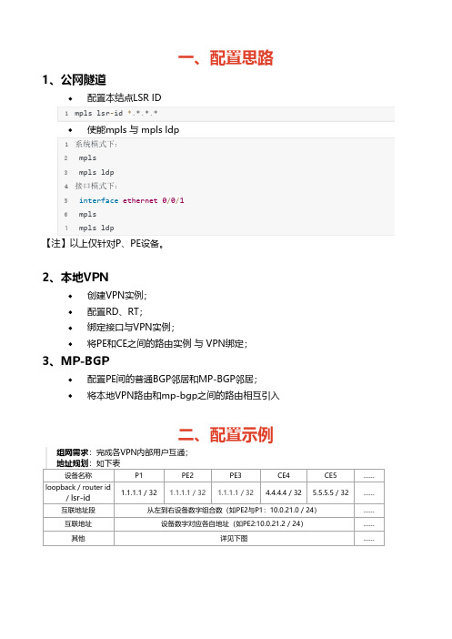
一、配置思路1、公网隧道配置本结点LSR ID1mpls lsr‐id *.*.*.*使能mpls 与 mpls ldp1系统模式下:2 mpls3 mpls ldp4接口模式下:5 interface ethernet 0/0/16 mpls7 mpls ldp【注】以上仅针对P、PE设备。
2、本地VPN创建VPN实例;配置RD、RT;绑定接口与VPN实例;将PE和CE之间的路由实例 与 VPN绑定;3、MP-BGP配置PE间的普通BGP邻居和MP-BGP邻居;将本地VPN路由和mp-bgp之间的路由相互引入二、配置示例组网需求:完成各VPN内部用户互通;地址规划:如下表设备名称P1PE2PE3CE4CE5……loopback / router id/ lsr-id 1.1.1.1 / 32 1.1.1.1 / 32 1.1.1.1 / 32 4.4.4.4 / 32 5.5.5.5 / 32……互联地址段从左到右设备数字组合数(如PE2与P1:10.0.21.0 / 24)……互联地址设备数字对应各自地址(如PE2:10.0.21.2 / 24)……其他详见下图……1、公网隧道配置P与PE的IGP路由(ospf);配置P与PE的LSR ID,并使能系统及接口下的mpls和mpls ldp功能;2、本地VPN创建VPN实例;配置RD、RT;1ip vpn‐instance company‐12 route‐distinguisher 100:13 vpn‐target 100:1 export‐extcommunity4 vpn‐target 100:1 import‐extcommunity56ip vpn‐instance company‐27 route‐distinguisher 100:28 vpn‐target 100:2 export‐extcommunity9 vpn‐target 100:2 import‐extcommunity10 //PE1与PE2该配置相同绑定私网接口与VPN实例;在PE上, 与对应用户(CE设备)相连接口与VPN进行绑定(CE设备无感知,接口只需普通地址配置);1 //以PE2为例,其他接口及PE相同2interface GigabitEthernet0/0/03 ip binding vpn‐instance company‐24 ip address 10.0.82.2 255.255.255.0将PE和CE之间的路由实例 与 VPN绑定;1 //PE22ospf 11 vpn‐instance company‐13 area 0.0.0.04 network 10.0.42.0 0.0.0.2555 //CE46ospf 117 area 0.0.0.08 network 10.0.42.0 0.0.0.2559 network 10.0.64.0 0.0.0.2553、MP-BGP配置PE间的普通BGP邻居(只能传递普通IPv4路由);1bgp 100 //PE2配置2 peer 3.3.3.3 as‐number 1003 peer 3.3.3.3 connect‐interface LoopBack045bgp 100 //PE3配置6 peer 2.2.2.2 as‐number 1007 peer 2.2.2.2 connect‐interface LoopBack0配置PE间的MP-BGP邻居(能传递BGP mpls VPN的私网路由,即VPNv4路由);建立MP-BGP邻居前提是PE间已经建立了普通的BGP邻居;1BGP 100 //PE2配置2 ipv4‐family vpnv43 peer 3.3.3.3 enable45BGP 100 //PE3配置6 ipv4‐family vpnv47 peer 2.2.2.2 enable配置本地VPN路由和mp-bgp之间的路由相互引入;建立MP-BGP邻居前提是PE间已经建立了普通的BGP邻居;1 bgp 100 //BGP中引入直连和IGP2 ipv4‐family vpn‐instance company‐13 import‐route direct4 import‐route ospf 115 ipv4‐family vpn‐instance company‐225 ip address 10.0.21.1 255.255.255.026 mpls27 mpls ldp28#29interface Ethernet0/0/130 ip address 10.0.13.1 255.255.255.031 mpls32 mpls ldp33#34interface Serial0/0/035 link‐protocol ppp36#37interface Serial0/0/138 link‐protocol ppp39#40interface Serial0/0/241 link‐protocol ppp42#43interface Serial0/0/344 link‐protocol ppp45#46interface GigabitEthernet0/0/047#48interface GigabitEthernet0/0/149#50interface GigabitEthernet0/0/251#52interface GigabitEthernet0/0/353#54wlan55#56interface NULL057#58interface LoopBack059 ip address 1.1.1.1 255.255.255.255 60#61ospf 162 area 0.0.0.027 accounting‐scheme default28 domain default29 domain default_admin30 local‐user admin password cipher F<Z4DJzy<+jKUGU‐KkpB7bo#31 local‐user admin service‐type http32#33firewall zone Local34 priority 1635#36interface Ethernet0/0/037 ip binding vpn‐instance company‐138 ip address 10.0.42.2 255.255.255.039#40interface Ethernet0/0/141 ip address 10.0.21.2 255.255.255.042 mpls43 mpls ldp44#45interface Serial0/0/046 link‐protocol ppp47#48interface Serial0/0/149 link‐protocol ppp50#51interface Serial0/0/252 link‐protocol ppp53#54interface Serial0/0/355 link‐protocol ppp56#57interface GigabitEthernet0/0/058 ip binding vpn‐instance company‐259 ip address 10.0.82.2 255.255.255.060#61interface GigabitEthernet0/0/162#63interface GigabitEthernet0/0/264#65interface GigabitEthernet0/0/366#67wlan68#69interface NULL070#71interface LoopBack072 ip address 2.2.2.2 255.255.255.25573#74bgp 10075 peer 3.3.3.3 as‐number 10076 peer 3.3.3.3 connect‐interface LoopBack077 #78 ipv4‐family unicast79 undo synchronization80 peer 3.3.3.3 enable81 #82 ipv4‐family vpnv483 policy vpn‐target84 peer 3.3.3.3 enable85 #86 ipv4‐family vpn‐instance company‐187 import‐route direct88 import‐route ospf 1189 #90 ipv4‐family vpn‐instance company‐291 import‐route direct92 import‐route ospf 1293#94ospf 195 area 0.0.0.096 network 10.0.21.0 0.0.0.25597 network 2.2.2.2 0.0.0.098#99ospf 11 vpn‐instance company‐1100 import‐route bgp101 area 0.0.0.0102 network 10.0.42.0 0.0.0.25525 authentication‐scheme default26 authorization‐scheme default27 accounting‐scheme default28 domain default29 domain default_admin30 local‐user admin password cipher F5S!+T‐YL&:z9:%F`[a=vbt#31 local‐user admin service‐type http32#33firewall zone Local34 priority 1635#36interface Ethernet0/0/037 ip address 10.0.13.3 255.255.255.038 mpls39 mpls ldp40#41interface Ethernet0/0/142 ip binding vpn‐instance company‐143 ip address 10.0.35.3 255.255.255.044#45interface Serial0/0/046 link‐protocol ppp47#48interface Serial0/0/149 link‐protocol ppp50#51interface Serial0/0/252 link‐protocol ppp53#54interface Serial0/0/355 link‐protocol ppp56#57interface GigabitEthernet0/0/058 ip binding vpn‐instance company‐259 ip address 10.0.39.3 255.255.255.060#61interface GigabitEthernet0/0/162#63interface GigabitEthernet0/0/264#65interface GigabitEthernet0/0/366#67wlan68#69interface NULL070#71interface LoopBack072 ip address 3.3.3.3 255.255.255.25573#74bgp 10075 peer 2.2.2.2 as‐number 10076 peer 2.2.2.2 connect‐interface LoopBack077 #78 ipv4‐family unicast79 undo synchronization80 peer 2.2.2.2 enable81 #82 ipv4‐family vpnv483 policy vpn‐target84 peer 2.2.2.2 enable85 #86 ipv4‐family vpn‐instance company‐187 import‐route direct88 import‐route ospf 1389 #90 ipv4‐family vpn‐instance company‐291 import‐route direct92 import‐route ospf 1493#94ospf 195 area 0.0.0.096 network 10.0.13.0 0.0.0.25597 network 3.3.3.3 0.0.0.098#99ospf 13 vpn‐instance company‐15 authentication‐scheme default6 authorization‐scheme default7 accounting‐scheme default8 domain default9 domain default_admin10 local‐user admin password cipher a9uRU{EO!7ECB7Ie7'/)Gbd#11 local‐user admin service‐type http12#13firewall zone Local14 priority 1615#16interface Ethernet0/0/017 ip address 10.0.35.5 255.255.255.018#19interface Ethernet0/0/120 ip address 10.0.57.5 255.255.255.021#22interface Serial0/0/023 link‐protocol ppp24#25interface Serial0/0/126 link‐protocol ppp27#28interface Serial0/0/229 link‐protocol ppp30#31interface Serial0/0/332 link‐protocol ppp33#34interface GigabitEthernet0/0/035#36interface GigabitEthernet0/0/137#38interface GigabitEthernet0/0/239#40interface GigabitEthernet0/0/32sysname Huawei3#4aaa5 authentication‐scheme default6 authorization‐scheme default7 accounting‐scheme default8 domain default9 domain default_admin10 local‐user admin password cipher {07;SSP`4Kpe}@HMNPn@fba#11 local‐user admin service‐type http12#13firewall zone Local14 priority 1615#16interface Ethernet0/0/017 ip address 10.0.39.9 255.255.255.018#19interface Ethernet0/0/120 ip address 10.0.90.9 255.255.255.021#22interface Serial0/0/023 link‐protocol ppp24#25interface Serial0/0/126 link‐protocol ppp27#28interface Serial0/0/229 link‐protocol ppp30#31interface Serial0/0/332 link‐protocol ppp33#34interface GigabitEthernet0/0/035#36interface GigabitEthernet0/0/137#38interface GigabitEthernet0/0/240interface GigabitEthernet0/0/341#42wlan43#44interface NULL045#46ospf 1447 area 0.0.0.048 network 10.0.39.0 0.0.0.25549 network 10.0.90.0 0.0.0.25550#51user‐interface con 052user‐interface vty 0 453user‐interface vty 16 2054#55return~ END ~。
华为MPLSVPN基础知识模型PE路由器VRFRD及RT等等
MPLSVPN基础知识:模型、PE路由器、VRF、RD及RT等等2013-07-12 10:07:34红茶三杯vinsoney版权所有,转载请注明出处一、MPLS VPN模型1. PEProvider edge运营商边界设备运营商边界设备,与客户边界设备相连接;运行MPLS;同时在PE上,使用VRF对VPN客户进行隔离;2. PProvider运营商设备运营商设备不直接与客户设备相连接;运行MPLS;P设备往往并不知道VPN客户网络、以及客户的路由;它只负责在Backbone内运载标签数据;3. CEcustomer edge 客户边界设备客户网络中,与PE直连的设备,主要的功能是将VPN客户的路由通告给PE,以及从PE学习同一个VPN下其他站点的路由二、VRFMPLS VPN一个非常吸引人的地方,就是可以让不同客户的路由及数据穿越运营商的MPLS VPN Backbone,而且这些路由和数据又是相互隔离和独立的,即使不同的客户,拥有相同的IPv4地址空间也不要紧;那么作为这些客户路由进入MPLS Backbone入口的设备 -- PE,就显得非常重要了;在PE上有个非常重要的概念—VRF严格的说,VRF的作用现在已经扩展了,我们这里重点讨论在MPLS VPN PE中的运用;VRF:Virtual Routing and Forwarding,翻译成虚拟路由及转发,它是一种VPN路由和转发实例;一台PE路由器,由于可能同时连接了多个VPN用户,这些用户的路由彼此之间需要相互隔离,那么这时候就用到了VRF,PE路由器上每一个VPN都有一个VRF;PE路由器除了维护全局IP路由表之外,还为每个VRF维护一张独立的IP路由表,这张路由表称为VRF路由表;要注意的是全局IP路由表,以及VRF路由表都是相互独立或者说相互隔离的;因为每一个VPN都有一张独立的VRF路由表,所以PE路由器上每一个VPN也会有一张独立的CEF表来转发这些报文,这就是VRF CEF表;一旦在PE路由器上创建了一个VRF,我们就可以将特定的接口物理或逻辑的放入这个VRF,那么这个接口将不再属于全局IP路由表或其他任何VRF,只为该VRF服务;三、RD由于VPN前缀是通过MP-BGP在MPLS VPN网络中扩散,那么可能,同一时间,MPLS VPN网络承载着多个客户的VPN前缀,甚至有可能是相同的IPv4地址空间,那么怎么做到客户之间地址空间的唯一性呢就需要用到RD值了;RD值在VRF中进行配置;RDroute distinguisher64bits,用于在MP-BGP运载VRF前缀时,确保这些前缀的唯一性;但是RD并不会说明该前缀属于哪一个VRF需要搭配RT,RD的功能并不是VPN标示符,因为在一些复杂的VPN环境中,可能一个VPN存在多个RD;RD的最重要的两个功能:与32bits的Ipv4前缀一起构成96bits的VPNv4前缀;如果不同的VPN客户,存在相同的IPv4地址空间,那么可以通过设置不同的RD值从而保证前缀的唯一性;这个64比特的值可以有两种表现形式:AS:nn或者IP-address:nn;其中nn代表数字;最常用的格式是AS:nn,其中AS代表AS号;通常AS是IANA分配给服务提供商的AS号,nn是服务提供商分配给VRF的唯一号码;产生的VPNv4前缀通过MP-BGP在PE路由器之间被传递;四、RTRoute Targets,这玩意就是用来区分customer的;是BGP community 的扩展属性,在VRF中进行配置;它跟在VPNv4前缀后面被一起传递;一条路由可以附加多个RT值;Export RTs通过在vrf中定义export RT值,将使得输出的VPNv4路由携带上该RT值一起传递–以BGP扩展community的方式;注意这些VPNv4路由,是由VPN客户的IPv4路由导入VRF后,加上VRF中配置的RD值所形成的;Import RTsPE会从其他MP-BGP对等体的PE那收到VPNv4的前缀,这些前缀都是携带RT值的;默认情况下,PE是不会将这些VPNv4路由以IPv4的形式装载到VRF路由表里,除非在本地的VRF中,配置import RTs,那么如果import RTs与收到的VPNv4前缀中的RT匹配的话,这些VPNv4前缀才会被以IPv4的形式装载到相应的VRF路由表里,相当于在这里RT起到一个前缀过滤或者识别的作用,这个功能在许多场景中非常有用;VPNv4路由可能携带不止一个RT值,只要有一个匹配import RT即可导入到VRF路由表;五、PE设备逻辑详解PE设备是MPLS VPN部署非常关键的一个环节;上面这张图就是一个典型的PE路由器的逻辑分解图;蓝色的这个框框代表的就是一台PE路由器;我们看到这个PE设备创建了两个VRF,VRF-A对应的是客户A,VRF-B对应的是客户B;一旦创建了两个VRF,我们就可以将特定的接口放入特定的VRF,那么这些接口将只为所属的VRF服务;上图中的PE路由器实际上就有了三张路由表,分别是两张VRF路由表,以及一张全局IP路由表;一个PE路由器连接不同的客户Customer,使用类似虚拟路由器的概念,来进行逻辑上的进行区分,看到上图中的virtual router for A和virtual router for B了么;这些客户甚至有可能使用相同的地址空间,那么我们在一台PE上,使用多个virtual路由表,将客户及客户的路由进行逻辑上的隔离;这里virtual路由表是相对于我们的全局IP路由表的概念;从global接口上学习到的路由,放入全局IP路由表,从VRF接口上学习到的路由,放入相应的VRF路由表;不同的virtual路由表完全隔离;再来看仔细一点,上面这个PE,我们创建了VRF ABC,那么同时一并出现的还有VRF ABC的路由表以及VRF ABC的CEF表;我们将PE上与CE直连的接口放入VRF ABC;接下去来分解一下,看看这里头有什么东西:首先PE上,运行一个Core的IGP协议,这里用的是OSPF 100,这个OSPF进程是为全局IP路由表贡献路由的;OSPF 100与运营商骨干网内的其他设备形成OSPF邻居关系并且交互骨干网Core内的路由,交互这些路由的目的是,可以为后面的MP-BGP的建立服务,因为MP-BGP往往是通过PE之间的Loopback来建,MP-BGP邻居关系建立需要这些IGP 路由;同时后续的LDP也依赖这个Core的IGP协议;接着PE上运行一个MP-BGP,MP-BGP至少有两个address-family也就是地址族,一个是address-family vpnv4,用于和对端的PE交互VPNv4前缀;另一个地址族是address-family ipv4 vrf ABC,注意这个地址族是和vrf ABC关联的,用于获取VPN客户的路由,这个图中就是customer-A;接着PE上跑一个PE-CE的路由协议,例如静态、RIP、EIGRP、BGP等等,目的是为了从VPN客户那,也就是CE设备那学习到VPN客户的路由;注意由于连接CE的接口被放入了VRF ABC,因此通过这个接口学习到的路由,被放入了VRF ABC的路由表;放入了VRF ABC 路由表之后呢接下来就要将路由引入到MP-BGP中,如果PE-CE之间运行的是路由协议是非BGP,那么就需要做路由重发布,将客户路由重发布进address-family ipv4 vrf ABC这个地址族下面,而如果PE-CE之间运行的已经是BGP了,那么路由当然就直接进入MP-BGP了;现在MP-BGP已经有了VPN客户的路由,现在要将这些IPv4的路由前缀,变成VPNv4的路由前缀,通过已经建立起来的VPNv4的邻接关系传递给对端PE;由于这些路由是属于VRF ABC的,而VRF是定义了RD、RT值的,那么这些值在这里就派上用场了;32bits的IPv4路由前缀,搭配上64bits的RD值,就形成了96bits的VPNv4的前缀;另外,RT值跟随着这个VPNV4前缀,被MP-BGP更新给了对端PE;。
华为设备中MPLS_VPN配置实例教材

[RouterB-Serial2/1] quit
(4)
创建从Router A到Router C的静态LSP
# 配置Ingress Router A。 [RouterA] static-lsp ingress AtoC destination 3.3.3.9 32 nexthop 10.1.1.2 out-label 30 # 配置Transit Router B [RouterB] static-lsp transit AtoC incoming-interface serial 2/0 in-label 30 nexthop 20.1.1.2 out-label 50 # 配置Egress Router C。 [RouterC] static-lsp egress AtoC incoming-interface serial 2/0 in-label 50 (5) 创建从Router C到Router A的静态LSP # 配置Ingress Router C。 [RouterC] static-lsp ingress CtoA destination 1.1.1.9 32 nexthop 20.1.1.1 out-label 40 # 配置Transit Router B。 [RouterB] static-lsp transit CtoA incoming-interface serial 2/1 in-label 40 nexthop 10.1.1.1 out-label 70 # 配置Egress Router A。 [RouterA] static-lsp egress CtoA incoming-interface serial 2/0 in-label 70
# 配置完成后,在各路由器上执行display ip routing-table命令,可以看到相互之间都学到了到对方的主机路由。 以Router A为例: [RouterA] display ip routing-table Routing Tables: Public Destinations : 9 Destination/Mask 1.1.1.9/32 2.2.2.9/32 3.3.3.9/32 10.1.1.0/24 10.1.1.1/32 10.1.1.2/32 20.1.1.0/24 127.0.0.0/8 127.0.0.1/32 Routes : 9 NextHop Interface
华为路由器MPLS VPN配置示例
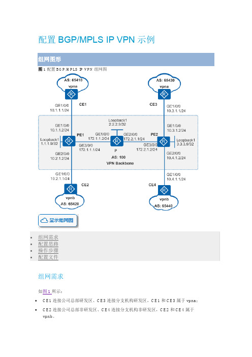
图1 配置BGP/MPLS IP VPN组网图组网需求如图1所示:•CE1连接公司总部研发区、CE3连接分支机构研发区,CE1和CE3属于vpna;•CE2连接公司总部非研发区、CE4连接分支机构非研发区,CE2和CE4属于vpnb。
公司要求通过部署BGP/MPLS IP VPN,实现总部和分支机构的安全互通,同时要求研发区和非研发区间数据隔离。
配置思路采用如下的思路配置BGP/MPLS IP VPN:1.P、PE之间配置OSPF,实现骨干网的IP连通性。
2.PE、P上配置MPLS基本能力和MPLS LDP,建立MPLS LSP公网隧道,传输VPN数据。
3.PE1和PE2上配置VPN实例,其中,vpna使用的VPN-target属性为111:1,vpnb使用的VPN-target属性为222:2,以实现相同VPN间互通,不同VPN间隔离。
同时,与CE相连的接口和相应的VPN实例绑定,以接入VPN用户。
4.PE1和PE2之间配置MP-IBGP,交换VPN路由信息。
5.CE与PE之间配置EBGP,交换VPN路由信息。
操作步骤1.在MPLS骨干网上配置OSPF协议,实现骨干网PE和P的互通# 配置PE1。
<Huawei> system-view[Huawei] sysname PE1[PE1] interface loopback 1[PE1-LoopBack1] ip address 1.1.1.9 32[PE1-LoopBack1] quit[PE1] interface gigabitethernet 3/0/0[PE1-GigabitEthernet3/0/0] ip address 172.1.1.1 24[PE1-GigabitEthernet3/0/0] quit[PE1] ospf 1[PE1-ospf-1] area 0[PE1-ospf-1-area-0.0.0.0] network 172.1.1.0 0.0.0.255[PE1-ospf-1-area-0.0.0.0] network 1.1.1.9 0.0.0.0[PE1-ospf-1-area-0.0.0.0] quit[PE1-ospf-1] quit# 配置P。
MPLS VPN技术原理与配置 华为数通HCIP

各层VPN:数据链路层:PPTP L2F L2TP网络层:Ipsec Gre应用层:SSL DPNVPN技术:虚拟专用网(帧中继、X.25等)定义:是一种逻辑的隔离技术,就好像在两个站点之间跨越公共网络建立了专用的隧道,站点通过隧道实现通信产生原因:能提高带宽利用率,价格相对于专线比较便宜,因此成为构成早期VPN网络的主要技术VPN网络的特点:使用共享的公共网络环境实现各私网的连接不同的私有网络之间相互不可见企业用户接入运营商的网络结构企业用户的网络设备:RTA,RTB,RTF与RTG被称为CE(Customer Edge)设备运营商的网络设备:RTC与RTE,设备直接与客户设备相连,被称为PE(Provider Edge)设备RTD,是运营商网络中的骨干设备,被称为P(Provider)设备CE(Customer Edge):用户网络边缘设备,有接口直接与服务提供商SP(Service Provider)网络相连。
CE可以是SVN 或交换机,也可以是一台主机。
通常情况下,CE“感知”不到VPN的存在,也不需要支持MPLSPE(Provider Edge):服务提供商边缘设备,是服务提供商网络的边缘设备,与CE直接相连。
在MPLS网络中,对VPN的所有处理都发生在PE上P(Provider):服务提供商网络中的骨干设备,不与CE直接相连。
P设备只需要具备基本MPLS转发能力,不维护VPN信息用户设备所在的区域,称为一个站点(Site),站点是指相互之间具备IP连通性的一组IP系统,并且这组IP系统的IP连通性不需通过运营商网络实现VPN模型:1。
Overlay VPNOverlay VPN的特点:客户路由协议总是在客户设备之间交换,而运营商对客户网络结构一无所知典型的协议:二层——帧中继三层——GRE与IPSec应用层——SSL VPNOverlay VPN可以在CE设备上建立隧道,也可以在PE设备上建立隧道:在CE与CE之间建立隧道,并直接传递路由信息,路由协议数据总是在客户设备之间交换,运营商对客户网络结构一无所知:优点:不同的客户地址空间可以重叠,保密性、安全性非常好缺点:本质是一种“静态”VPN,无法反应网络的实时变化。
MPLSVPN组网配置方案
MPLSVPN组网配置方案MPLS(Multiprotocol Label Switching)VPN(Virtual Private Network)是一种基于MPLS技术的VPN解决方案,可以提供高速、安全、可靠的连接,适用于企业组网。
下面是一个MPLSVPN组网配置方案的详细介绍。
概述:MPLS VPN网络连接设备包括PE(Provider Edge)设备和CE (Customer Edge)设备。
PE设备通常由ISP(Internet Service Provider)提供和维护,负责连接不同的VPN。
CE设备则位于企业内部,负责连接终端设备和PE设备。
配置方案:1.确定VPN需求和布局:确定各个分支机构和中心机构之间的VPN连接,包括VPN的数量、VPN之间的通信需求、分支机构之间的通信需求等。
2.配置MPLSVPN核心网络:-配置MPLSVPN路由器,包括路由器的基本配置、接口配置和MPLSVPN路由协议配置(如BGP、OSPF等)。
-配置VPN路由之间的互联,使用BGP或其他路由协议配置VPN路由器之间的互联,确保VPN路由可达。
-配置路由策略,根据需求配置路由策略,以控制数据包的转发路径。
3.配置MPLSVPN网络连接设备:-配置PE设备,包括基本配置、接口配置和VPN配置。
PE设备需根据VPN需求配置相应的VPN实例和VPN接口,以实现不同VPN之间的隔离和互联。
-配置CE设备,包括基本配置、接口配置和VPN配置。
CE设备需连接到PE设备,并配置相应的VPN实例和VPN接口。
4.配置MPLSVPN客户端:-配置终端设备,如PC、服务器和路由器等。
设置设备的基本IP配置和VPN客户端配置,以便与CE设备建立VPN隧道。
-配置VPN客户端软件,如VPN客户端软件,以便连接到MPLSVPN中心网络。
5.测试和验证:- 使用Ping、Traceroute等工具测试VPN连接的可达性和延迟,并确保VPN流量能够正常流动。
- 1、下载文档前请自行甄别文档内容的完整性,平台不提供额外的编辑、内容补充、找答案等附加服务。
- 2、"仅部分预览"的文档,不可在线预览部分如存在完整性等问题,可反馈申请退款(可完整预览的文档不适用该条件!)。
- 3、如文档侵犯您的权益,请联系客服反馈,我们会尽快为您处理(人工客服工作时间:9:00-18:30)。
配置BGP/MPLS IP VPN示例图1配置BGP/MPLS IP VPN组网图•组网需求•配置思路•操作步骤•配置文件组网需求如图1所示:•CE1连接公司总部研发区、CE3连接分支机构研发区,CE1和CE3属于vpna;•CE2连接公司总部非研发区、CE4连接分支机构非研发区,CE2和CE4属于vpnb。
公司要求通过部署BGP/MPLS IP VPN,实现总部和分支机构的安全互通,同时要求研发区和非研发区间数据隔离。
配置思路采用如下的思路配置BGP/MPLS IP VPN:1.P、PE之间配置OSPF,实现骨干网的IP连通性。
2.PE、P上配置MPLS基本能力和MPLS LDP,建立MPLS LSP公网隧道,传输VPN数据。
3.PE1和PE2上配置VPN实例,其中,vpna使用的VPN-target属性为111:1,vpnb使用的VPN-target属性为222:2,以实现相同VPN间互通,不同VPN间隔离。
同时,与CE相连的接口和相应的VPN实例绑定,以接入VPN用户。
4.PE1和PE2之间配置MP-IBGP,交换VPN路由信息。
5.CE与PE之间配置EBGP,交换VPN路由信息。
操作步骤1.在MPLS骨干网上配置OSPF协议,实现骨干网PE和P的互通# 配置PE1。
<Huawei> system-view[Huawei] sysname PE1[PE1] interface loopback 1[PE1-LoopBack1] ip address 1.1.1.9 32[PE1-LoopBack1] quit[PE1] interface gigabitethernet 3/0/0[PE1-GigabitEthernet3/0/0] ip address 172.1.1.1 24[PE1-GigabitEthernet3/0/0] quit[PE1] ospf 1[PE1-ospf-1] area 0[PE1-ospf-1-area-0.0.0.0] network 172.1.1.0 0.0.0.255[PE1-ospf-1-area-0.0.0.0] network 1.1.1.9 0.0.0.0[PE1-ospf-1-area-0.0.0.0] quit[PE1-ospf-1] quit# 配置P。
<Huawei> system-view[Huawei] sysname P[P] interface loopback 1[P-LoopBack1] ip address 2.2.2.9 32[P-LoopBack1] quit[P] interface gigabitethernet 1/0/0[P-GigabitEthernet1/0/0] ip address 172.1.1.2 24[P-GigabitEthernet1/0/0] quit[P] interface gigabitethernet 2/0/0[P-GigabitEthernet2/0/0] ip address 172.2.1.1 24[P-GigabitEthernet2/0/0] quit[P] ospf[P-ospf-1] area 0[P-ospf-1-area-0.0.0.0] network 172.1.1.0 0.0.0.255[P-ospf-1-area-0.0.0.0] network 172.2.1.0 0.0.0.255[P-ospf-1-area-0.0.0.0] network 2.2.2.9 0.0.0.0[P-ospf-1-area-0.0.0.0] quit[P-ospf-1] quit# 配置PE2。
<Huawei> system-view[Huawei] sysname PE2[PE2] interface loopback 1[PE2-LoopBack1] ip address 3.3.3.9 32[PE2-LoopBack1] quit[PE2] interface gigabitethernet 3/0/0[PE2-GigabitEthernet3/0/0] ip address 172.2.1.2 24[PE2-GigabitEthernet3/0/0] quit[PE2] ospf[PE2-ospf-1] area 0[PE2-ospf-1-area-0.0.0.0] network 172.2.1.0 0.0.0.255[PE2-ospf-1-area-0.0.0.0] network 3.3.3.9 0.0.0.0[PE2-ospf-1-area-0.0.0.0] quit[PE2-ospf-1] quit配置完成后,PE1、P、PE2之间应能建立OSPF邻居关系,执行display ospf peer命令可以看到邻居状态为Full。
执行display ip routing-table命令可以看到PE之间学习到对方的Loopback1路由。
以PE1的显示为例:[PE1] display ip routing-tableRoute Flags: R - relay,D - download to fib------------------------------------------------------------------------------Routing Tables: PublicDestinations : 11 Routes : 11Destination/Mask Proto Pre Cost Flags NextHop Interface1.1.1.9/32 Direct 0 0 D 127.0.0.1 LoopBack12.2.2.9/32 OSPF 10 1 D 172.1.1.2GigabitEthernet3/0/03.3.3.9/32 OSPF 10 2 D 172.1.1.2GigabitEthernet3/0/0127.0.0.0/8 Direct 0 0 D 127.0.0.1 InLoopBack0127.0.0.1/32 Direct 0 0 D 127.0.0.1 InLoopBack0 127.255.255.255/32 Direct 0 0 D 127.0.0.1 InLoopBack0 172.1.1.0/24 Direct 0 0 D 172.1.1.1 GigabitEthernet3/0/0172.1.1.1/32 Direct 0 0 D 127.0.0.1 GigabitEthernet3/0/0172.1.1.255/32 Direct 0 0 D 127.0.0.1 GigabitEthernet3/0/0172.2.1.0/24 OSPF 10 2 D 172.1.1.2GigabitEthernet3/0/0255.255.255.255/32 Direct 0 0 D 127.0.0.1 InLoopBack0[PE1] display ospf peerOSPF Process 1 with Router ID 1.1.1.9NeighborsArea 0.0.0.0 interface 172.1.1.1(GigabitEthernet3/0/0)'s neighborsRouter ID: 2.2.2.9 Address: 172.1.1.2State: Full Mode:Nbr is Master Priority: 1DR: 172.1.1.1 BDR: 172.1.1.2 MTU: 0Dead timer due in 37 secRetrans timer interval: 5Neighbor is up for 00:16:21Authentication Sequence: [ 0 ]2.在MPLS骨干网上配置MPLS基本能力和MPLS LDP,建立LDP LSP# 配置PE1。
[PE1] mpls lsr-id 1.1.1.9[PE1] mpls[PE1-mpls] quit[PE1] mpls ldp[PE1-mpls-ldp] quit[PE1] interface gigabitethernet 3/0/0[PE1-GigabitEthernet3/0/0] mpls[PE1-GigabitEthernet3/0/0] mpls ldp[PE1-GigabitEthernet3/0/0] quit# 配置P。
[P] mpls lsr-id 2.2.2.9[P] mpls[P-mpls] quit[P] mpls ldp[P-mpls-ldp] quit[P] interface gigabitethernet 1/0/0[P-GigabitEthernet1/0/0] mpls[P-GigabitEthernet1/0/0] mpls ldp[P-GigabitEthernet1/0/0] quit[P] interface gigabitethernet 2/0/0[P-GigabitEthernet2/0/0] mpls[P-GigabitEthernet2/0/0] mpls ldp[P-GigabitEthernet2/0/0] quit# 配置PE2。
[PE2] mpls lsr-id 3.3.3.9[PE2] mpls[PE2-mpls] quit[PE2] mpls ldp[PE2-mpls-ldp] quit[PE2] interface gigabitethernet 3/0/0[PE2-GigabitEthernet3/0/0] mpls[PE2-GigabitEthernet3/0/0] mpls ldp[PE2-GigabitEthernet3/0/0] quit上述配置完成后,PE1与P、P与PE2之间应能建立LDP会话,执行display mpls ldp session命令可以看到显示结果中Status项为“Operational”。
执行display mpls ldp lsp命令,可以看到LDP LSP的建立情况。
以PE1的显示为例:[PE1] display mpls ldp sessionLDP Session(s) in Public NetworkCodes: LAM(Label Advertisement Mode), SsnAge Unit(DDDD:HH:MM)A '*' before a session means the session is being deleted.------------------------------------------------------------------------------PeerID Status LAM SsnRole SsnAge KASent/Rcv------------------------------------------------------------------------------2.2.2.9:0 Operational DU Active 0000:00:01 6/6------------------------------------------------------------------------------TOTAL: 1 session(s) Found.[PE1] display mpls ldp lspLDP LSP Information-------------------------------------------------------------------------------DestAddress/Mask In/OutLabel UpstreamPeer NextHop OutInterface-------------------------------------------------------------------------------1.1.1.9/32 3/NULL2.2.2.9 127.0.0.1 InLoop0*1.1.1.9/32 Liberal/1024 DS/2.2.2.92.2.2.9/32 NULL/3 - 172.1.1.2 GE3/0/02.2.2.9/32 1024/3 2.2.2.9 172.1.1.2 GE3/0/03.3.3.9/32 NULL/1025 - 172.1.1.2 GE3/0/03.3.3.9/32 1025/1025 2.2.2.9 172.1.1.2 GE3/0/0-------------------------------------------------------------------------------TOTAL: 5 Normal LSP(s) Found.TOTAL: 1 Liberal LSP(s) Found.TOTAL: 0 Frr LSP(s) Found.A '*' before an LSP means the LSP is not establishedA '*' before a Label means the USCB or DSCB is staleA '*' before a UpstreamPeer means the session is staleA '*' before a DS means the session is staleA '*' before a NextHop means the LSP is FRR LSP3.在PE设备上配置VPN实例,将CE接入PE# 配置PE1。
