风华LP铝电解电容规格书
电解规格书

\一、适用范围Adapt Range四、试验方法及要求Tests项目Item试验条件Test Conditions性能要求Requirements浪涌电压Surge Voltage 温度15~35℃,施加1.15倍额定电压,充电30秒,放电5分30秒,共循环1000次At15~35℃,applying the1.15U R1000cycles of30son and330s off,无可见损伤No visible damageΔC/C≤±20%tgδ≤初始规定值Initial specified valueI≤初始规定值Initial specified value耐久性Load Life +105℃额定电压5000小时,恢复16小时进行电压处理后:After applying rated voltage1000hours at105℃andthen resumed16hours and manage voltage.ΔC/C±20%初始测量值以内Initial measured valuetgδ≤200%初始规定值Initial specified valueI≤初始规定值Initial specified value高温贮存Shelf Life +105℃,500小时,恢复16小时后:After storage for500hours at+105℃then resumed16hoursΔC/C±20%初始测量值以内Initial measured valuetgδ≤200%初始规定值Initial specified valueI≤200%初始规定值Initial specified value引出端强度Tension Strength IEC68–2试验Ua:拉力10N,10秒IEC68–2Test UaLoading force10N for10S无可见损伤且标志清晰No visible damage;marking legible.可焊性Solderability IEC68–2试验Ta:焊料槽温度为260±5℃,浸渍深度占整个引出线的90%,浸渍持续时间为2秒。
FENGHUA风华规格书
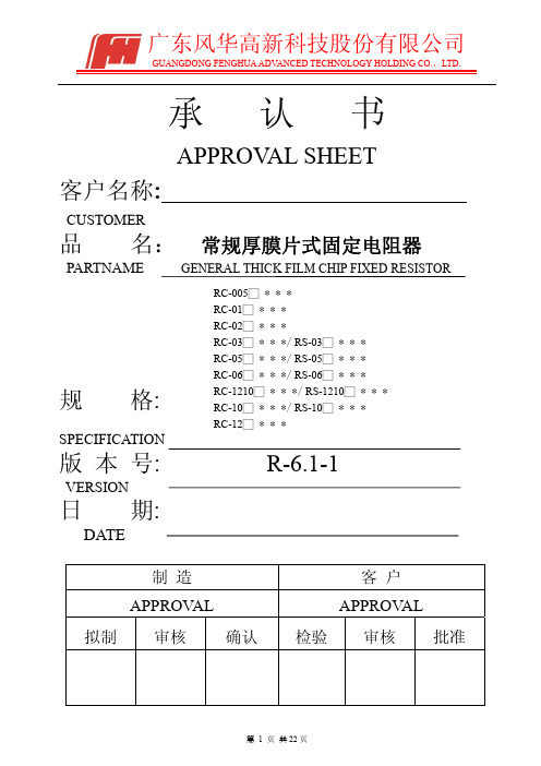
广东风华高新科技股份有限公司GUANGDONG FENGHUA ADV ANCED TECHNOLOGY HOLDING CO.,LTD.承认书APPROV AL SHEET客户名称:CUSTOMER品名:常规厚膜片式固定电阻器PARTNAME规格版本号VERSION日期DATE制造客户APPROV AL APPROV AL 拟制审核确认检验审核批准FENGHUAFENG HUA ADV ANCED TECHNOLOGY (HOLDING) CO., LTD序号 No 目 录TABLE OF CONTENTS1.0 概述Summary2.0 结构及尺寸Structure And Dimensions3.0 型号规格表示办法How To Order4.0 电气性能Performance Specification5.0 可靠性Reliability Data6.0 包装Package7.0 环保情况说明 Environmental Protection Statement 8.0 推荐使用的焊接曲线Recommended soldering profile 9.0 使用注意事项Precautions For UseRC/RS□□□□1.0概述Summary片式电阻器主要生产的型号包括01005、0201、0402、0603、0805、1206、1210、2010、2512。
其特点是:The dimension type for chip resistor including01005、 0201、0402、0603、0805、1206、1210、2010、2512, and the features are as below:*体积小、重量轻miniature and light weight*电性能稳定,可靠性高 stable electrical capability and high reliability *机械强度高、高频特性优越superior mechanical and frequency*装配成本低,并与自动贴装设备匹配low assembly cost, suit for automatic SMT *适应再流焊与波峰焊suit for re-flow and wave flow soldering .*符合ROHS指令要求Compliant with ROHS Directive*符合无卤素要求Compliant with halogen free requirement*禁止使用SS-00259中规定的1级环境管理物质*SONY指定原材料只能从绿色伙伴认定供应商处采购产品广泛应用于计算机、通讯、工业自动化、航天航空、军事、数字电视、数字音响及消费类电子等领域。
铝电解电容器 GRSeries 商品说明书
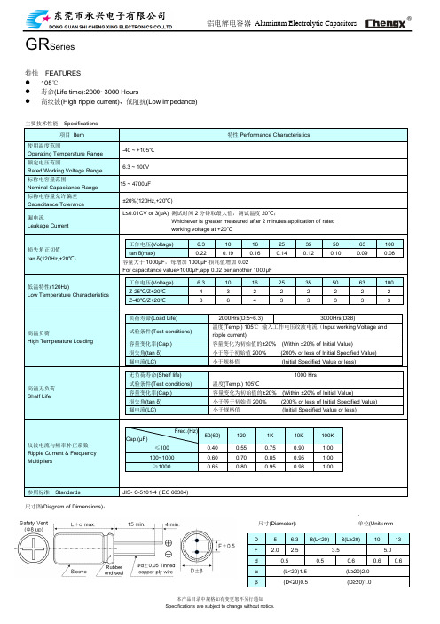
铝电解电容器Aluminum Electrolytic Capacitors GR Series特性FEATURES⚫105℃⚫寿命(Life time):2000~3000 Hours⚫高纹波(High ripple current)、低阻抗(Low Impedance)主要技术性能Specifications项目Item 特性Performance Characteristics使用温度范围Operating Temperature Range-40 ~ +105℃额定电压范围Rated Working Voltage Range6.3 ~ 100V标称电容量范围Nominal Capacitance Range15 ~ 4700μF标称电容量允许偏差Capacitance Tolerance±20%(120Hz,+20℃)漏电流Leakage Current L≤0.01CV or 3(μA) 测试时间2分钟取最大值,测试温度20℃;Whichever is greater measured after 2 minutes application of ratedworking voltage at +20℃损失角正切值tan δ(120Hz,+20℃)工作电压(Voltage) 6.3 10 16 25 35 50 63 100 tan δ(max)0.22 0.19 0.16 0.14 0.12 0.10 0.09 0.08 容量大于1000μF,每增加1000μF损耗值增加0.02For capacitance value>1000μF,app 0.02 per another 1000μF低温特性(120Hz)Low Temperature Characteristics 工作电压(Voltage) 6.3 10 16 25 35 50 63 100 Z-25℃/Z+20℃ 4 3 2 2 2 2 2 2 Z-40℃/Z+20℃8 6 4 3 3 3 3 3高温负荷High Temperature Loading 负荷寿命(Load Life) 2000Hrs(D:5~6.3) 3000Hrs(D≥8)试验条件(Test conditions)温度(Temp.) 105℃输入工作电压纹波电流(Input working Voltage andripple current)容量变化率(Cap.) 容量变化为初始值的±20% (Within ±20% of Initial Value)损失角(tan δ) 小于等于初始值200% (200% or less of Initial Specified Value)漏电流(LC) 小于规格值(Initial Specified Value or less)高温无负荷Shelf Life 无负荷寿命(Shelf life) 1000 Hrs试验条件(Test conditions) 温度(Temp.) 105℃容量变化率(Cap.) 容量变化为初始值的±20% (Within ±20% of Initial Value)损失角(tan δ) 小于等于初始值200% (200% or less of Initial Specified Value) 漏电流(LC) 小于规格值(Initial Specified Value or less)纹波电流与频率补正系数Ripple Current & Frequency MultipliersFreq.(Hz)Cap.(μF)50(60) 120 1K 10K 100K ≤100 0.40 0.55 0.75 0.90 1.00100~1000 0.60 0.70 0.85 0.95 1.00≥1000 0.65 0.80 0.95 0.98 1.00参照标准Standards JIS- C-5101-4 (IEC 60384)尺寸图(Diagram of Dimensions):.尺寸(Diameter): 单位(Unit):mmD 5 6.3 8(L<20) 8(L≥20) 10 13F 2.0 2.5 3.5 5.0d 0.5 0.5 0.6 0.6 0.6α(L<20)1.5 (L≥20)2.0β(D<20)0.5 (D≥20)1.0Voltage(Code) 6.310 16 Cap.(μF) D x L IMP R.C D x L IMP R.C D x L IMP R.C 100 5*11 0.580 140 5*11 0.58 140 6.3*12 0.250 300 120 5*11 0.530 165 5*11 0.53 140 6.3*12 0.250 320150 6.3*12 0.250 185 6.3*12 0.25 340 6.3 *12 0.220 340 8*12 0.150 500180 6.3*12 0.250 255 6.3*12 0.250 340 6.3*12 0.220 340 8*12 0.150 580220 6.3*12 0.250 275 6.3*12 0.220 340 6.3*12 0.220 340 8*12 0.150 600270 6.3*12 0.220 280 6.3*12 0.220 3408*12 0.150 640 8*12 0.130 580330 6.3*12 0.220 340 6.3*12 0.220 3408*12 0.130 640 8*12 0.130 580 8*12 0.130 640390 8*12 0.130 600 8*12 0.130 640 8*12 0.130 640470 8*12 0.130 640 8*12 0.130 6408*12 0.130 640 10*13 0.100 865560 8*12 0.130 640 8*12 0.130 640 10*13 0.100 880680 8*12 0.130 640 8*12 0.130 6408*16 0.087 750 10*13 0.087 8658208*12 0.130 64010*13 0.080 865 10*17 0.075 1210 10*13 0.110 86510008*12 0.130 640 8*16 0.087 76010*17 0.075 1210 10*13 0.087 865 10*17 0.075 121012008*16 0.096 84010*20 0.060 1400 10*20 0.060 1400 10*13 0.087 88015008*20 0.069 105010*20 0.060 1430 10*20 0.060 1430 10*17 0.069 12101800 10*20 0.060 1400 10*20 0.060 1460 10*25 0.052 1650 13*20 0.046 19002200 10*20 0.060 1460 10*20 0.060 1490 13*20 0.045 19202700 10*25 0.050 1650 10*25 0.050 1650 13*25 0.040 2124 13*20 0.050 1650 13*20 0.035 19003300 10*25 0.050 165013*25 0.030 2124 13*20 0.050 18703900 13*20 0.046 19004700 13*25 0.046 2124﹡13mm may be replaced by 12.5mm upon customer’s request.Voltage(Code) 2535 50 Cap.(μF) D x L IMP R.C D x L IMP R.C D x L IMP R.C33 6.3*12 0.500 23039 6.3*12 0.500 26547 6.3*12 0.250 300 6.3*12 0.500 29556 6.3*12 0.250 315 8*12 0.420 51568 6.3*12 0.240 340 8*12 0.420 53582 6.3*12 0.220 320 8*12 0.230 625 8*12 0.420 555100 6.3*12 0.220 340 8*12 0.220 640 10*13 0.200 760120 8*12 0.200 565 8*12 0.200 6558*16 0.200 730 10*13 0.200 780150 8*12 0.180 580 8*12 0.180 670 10*17 0.130 825180 8*12 0.150 600 10*13 0.130 7608*20 0.130 825 10*17 0.130 855220 8*12 0.130 6208*12 0.130 64010*17 0.130 875 8*16 0.100 83010*13 0.100 8302708*12 0.130 64010*17 0.075 1210 10*25 0.093 1025 10*13 0.100 8253308*12 0.130 6658*20 0.087 105013*20 0.090 166010*17 0.075 86510*13 0.100 845 10*17 0.075 1210390 10*13 0.100 865 10*17 0.075 1210 13*20 0.090 16804708*16 0.087 84010*17 0.075 1210 13*25 0.088 1950 10*13 0.100 885560 10*17 0.075 1210 10*20 0.060 1380 13*25 0.088 1970 680 10*17 0.075 1210 10*20 0.058 1400820 10*20 0.060 1370 10*25 0.054 1650 13*20 0.046 19001000 10*20 0.058 1400 13*20 0.046 1920 13*25 0.042 21241200 10*20 0.055 14201500 10*25 0.050 1650 13*20 0.047 19001800 13*25 0.043 21042200 13*25 0.040 2124Voltage(Code) 63100 Cap.(μF) D x L IMP R.C D x L IMP R.C15 6.3*12 1.880 11522 6.3*12 1.050 115 8*12 1.530 23027 6.3*12 1.050 120 8*12 1.320 23233 6.3*12 1.050 125 8*12 1.280 33039 8*12 0.800 200 8*16 0.980 30047 8*12 0.780 212 10*13 0.650 37056 8*12 0.760 222 8*20 0.480 36268 10*13 0.750 234 10*17 0.460 35782 10*13 0.700 314 10*20 0.430 4661008*16 0.630 30010*20 0.430 480 10*13 0.580 314120 10*17 0.324 357 13*20 0.368 530 150 8*20 0.324 362 13*20 0.357 680 180 10*20 0.190 466 13*25 0.328 750 220 10*20 0.190 466 13*25 0.328 880 270 13*20 0.128 670330 13*20 0.128 690390 13*25 0.118 922﹡13mm may be replaced by 12.5mm upon customer’s request.。
风华电容器全系列产品规格书

单位(unit):V
注:头两位数字为有效数字,第三位数字为 0 的个数; R 为小数点。 Note: the first two digits are significant; third digit denotes number of zeros; R=decimal point.
风华高科
广 东 风 华 高 新 科 技 股 份 有 限 公 司
FENGHUA
Fenghua Advanced Technology (Holding) CO. , LTD
※Y5V:The capacitor made of this kind of material is the highest dielectric constant of all ceramic capacitors. They are used over a moderate temperature range in application where high capacitance is required because of its unstable temperature coefficient, but where moderate losses and capacitance changes can be tolerated. Its capacitance and dissipation factors are sensible to measuring conditions, such as temperature and voltage, etc. ※Z5U:The capacitor made of this kind of material is considered as ClassⅡ capacitor, whose temperature characteristic is between that of X7R and Y5V. The capacitance of this kind of capacitor is unstable and sensible to temperature and voltage. Ideally suited for bypassing and decoupling application circuits operating with low DC bias in the environment approaches to room temperature. 二、结构及尺寸
详解铝电解电容器的参数

详解铝电解电容器的参数详解铝电解电容器的参数铝电解电容器的参数详解之一铝电解电容器的基本参数主要有电压、电容量、最高工作温度及寿命、漏电流和损耗因数,有的铝电解电容器,如开关电源输出滤波用的铝电解电容器还有额定纹波电流、ESR等参数。
电压铝电解电容器的电压指标主要有额定DC电压、额定浪涌电压、瞬间过压和反向电压,下面将逐一介绍。
1.反向电压钽电容是有极性电容器,通常不允许工作在反向电压。
在需要的地方,可通过连接一个二极管来防止反极性。
通常,采用导通电压约为0. 8V的二极管是允许的。
在短于Vs的时间内,小于或等于1.5V的反向电压也是可以承受的,但仅仅是短时间,绝不能是连续工作状态。
2.工作电压V OP工作电压是电容器在额定温度范围内所允许的连续工作的电压。
在整个工作温度范围内,电容器既可以在满额定电压(包括叠加的交流电压)下连续工作,也可以连续工作在0V与额定电压之间任何电压值。
在短时间内,电容器也可承受幅值不高于-1. 5V的反向电压。
反向电压的危害主要是反向电压将产生减薄氧化铝膜的电化学过程,从而不可逆地损坏铝电解电容器。
3.额定DC电压VR额定DC电压VR是电容器在额定温度范围内所允许的连续工作电压,它包括在电容器两电极间的直流电压和脉动电压或连续脉冲电压之和。
通常,钽电容的额定电压在电容器表面标明。
通常额定电压≤100V为“低压”铝电解电容器,而额定电压≥150V为“高压”铝电解电容器。
额定电压的标称电压为:3V、4V、6.3V、(7.5V)、10V、16V、25V、35V、(40V)、50V、63V、80V、100V、160V、200V、250V、300V、(315V)、350V、(385V)、400V、450V、500V、(550V)。
其中括号中的电压值为我国不常见的。
4.额定浪涌电压Vs额定浪涌电压Vs是铝电解电容器在短时间内能承受的电压值,其测试条件是:电容器工作在25℃,在不超过30s,两次间隔不小于5min。
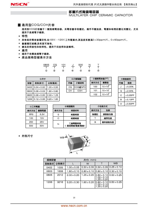
风华通用型COG贴片电容器规格书_nscn
风华直接授权代理/片式无源器件整合供应商 【南京南山】
风华直接授权代理/片式无源器件整合供应商 【南京南山】
风华直接授权代理/片式无源器件整合供应商 【南京南山】
风华直接授权代理/片式无源器件整合供应商 【南京南山】
风华直接授权代理/片式无源器件整合供应商 【南京南山】
风华直接授权代理/片式无源器件整合供应商 【南京南山】
风华直接授权代理/片式无源器件整合供应商 【南京南山】
风华直接授权代理/片式无源器件整合供应商 【南京南山】
风华直接授权代理/片式无源器件整合供应商 【南京南山】
风华直接授权代理/片式无源器件整合供应商 【南京南山】
。
39uf 电解电容规格书
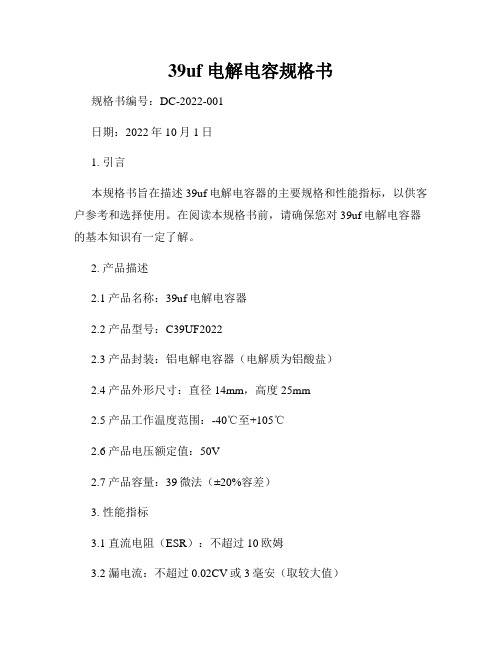
39uf 电解电容规格书规格书编号:DC-2022-001日期:2022年10月1日1. 引言本规格书旨在描述39uf电解电容器的主要规格和性能指标,以供客户参考和选择使用。
在阅读本规格书前,请确保您对39uf电解电容器的基本知识有一定了解。
2. 产品描述2.1 产品名称:39uf 电解电容器2.2 产品型号:C39UF20222.3 产品封装:铝电解电容器(电解质为铝酸盐)2.4 产品外形尺寸:直径14mm,高度25mm2.5 产品工作温度范围:-40℃至+105℃2.6 产品电压额定值:50V2.7 产品容量:39微法(±20%容差)3. 性能指标3.1 直流电阻(ESR):不超过10欧姆3.2 漏电流:不超过0.02CV或3毫安(取较大值)3.3 最大涟漪电流:30毫安有效值3.4 寿命:5000小时(温度为105℃,涟漪电流为最大涟漪电流时)3.5 极性:正极带标记,负极为未标记一端3.6 绝缘电阻:1000兆欧姆或者RC×C(μF),以较小值为准(其中RC为产品额定电压)4. 安装与使用建议4.1 安装电解电容器时,请确保极性正确。
否则,可能会导致电容器损坏或电路故障。
4.2 在使用39uf电解电容器时,请尽量避免超过额定电压和温度范围,以延长产品使用寿命。
4.3 当电容器长时间未使用时,请断开其电源并将其储存于低温、低湿度环境中,以保持其性能和寿命。
5. 产品认证与标准5.1 本产品符合国际电工委员会(IEC)的IEC 60384-1标准要求。
5.2 此外,本产品还通过了ISO 9001质量管理体系认证。
6. 包装与交货6.1 39uf电解电容器将被包装在防静电袋中,以防止静电对产品造成损害。
6.2 产品交货将按照双方协商的时间和地点进行。
7. 售后服务7.1 对于质量问题,请在收到产品后的7个工作日内与我们联系,我们将提供免费的维修或更换服务。
7.2 对于非质量问题的退货和更换,需按照公司规定的退换货流程进行。
风华中高压贴片电容规格书
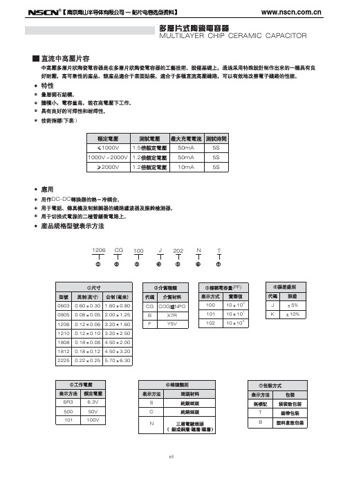
MULTILAYER CHIP CERAMIC CAPACITOR(:)DC Medium-voltage MLCCDC medium-voltage MLCC has good high-voltage reliability,it is made in special design that based on the MLCC technology and equipments.It is suitable for surface-mounting ,can improve the properties of circuits.New monolithic structureThe size of the capacitor is small,yet has high electrostatic capacitance,can operate at high-voltage levels.Has good solderability.Technology Parameter (refer to the picture below):DC-DC converter.The circuit filter and vibration bell of telephone,electrograph and modem.Snubber circuit for switching power supply.FeaturesApplicationsProduct Part Number Expression1206CG100J202NTWMULTILAYER CHIP CERAMIC CAPACITORCapacitance RangeOutside DimensionWMULTILAYER CHIP CERAMIC CAPACITORMULTILAYER CHIP CERAMIC CAPACITORMULTILAYER CHIP CERAMIC CAPACITOR【 南京南山半导体有限公司 — 贴片电容选型资料】MULTILAYER CHIP CERAMIC CAPACITORX7R 1808 (V)10018122225200 200 200 5001000 2000 3000 4000 100 500 1000 2000 3000 4000 100 500 1000 2000 3000 4000 5000 /250 /250 /250100PF 150PF 330PF 470PF 680PF 1000PF 1nF 2.2nF 3.3nF 4.7nF 6.8nF 10nF 12nF 15nF 22nF 27nF 33nF 39nF 47nF 56nF 68nF 100nF 120nF 150nF 220nF 270nF 330nF 470nF 680nF 1 F 2.2 F 3.3 F 10 F 22 F75【 南京南山半导体有限公司 — 贴片电容选型资料】ItemX7R Medium-voltage MLCCDielectric 1808 1812 2225 Size Rated 100 200 5001000 2000 3000 4000 100 200 500 1000 2000 3000 4000 100 200 500 1000 2000 3000 4000 5000 /250 /250 Volatage(V) /250 Capacitance 100PF 150PF 330PF 470PF 680PF 1000PF 1nF 2.2nF 3.3nF 4.7nF 6.8nF 10nF 12nF 15nF 22nF 27nF 33nF 39nF 47nF 56nF 68nF 100nF 120nF 150nF 220nF 270nF 330nF 470nF 680nF 1 F 2.2 F 3.3. F 10 F 22 F76【 南京南山半导体有限公司 — 贴片电容选型资料】MULTILAYER CHIP CERAMIC CAPACITORY5V 0603 (V) 100 100 0805 200 250 100 1206 200 250 100 1210 200 250 100 1812 200 250 100 2225 200 2501000PF 1.5nF 2.2nF 3.3nF 4.7nF 6.8nF 10nF 12nF 15nF 22nF 27nF 33nF 39nF 47nF 56nF 68nF 100nF 150nF 220nF 270nF 330nF 390nF 470nF 680nF 820nF 1 F 2.2 3.3 10 F F F77【 南京南山半导体有限公司 — 贴片电容选型资料】ItemY5V Medium-voltage MLCC 1210 100 200 250 100 1812 200 250 100 2225 200 250Dielectric 0603 0508 1206 Size Rated Volatage(V) 100 100 200 250 100 200 250 Capacitance 1000PF 1.5nF 2.2nF 3.3nF 4.7nF 6.8nF 10nF 12nF 15nF 22nF 27nF 33nF 39nF 47nF 56nF 68nF 100nF 150nF 220nF 270nF 330nF 390nF 470nF 680nF 820nF 1 2.2 3.3 10 F F F F78【 南京南山半导体有限公司 — 贴片电容选型资料】MULTILAYER CHIP CERAMIC CAPACITORCOG1-551251. 2. 3. 2 4. , , , , , 105.3 4 :HP4278A 1. 2. 5 (D.F.) 3. HP4284 25 5 :30% 75% 1.0 0.2V C<1000PF,1.0 0.1MHz; C 1000PF,1.0 0.1KHZ :10( :SF2511) >500V6I.R. 500V: , 60 5>1 5 7 >1 2 >1 21000V 1000V 2000V 2000V50mA 50mA 10mA 150+0/-10 60 55S 5S 5S824 2 -55 125 25975235 5 5 2 0.5 150+0/-10 5% 0.5PF, 10 1 D.F. 24 2 265 5 24 2 25 2.5mm/ : 25 2.5mm/ 60 524510I.R.1 2100 170120 2001 179【 南京南山半导体有限公司 — 贴片电容选型资料】Middle and high Voltage COG MLCC reliability test methodNumber 1 Item Operating Temperature Range Appearance -55 Standard 125 Test Method21.Good ceramic body color continuity. 2.The chips have no visual damages and must be very smooth. 3.No exposed innerelectrode, no cracks or holes. 4.The outer electrode should have no cracks, holes, damages or surface oxidation. 5.Outer electrode no prolongation or the prolongation is less than half of that of the termination width. Within the specified dimensions Within the specified toleranceCr 5PF 0.56% -4 5PF Cr 50PF 1.5[(150/Cr)+7] 10 Cr 50PF 0.15%Check by using microscope10.3 4Dimensions Capacitance Dissipation Factor (DF) Insulation ResistanceUsing micrometer or vernier calipers Measuring Equipment:HP4278 capacitance meter,HP4284 capacitance, Measuring Conditions: 1.Measuring Temperature:25 5 .Humidity: 30%~75%. 2.Measuring Voltage:1.0 0.2V. 3.Measuring Frequency:C<1000PF 1.0 0.1MHz C 1000PF 1.0 0.1KHz Measuring Equipment:Insulation resistance meter (such as Sf2511 insulation resistance). Measuring Method:Must measure at rated voltage, and if Ur>500V,then just use 500V,measure the IR within 60 1 seconds. Ur Max. Current Measuring Time 1000V 1000V 2000V 2000V 50mA 50mA 10mA 5S 5S 5S56C<10nF,IR 5 10 C>10nF,IR CR 500S10Withstanding Voltage 7Requirement >1.5Ur >1.2Ur >1.2Ur8Must meet the capacitor Capacitance temperature coefficient Temperature requirements within the Characteristics operating temperature range. Solderability Tin coverage 75% should be of the outer electrode covered by Tin Appearance Cap. Change ratio No defects visible 5% or 0.5PF whichever is bigger Same as original standard Same as original standardFirst, pre-heat: heat treat 60 5 minutes at 150+0/-10 , then set it for 24 2 hours at room temperature. Measure the capacitance at 55~125 or 55~85 , the capacitance change ratio comparing to that of 25 must be within the specified range. Dip the capacitor into ethanol or colophony solution, and then dip it into 235 5 eutectic solder solution for 2 0.5 seconds. Dipping speed: 25 2.5mm/second. First pre-heat: heat treat for 60 5 minutes at 150+0/-10 , then set it for 24 2 hours at room temperature. Then pre-heat the capacitance according to the following chart. Dip the capacitor into 265 5 eutectic solder solution for 10 1 seconds. Then set it for 24 2 hours at room temperature, then measure. Dipping speed: 25 2.5mm/second. Preheat conditions: Stage Temperature Time 1 2 100 170 120 200 1minutes 1minutes9 Resistance to Soldering10DFIR80【 南京南山半导体有限公司 — 贴片电容选型资料】MULTILAYER CHIP CERAMIC CAPACITOR1 10N11 10N,10 1 :1.0mm/ 11.5mm 10 D.F. 12 55Hz10 55Hz 10Hz 2 6 123 420 mmmm3mm mm mm mmmm150+0/-10 14 24 260 524 281【 南京南山半导体有限公司 — 贴片电容选型资料】NumberItem Adhesive Strength of TerminationStandard No removal of the termination or other defect shall occurTest Method Solder the capacitor to the test jig (glass epoxy resin board) shown in Fig.1 using a eutectic solder.Then apply a 10N force inthe direction shown as the arrowhead.The soldering shall be done either with an iron or using the reflow method and shall be conducted with care so that the soldering is uniform and free of defects such as heat shock,etc.11Fig.1 Vibration Resistance10N,10 1s Speed:1.0mm/s Glss epoxy resin board12Appearance No defects or Solder the capacitor to the test jig (glass epoxy resin abnormities board). The capacitor should be subjected to a simple harmonic motion having a total amplitude of 1.5mm, the Capacitance Within the frequency being varied uniformly between the specified approximate limits of 10 and 55Hz, shall be traversed tolerance range (from 10 Hz to 55 Hz then 10 Hz again) in approximately 1 minute.This motion shall be applied for a period of 2 DF Same as hours in each 3 mutually perpendicular directions original (total is 6 hours). standardFig.2 Bending Resistance No cracks or other defects shall occur Solder the capacitor to the test jig (glass epoxy resin board) shown in Fig.3 using a eutectic solder. Then apply a force in the direction shown in Fig.4. The soldering shall be done either with an iron or using the reflow method and shall be conducted with care so that the soldering is uniform and free of defects such as heat shock, etc. mmmm13mmmm mmmmTemperature Cycle 14Appearance No defects or abnormitiesPre-treatment: Heat-treat the capacitor for 60 5 minutes at 150+0/-10 , then set it for 24 2 hours at room temperature. Perform five cycles according to the four heat treatments listed in the following table. Set it for 24 2 hours at room temperature, the measure.82【 南京南山半导体有限公司 — 贴片电容选型资料】MULTILAYER CHIP CERAMIC CAPACITOR2.5% 0.25PF, min. 14 D.F. I.R. 10000M 1 2 3 4 2 3 30 2 30 2 3 3 3 34029095 24 2500+24/-05% 0.5PF, 15 ( ) D.F. I.R. 10000M1.5 50mA ( 5% 0.5PF, 16 .) >2000V100012 24 21.2D.F. I.R. 10000M83【 南京南山半导体有限公司 — 贴片电容选型资料】NumberItems Temperature CycleStandard Cap. Change ratio 2.5% or 0.25PF whichever is larger Same as original standard More than 10000M Heat-treatment:Test MethodD.F. 14 I.R.Stage Temperature Time 1 lowest operating temperature 3 30 2 2 Room Temperature 3 Highes operating temperature 2 30 4 Room Temperature 2min. 3 3 3 3Humidity Steady State 15AppearanceNo defects or abnormities 5% or 0.5PF whichever is larger Same as original standard More than 10000M No defects or abnormities 5% or 0.5PF (whichever is larger) Same as original standard More than 10000MSet the capacitor for 500+24/-0 hours at the condition of 40 2 and 90-95% humidity. Then remove and set it for 24 2 hours at room temperature, then measure.Cap. Change ratioD.F.I.R. Life Test AppearanceCap. Change ratio 16Apply 1.5 times rated voltage to the capacitor for 1000 12 hours at the upper temperature limits, the charging current should be less than 50mA. Remove and set it for 24 2 hours at room temperature, then measure.(If Ur>2000V,apply 1.2times Ur to test)D.F.I.R.84【 南京南山半导体有限公司 — 贴片电容选型资料】MULTILAYER CHIP CERAMIC CAPACITORX7R1-551251. 2. 3. 2 4. , , , , , 105.3 4 : HP4278A HP42845(D.F.)25010-41.255:30% 75% 2. 3. : :1.0 :1.0 0.2V 0.1KHz ( :SF2511 ) >500V , 60 56I.R.C 25nF,IR 10000M C>25nF,R C 500S 500V:>1 5 7 >1 2 >1 21000V 1000V 2000V 2000V50mA 50mA 10mA5S 5S 5S150+0/-10 24 8 25 -55 125 2605235 9 75 245 5 25 2.5mm/ 2 0.5585【 南京南山半导体有限公司 — 贴片电容选型资料】General X7R MLCC reliability test methodNumber 1 Item Operating Temperature Range Appearance -55 Standard 125 Test Method21.Good ceramic body color continuity. 2.The chips have no visualdamages and must be very smooth. 3.No exposed inner- electrode, no cracks or holes. 4.The outer electrode should have no cracks, holes, damages or surface oxidation. 5.Outer electrode no prolongation or the prolongation is less than half of the termination width. Within the specified dimensions Within the specified tolerance 250 10-4Check by using microscope10 .3 4Dimensions Capacitance Dissipation Factor (DF)5Using micrometer or vernier calipers Measuring Equipments: HP4278 capacitance meter, HP4284 capacitance, Measuring Conditions: 1.Measuring Temperature: 25 5 . Humidity: 30% 75%. 2.Measuring Voltage: 1.0 0.2V. 3.Measuring Frequency:1.0 0.1KHz Measuring Equipment: Insulation resistance meter (such as Sf2511 insulation resistance). Measuring Method: Must measure at rated voltage, and measure the IR within 60 1 seconds. Ur 1000V 1000V 2000V Max. Current Measuring Time 50mA 50mA 10mA 5S 5S 5SInsulation Resistance 6C 25nF,IR 10000M C>25nF,R C 500SWithstanding Voltage 7Requirement >1.5Ur >1.2Ur >1.2Ur2000V8Capacitance Temperature CharacteristicsMust meet the capacitor character temperature coefficient requirements within the operating temperature range. 75% of the outer electrode should be covered by TinFirst, pre-heat: heat treat 60 5 minutes at 150+0/-10 ,then set it for 24 2 hours at room temperature. Measure the capacitance at -55 125 ,the capacitance change ratio comparing to that of 25 must be within the specified range. Dip the capacitor into ethanol or colophony solution,and then dip it into 245 5 eutectic solder solution for 2 0.5 seconds. Dipping speed:25 2.5mm/second.Solderability 986【 南京南山半导体有限公司 — 贴片电容选型资料】MULTILAYER CHIP CERAMIC CAPACITOR150+0/-10 10% D.F. 10 I.R. 25 : 10 1 24 2 26560 5 24522.5mm/1 2100 170120 2001 1110N11 10N,10 1 :1.0mm/ 11.5mm 10 D.F. 55Hz 55Hz 10Hz 1 2 12 6 1023 13 ( ) 487【 南京南山半导体有限公司 — 贴片电容选型资料】NumberItemStandardTest Method First pre-heat: heat treat for 60 5 minutes at 150+0/-10 , then set it for 24 2 hours at room temperature. Then pre-heat the capacitance according to the following chart. Dip the capacitor into 265 5 eutectic solder solution for 10 1s. Then set it for 24 2 hours at room temperature, then measure. Dipping speed: 25 2.5mm/second. Preheat conditions: Stage Temperature Time 1 2 100 170 120 200 1minute 1minuteResistance to Appearance No defects visible Soldering Cap. Change Within 10% ratio DF 10 IR Same as original spec. Same as original spec.Adhesive Strength of TerminationNo removal of the terminations or other defect shall occur11Solder the capacitor to the test jig (glass epoxy resin board) shown in Fig.1 using a eutectic solder. Then apply a 10N force in the direction shown as the arrowhead. The soldering shall be done either with an iron or using the reflow method and shall be conducted with care so that the soldering is uniform and free of defects such as heat shock, etc. 10N,10 1s Speed:1.0mm/s Glss epoxy resinboardFig.1 Resistance to Soldering Appearance No defects visible or abnormities Capacitance Within the specified tolerance range D.F. 12 Same as original spec.Solder the capacitor to the test jig (glass epoxy resin board). The capacitor should be subjected to a simple harmonic motion having a total amplitude of 1.5mm, the frequency being varied uniformly between the approximate limits of 10 and 55Hz, shall be traversed (from 10 Hz to 55 Hz then 10 Hz again) in approximately 1 minute. This motion shall be applied for a period of 2 hours in each 3 mutually perpendicular directions (total is 6 hours).Fig.2 Bending Resistance No cracks or other defects shall occur Solder the capacitor to the test jig (glass epoxy resin board) shown in Fig.3 using a eutectic solder. Then apply a force in the direction shown as Fig.4. The soldering shall be done either with an iron or using the reflow method and shall be conducted with care so that the soldering is uniform and free of defects such as heat shock, etc.1388【 南京南山半导体有限公司 — 贴片电容选型资料】MULTILAYER CHIP CERAMIC CAPACITOR20 mmmmmm13mmmmmmmmmin. 20% 1 2 14 D.F. I.R. 3 4 2 3 30 2 30 2 3 3 3 340 20% 15 ( ) D.F. I.R.29095 48 2500+24/-01.5 20% .) 16 D.F. I.R 50mA ( >2000V100012 24 21.289【 南京南山半导体有限公司 — 贴片电容选型资料】NumberItem Bending ResistanceStandardTest Methodmmmmmm13mm mmmmTemperature CycleAppearanceNo defects or abnormities 20%Cap. Change Within ratio 14Stage Temperature Time min. 1 Min. Operating Temperature 3 30 3 2 Room Temperature 2 3 3 Max. Operating Temperature 2 30 3 4 Room Temperature 2 3D.F.Same as original Specification Same as original Specification No defects or abnormities 20% Set the capacitor for 500+24/-0 hours at the condition of 40 2 and 90-95% humidity. Then remove and set it for 48 2 hours at room temperature, then measure.I.R.Humidity Steady StateAppearanceCap. Change within ratio D.F.15 I.R. Life Test AppearanceSame as original Specification Same as original Specification No defects or abnonrmities 20% Apply 1.5 times rated voltage to the capacitor for 1000 12 hours at the upper temperature limits, the charging current should be less than 50mA. Remove and set it for 24 2 hours at room temperature, then measure.(If Ur>2000V,apply 1.2Ur to test.)Cap. Change within ratio 16 D.F.Same as original specification Same as original specificationI.R.90【 南京南山半导体有限公司 — 贴片电容选型资料】MULTILAYER CHIP CERAMIC CAPACITORY5V1-25~851. 2. 3. 2 4. 5. , , , , ,103 4 : HP4278A 1. 5 (D.F.) 500 10-4HP4284 25 5 75% 0.2V 0.1kHz:30% 2. 3. : :1.0 :1.06I.R.C 25nF,IR 40000M C>25nF,R C 500S( : ,: SF2511 60 5)7>300V >400V >500V100V 200V 250V50mA 50mA 50mA5S 5S 5S150+0/-10 8 24 -25 85 2605 25975235 25 0.52455 25 2.5mm/91【 南京南山半导体有限公司 — 贴片电容选型资料】General Y5V MLCC reliability test methodNumber 1 Item Operating Temperature Range Appearance -25 85 Standard Test Method21.Good ceramic body color continuity. 2.The chips have no visualdamages and must be very smooth. 3.No exposed inner- electrode, no cracks or holes. 4.The outer electrode should have no cracks, holes, damages or surface oxidation. 5.Outer electrode no prolongation or the prolongation is less than half of that of the termination width. Within the specified dimensions Within the specified tolerance 500 10-4Check by using microscope10.3 4Dimensions Capacitance) Dissipation Factor (DF)Using micrometer or vernier calipers Measuring Equipments: HP4278 capacitance meter, HP4284 capacitance, Measuring Conditions: 1.Measuring Temperature: 25 5 . Humidity: 30% 75%. 2.Measuring Voltage: 1.0 0.2V. 3.Measuring Frequency: 1.0 0.1KHz Measuring Equipment: Insulation resistance meter (such as Sf2511 insulation resistance). Measuring Method: Must measure at rated voltage, and measure the IR within 60 5seconds. Ur 1000V 1000V 2000V Max. Current Measuring Time 50mA 50mA 10mA 5S 5S 5S5Insulation Resistance 6C 25nF,IR 40000M C>25nF,R C 500SWithstanding Voltage 7Requirement >1.5Ur >1.2Ur >1.2Ur2000VCapacitance Temperature Characteristics 8Must meet the capacitor temperature coefficient requirements within the operating temperature range.First, pre-heat: heat treat 60 5 minutes at 150+0/-10 , then set it for 24 2 hours at room temperature. Measure the capacitance at 55 125 or 55 85 ,the capacitance change ratio comparing to that of 25 must be within the specified range. Dip the capacitor into ethanol or colophony solution,and then dip it into 235 5 (or 245 5 leadless eutectic solder solution) eutectic solder solution hanging lead for 2 0.5seconds. Dipping speed: 25 2.5mm/second.Solderability 975% of the outer electrode should be covered by Tin92【 南京南山半导体有限公司 — 贴片电容选型资料】MULTILAYER CHIP CERAMIC CAPACITOR150+0/-10 30% D.F. I.R. 10 60 5 24 22655 24 2 25 2.5mm/ :1011 2100 170120 200 11 110N11 10N,10 1 :1.0mm/ 11.5mm D.F. 10 55Hz 12 55Hz 10Hz 1 2 6 1023 ( 13 ) 493【 南京南山半导体有限公司 — 贴片电容选型资料】NumberItemStandardTest Method First pre-heat: heat treat for 60 5 minutes at 150+0/-10 , then set it for 24 2 hours at room temperature. Then pre-heat the capacitance according to the following chart. Dip the capacitor into 265 5 eutectic solder solution for 10 1s. Then set it for 24 2 hours at room temperature, then measure. Dipping speed: 25 2.5mm/second. Preheat conditions: Stage Temperature Time 1 2 100 170 120 200 1minute 1minuteResistance to Appearance No defects visible Soldering Cap. Change Z5U, Y5V: within ratio DF 10 IR30%Same as original spec. Same as original spec.Adhesive Strength of TerminationNo removal of the terminations or other defects shall occur11Solder the capacitor to the test jig (glass epoxy resin board) shown in Fig.1 using a eutectic solder. Then apply a 10N force in the direction shown as the arrowhead. The soldering shall be done either with an iron or using the reflow method and shall be conducted with care so that the soldering is uniform and free of defects such as heat shock, etc. 10N,10 1s Speed:1.0mm/s Glss epoxy resinboardFig.1 Resistance to Soldering Appearance No defects visible or abnormities Capacitance Within the specified tolerance range D.F. 12 Same as original spec.Solder the capacitor to the test jig (glass epoxy resin board). The capacitor should be subjected to a simple harmonic motion having a total amplitude of 1.5mm, the frequency being varied uniformly between the approximate limits of 10 and 55Hz, shall be traversed (from 10 Hz to 55 Hz then 10 Hz again) in approximately 1 minute. This motion shall be applied for a period of 2 hours in each 3 mutually perpendicular directions (total is 6 hours).Fig.2 Bending Resistance No cracks or other defects shall occur Solder the capacitor to the test jig (glass epoxy resin board) shown in Fig.3 using a eutectic solder. Then apply a force in the direction shown as Fig.4. The soldering shall be done either with an iron or using the reflow method and shall be conducted with care so that the soldering is uniform and free of defects such as heat shock, etc.1394【 南京南山半导体有限公司 — 贴片电容选型资料】MULTILAYER CHIP CERAMIC CAPACITOR20 mm mmmm13mm mmmmmm30%min. 1 2 3 4 3 2 30 2 30 2 3 3 3 3D.F. 14 I.R.40 30%29095 48 2500+24/-015()D.F. I.R.30% 16 D.F. I.R 48 21.5 50mA10001295【 南京南山半导体有限公司 — 贴片电容选型资料】NumberItem Bending ResistanceStandardTest Methodmmmm13mmmmmmmmTemperature CycleAppearanceNo defects or abnonrmities 2.5Cap. Change Within ratio 14Stage Temperature Time 30 1 Min. Operating Temperature 3 2 Room Temperature 2 3 Max. Operating Temperature 2 30 4 Room Temperature 2min. 3 3 3 3D.F.Same as original spec. Same as original spec. No defects or abnonrmities Set the capacitor for 500+24/-0 hours at the condition of 40 2 and 90-95% humidity. Then remove and set it for 24 2 hours at room temperature, then measure.I.R.Humidity Steady State 15AppearanceCap. Change within 30% ratio Same as D.F. original spec. I.R. Same as original spec. No defects or abnonrmities 30%Life TestAppearanceCap. Change within ratio 16 D.F.Same as original spec. Same as original spec.Apply 1.5 times rated voltage to the capacitor for 1000 12 hours at the upper temperature limits, the charging current should be less than 50mA. Remove and set it for 24 2 hours at room temperature, then measure.I.R.96。
lp 电解电容

lp 电解电容
LP电解电容是一种电子元件,用于存储电荷和电能。
它是由一对电极(通常是金属箔)以及中间的电解质组成的。
LP电解电容的结构包括外壳、电解质、正极与负极等。
电解质通常是液体或胶体,可以通过化学反应来提供电荷。
正极和负极分别连接到电解电容的两端,当电流流过电解电容时,正极吸收电子,负极释放电子。
这种电流通过电解质中的离子传导,形成了容纳电荷的电场。
LP电解电容的特点包括容量大、电压稳定、频率响应宽、损耗小等。
它广泛应用于电子设备中,如电源滤波、耦合和维持时间常数等。
然而,LP电解电容也有一些缺点,比如体积较大、频率特性不如固体电解电容、寿命较短等。
因此,在选择电容时,需要根据具体应用的要求权衡各种因素。
铝电解电容规格书

0.14 0.14 0.14 0.14 0.14
0.12 0.12 0.12 0.12 0.12
Zmax 100 kHz 20 °C Ω
0.26 0.26 0.16 0.16 0.16 0.08
0.26 0.26 0.26 0.16 0.16 0.08 0.08
Please read Cautions and warnings and Important notes at the end of this document.
5 08/08
SMD capacitors Mounting intructions SMD capacitors Mounting intructions Soldering
B41142A5107M000 B41142A5157M000 B41142A5227M000 B41142A5337M000 B41142A5477M000
B41142A7476M000 B41142A7107M000 B41142A7157M000 B41142A7227M000 B41142A7337M000
H 3
Bottom View 4
C±0.2
KAL1135-N
A±0.2
B±0.2
ød±0.5
0.5 max. E
A±0.2
1
0.3 max.
2
H
3
KAL1132-Y
➀ Case ➁ Terminal base board ➂ Minus pole ➃ Plus pole
Case dimensions d × l (mm)
4
4
4
3
3
瓷介电容_风华高科规格书
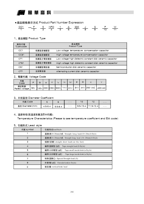
产品规格表示方式Product Part Number Expression1Product Type、产品类型CC11F 253NPO 415A 63307J 8S 9P 102Voltage Code、电压代码代码Code 额定电压Rated VoltageY 400VACF50V G100V A200V K250V L500V N1KV M2KVP3KV Q4KV 3Diameter Coefficient、片径直径代码直径Code Diameter(mm)65.5-6.4…………109.5-10.41211.5-12.4…………4(EIA )、温度特性见温度系数及代码:Temperature Characteristics (Please to see temperature coefficient and EIA code):5Lead style、引线形式代号symbol12345679W 11风华高科X250VAC54.5-5.4产品类型Product Type类型代号Typ e cod eLow voltage temperature compensation capacitor High voltage temperature compensation capacitorLow voltage high dielectric constant disk ceramic capacitor High voltage high dielectric constant disk ceramic capacitor Semiconductor disk ceramic capacitor Alternating current disk ceramic capacitor低压温度补偿型高压温度补偿型低压高介电常数型高压高介电常数型半导体型电容器交流电容器CC1CC81CT1CT81CS1CT7引线形式直脚长式直脚长式()编带直脚型(b式)编带小内弯型(a式)编带大内弯型(a式)特殊直脚S 外单弯(w式)前后翘lead Style(18-28mm)b Straight lon g lead (18~28m )b Style (16-20mm)b Straight long le ad (16~20mm)b Style straight short lead(cut the feet)Tape straight lead (b Style)Tape sm all inside kink (a Style)Tape large inside kink (a Sty le)()Special Straight lead (S)Outside kink(w Style)vertical kink lead短脚切脚6Lead Spacing、脚距7Standard capacitance、标称容量1R04R7100560821102-----注:标称容量以为单位,用位数字表示。
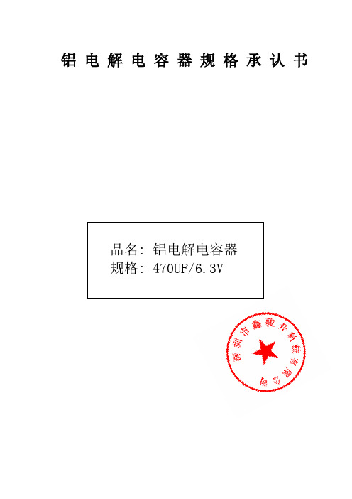
电解电容规格书(带封面)
铝电解电容器规格承认书品名: 铝电解电容器规格: 470UF/6.3V5ALUMINUM ELECTROLYTIC CAPACITORS SPECIFICATION FOR APPOV AL铝电解电容器规格承认书表1:承认项目Type DimensionsTABLE1 RATING&CHARACTERISTIC.CHONG 产品系列表CHONG■NOTE:以上所提供的设计及特性参数谨供参考作用,任何修改不作预先通知.如果在使用上有疑问,请在采购前与我们联络, 以便提供技术上的协助!LEAD FREE TYPE REFLOW SOLDERING CONDITION无 铅 焊 料 产 品 的 回 流 焊 条 件● Recommended Conditions for Reflow Soldering 无铅焊料产品遵循的回流焊条件 (1) Preheat shall be made at 100℃~200℃ and for maximum 180 seconds. 100℃~200℃的预热时间不得超过180秒钟。
(2) Period that temperature at top of capacitor becomes more than 200℃and 230℃shall notexceed t and t1 seconds, respectively.电容器顶部温度高于200℃和230℃的时间,分别不得超过t 和t1所限定的时间。
(3) Temperature at top of capacitor shall not exceed T(℃).在回流焊接时,电容器顶部的最高温度不得超过T (℃)所限定的温度。
● Temperature/Time profile 回流焊温度与时间曲线图● Allowable Range of Peak Temperature 不同壳号的焊接温度及时间● Recommended Land Size 各种壳号的安装尺寸(m m)ALUMINUM ELECTROLYTIC CAPACITORS 'LIFE关于铝电解电容器的寿命T e m p e r a t u r e a t C a p a c i t o r s t o p (℃)Peak temperatureTime (second)Preheat 180sec Maxt sec Maxt1 sec MaxThe life of non-solid aluminum electrolytic capacitors is mainly dependent on environmental conditions (e.g. ambient temperature, humidity etc.) and electrical factors(e.g. operating voltage, ripple current etc.).Generally, the wear-out mechanism of non-solid aluminum electrolytic capacitors is based on evaporation of electrolyte through the rubber seal. Consequently, the factor of temperature (ambient temperature and internal heating due to ripple current) is the most critical to electrolytic capacitor life. The effect of voltage on capacitor life is negligible, especially for low voltage electrolytic capacitors. The lifetime of non-solid aluminum electrolytic capacitors can be expressed as following equations:非固体铝电解电容器的寿命主要依赖于使用环境条件(如环境温度,湿度等)和电负荷情况(如工作电压,纹波电流等)。
电容--电解电容--铝--风华公司--2012--选型表在第4页

承认书APPROV AL SHEET客户:CUSTOMER:品名:PARTNAME:铝电解电容器(E-CAP)系列:SERIES:CD289Y(LY低阻抗值Low impedance) 系列 规格:SPECIFICA TION: 见尺寸表 版本号:VERSION: QWH-17.001 日期:DATE: 2017.11.20 技术部修改记录REVISION RECORDVER 版本MINUTE OF CHANGES更改目录CHECKER检查人RELEASE DATE发行日期序号No 目录INDEX页page1 概述SCOPE 42 订货方式HOW TO ORDER 43 主要特性表MAIN SPECIFICATIONS 54 产品结构PRODUCT STRUCTURE 65 纹波电流频率因子RIPPLE CURRENT FREQUENCY COEFFICIENT8 6 尺寸表、允许纹波电流DIMENSIONS AND RIPPLE CURRENT97 包装PACKING 128 贮存方法STORAGE METHODS 129 其他说明OTHERS 134.1.1内部构造图及构成材料INTERNAL CONSTRUCTION AND COMPONENTS 芯子分解图Dicomposing figure of clement序号组成部分Components材料.规格.处理Materials.Finish/Specification序号组成部分Components材料.规格.处理Materials.Finish/Specification1 铝壳Case铝Aluminum5 隔离物Separator电解纸Paper2 套管Sleeve胶管Sleeve6 正箔Anode foil高纯铝Fine Aluminum3 封口塞SealIIR胶粒IIR rubber7 负箔Cathode foil铝Aluminum4 引线Terminal leadCP线(铁+锡)CP wire (Fe+Sn)8 电解液Electrolyte有机溶剂Organic Solvent etc引出线Terminal leads橡胶塞Seal rubber芯子Element铝壳Case套管Sleeve隔离物Separator 钉花Stitching铝梗Aluminum负箔Cathode foil焊接点Weld引线Terminal leads 正箔Anode foil560(561)12.5×20 12.5×25 0.07 0.034 195012.5×20 12.5×35 16×20 16×25 0.09 0.065 0.065 0.062 1000 2000 1350 135018×350.0362130680(681)10×30 12.5×30 0.045 0.030 1950 2310 16×20 16×25 18×20 0.072 1300 18×35 0.036 1890820(821) 12.5×25 12.5×35 16×20 0.03 0.025 0.035 2300 2570 2570 12.5×35 12.5×40 16×30 0.07 0.055 0.049 1500 1600 1650 18×400.032 2470 1000(102) 16×25 0.025 2555 16×25 16×35 0.05 0.040 1900 1200(122) 16×30 0.022 3010 18×35 0.036 1890 1500(152) 16×35 0.019 3150 18×40 0.032 2470 1800(182) 18×30 0.021 3635 2200(222) 18×35 0.017 3680 18×40 0.038 3860 2700(272) 18×400.0143800(1) 外形尺寸 Case Size D ×L(mm)(2) 100KHz 阻抗值Impedance at 100KHz +20℃ (Ω)(3) 最大允许纹波电流 Max allowable ripple current (mA rms, +105℃,100KHz)6.1客户料号与风华物料对照表 Customer P/N and Fenghua P/N collate list客户P /N 风华P /N-- 8221LEM0812LYN0110--8102LDM1020L YN01108 9 10 11 12 13流传单号码Discriminate mark Sequence numberTaped capacitors are packed into carton, according to the following drawing.22mm L(电容高度)=25±2mmL×W×H(mm)328X235X57Bulk packing capacitors are packed into PVC bag, inner box and carton according to the following drawings.The dimension of the label on the carton is167.5mmX97.5mm贮存方法STORAGE METHODS保存期限:1年,超一年后,需对产品重新加工作电压老练后才使用。
铝电解电容器规格承认书
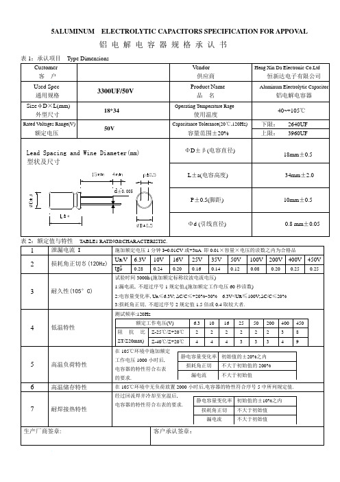
5ALUMINUM ELECTROLYTIC CAPACITORS SPECIFICATION FOR APPOV AL 铝电解电容器规格承认书TABLE1 RATING&CHARACTERISTIC.CONTENTS 产品系列表SERIESNOTE:以上所提供的设计及特性参数谨供参考作用,任何修改不作预先通知.如果在使用上有疑问,请在采购前与我们联络,以便提供技术上的协助!LEAD FREE TYPE REFLOW SOLDERING CONDITION无 铅 焊 料 产 品 的 回 流 焊 条 件● Recommended Conditions for Reflow Soldering 无铅焊料产品遵循的回流焊条件 (1) Preheat shall be made at 100℃~200℃ and for maximum 180 seconds. 100℃~200℃的预热时间不得超过180秒钟。
(2) Period that temperature at top of capacitor becomes more than 200℃and 230℃shall notexceed t and t1 seconds, respectively.电容器顶部温度高于200℃和230℃的时间,分别不得超过t 和t1所限定的时间。
(3) Temperature at top of capacitor shall not exceed T(℃).在回流焊接时,电容器顶部的最高温度不得超过T (℃)所限定的温度。
● Temperature/Time profile 回流焊温度与时间曲线图● Allowable Range of Peak Temperature 不同壳号的焊接温度及时间Size T(℃) t(second) t1(second)φ4~φ6.3 250 90 40 φ8×10.5L 240 90 30 φ10×10.5L2356030● Recommended Land Size 各种壳号的安装尺寸(m m)Size X Y a φ4 1.6 2.6 1.0 φ5 1.6 3.0 1.4 φ6.3 1.6 3.5 2.1 φ8×10.5L 2.5 3.5 3.0 φ10×10.5L2.54.04.0T e m p e r a t u r e a t C a p a c i t o r s t o p (℃)Peak temperatureTime (second)Preheat 180sec Maxt sec Maxt1 sec MaxALUMINUM ELECTROLYTIC CAPACITORS'LIFE关于铝电解电容器的寿命The life of non-solid aluminum electrolytic capacitors is mainly dependent on environmental conditions (e.g. ambient temperature, humidity etc.) and electrical factors(e.g. operating voltage, ripple current etc.).Generally, the wear-out mechanism of non-solid aluminum electrolytic capacitors is based on evaporation of electrolyte through the rubber seal. Consequently, the factor of temperature (ambient temperature and internal heating due to ripple current) is the most critical to electrolytic capacitor life. The effect of voltage on capacitor life is negligible, especially for low voltage electrolytic capacitors. The lifetime of non-solid aluminum electrolytic capacitors can be expressed as following equations:非固体铝电解电容器的寿命主要依赖于使用环境条件(如环境温度,湿度等)和电负荷情况(如工作电压,纹波电流等)。
电解电容器盖板及华司配件(全)

标准插板
规格 20Φ 22Φ 25Φ 30Φ 35Φ
代号 TYJS-AW-01 TYJS-AW-02 TYJS-AW-03 TYJS-AW-04 TYJS-AW-05
D±0.2 18.8 20.8 23.8 28.8 33.8
T±0.2 2.5 3.0
H±0.3 5.6
诚信立业 以质为本 技术创新 满意顾客
宁海县天阳电子有限公司
NIANGHAI TIANYANG ELECTRONIC CO.,LTD
宁海县天阳电子有限公司
NIANGHAI TIANYANG ELECTRONIC CO.,LTD
简
介
Introduction
宁海县天阳电子有限公司成立于1975年,于1997年成立深圳分
·如有特殊要求可另行商定
Note
9
宁海县天阳电子有限公司
NIANGHAI TIANYANG ELECTRONIC CO.,LTD
A. 端 子 盖 板
A08. 四脚端子盖板 CO型
聚脂薄膜
Note
规格 代 号 D±0.2
T±0.2
H±0.3
30Φ TYJS-CO-01 28.8 2.5 3.0 6.8 7.8
公司。是国内规模最大、品种规格最齐全,生产铝电解电容器用端子盖板及 组件的专业厂商。
公司的主要产品有端子盖板、螺栓型盖板(酚醛树脂及聚苯硫醚二大类)、 铝华司、PP和PVC垫片等共千余种规格,广受韩国、巴西、匈牙利、日本与国 内(含港、台地区)各电容器制造商的青睐。同时生产汽车内饰紧固塑料件及 橡胶件。
30Φ TYJS-AO-04 28.8 10.0 12.2
35Φ TYJS-AO-05 33.8 10.0 12.2
- 1、下载文档前请自行甄别文档内容的完整性,平台不提供额外的编辑、内容补充、找答案等附加服务。
- 2、"仅部分预览"的文档,不可在线预览部分如存在完整性等问题,可反馈申请退款(可完整预览的文档不适用该条件!)。
- 3、如文档侵犯您的权益,请联系客服反馈,我们会尽快为您处理(人工客服工作时间:9:00-18:30)。
Code 81 85 8F 8E 11
Lead Foming Type
Bulk 5mm 5mmChip tape ( 4~ 6.3)2.5mm 2.5mmTape ( 4~ 6.3)3.5mm 3.5mmTape ( 4~ 8)5.0mm Lead forming 8)5mm 5mmTape 8mm orininal type(vertical)tape 5mm 5mm Lead forming C Lead forming B B lLead forming ( 4~ 5)2.5mm Lead forming 8x5 F2.5mm ( 4~
4.50
35
50
5.70
6800(682)
25 25 30 25 30 25 30
30 2.80
3.80
4.40
5.10
35
60
6.00
8200(822)
25
25 2.80
35 25 3.30 30 30 30 40 3.50 35 30 30 45 4.00 35 35 40 4.80 35 35 45 5.70 35 40 45 6.30
30 35 30 45 35 45 35 50 40 45 35 50 40 50
2.50
3.20
2700(272)
25
30
2.50
2.90
3.60
3300(332)
25
25
2.40
25 25 30 25 30 25 30 25 30 35 30 35 30 35 35
35 35 30 40 30 45 35 50 40 35 45 35 50 40 50
2.20
(2) 2.10
30 35 30 35 40 35 45 35 45 40 45 35 45
1500(152)
2.40
1800(182)
25 25 30 25 30 30 35 30 35 35
2.70
2200(222)
25
25
2.30
25 25 30 25 30 25 30 25 35 30 35 30 35 35
105 Load life :85 2000 Smaller size 105 2000 hours
Ideally suited for switching power supplies , telecommunication and other electronic products
SPECIFICATIONS
(V) Rated Working voltage
10
16
25 0.45
35 0.40
50
63
80
100
160~250
350~450 0.20
F
Dissipation Factor
tan
0.55 0.50 10000 F When capacitance is o er 10000 tan
(MAX) (20
L F
2.0 1.0 L
L1 2.0
(LP) T CASE SIZE TABLE(
D
30)
T
OD
CASE SIZE TABLE
30 30~60 10.0 35 30~60 10.0 2.0 1.5
L F
241
LP 85 DIMENSIONS, RATED VOLTAGE AND CAPACITANCE
PACKAGING BOXES AND CARTONS DIMENSIONS (mm)
195 335
Brown Green
155
335
325 415 Box Carton
PACKAGING QUANTITY
D 4 5 6.3 8 10
20
12.5
16
18
20
22
L+2max
5-7
5-7
5-11
5-7
11 14-16 5-12
500
14-16
9-12 14-16 20 25-30 16-25
30-55
15-20
21-30 31-40
20
21-30 35-40 41-50
50 10 8 25
25-40 25-35
50 10 25
40
1000 20 15 10 10 8 10
250 500 6 10 6
Code 0405 0505 AA05 0407 0511 AA07 0812 1020 1220 AB27 1320 AD31 1425 AC27 1525 AE40 1725 AF37 1820 2225 A050 A100 F080 B080 B120 C100 G130 D120 E130
Trademark LH NOVA
Code LO LA LB LC LD LE LF LG LJ LH MA MR MG MH MB MY MC MJ MD ME MM MP MQ MN MF MZ VA VB VC VD
Capacitance Range
C<10uF R Decimal point should be expressed by R
ALUMINUM ELECTROLYTIC CAPACITOR
HOW TO ORDER
8
1
1 0 0 L F M 0 5 1 1 W P N 0 8 1 0
2
3
4
5
6
7
8
9
1 0
Type Product Element
Code 8 1
Semifinished Product
2
Voltage 4 6.3 10 16 25 35 50 63 71 80 100 110 120 125 160 180 200 220 250 280 300 310 315 330 350 385 400 450 500 525 c
(tan
)
Shelf Life
+85 (105 ) 1000 After leaving capacitors under no load at +85 listed above
(105
MULTIPLIER FOR RIPPLE CURRENT Frequency coefficient
Freq(Hz) WV(V) 10~100 160~250 350~450 0.88 0.80 0.78 0.90 0.80 0.80 1.00 1.00 1.00 1.10 1.14 1.10 1.15 1.18 1.15 50 60 120 1k 10k
250 10
200 200 100 100 100 8 6 8 6
50 100 10 6
10
4
80 60 40 40 32 20 20 12 10 12 10 8 6.4 4.8 3.2 2.4 2 1.2 1.0 0.8
2 0.5
1 0.5
415X335X335
183
LP
: 85
FEATURES
30 40 4.00 35 30 30 45 4.60 35 35 40 5.20 35 35 45 6.00 35 40 45 6.70 35
-40
~+85
(105
)
-25
~+85
(105
)
1200
F~100000
F 20%(M,+20 ,120Hz)
100uF-2700uF
Leakage Current (tan )
5 I 3 CV ( A) 20 After application of rated voltage for 5 minutes: I 3 CV ( A) at+20 C: ( F) C: Nominal Capacitance in F; V: (V) V: Rated Working Voltage in V
4.40
4.90
5.80
10000(103)
25
30 3.10
5.00
5.40
35
60
6.50
12000(123)
25
25 3.10
25 25 30 25 30 30 35 30 35 35
35 3.50
5.60
6.30
15000(153) 25
25 2.80 25 25 30 25 30
30 3.60 35 3.90 30 40 4.50 30 45 4.80 35 50 40 5.30 35 45 6.10 35 50 6.80 40 45 7.60
Code 0 T A R J F P M C B D 2
Tolerance
Code J K V M Q T A Code same with the series,detailed reference catalague Series WP MS LK Code WP MS LK
C
Cx10
10uF, n
Item Rated Working Voltage Range Operating Temperature Range Nominal Capacitance Range Capacitance Tolerance 10V.DC~100V.DC Performance Characteristics 160V.DC~450V.DC
,120Hz)v
0.35 0.30 0.25 0.20 0.15 1000 F 0.02 shall be added 0.02 with increase of every 1000 10~100 3 12 2000 160~250 4
