RVS贴片铝电解电容85℃系列规格书
VN 85℃无极性Bi-polar
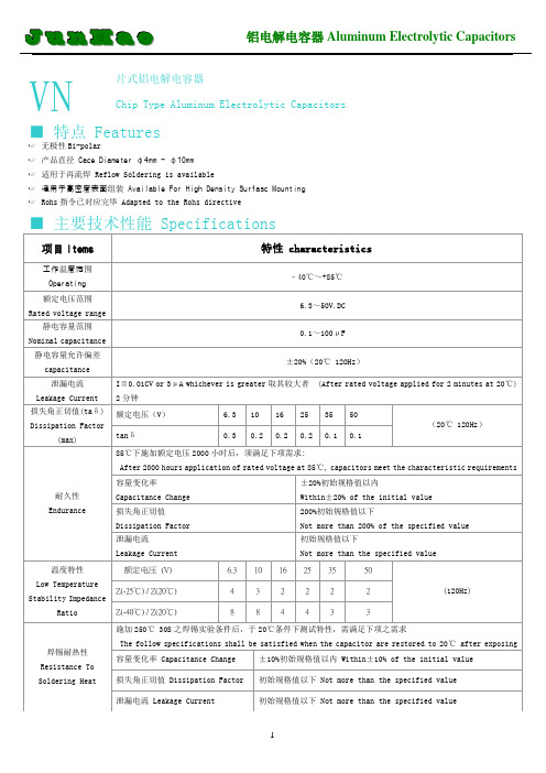
静电容量范围Nominal capacitance range
0.1~100μF
静电容量允许偏差capacitance tolerance
±20%(20℃120Hz)
泄漏电流Leakage Current
I≦0.01CV or 3μA whichever is greater取其较大者(After rated voltage applied for 2 minutes at 20℃) 2分钟
8
8
4
4
3
3
焊锡耐热性Resistance To Soldering Heat
施加250℃30S之焊锡实验条件后,于20℃条件下测试特性,需满足下项之需求
The follow specifications shall be satisfied when the capacitor are restored to 20℃after exposing them at 250℃for 30 seconds
I= Leakage Current (μA) C= Rated Voltage (V)
损失角正切值(taδ)
Dissipation Factor (max)
额定电压(V)
6.3
10
16
25
35
50
(20℃120Hz)
tanδ
0.3
0.2
0.2
初始规格值以下
Not more than the specified value
温度特性Low Temperature Stability Impedance Ratio
额定电压(V)
6.3
10
16
25
无极性贴片铝电解电容CN系列规格书
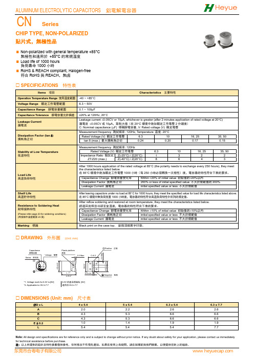
CHIP TYPE, NON-POLARIZED貼片式,無極性品Non-polarized with general temperature +85°C 無極性和適用於 +85°C 的常規溫度 Load life of 1000 hours 負荷壽命1000小時RoHS & REACH compliant, Halogen-free 符合RoHS 與REACH ,無鹵SPECIFICATIONS 特性表Items 項目Characteristics 主要特性Operation Temperature Range 使用温度範圍-40 ~ +85°C Voltage Range 額定工作電壓範圍 6.3 ~ 50V Capacitance Range 靜電容量範圍 0.1 ~ 100μFCapacitance Tolerance 靜電容量允許偏差 ±20% at 120Hz, 20°CLeakage Current 漏電流Leakage current ≤0.05CV or 10μA, whichever is greater (after 2 minutes application of rated voltage at 20°C) 漏電流 ≤0.05CV 或10μA ,取較大值(在20°C 環境中施加額定工作電壓2分鐘後) C: Nominal capacitance (μF) 標稱靜電容量, V: Rated voltage (V) 額定電壓Dissipation Factor (tan δ)損耗角正切Measurement frequency 測試頻率: 120Hz, Temperature 温度: 20°C Rated Voltage (V) 額定工作電壓 6.3 10 16, 25 35, 50 tan δ (max.) 最大損耗角正切 0.24 0.20 0.17 0.15 Stability at Low Temperature低溫特性Measurement frequency 測試頻率: 120HzRated Voltage (V) 額定工作電壓 6.3 10 16, 25 35, 50Impedance Ratio 阻抗比ZT/Z20 (max.) Z(-25°C) / Z(20°C)43 2 2 Z(-40°C) / Z(20°C)8 64 3 Load Life 高溫負荷特性After 1000 hours application of the rated voltage at 85°C (the polarity needs to exchange every 250 hours), they meetthe characteristics listed below.在85°C 環境中施加額定工作電壓1000小時(每250小時必須轉換一次極性)後,電容器的特性符合下表的要求。
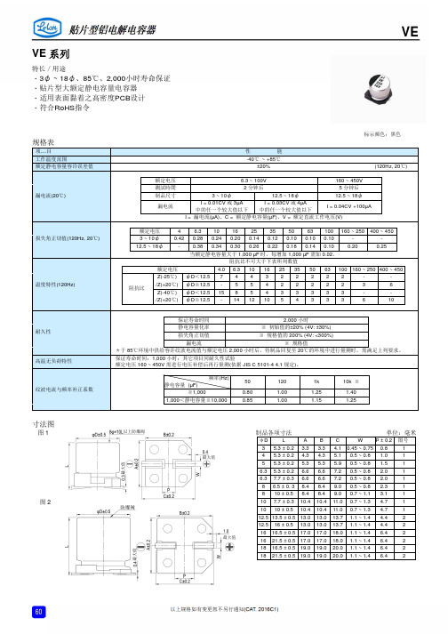
立隆---贴片型铝电 解电容规格书
-
-
12.5 ~ 18φ
- 0.38 0.34 0.30 0.26 0.22 0.18 0.14 0.10 0.20
0.25
当额定静电容量大于 1,000 µF 时,每增加 1,000 µF 需加 0.02。
阻抗比不可大于下表所列数值
额定电压
4.0 6.3 10 16 25 35 50 63 100 160 ~ 250 400 ~ 450
静电容量 (µF)
频率(Hz)
50
≦1,000
0.80
1,000<静电容量≦10,000
0.85
120
1.00 1.00
1k
10k ≦
1.25
1.40
1.15
1.25
寸法图
图1
图2
制品各项寸法
单位:毫米
φD
L
ABC
W P ± 0.2 图号
3 5.3 ± 0.2 3.3 3.3 4.1 0.45 ~ 0.75 0.8
18×16.5 16×21.5
18×21.5
1,450 1,500
1,750
16×16.5
18×16.5 16×21.5
18×21.5
1,100
1,450 1,500
1,750
18×16.5 16×21.5
1,350 1,400
10,000 103
18×21.5 2,000 18×21.5 2,000
124 175 270
6.3×7.7 8×10
124 270
8×10 10×7.7
270 270
8×10 10×10
270 370
10×10
320 12.5×13.5 500
铝电解电容是否符合双85测试
铝电解电容是否符合双85测试的详细解答如下:
首先,铝电解电容在进行双85测试时,通常会符合相关的电气性能和机械性能标准。
双85测试是指将电容在85%的相对湿度和高温(85℃)的条件下进行反复测试,以评估其在高温高湿环境下的性能。
这种测试方法广泛应用于电子产品的可靠性评估。
对于铝电解电容来说,要符合双85测试,需要满足以下几个条件:
1. 耐高温材料:铝电解电容通常需要在高温环境下工作,因此其内部使用的材料必须能够承受高温环境。
一些高品质的铝电解电容会采用耐高温的绝缘材料和电极材料,以延长其使用寿命。
2. 耐电压能力:铝电解电容需要承受较高的直流电压,因此必须具有较高的耐压性能。
高品质的铝电解电容通常采用高分子材料作为电容介质,以提高其耐压性能。
3. 稳定性好:在高温高湿环境下,铝电解电容的电气性能必须保持稳定,不会出现电气参数的变化。
高品质的铝电解电容通常采用先进的生产工艺和质量控制体系,以确保其在各种环境下的稳定性。
经过双85测试的铝电解电容,其性能和寿命可以得到显著提升,从而满足电子产品对可靠性的要求。
然而,需要注意的是,不同品牌和型号的铝电解电容可能存在差异,其性能和寿命也可能会存在一定的差异。
因此,在选择铝电解电容时,需要根据具体应用场景和要求进行选择,以确保产品的可靠性和稳定性。
以上内容仅供参考,建议到相关网站上查询或咨询专业人士。
贴片铝电解电容规格与尺寸
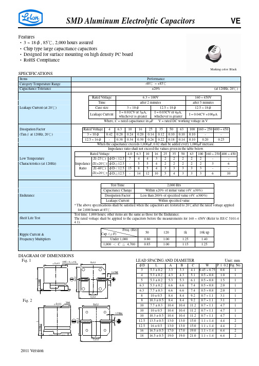
A 3.3 4.3 5.3 6.6 6.6 8.4 8.4 10.4 10.4 10.4 13.0 13.0 17.0 19.0
B 3.3 4.3 5.3 6.6 6.6 8.4 8.4 10.4 10.4 10.4 13.0 13.0 17.0 19.0
P ± 0.2 Fig. No. C W 4.1 0.45 ~ 0.75 0.8 1 5.1 0.5 ~ 0.8 1.0 1 6.1 0.5 ~ 0.8 1.5 1 7.4 0.5 ~ 0.8 2.0 1 7.4 0.5 ~ 0.8 2.0 1 9.2 0.7 ~ 1.1 3.1 1 9.2 0.7 ~ 1.1 3.1 1 11.2 0.7 ~ 1.1 4.7 1 11.2 0.7 ~ 1.1 4.7 1 11.2 0.7 ~ 1.1 4.7 1 15.0 1.1 ~ 1.4 4.4 2 15.0 1.1 ~ 1.4 4.4 2 19.0 1.1 ~ 1.4 6.4 2 21.0 1.1 ~ 1.4 6.4 2
φD×L mA
50V (1H)
φD×L 4×5.3 4×5.3 4×5.3 4×5.3 4×5.3 4×5.3 mA 3 5 6 7 10 14 17 20 35 50 65 75 75 190 190 190
63 (1J)
φD×L 4×5.3 4×5.3 4×5.3 4×5.3 4×5.3 4×5.3 5×5.3 5×5.3 6.3×5.3 8×10 8×10 10×10 10×10 10×10 mA 2 3 4 5 8 12 22 25 40 139 139 200 226 226
ห้องสมุดไป่ตู้
0R1 R22 R33 R47 010 2R2 3R3 4R7 100 220 330 470 680 101 151 221 331 471 681 102 222 332 472 682 V. DC 6.3×5.3 6.3×7.7 6.3×7.7 8×10 89 124 124 290 6.3×5.3 6.3×7.7 6.3×7.7 8×10 10×7.7 10×10 12.5×13.5 12.5×16 16×16.5 18×16.5 89 124 124 290 290 430 890 1,000 1,400 1,700 6.3×7.7 8×10 8×10 10×7.7 10×10 10×10 10×10 12.5×13.5 16×16.5 16×16.5 18×16.5 124 270 290 290 400 410 430 890 1,300 1,400 1,700 6.3×7.7 8×10 8×10 10×7.7 10×10 10×10 12.5×13.5 16×16.5 16×16.5 18×16.5 124 270 290 290 400 410 750 1,100 1,300 1,600 8×10 10×7.7 10×10 10×10 12.5×13.5 12.5×13.5 16×16.5 18×16.5 270 270 400 400 680 750 1100 1,450 3×5.3 4×5.3 4×5.3 5×5.3 5×5.3 6.3×5.3 16 31 34 58 58 89 3×5.3 4×5.3 4×5.3 4×5.3 5×5.3 5×5.3 6.3×5.3 6.3×5.3 16 26 31 34 55 58 89 89 3×5.3 4×5.3 5×5.3 4×5.3 5×5.3 6.3×5.3 5×5.3 6.3×5.3 6.3×5.3 6.3×7.7 14 26 44 31 55 75 58 89 89 109 3×5.3 4×5.3 4×5.3 5×5.3 5×5.3 5×5.3 6.3×5.3 6.3×5.3 6.3×5.3 6.3×7.7 14 26 30 44 55 55 75 89 89 109 3×5.3 4×5.3 5×5.3 5×5.3 6.3×5.3 5×5.3 6.3×5.3 6.3×5.3 6.3×7.7 6.3×7.7 6.3×7.7 14 26 44 47 59 55 67 75 98 109 109 3×5.3 4×5.3 5×5.3 5×5.3 6.3×5.3 6.3×5.3 6.3×7.7 6.3×7.7 6.3×7.7 8×10 10×7.7 8×10 10×10 10×10.3 12.5×13.5 12.5×13.5 16×16.5 18×16.5 14 26 44 47 59 67 85 98 109 252 252 270 370 400 750 680 1,100 1,450
RVT贴片铝电解电容10UF16V4x5规格书

Note: All design and specifications are for reference only and is subject to change without prior notice. If any doubt about safety for your application, please contact us immediately for technical assistance before purchase.注: 以上所提供的設計及特性參數僅供參考,任何修改不作預先通知。
如果在使用上有疑問,請在採購前與我們聯繫,以便提供技術上的協助。
WIDE TEMPERATURE 寬溫品Operating with wide temperature range -40~+105°C 適用於 -40~+105°C 的寬溫範圍 Load life of 1000~2000 hours 負荷壽命1000~2000小時Comply with the RoHS directive 符合RoHS 指令SPECIFICATIONS 特性表Items 項目Characteristics 主要特性Operation Temperature Range 使用温度範圍 -40 ~ +105°C Voltage Range 額定工作電壓範圍 4 ~ 450V Capacitance Range 靜電容量範圍 0.1 ~ 6800μF Capacitance Tolerance 靜電容量允許偏差±20% at 120Hz, 20°C Leakage Current 漏電流Rated Voltage 額定工作電壓 6.3 ~ 100V160 ~ 450VCase size 尺寸 ∅4~∅10∅12.5~∅16∅6.3~∅16Time 時間after 2 min. (application of rated voltage)2分鐘後(施加額定工作電壓)after 1 min. (application of rated voltage) 1分鐘後(施加額定工作電壓) after 5 min. (application of rated voltage)5分鐘後(施加額定工作電壓)Leakage current 漏電流≤0.01CV or 3μA, whichever is greater ≤0.01CV 或3μA ,取較大值≤0.03CV or 4μA, whichever is greater ≤0.03CV 或4μA ,取較大值≤0.04CV+100μA, whichever is greater ≤0.04CV+100μA ,取較大值Dissipation Factor (tan δ) 損耗角正切Measurement frequency 測試頻率: 120Hz, Temperature 温度: 20°C Rated Voltage (V) 額定工作電壓 4 6.31016253550 63 100 160~250350~450tan δ (max.) 最大損耗角正切 ∅4~∅100.420.300.260.220.160.14 0.12 0.10 0.100.20 0.25 ∅12.5~∅160.450.380.340.300.260.22 0.18 0.14 0.100.20 0.25Stability at Low Temperature低溫特性Measurement frequency 測試頻率: 120HzRated Voltage (V) 額定工作電壓 4 6.3101625 35 50~63 100160~250350~450Impedance Ratio 阻抗比ZT/Z20 (max.) ∅4~∅10Z(-25°C)/Z(20°C)7 4 3 2 2 2 2 3 2 3Z(-40°C)/Z(20°C)158 6 4 4 3 3 4 3 6∅12.5~∅16Z(-25°C)/Z(20°C)7 5 4 3 2 2 2 2 2 4Z(-40°C)/Z(20°C)1712108 5 4 3 3 6 10 Load Life 高溫負荷特性After 2000 hrs. (1000 hrs. for ∅4~∅6.3×5.4) application of the rated voltage at 105°C, they meet the characteristics listedbelow. 在105°C 環境中施加額定工作電壓2000小時(∅4~∅6.3×5.4為1000小時)後,電容器的特性符合下表的要求。
铝电解电容 说明书

+ 铝电解电容应用指南 2005.02这个应用指南这个应用指南是铝电解电容的完全手册,当然重点是CDE的型号。
它从结构上深入的揭示了世界上主要的铝电解电容型号的性能和应用的最新信息。
希望你能告诉我们更多你所想知道的,使我们能够完善这本手册。
铝电解电容总论除了一些表面安装技术(SMT)的铝电解电容有固态的电解液之外,一般的电解电容都有一个卷绕电容元件,然后注入电解液,连上端子,密封装入一个罐里。
这个卷绕电容元件包含了一个阳极金属箔,浸透在电解液中的纸隔离物和阴极金属箔。
这个金属箔是高纯度的铝,它的表面用蚀刻技术蚀刻了几十亿的细微管道以增加与电解液的接触面积。
看起来电容量是在两个金属箔之间,实际上是在阳极金属箔和电解液之间。
正极板是阳极金属箔;电介质是阳极金属箔上的绝缘铝氧化物;真正的负极板是导电的液态电解质,阴极金属箔仅仅是连接电解液。
这个结构能产生巨大的电容量,因为蚀刻金属箔可以增加100倍以上的表面积并且铝氧化物的电解质的厚度不超过1微米。
这样的电容器有很大的金属盘面积并且金属盘非常靠近。
这些电容器一般提供0.1UF---3UF的电容值,额定电压从5V---500V。
他们是有极性的器件,有明显的正负极端子,并且有非常多的各种各样的类型,包括浇铸和罐型的SMT的器件,轴向和经向引线罐型,牛角端子型和大罐,螺栓端子型。
最典型的电容电压值是330UF/100V 和6800UF/10V SMT器件100UF/450V,6800UF/50V,10000UF/10V 微型罐型1200UF/450V 和 39000UF/50V 牛角罐型9000UF/450V和390000UF/50V 大罐,螺栓端子型如果两个相同容量的铝电解电容串联,背靠背连接正极端子和负极端子,结果是一个有一半电容值的无极性电容。
两个电容调整所承担的电压,其作用相当于被二极管旁路过来的电压。
当加上电压,极性正确的电容器承担全压。
在无极性的铝电解电容和马达启动铝电解电容里一个第二阳极金属箔替代阴极金属箔,结果在一个壳里里得到一个无极性的电容器。
贴片铝电解电容承认书1

红太洋实业(深圳)有限公司Rubysun Industrial Technology Co., Ltd.承认书客户名称﹕产品类别:贴片铝电解电容产品名称:产品编码:工作温度:-40℃~105℃额定电压:容量范围:使用寿命:2000~5000H主办工程:核准审核制作发行日期客戶承认栏APPROVAL COLUMN产品规格书Product Specification一、概述 SCOPE本产品规格书适用于红太洋实业(深圳)有限公司VT型片式铝电解电容器产品。
The product specification is adapted to series VT V-CHIP Aluminum Electrolytic Capacitors of Rubysun Industrial Technology Co., Ltd..二、外形图及尺寸表 Case size table单位:mm项目 Items 特性 Characteristics工作温度范围Operating TemperatureRange-40℃ ~ 105℃额定电压范围Rated Voltage Range 4V ~ 50V标称电容量范围Nominal CapacitanceRange0.1 ~ 8200 µF标称电容量允许偏差NominalCapacitance Tolerance±20%(20℃,120Hz)漏电流Leakage CurrentI≤0.01C R V R or 3(μA),取较大者(施加额定电压2分钟)C R:标称电容量(μF) U R:额定电压(V)I≤0.01C R V R or 3(μA)) Whichever is greater(After 2 minutes’ application of rated voltage C R: Nominal Capacitance(μF) U R: Rated voltages (V)序号No 目录INDEX 备注page1 概述SCOPE2 外形尺寸图及尺寸表Case size table3 技术性能 SPECIFICATIONS4 称电容量、额定电压、额定纹波电流与外形尺寸对应表Nominal capacitance, rated voltage, rated ripple current and case size5 构造图及材料表 Frame drawing and materials6 试验方法及要求 TESTS7 标志 Marking8 片式铝电解电容的编带V- Chip Type Aluminum Electrolytic CapacitorsITEM4 ×5.45 ×5.46.3 ×5.46.3 ×7.76.3 ×10.58 ×10.58 ×12.510 ×10.510 ×12.512 .5×13.512.5 ×16.516 ×16.518 ×16.518 × 21.5A 1.8 2.1 2.4 2.4 2.4 2.9 2.9 3.2 3.2 4.8 4.8 5.8 6.8 6.8B 4.3 5.3 6.6 6.6 6.6 8.3 8.3 10.3 10.3 13 13 17 19 19C 4.3 5.3 6.6 6.6 6.6 8.3 8.3 10.3 10.3 13 13 17 19 19E 1.0 1.3 2.2 2.2 2.2 3.1 3.1 4.5 4.5 4.4 4.4 6.4 6.4 6.4L 5.4 5.4 5.4 7.7 10.5 10.5 12.5 10.5 12.5 13.5 16.5 16.5 16.5 21.5H 0.5~0.8 0.8 ~ 1.1 1.1~1.4四、称电容量、额定电压、额定纹波电流与外形尺寸对应表I~=Rated ripple current (mA) (105℃, 120VT) I~=额定纹波电流(mA)(105℃,120Hz)五、构造图及材料表 Frame drawing and materials六、试验方法及要求 TestsSPEC: 1)△C/C≤15%2) tgδ<规定值七、标志 Marking (见外形图及尺寸表)说明:标识中的“VT”是红太洋实业(深圳)有限公司VT型贴片产品的专属系列标识。
牛角铝电解电容85℃标准品CD293系列规格书

SNAP-IN TERMINAL TYPE, STANDARD導箔型,標準品Standard snap-in terminal series 導箔型標準品系列Voltage range of 6.3~450V 額定工作電壓範圍6.3~450V Comply with the RoHS directive 符合RoHS 指令SPECIFICATIONS 特性表Items 項目Characteristics 主要特性Operation Temperature Range 使用温度範圍 -40 ~ +85°C -25 ~ +85°C Voltage Range 額定工作電壓範圍 6.3 ~ 350V 400 ~ 450V Capacitance Range 靜電容量範圍 82 ~ 100000μF 68 ~ 560μFCapacitance Tolerance 靜電容量允許偏差 ±20% at 120Hz, 20°CLeakage Current 漏電流Leakage current = 3√(cv) µA (after 5 minutes application of rated voltage) 漏電流 = 3√(cv) µA (施加額定工作電壓5分鐘後)Dissipation Factor (tan δ) 損耗角正切When nominal capacitance is over 1000μF, tan δ shall be added 0.01 to the listed value with increase of every 1000μF. 當標稱靜電容量大於1000μF ,其標稱靜電容量每增加1000μF ,損耗角正切增加0.01。
Measurement frequency 測試頻率: 120Hz, Temperature 温度: 20°CRated Voltage (V) 額定工作電壓6.3 10 16, 2535 50, 63 80, 100 160~400450 tan δ(max.) 最大損耗角正切0.45 0.40 0.35 0.30 0.25 0.20 0.15 0.20 Stability at Low Temperature 低溫特性Measurement frequency 測試頻率: 120HzRated Voltage (V)額定工作電壓6.3~1625 35 50, 63 80~100 160~250350~450Impedance Ratio 阻抗比 Z(-25°C) / Z(20°C) 4 33 2 24 8Z(-40°C) / Z(20°C)15 10 8 6 5 — — Load Life 高溫負荷特性After 2000 hours application of the rated voltage at 85°C, they meet the characteristics listed below. 在85°C 環境中施加額定工作電壓2000小時後,電容器的特性符合下表的要求。
贴片铝电解电容高压长寿命CP系列规格书
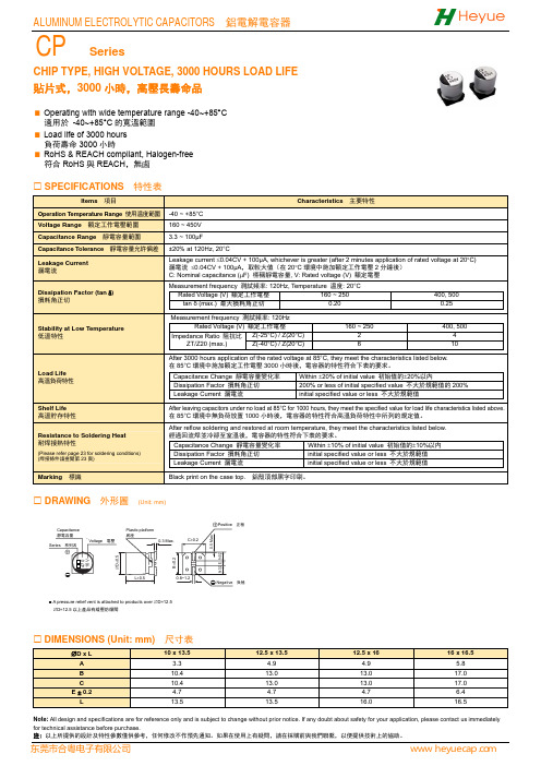
CHIP TYPE, HIGH VOLTAGE, 3000 HOURS LOAD LIFE貼片式,3000小時,高壓長壽命品Operating with wide temperature range -40~+85°C適用於 -40~+85°C的寬溫範圍Load life of 3000 hours負荷壽命3000小時RoHS & REACH compliant, Halogen-free符合RoHS與REACH,無鹵SPECIFICATIONS 特性表Items 項目Characteristics 主要特性Operation Temperature Range 使用温度範圍-40 ~ +85°CVoltage Range 額定工作電壓範圍160 ~ 450VCapacitance Range 靜電容量範圍 3.3 ~ 100μFCapacitance Tolerance 靜電容量允許偏差±20% at 120Hz, 20°CLeakage Current 漏電流Leakage current ≤0.04CV + 100μA, whichever is greater (after 2 minutes application of rated voltage at 20°C) 漏電流 ≤0.04CV + 100μA,取較大值(在20°C環境中施加額定工作電壓2分鐘後)C: Nominal capacitance (μF) 標稱靜電容量, V: Rated voltage (V) 額定電壓Dissipation Factor (tan δ) 損耗角正切Measurement frequency 測試頻率: 120Hz, Temperature 温度: 20°CRated Voltage (V) 額定工作電壓160 ~ 250 400, 500tan δ (max.) 最大損耗角正切 0.20 0.25Stability at Low Temperature 低溫特性Measurement frequency 測試頻率: 120HzRated Voltage (V) 額定工作電壓160 ~ 250400, 500Impedance Ratio 阻抗比ZT/Z20 (max.)Z(-25°C) / Z(20°C) 2 4Z(-40°C) / Z(20°C) 6 10Load Life高溫負荷特性After 3000 hours application of the rated voltage at 85°C, they meet the characteristics listed below.在85°C環境中施加額定工作電壓3000小時後,電容器的特性符合下表的要求。
syk铝贴片电解电容规格书

贴片产品各部位示意图
各规格部位尺寸:
部位代码
4*5.4 5*5.4 6.3*5.4 6.3*7.7 8*10.2 4*5.4A 1.8 2.1 2.4 2.5 2.9 3.2 B 4.3 5.3 6.6 6.6 8.3 10.3 C 4.3 5.3 6.6 6.6 8.3 10.3 E 1.0 1.3 2.2 2.2 3.1 4.5 L 5.4 5.4 5.4 7.7 10.2 10.2 H 0.5—0.8 0.8~1.2 0.8~1.2
Rated ripple current(mA.85℃.120HZ )
纹波电流频率补偿系数
频率
50HZ 120HZ 300HZ 1KHZ
10KHZ 容量范围 0.1—47UF 0.80 1.00 1.20 1.30 1.50
100—1500UF 0.80 1.00 1.10 1.15
1.20
本公司是专业生产.开发和销售SYK 品牌的贴片全系列铝电解电容器的高科技企业,以上是我公司生
产的SYB 系列85℃.,2000H 的产品,以上各种数据会因为规格系列尺寸不同而有所差距,本公司还有SYK,SYZ,SYS,SYC 等各系列产品,同时还可以按照客户的要求设计和生产不同规格和尺寸产品,可月生产不同规格尺寸的贴片电容器2000万只,本公司的产品所用主要原材料都是采购日本.韩国知名铝电解电容器原材料生产商,生产所用机械设备都是目前国际上最先进的机器,保证各品质数据和质量不低于国内同行业生产的产品,保证所有销售产品都是本公司生产工厂原厂产品,严格按照环保要求生产,在产品使用周期内的产品,欢迎各工厂和国内外贸易商来本公司洽谈订货。
贴片铝电解电容规格书丝印说明
贴片铝电解电容规格书丝印说明贴片铝电解电容规格书丝印说明尊敬的用户,非常感谢您选择使用我们的贴片铝电解电容。
为了确保您正确使用并发挥出电容的最佳性能,我们特意为您准备了这篇规格书丝印说明。
请您详细阅读以下内容,并在使用过程中遵循相关指导。
1. 规格说明:- 容量(C):我们的电容提供了多种容量选择,从微型电容到大容量电容,以满足不同应用的需求。
请在选型时仔细考虑您的具体应用场景,确保所选容量符合要求。
- 电压(V):我们提供了不同电压等级的电容。
在使用过程中,请务必确保所选电压等级高于或等于所需工作电压,防止超压损坏电容。
- 允许偏差:由于制造工艺和环境因素的影响,电容的容量和电压可能会存在一定的偏差。
这些偏差通常在规格书丝印上做了标注,请您在使用前了解并合理考虑。
2. 丝印标识:- 容量标识:容量通常以“μF”为单位进行标识,并在丝印上以数字形式显示。
例如,若丝印显示为100,则表示容量为100微法(μF)。
- 电压标识:电容的电压等级通常以“V”为单位进行标识,并在丝印上以数字形式显示。
例如,若丝印上显示为25V,则表示电容的电压等级为25伏特(V)。
- 极性标识:贴片铝电解电容通常为极性电容,正极和负极在表面上会有相应的标记。
请您在使用过程中务必将电容的正极正确连接至正极引脚,负极正确连接至负极引脚。
若连接错误,可能会导致电容损坏或运行异常。
3. 使用注意事项:- 工作温度范围:请确保您的贴片铝电解电容在指定的工作温度范围内使用,避免过高或过低温度对电容造成不可逆的损坏。
- 频率特性:贴片铝电解电容的频率特性可能会受到影响。
在设计电路时,请仔细考虑频率范围,以确保电容在所需频率下表现出稳定的性能。
- 存储条件:若您暂时不使用电容,请将其存放在低温、低湿的环境中,避免长期暴露在高温、高湿的环境下,以防电容受潮和损坏。
总之,通过仔细阅读本规格书丝印说明,并遵循所述的指导,您将能够正确选择和使用我们的贴片铝电解电容。
铝电解规格书

Aluminum Electrolytic Capacitors CS SERIES1.ScopeThis sp ecification covers “CS Series” V-chip aluminum electrolytic capacitors.2.Reference StandardJapanese industrial Standard JIS C-5141 characteristics W and JIS C-5102 except as specified in this specification.3.Environmental Protection StandardComply with the EU directive 2002/95/EC.4.Operating Temperature Range-40︒C ~ +85︒C5.Voltage Range4 ~ 100V6.Capacitance Range0.1~ 1500μF7.Capacitance Tolerance±20% at 120Hz, 20︒C8.Leakage Current1 ≤ 0.01 CV or 3 (μA) whichever is greater (after2 minutes)9.Tan δMeasurement frequency: 120Hz, Temperature: 20︒C10.Stability at Low TemperatureMeasurement frequency: 120Hz11.Load Life12. Shelf LifeAfter leaving capacitors under no load at 85︒C for 1000 hours, they meet the specified value for load life characteristics listed above.13. Resistance to Soldering HeatAfter reflow soldering according to Reflow Soldering Condition (see page 5) and restored at room temperature, they meet the characteristics listed.14. MarkingCapacitors shall be legibly marked with the following: 1) M anufacture’s mark2) R ated voltage and nominal capacitance (6.3 voltage shall be marked with 6 voltage) 3) N egative polarity 4) M arking: Black15. Drawing (Unit: mm)(∅4~∅6.3)(∅8, ∅10) Aluminum Electrolytic Capacitors CS SERIESPlastic platformcsSeries Capacitance Rated V oltage16. Dimensions (Unit: mm)17. Taping SpecificationsApplicable standard JIS C0806(CS, CK, SC, CN, KP, LZ, KZ, FZ, EL, KL, KH, HU series) Carrier Tape17.1. Drawing 1 (for ∅4 ~ ∅10)Dimension17.2. Drawing 2 (for ∅12.5 ~ ∅16)Dimension (Unit: mm)17.3. Reel318. Lead-free Reflow Soldering ConditionA. Recommended Conditions for Reflow Soldering(1)A thermal condition system such as infrared radiation (IR) or hot blast should be adopted, and vapor heattransfer systems (VPS) are not recommended.(2)Reflow soldering should be performed one time. If the capacitor has to be reflowed twice, 30 minutesmust be layout between each time.(3)For lead-free type reflow soldering, please observe proper conditions below:a)The time of preheating from 150°C to 200°C shall be within maximum 180 seconds;b)The time of soldering temperature at 217°C measured on capacitors' top shall not exceed tL (second);c)The peak temperature on capacitors' top shall not exceed Tp(°C), and the time within 5°C of actualpeak temperature shall not exceed tp (second).B. Classification Reflow ProfilePackage quantityTp21720025Temperature温度(︒C)C. Allowable Range of Peak TemperatureD. Recommended Land Size (Unit: mm)19. The Raw Materials of Lead Wire20. Explanation of Part Number1 2 3 4 5 6 7 8 9 10 11 12 13 14 Example: CS 1C 221 M - C R E 77Length (7.7mm) Case Diameter (∅6.3mm) Lead Process (Taping & Reel) Type (Chip) DashCapacitance Tolerance (±20%) Capacitance (220μF) V oltage (16V)Series (CS)SeriesV oltage (WV) Capacitance (μF)Cap. Tol. (%)TypeLead ProcessDia. (∅)Length (mm)21. Construction22. Frequency Coefficient of Allowable Ripple Curren23 Dimensions & Maximum Permissible Ripple CurrentElectrolytic paper Base plateAluminum caseAluminum foil (Anode & cathode foil) Rubber sealLead wireAluminum Electrolytic Capacitors CS SERIESAluminum Electrolytic Capacitors CS SERIESAllowable ripple current (mA rms) at 85℃120Hz24. General Information for ApplicationThe following precautions must be observed when using electrolytic capacitors.A)Circuit Design1)Please make sure that the environmental and mounting conditions to which the capacitor to be exposedare within the conditions specified in this catalogue.2)Operating temperature and applied ripple must be within the specifications.3)Appropriate capacitors, which comply with the life requirement of the products, should be selected whendesigning the circuit.4)Aluminum electrolytic capacitors are polarized. Do not apply reserve voltage or AC voltage. Please usenon-polarized capacitors for a circuit that can possibly see reserved polarity.Note: Non-polarizes capacitors cannot be used for AC voltage application.5)Do not use aluminum electrolytic capacitors in a circuit that requires rapid and very frequent charge ordischarge. In this type of circuit, it is necessary to use special design capacitors with extended life characteristics.6)Do not apply excess voltage.Pleased pay attention so that the peak voltage, which is DC voltage overlapped by ripple current, should not exceed the rated voltage.In the case where more than two aluminum electrolytic capacitors are used in series, please make sure that applied voltage should be lower than rated voltage should be applied to each capacitorequally using a balancing resistor in parallel with the capacitor.7)Outer sleeved of the capacitor is not guarantee as an electrical insulator. Do not use standard sleeve on acapacitor in applications that require electrical insulation. When the application requires special insulation, please contact our sales office for details.8)Capacitors must not be used under following conditions:(a) Capacitors must not be exposed to water (including condensation), brine or oil.(b) Ambient conditions that include toxic gases such as hydrogen sulfide, sulfurous acid, nitrous acid,chlorine, ammonium, etc.(c) Ambient conditions that expose the capacitor to ozone, ultraviolet ray and radiation.Severe vibration and physical shock conditions that exceed our specification.Vibration test condition:Vibration frequency range: 10~55~10HzSweep rate : 10~55~10Hz per minuteSweep method : logarithmicAmplitude or acceleration: 1.5 (max. acceleration is 10G)Direction of vibration : X, Y, Z directionTesting time : 2 hours per each directionShock is not applicable normally.If a particular condition is required, please contact our sales office.9)When designing a circuit board, please pay attention to the following:Make the pad spacing on the PC board matching with the lead space of the capacitor.There should not be any circuit pattern or circuit wire above the capacitor safety vent.10)The main chemical solution of the electrolyte and the separator paper in the capacitor are combustible.The electrolyte is conductive. When it comes in contact with the PC board, there is a possibility of pattern or short circuit between the circuit pattern, which could result in smoking or fire. Do not locate any circuit pattern beneath the capacitor end seal.11)Do not design a circuit board so that heat generating components are placed near an aluminum electrolyticcapacitor or reserve side of PC board (under the capacitor).12)Please refer to the pad size layout recommendations in our catalogue when designing in surface mountcapacitors.13)Electrical characteristics may vary depending on changes in temperature and frequency. Please considerthe variation when you design circuits.14)When you install more than 2 capacitors in parallel, consider the balance of current following in to thecapacitor.B)Mounting1)Once a capacitor has been assembled in the set and power applied, do not attempt to re-use the capacitorin other circuits or application.2)Electric potential between positive and negative terminal may exist as a result of returned electromotiveforce, so please discharge the capacitor using 1KΩ resistor.3)Leakage current of the parts that have stored for long period may increase. When leakage current hasincreased, please perform a voltage treatment using a 1KΩ resistor.4)Please confirm rating and polarity before installing capacitor on the PC board.5)Be careful not to deform the capacitor during installation.6)Please confirm that the lead spacing of the capacitor matches the pad spacing of the PC board prior toinstallation.7)Please pay attention to the mechanical shock to the capacitor by suction nozzle of the automatic insertionmachine or automatic mounted, or by product checker, or by centering mechanism.8)Reflow soldering: please see “Lead –free Reflow Soldering Condition”.9)Do not tilt, lay down or twist the capacitor body after the capacitors are soldered to the PC board.10)Do not carry the PC board by grasping the soldered capacitor.11)Please do not allow anytime to touch the capacitor after soldering. If PC board are stored in stack, pleasemake sure PC board or the other components do not touch the capacitor. The capacitor shall not be effected by any radiated heat from the soldered PC board or other components after soldering.12)CleaningDo not clean capacitors with halogenated cleaning agent. However, if it is necessary to clean withhalogenated cleaning agent, please contact our sales office.Recommended cleaning method: Applicable : Any type, any ratingsCleaning agents : Pine Alpha ST-100S, cleaning through 750H/750L/710M, Sanelek B-12, AquaCleaner 210SEP, Techno Care FRW14~17, Isopropyl Alcohol.Cleaning condition: Total cleaning time shall be within 5 minutes by immersion, ultrasonic or othermethod. Temperature of the cleaning agent shall be 60︒C or lower. Aftercleaning, capacitors should be dried using hot air for minimum of 10 minutesalong with the PC board. Hot air temperature should be below the maximumoperating temperature of the capacitor. Insufficient dry after water rinse maycause appearance problems, sleeve shirk, bottom- plate bulge and such.③ Avoid using ozone destructive substance for cleaning agents to concern about global environment.④ Please consult us regarding other cleaning agents or cleaning methods.C)In The Equipment1) Do not directly touch terminal by hand.2) Do not short between terminal by conductor, nor spill conductible liquid such as alkaline or acidic solutionon or near the capacitor.3) Please make sure that the ambient conditions where the set is installed will be free from spilling water or oil,direct sunlight, ultraviolet rays, radiation, poisonous gases, vibration or mechanical shock.D)Maintenance and InspectionPlease periodically inspect the aluminum capacitors that are installed in industrial equipment. The following Items should be checked:Appearance: Remarkable abnormality such as vent operation, leaking electrolyte etc.Electrical characteristic: Capacitance, dielectric loss tangent, leakage current etc., which are specified in this catalogue.E)In an Emergency1) If you see smoke due to operation of safety vent, turn off the main switch or pull out the plug from theoutlet.2) Do not draw your face to the safety vent since gas over 100︒C will be emitted when the safety vent operates.If the gas has entered your eyes, please flush your eyes immediately in pure water. If you breathed the gas immediately wash out your mouth and throat with water. Do not ingest electrolyte. If your skin is exposed to electrolyte, please wash it away using soap and water.Aluminum Electrolytic CapacitorsF)Storage1)Do not keep capacitor in high temperature and high humidity.Storage conditions should be:Temperature : +5︒C ~ +35︒CHumidity : Lower than 75%Place : Indoor2) Avoid ambient conditions where capacitors can be covered with water, brine or oil.3) Avoid ambient conditions where capacitors are exposed to poisonous gases such as hydrogen sulfide,sulfurous acid, nitrous acid, chlorine, ammonium etc.4) Do not keep capacitor in conditions that expose the capacitor to ozone, ultraviolet ray or radiation.G)DisposalPlease dispose capacitors in either of the following ways:1)Incinerate capacitors after crushing parts or making a hole on the capacitor body.2)Bury capacitors in the ground. Please have a disposal specialist do it.25. NoteAll design and specifications are for reference only and is subject to change without prior notice. If any doubt about safety for your application, please contact us immediately for technical assistance before purchase.11。
贴片电解电容的规格

贴片电解电容的规格→贴片电解电容详细规格书选贴片电容就在东莞荣誉电子。
铝电解电容器的工作介质为通过阳极氧化的方式在铝箔表面生成一层极薄的三氧化二铝(Al2O3),此氧化物介质层和电容器的阳极结合成一个完整的体系,两者相互依存,不能彼此独立;我们通常所说的电容器,其电极和电介质是彼此独立的。
电解电容器的阳极铝箔、阴极铝箔通常均为腐蚀铝箔,实际的表面积远远大于其表观表面积,这也是铝质电解电容器通常具有大的电容量的一个原因。
由于采用具有众多微细蚀孔的铝箔,通常需用液态电解质才能更有效地利用其实际电极面积。
贴片电解电容技术:1 影响大型铝电解电容器耐纹波电流能力的因素通常情况下纹波电流Ir为Ir=(1)式中:α为散热系数;Δt为电容芯包温度与环境温度差(温升);A为电容外表面积。
从式(1)中可知,纹波电流Ir与和成正比。
散热系数α,它包括幅射散热和对流散热,它不仅与产品表面的温度差、直径大小、直立或横卧有关,而且与芯包结构、电容器内的导热情况、热流方向、芯包固定方式等密切相关。
由铝电解电容器等效电路可知tanδ=ωCR(2)式中:R为等效串联电阻,它由三部分所组成,即R=R1+R2+R3(3)式中:R1是氧化膜介质损耗所代表的等效串联电阻;R3是极板、导电层的欧姆电阻以及其间的接触电阻;R2是电解质所代表的等效串联电阻,即R2=φ·ρ·d/2s(4)式中:φ为电解纸的渗透系数;ρ为工作电解液的电阻率(Ω·cm);d为电解纸的厚度(cm);s为阳极箔的外观几何尺寸(cm2)。
由以上分析可知,选用氧化膜介质损耗小的铝箔,选择渗透系数小、厚度薄的电解纸,降低工作电解液的电阻率和粘度,改进产品结构等都可明显降低产品的tanδ。
通过降低tanδ,增大产品的散热系数,都可提高产品耐纹波电流的能力,从而保证产品达到寿命长等要求。
2 变频器对大型铝电解电容器的技术要求变频器的简单工作原理图如图1所示。
贴片铝电解电容封装规格书高频低阻抗UE
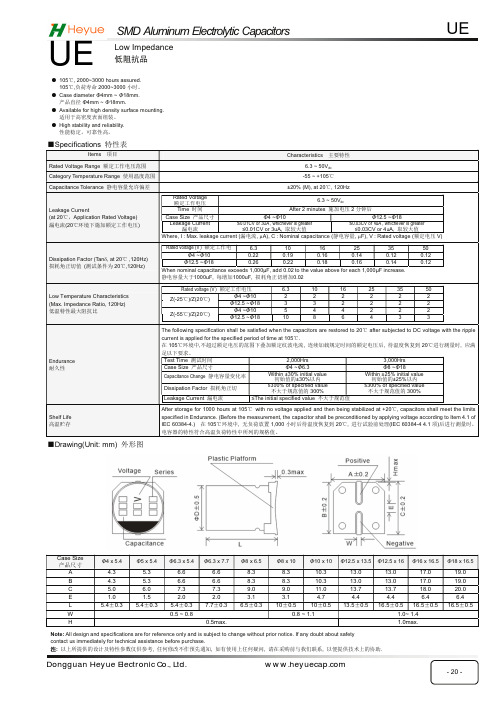
ƵDrawing(Unit: mm) ཆᖒമ
The following specification shall be satisfied when the capacitors are restored to 20ć after subjected to DC voltage with the ripple
SMD Aluminum Electrolytic Capacitors
UE
UE
Low Impedance ք䱱ᣍ
ƽ 105ć, 2000~3000 hours assured. 105ć,䍏㦧ሯભ 2000~3000 ሿᰦDŽ
ƽ Case diameter Φ4mm ~ Φ18mm. ӗ૱ⴤᖴ Φ4mm ~ Φ18mm.
≤0.03CV or 4uA , whichever is greater ≤0.03CV or 4uA, ਆ䖳བྷ٬
Where, I : Max. leakage current (┿⭥⍱, PA), C : Nominal capacitance (䶉⭥ᇩ䟿, PF), V : Rated voltage (仍ᇊ⭥ V)
6.3 ~ 50Vdc
Category Temperature Range ֯⭘ᓖ㤳ത
-55 ~ +105ć
Capacitance Tolerance 䶉⭥ᇩ䟿ݱ䇨ٿᐞ
±20% (M), at 20ć, 120Hz
Leakage Current (at 20ćˈApplication Rated Voltage) ┿⭥⍱(20ć⧟ຳлᯭ࣐仍ᇊᐕ⭥)
95 6.3x5.4 1.0 140 6.3x5.4 1.0 140 6.3x7.7 0.60 230 6.3x7.7 0.60 230 8x10.5 0.60 300
- 1、下载文档前请自行甄别文档内容的完整性,平台不提供额外的编辑、内容补充、找答案等附加服务。
- 2、"仅部分预览"的文档,不可在线预览部分如存在完整性等问题,可反馈申请退款(可完整预览的文档不适用该条件!)。
- 3、如文档侵犯您的权益,请联系客服反馈,我们会尽快为您处理(人工客服工作时间:9:00-18:30)。
ALUMINUM ELECTROLYTIC CAPACITORS 鋁電解電容器CHIP TYPE, STANDARD 貼片式,標準品Operating with general temperature range -40~+85°C 適用於 -40~+85°C 的常規溫度範圍 Load life of 2000 hours 負荷壽命2000小時RoHS & REACH compliant, Halogen-free 符合RoHS 與REACH ,無鹵SPECIFICATIONS 特性表Items 項目Characteristics 主要特性Operation Temperature Range 使用温度範圍-40 ~ +85°C Voltage Range 額定工作電壓範圍 4 ~ 450V Capacitance Range 靜電容量範圍 0.1 ~ 10000μFCapacitance Tolerance 靜電容量允許偏差±20% at 120Hz, 20°C Leakage Current漏電流Rated Voltage額定工作電壓6.3 ~ 100V 160 ~ 450VCase size 尺寸∅4~∅10 ∅12.5~∅18 ∅6.3~∅18 Time 時間 After 2 min. application of rated voltage at 20°C 在20°C 環境中施加額定工作電壓2分鐘後After 1 min. application of rated voltage at 20°C 在20°C 環境中施加額定工作電壓1分鐘後 After 5 min. application of rated voltage at 20°C 在20°C 環境中施加額定工作電壓5分鐘後Leakage current 漏電流 ≤0.01CV or 3μA, whichever is greater ≤0.01CV 或3μA ,取較大值 ≤0.03CV or 4μA, whichever is greater ≤0.03CV 或4μA ,取較大值 ≤0.04CV+100μA, whichever is greater ≤0.04CV+100μA ,取較大值C: Nominal capacitance (μF) 標稱靜電容量, V: Rated voltage (V) 額定電壓 Dissipation Factor (tan δ) 損耗角正切Measurement frequency 測試頻率: 120Hz, Temperature 温度: 20°C Rated Voltage (V) 額定工作電壓 4 6.310162535 50 63 100160~250350~450tan δ (max.) 最大損耗角正切 ∅4~∅100.420.280.240.200.140.12 0.12 0.10 0.100.200.25∅12.5~∅180.450.380.340.300.280.22 0.18 0.14 0.100.200.25Stability at Low Temperature 低溫特性Measurement frequency 測試頻率: 120HzRated Voltage (V) 額定工作電壓 4 6.3101625 35 50~100 160~250350~450Impedance Ratio 阻抗比ZT/Z20 (max.) ∅4~∅10Z(-25°C)/Z(20°C)7 4 3 2 2 2 2 2 3Z(-40°C)/Z(20°C)158 6 4 4 3 3 3 6∅12.5~∅18Z(-25°C)/Z(20°C)7 5 4 3 2 2 2 2 4Z(-40°C)/Z(20°C)1712108 5 4 3 6 10 Load Life 高溫負荷特性After 2000 hours application of the rated voltage at 85°C, they meet the characteristics listed below.在85°C 環境中施加額定工作電壓2000小時後,電容器的特性符合下表的要求。
Capacitance Change 靜電容量變化率 Within ±20% of initial value (Within ±30% of initial value for 4V)初始值的±20%以內(4V 為±30%以内)Dissipation Factor 損耗角正切 200% or less of initial specified value 不大於規範值的200% Leakage Current 漏電流initial specified value or less 不大於規範值Shelf Life 高溫貯存特性After leaving capacitors under no load at 85°C for 1000 hours, they meet the specified value for load life characteristics listed above.在85°C 環境中無負荷放置1000小時後,電容器的特性符合高溫負荷特性中所列的規定值。
Resistance to Soldering Heat 耐焊接熱特性(Please refer page 23 for soldering conditions) (焊接條件請查閱第23頁)After reflow soldering and restored at room temperature, they meet the characteristics listed below. 經過回流焊並冷卻至室溫後,電容器的特性符合下表的要求。
Capacitance Change 靜電容量變化率 Within ±10% of initial value 初始值的±10%以内 Dissipation Factor 損耗角正切 initial specified value or less 不大於規範值 Leakage Current 漏電流 initial specified value or less 不大於規範值 Marking 標識Black print on the case top. 鋁殼頂部黑字印刷。
DRAWING 外形圖 (Unit: mm)*1. Voltage mark for 6.3V is [6V] *2. Applicable to ∅6.3×7.7*3. Applicable to ∅8×10.5~∅10 *4. Applicable to ∅12.5~∅18 6.3V 的產品標識為 [6V] 適用於∅6.3×7.7適用於∅8×10.5~∅10 適用於∅12.5~∅18正極負極(∅4~∅6.3×7.7)(∅8×10.5~∅18)Dimension table in next page. 尺寸表見下一頁。
Series RVSDIMENSIONS (Unit: mm) 尺寸表∅D x L 4 x 5.45 x 5.46.3 x 5.46.3 x7.78 x 10.510 x 10.510 x 13.512.5 x 13.512.5 x 1616 x 16.518 x 16.518 x 18.5A 2.0 2.2 2.6 2.6 3.0 3.3 3.3 4.9 4.9 5.8 6.2 6.2B 4.3 5.3 6.6 6.6 8.4 10.4 10.4 13.0 13.0 17.0 19.0 19.0C 4.3 5.3 6.6 6.6 8.4 10.4 10.4 13.0 13.0 17.0 19.0 19.0 E ± 0.2 1.0 1.4 1.9 1.9 3.1 4.7 4.7 4.7 4.7 6.4 6.4 6.4 L5.4 5.4 5.4 7.7 10.5 10.5 13.5 13.5 16.0 16.5 16.5 18.5DIMENSIONS & MAXIMUM PERMISSIBLE RIPPLE CURRENT 規格尺寸及最大允許紋波電流ALUMINUM ELECTROLYTIC CAPACITORS 鋁電解電容器DIMENSIONS & MAXIMUM PERMISSIBLE RIPPLE CURRENT 規格尺寸及最大允許紋波電流FREQUENCY COEFFICIENT OF ALLOWABLE RIPPLE CURRENT 紋波電流頻率補償系數 Frequency 頻率50Hz 120Hz 300Hz 1KHz 10KHz~Coefficient系數∅4 ~ ∅100.1 ~ 68μF 0.70 1.00 1.17 1.36 1.50100 ~ 3300μF 0.85 1.00 1.08 1.20 1.30 ∅12.5 ~ ∅18~ 68μF 0.75 1.00 1.35 1.57 2.00 100 ~ 680μF 0.80 1.00 1.23 1.34 1.501000 ~ 6800μF 0.85 1.00 1.10 1.13 1.15The endurance of capacitors is reduced with internal heating produced by ripple current at the rate of halving the lifetime with every 5~10°C rise. When long life performance is required in actual use, the rms ripple current has to be reduced. 鋁電解電容器在疊加紋波電流後會引起發熱,溫度每上升5~10°C壽命會減半。
若要保持長壽命性能,請在使用過程中適當降低紋波電流。
ALUMINUM ELECTROLYTIC CAPACITORS 鋁電解電容器。