bts600-电池测试系统-Digatron
BTS 电池综合测试仪说明书

目录1.前言 (2)2.功能概述 (3)3.仪器外观 (5)4.接线方式 (6)5.主功能菜单 (7)6.电池静态参数测量模式 (8)7.电池容量测量模式 (12)8.单独充电模式 (14)9.单独放电模式 (14)10.程控电源模式 (14)11.程控电子负载模式 (15)12.电压与内阻表模式 (16)13.仪器校准模式 (16)14.读码功能(DS2502兼容码) (17)15.仪器特性指标 (18)前言常见的可充电电池包含锂电池,镍镉电池,镍氢电池,以及密封铅酸蓄电池等。
其中,锂电池具有容量大,重量轻,循环次数高等特点,广泛应用于移动电话,PDA,数码相机,摄像机,笔记本电脑等领域,是目前最为先进的可充电电池。
这里所指锂电池是成品锂电池包,由锂电芯(锂离子电芯或者锂聚合物电芯)加锂电池保护板组成。
镍镉电池是比较早应用的可充电电池,具有成本较低,低内阻,能够大电流放电的特点,至今在一些电动工具、电动车上面有广泛应用。
镍氢电池和镍镉电池类似,但是因为不含重金属,所以对环境的污染较小,目前在一些常见的消费类电子产品中应用广泛,已基本取代以前镍镉电池的应用领域。
小型密封铅酸电池,又称免维护铅酸电他,目前工艺成熟,目前主要应用在固定式后备电源场合,如不间断电源,应急照明灯等等场合。
针对这些可充电电池的生产检测需要,特研制了专用的可充电电池综合检测仪,本测试仪可以对电池的一些基本参数做一个定量的精确的测量,可以测量电池的开路电压,内阻,充电,放电性能,电池容量特别针对锂电池的功能还有过充电保护,过放电保护,过电流保护,短路保护等功能,并测出过相应的数值,极大的方便了电池的生产和售前售后服务工作。
采用非常简单的几个步骤就可以直观的判断电池的性能和好坏,同时也具有快速筛选的功能,可以设定测量参数的上限和下限,可以容易的从一批电池成品中快速检测出不良电池,提高生产效率。
另外,也附加了一些特别的功能,使之具有一些通用仪器设备的特征,扩大了设备的使用灵活性,以及具有应用范围广泛的特点。
思特克全在线蓄电池充放电测试设备BTS-TX300(通讯)中文说明书
深圳市思特克电子技术开发有限公司张为虎139******** or 138********BTS-TX300全在线蓄电池测试维护系统使用手册深圳市思特克电子技术开发有限公司地址:深圳市南山区西丽镇大磡村思特克工业园199号市场部电话:0755-********联系人:张为虎136********(深圳)138********(北京)网址:前言本手册依据GB/459-2000标准要求编制本手册由深圳市思特克电子开发有限公司提出,并享有最终解释权深圳市思特克电子开发有限公司保留对本产品软件、硬件及外观进行升级换代不予提前通知的权利。
未经深圳市思特克电子开发有限公司许可,不得以任何方式复制、截取、转摘、传播该规程中的内容。
本手册适用于BTS全在线蓄电池测试维护系统.本手册版本升级恕不另行通知。
请在使用设备之前仔细阅读本手册。
目录目录第1章简介 (4)第2章概述 (5)第3章功能特点 (6)第4章技术参数 (7)第5章设备运行 (8)第6章保固承诺 (18)建议 要求警告: 电池极柱、端口和有关的附件含有铅和铅的化合物,这些物品可能会引起健康方面的问题。
请在处置过后洗手!第1章 简介本操作手册介绍-48V 电池组在线放电设备BTS-TX300的主要功能和使用方法,它将帮助您正确地设定测试仪、选择测试参数、进行放电测试,以及管理测试数据;操作手册也说明了产品维护保养、品质担保以及服务等方面的信息。
安全注意事项重要事项:在使用本测试仪以前,请先阅读以下说明:注意:表示:此项有触电危险,会导致人身伤害表示:请注意此事项。
表示:本机内部不含任何备件或可替换元件,请勿打开机箱表示:本机内有危险电压,非专业人士请勿触碰。
表示:设备工作间,电压高,电流大,请勿搬运。
非专业人员请勿操作。
警告: 为了避免在测试电池过程中发生电击事故,请按安全规程进行操作,并遵守以下几点原则:∙ 戴防护眼镜或面罩 ∙ 戴橡胶防护手套 ∙ 穿防护或工作服∙ 只做您受过培训的维护工作∙ 如果没有得到获准,在测试时不要将电池组与系统断开 ∙ 避免让自己处于回路中∙ 避免接触框架及靠近金属物品,这些可能在您接触电池时接地概述第 2 章概论用于通信机房或其他不间断掉电系统的固定式蓄电池组,其最主要的功能是当市电中断或整流设备出现故障时,能提供直流电流继续维持各种电信设备的正常运行。
Amprobe UAT-600地下设施定位器系列用户说明书

Accidentally hitting a utility line during a project can lead to costly repairs and create hazardous public safety situations. Digging in the wrong place can also lead to unnecessary delays and costs for your project, and ultimately, your company. Avoid this disruption with the rugged and durable Amprobe UAT-600 Series, designed to accurately pinpoint underground utilities and buried services up to 20 feet deep.Designed for electricians with a CAT IV 600 V rating, the locating kits come complete and ready for use with a Transmitter, Receiver, test lead kit, batteries and additional fuses, all in a mobile, protective duffle bag.The UAT-620 kit also includes a Signal Clamp for transmitting a signal when it is not possible to make electrical contact with the cable to be traced. For applications where ground fault locating is required, use the UAT-600 Transmitter in combination with the optional A-Frame accessory.Intuitive Transmitter automatically chooses the correct locatingfunctionSC-600 Signal Clamp included in the UAT -620 KitLarge LCD Display with auto backlight for clear viewing in full sunlightLocateunderground utilities up to 20 ft.UAT -600 SeriesUnderground Utilities LocatorAccurately and safely pinpoint underground utilities before you digUAT -620Underground Utilities Locator KitAF-600 A-Frame Accessory*Ground Fault FinderSee page 2 for specifications* (Not included in the UAT-610 and UAT-620 Kits)Safety CertificationAll Amprobe tools, including the Amprobe UAT-600 Series, are rigorously tested for safety, accuracy, reliability, and ruggedness in our state-of-the-art test lab. In addition, Amprobe products that measure electricity are listed by a 3rd party safety lab, either UL or CSA. This system assures that Amprobe products meet or exceed safety regulations and will perform in a tough, professional environment formany years to come.Features and Highlights• Multiple tracing modes allow you to locate and trace energized and de-energized utilities in a variety of applications• The intuitive Transmitterautomatically chooses the correctlocating function based on the connectedaccessory and includes selectable 8/33kHz frequencies• The Receiver’s high-contrast display allows for clear viewing in full sunlight and features an automatic backlight for shaded and dark areas• Rated CAT IV 600 V , ensuring safety when working with energized cables • Semi-automatic gain control quickly detects tracing signal and allows precise adjustment of the receiver sensitivity• Accurate depth measurement to 20 ft• Rugged, durable construction: water and dust resistant to IP54 and drop proof to 3.28 ft (1 m)• Use the Signal Clamp to induce asignal without making electrical contact (UAT -620)• Ground fault locating with the optional A-Frame accessory • Comes as a complete kit, ready for useLCD Display with autobacklightDetect ground faults on cables and pipesAF-600-A-FrameGround Fault FinderAF-600 A-FrameGround Fault FinderSave time and money by pinpointing leakage pointsGround faults are a common problem with electrical cables. Find any fault with the AF-600 A-Frame cable ground fault finder, specifically designed for use with the Amprobe UAT -600 Series.Set up the UAT -600-T Transmitter to apply a fault find signal to the utility under test, the AF-600 A-Frame receives the signal and locates the place of the fault. The AF-600 will pinpoint where a cable metal conductor (either a sheath or a metallic conductor of the wire) touches the ground and can also detect other conductors to ground faults such as pipeline coating defects.Carrying Case, User ManualThe AF-600 comes complete with batteries and a carrying caseFeatures and Highlights • Identify any point of leakage around a cable • Locate cable and wire ground faults, sheath faults or pipeline coating defects, where the utility is in direct contact with the ground • Find the exact point where metal is touching the ground and power is leaking, ie, a shield is rusted or a rubber buffer is broken, creating noise on a cable • Advanced technology and digital signal processing makes pinpointing process fast, accurate and clear:-Compass guidance with numeric fault field strength indicates the direction of the fault -Distance sensitive left and right arrows guides the user to precisely follow the path of the buried utility-Automatic gain control quickly detects tracing signal and precisely adjusts the A-Frame sensitivity-Adjustable volume controlsClearly view the LCD display in bright sunlightPinpoint fault location by using the AF-600 with the UAT-600 TransmitterSC-600Signal ClampTL-UAT -600Test Leads KitSC-600 Signal Clamp(included in the UAT -620 Kit only)The Signal Clamp accessory provides an efficient and safe method of applying a locate signal to a cable, enabling the Transmitter to induce a signal through the insulation into the wires or pipes. The clamp works on low impedance closed circuits only.Test Leads Kit(included in the UAT -610 and UAT -620 Kits)TL-UAT -600 Test Leads Kit includes: Black test lead with detachable black alligator clip, Red test lead with permanently attached red alligator clip, Ground stakeTrace an individual utility by connecting the The Transmitter will automatically change modes The Receiver’s high contrast LED screen is easy toUAT-620 Underground Utilities Locator Kit。
莱特斯科 BT-100电池加载测试器 充电系统分析仪 产品说明书

READ THE ENTIRE MANUAL BEFORE USING THIS PRODUCT. FAILURE TO DO SO COULD RESULT IN SERIOUS INJURY.Battery Load Tester/Charging System Analyzer For 6 and 12 Volt BatteriesOWNERS MANUALIMPORTANT SAFETY INSTRUCTIONSSAVE THESE INSTRUCTIONS – This manual will show you how to use your tester safely and effectively. Please read, understand and follow these instructions and precautions carefully, as this manual contains important safety and operating instructions.WORKING IN THE VICINITY OF A LEAD-ACID BATTERY IS DANGEROUS. BATTERIES GENERATE EXPLOSIVE GASES DURING NORMAL OPERATION. FOR THIS REASON, IT IS IMPORTANT THAT YOU FOLLOW THESE INSTRUCTIONS EACH TIME YOU USE THE TESTER.WARNING: Pursuant to California Proposition 65, this product containschemicals known to the State of California to cause cancer and birth defects or other reproductive harm. Wash hands after handling.•Read the entire manual before using this product. Failure to do so could result in serious injury.•Use the tester in a well-ventilated area.• This tester is not intended for use by children.•Do not expose the tester to rain or snow.•Do not operate the tester if it has received a sharp blow, been dropped or otherwise damaged in any way; take it to a qualified service person.•Inspect the battery for a cracked or broken case or cover. If the battery is damaged, do not use the tester.•Do not disassemble the tester; take it to a qualified service person whenservice or repair is required. Incorrect reassembly may result in a risk of fire or electric shock.•Follow these instructions and those published by the battery manufacturer and the manufacturer of any equipment you intend to use in the vicinity of thebattery. Review the cautionary markings on these products and on the engine.PERSONAL SAFETY PRECAUTIONS•Wear complete eye protection and protective clothing when working near lead-acid batteries. Always have someone nearby for help.•Have plenty of fresh water, soap and baking soda nearby for use, in case battery acid contacts your eyes, skin or clothing. Wash immediately with soap and water and seek medical attention.•If battery acid comes into contact with eyes, flush eyes immediately for at least 10 minutes and get medical attention.•Neutralize any acid spills thoroughly with baking soda before attempting to clean up.•Remove all personal metal items from your body, such as rings, bracelets,necklaces and watches. A lead-acid battery can produce a short circuit current high enough to weld a ring to metal, causing a severe burn.•Never smoke or allow a spark or flame in the vicinity of the battery or engine.OPERATING INSTRUCTIONSBATTERY TESTIMPORTANT: During the first use of this tester, you will notice a little smoke and/or a burning smell. This is normal and will stop after a short burn-in period. Also, during regular use, the metal housing of the unit will get hot enough to burn skin or cause property damage; carry by the handle. Neither of these factors will affect the performance of your tester.1.Turn off the ignition, all accessories and any loads.2.Clean the battery terminals.3.Clip the red clamp to the positive (POS, P , +) battery terminal.4.Clip the black clamp to the negative (NEG. N, -) battery terminal.6V BATTERY ANALYSIS1.Read the meter and confirm the battery voltage is in the green “OK” area (see illustration).2.Press and hold the load switch “on” for a maximum of 10 seconds and read the meter with the load still on. The needle should remain in the green area.If it doesn’t, the battery is weak or bad.CAUTION: To prevent overheating, allow tester to cool for 5 minutes before depressing the load switch again, if further testing is required.12V BATTERY ANALYSIS1.Find the Cold Cranking Amps (CCA) range on the meter (see illustration)that matches the CCA rating of the battery being tested.2.Press and hold the load switch “on” for a maximum of 10 seconds and read the meter with the load still on. Then, refer to T able 1 or the back of the tester.CAUTION: To prevent overheating,allow tester to cool for 5 minutes before depressing the load switch again, if further testing is required.TABLE 1LOAD TESTBATTERY CONDITIONGood (green)The battery capacity is OK. The battery may or may not be fully charged. Check the specific gravity of the battery to determine the state of charge, check for an electrical drain or possible charging system trouble. Recharge the battery to a full level.Weak or bad, but the needle remains steady. (yellow or red) The battery capacity is not satisfactory. The battery may be either defective or not fully charged. Check the specific gravity to determine which condition exists. If charging doesnot bring the specific gravity to the full charge level, the battery should be replaced.Weak or bad, but the needle continues to fall. (yellow or red)The battery may be defective or very run-down. Release the load switch and note the voltmeter reaction. Voltage recovery to 12 volts or above within a few seconds indicates a defective battery. A slow voltage recovery indicates a run-down condition. For best results, check the specific gravity.1.Connect the tester.2.Start the engine and run it at 1200 to 1500 rpm. CAUTION: Stay clear of moving engine parts.3.Note the meter reading with all of the electrical accessories off. It should be in the green “OK” band in the “charging system” scale (see illustration).4.With the headlights and blower motor on high, the meter should remain in the green “OK” band.5.If the meter reads in the red band or outside the charging system zone,trouble is indicated; most likely a defective alternator.1. Range for 6 volt battery load testing2. Range for 12 volt battery load testing3. Cold cranking amps range4. Charging system test range5. Voltage scale6. Starter test voltage table123456STARTER MOTOR TESTThis test identifies excessive starter current draw, which makes starting difficult and shortens battery life. Perform the battery load test first, to make sure the battery is in good condition. If the battery tests either weak or bad, this test cannot be performed.NOTE: The engine must be at a normal operating temperature.1.Perform a basic battery load test. Note the exact voltage with the load test on (see meter illustration).ing the load voltage obtained above, see Table 2 or the meter face, to find the minimum cranking voltage listed. If the engine is less then 200 CID,use the next higher minimum cranking voltage. For example, if the load voltage is 11.00, use 10.2 for the minimum cranking voltage instead of 9.7.3.If possible, disable the vehicle’s ignition system so that it will not start. The test works best if the starter cranks for 2 to 5 seconds.4.Crank the engine and note the voltage reading during engine cranking.5.If the cranking voltage is below the minimum cranking voltage in Table 2,the starter current draw is excessive. If the starter cranks slowly, check for high resistance or poor connections.TABLE 2STARTER TEST VOLTAGELOAD VOLTAGE 10.210.410.610.811.011.211.4MINIMUM CRANKING VOLTAGE 7.78.28.79.29.710.210.6。
PJB D-600 低音电子设备说明书

PJB D-600OWNER’S MANUALThank you for purchasing the PJB D-600. A great deal of dedication and passion went into designing and building this no compromise, high performance compact amplifier. It was conceived to be a dedicated amplifier for the “connoisseur” bassist. Reading this manual will enable you to get the best performance from it so that you may enjoy many years of service.READ THIS FIRST•Before using the D-600 please read ALL the instructions.•On receipt of product, check for any signs of physical damage arising from shipping. If any damage is visible contact your dealer.•Keep all original packing.•Do not use this amplifier in a way that would compromise its ventilation system.When operating, never cover the heat sink on rear panel.•Do not locate this amplifier near any heat source.•This amplifier must be connected only to a power source specified in this manual.•For safety do not leave the amplifier plugged into a power source for long periods of time when not in use.•Do not let any liquid or foreign objects fall into any openings on the amplifier.•Never use this amplifier if it has:1. Suffered any physical damage.2. Been subjected to any liquids, rain or moisture.3. Damaged cables connected to it.If any of the above occurs, the amplifier should be examined by qualified servicepersonnel.•Always operate this amplifier with the correctly rated fuse.•Never use this amplifier without proper grounding.•The mains plug is used as disconnect device, the disconnect device shall remain readily operable.•Protective earthing terminal. The apparatus should be connected to a mains socket outlet with a protective earthing connection.• Correct Disposal of this product. This marking indicates that this product should not be disposed with other household wastes throughout the EU. Toprevent possible harm to the environment or human health fromuncontrolled waste disposal, recycle it responsibly to promote the sustainablereuse of material resources.•The apparatus shall not be exposed to dripping or splashing.FRONT PANEL AND BACK PANEL OVERVIEWFRONT AND BACK PANEL DESCRIPTION1. INSTRUMENT INPUT JACK CHANNEL AThis is a standard ¼ inch mono jack socket. This is a high impedance input that can be used with Piezo pickups on double basses.2. CLIP/ MUTE INDICATORWhen the amplifier output is clipping, the LED will light up with red. When muted, the LED will light up with green.3. INPUT GAIN SWITCH CHANNEL AHigh: Higher sensitivity, high impedance input.Low: Lower sensitivity input setting for guitars with onboard electronics.Mute: mute the input stage, when switch on, the clip LED will light up with green.4. INPUT LEVEL SENSITIVITY CHANNEL A5. LOW BASS EQ CONTROL.This will adjust the fundamental tones of E and A strings on 4 string basses and B, E & A on 5 string basses.6. BASS EQ CONTROL.This will adjust the fundamental tones of D and G-strings on 4 & 5 string basses.7. MID RANGE EQ CONTROL.8. LOW TEBLE EQ CONTROL.9. HIGH TREBLE (PRESCENCE) EQ CONTROL.10. COMPRESSOR THRESHOLD LEVEL CONTROL.This will vary the level the limiter threshold. The compression ratio is 3dB to 1. Adjust this to suit your playing style and output power of your instrument. The blue LED will light up when the signal is being compressed. This will vary on how hard the instrument is played and how the threshold is adjusted.11. AUX INPUT VOLUME CONTROLUse to control the level of backing/rhythm track.12. HEADPHONE OUTPUT JACKThis jack accepts ¼ inch stereo headphone jacks.13. MASTER VOUME CONTROL.This is the master volume control and it controls how much power you send to your speakers as well as the line out socket on the back of the amp. When setting up your tone or plugging in your instrument, you should keep this control at a low level. All instruments are different when it comes to how much output is from the pickups. Likewise for players, depending on how hard or soft you play.14. INSTRUMENT INPUT JACK CHANNEL BThis is a standard ¼ inch mono jack socket. This is a high impedance input that can be used with Piezo pickups on double basses.15. CLIP/ MUTE INDICATORWhen the amplifier output is clipping, the LED will light up with red. When muted, the LED will light up with green.16. INPUT GAIN SWITCH CHANNEL AHigh: Higher sensitivity, high impedance input.Low: Lower sensitivity input setting for guitars with onboard electronics.Mute: mute the input stage, when switch on, the clip LED will light up with green.17. INPUT LEVEL SENSITIVITY CHANNEL B18. LOW BASS EQ CONTROL.This will adjust the fundamental tones of E and A strings on 4 string basses and B, E & A on 5 string basses.19. BASS EQ CONTROL.This will adjust the fundamental tones of D and G-strings on 4 & 5 string basses.20. MID RANGE EQ CONTROL.21. LOW TEBLE EQ CONTROL.22. HIGH TREBLE (PRESCENCE) EQ CONTROL.23. LIMITER IN/OUT SWITCH.Sends signal through limiter or bypass.24. COMPRESSOR INDICATOR.This blue L.E.D (Light Emitting Diode) will light up when the signal is being compressed. This will vary on how hard the instrument is played and how the threshold is adjusted.25. AUX INPUT JACKStereo input for Drum machine or I-pod/MP3 player.26. LINE INPUT.Input matched to accept high-level outputs from other bass/guitar pre-amps. This input is a direct feed to the power amp and does not pass through limiter or EQ sections.27. POWER ON/OFF SWITCH.This switches the main power on and off in the amplifier. When you turn on the power, it will have about 2 seconds delay to protect the speaker.Do not leave the amplifier plugged into a power source for long periods of time when not in use.28. AC INPUT -VOLTAGE SELECTOR.Switches the amplifier to run on either 110-115volt or 220-240volt AC power. Never try to run the amplifier on a 220-240volt supply when switched to 110-115volt. This can possibly cause major damage to the amplifier.29. AC INPUT SOCKET & FUSE.Connects the amplifier to AC power supply. Always use a grounded plug and make surethe AC cable is more than 3A rating at 250-volt AC. If you require a longer AC power cord, we recommend the PJB heavy-duty 20 foot power cords. These are available as an accessory. If fuse needs replacing, use a slow blow ¾ inch fuse.30. BALANCED LINE OUT.This is an ultra-low impedance (200Ω) balanced line out for use with recording or PA mixing consoles. This output is not controlled by the volume control. Changing the level on your instrument will however, vary the DI output.31. GROUND LIFT SWITCH.This allows the grounding of balanced out socket to be disconnected. This is useful if you are experiencing hum caused by grounding loops/problems.32. TUNER OUTConnect to instrument tuner. This output can also be used as an additional line out.33. PRE-AMP OUT.Can be used for driving a second amplifier.34. FX SEND SOCKET.Connect the FX send to auxiliary FX unit input.35. FX RETURN SOCKET HIGH.Connect the FX Return to auxiliary FX unit output.36. LOUDSPEAKER OUTPUTS (NEUTRIK SPEAKON CONNECTORS).The D-600 amplifier will work on any load from 16Ω down to 2Ω, which is the safe maximum load for this amplifier. The ‘Speakon’ sockets are in parallel so connecting two 8Ω speakers will result in a 4Ω total load. We recommend that you use PJB high current speaker cables: which are dedicated high-current, low-resistance cables. Using inferior cables will greatly impair the performance of your system.Just to avoid any confusion, a speaker that has a low impedance has a greater load on the amplifier. So a maximum load refers to a minimum speaker impedance as more current is flowing through the amplifier’s output stage, speaker cables and cabinets.OPERATION & POSITIONINGTURN THE VOLUME DOWN on the D-600 before plugging in your instrument.Connect the speaker or speakers to the D-600. For best results with this amplifier you should use PJB loudspeaker cabinets and PJB cables.ALWAYS USE A HIGH QUALITY GROUNDED AC POWER CABLE. NEVER USE THIS AMPLIFIER WITH THE GROUND CONNECTION REMOVED. We recommend you use PJB cables for speaker connections as they have virtually no loss so there is maximum transfer of power from amplifier to speaker.Setting Up the LimiterAlthough a limiter is not essential to bass amplification, it can be a useful tool in smoothing out the character of your instrument or playing style. The D-600 limiter has a preset compression ratio of 3 to 1. For each additional increase of 3dB above the set threshold, the increase in level is actually 1dB. So the dynamic range of your instrument is reduced.First set up the limiter by having the compression control (10) set fully clockwise. Now switch on the limiter (23). Start playing and turn control (10) counter-clockwise. You will see the blue light start to come on and that is the indication that the limiter is now working. Set this control to suit your taste.TRANSPORTING AND STORING THE D-600When transporting or storing the D-600, it is recommended that you always use the gig bag provided. That will ensure that you amp has the best protection from dust and will stay looking like new.When Storing:•Keep in a dry location preferably at room temperature in the gig bag.•Do not store in temperatures below -20 Degrees C or above 40 Degrees C.•Do not allow it to get wet. If this occurs, never turn it on in this condition.•Do not leave the D-600 permanently connected to a power source.SPECIFICATIONS AmplifierPJB 600watt, D class amplifier with digital switch mode power supply. Frequency Response30Hz -25KHzSignal to Noise RatioBetter than 90 dB (EQ off, Volume on Full.)ImpedanceHigh Input: >4MΩ/22pFLow Input: >100KΩ/22pFLine Input: >75KΩPre Amp Line Out: < 2KΩBal. Out: <200ΩLevelsHigh Input: 10mV-2.5VLow Input: 20mV-5VPre Amp Out: 1.2VFX send: 1VBal. Line Out: Typical 500mVCompressor / LimiterGain: 0dBCompression Ratio: 3dB: 1dBEQ CENTER FREQUENCIES50Hz, 160Hz, 630Hz, 2.5KHz, 12KHz at +/- 18dBIncluded Parts6 ft AC Power Cord.Padded gig bag with shoulder strap.SERVICE/WARRANTY INFORMATIONIN USAThe D-600 has a limited warranty period of 2 years, starting from the date of purchase. The buyer must complete and return the enclosed warranty card within 14 days of purchase. In other countriesPlease contact the local distributor as other warrantee terms may apply.This warranty covers defect in materials or workmanship that occurs in normal use. Within warranty period PJB will repair or replace the defect unit free of labor and parts charge. It is the buyer’s responsibility to use the unit strictly according to instructions written in this manual and amplifier manual.This warranty is not transferable; it is provided to original owner only. Damage/defectscaused by the following conditions are not covered by this warranty:•Improper handling, neglect or failure to operate the unit in compliance with the instructions given in user manual;•Connection or operation of the speakers in any way that does not comply with the technical or safely regulations applicable in the country where the product is used;•Repairs or modifications by anyone other than authorized PJB service agent; •Damages/defects caused by force majeure or any other condition that is beyond the control of PJB.Should you need any warranty service, please bring the D-600 back to the dealer from whom you purchased, along with your sales receipt. Depending on the complexity of the repair work, your dealer may return the defect unit to PJB service center for repair or replacement.Phil Jones BassAmerican Acoustic Development LLC8559 Page AvenueSt. Louis, MO 63114 USAPhone: 314 814 3383Fax: 636 536 1338******************************Phil Jones Bass is a division of American Acoustic Development LLC.。
ZDOY ZD-BT600携式蓄电池内阻测试仪 说明书

ZD-BT600便携式蓄电池内阻测试仪使用说明书目录一、产品概述 (2)二、产品简介 (2)2.1 监测装置构成 (2)2.2 装置简介 (3)2.3 键功能 (3)三、操作说明 (4)3.1 测量准备与连接 (4)3.1.1 测试准备 (4)3.1.2 连接电池 (5)3.2 测量操作 (10)3.2.1 设定时间 (11)3.2.2 测量过程 (11)3.2.3 设定存储器配置 (17)3.2.4 设定测量参数 (18)3.2.5 清除存储器 (20)3.3 提示与报警 (21)3.4 附录 (25)四、保养维护 (27)4.1 运行时的维护 (27)五、运输与贮存 (27)5.1 运输注意事项 (27)5.2 贮存注意事项 (27)六、开箱及检查 (28)6.1 开箱注意事项 (28)6.2 检查事项 (28)七、服务与支持 (28)一、产品概述蓄电池内阻测试仪是北京中电欧亚科技有限公司专为通信、电力系统的铅酸蓄电池放电维护而设计的新型高科技智能产品,为直流系统用户提供一个安全可靠、快捷便携的检测设备。
该装置集检测技术、数字信号处理技术、计算机控制技术、通信技术于一体,是北京中电欧亚科技有限公司研发人员经过多年与电池专家和电池用户在收集分析了国内外大量技术资料后,共同研究开发出的新一代电池运行监测装置。
广泛应用在电力直流系统、电信机房和无人值守基站、数据中心等不间断电源场合,对后备蓄电池串进行在线监测管理,及时发现异常电池和落后电池,并为用户提供维护方案,确保电源系统的可靠运行。
北京中电欧亚科技有限公司立足电力领域,坚持走专业化发展道路,坚持以技术先进、提供优质服务来推广公司产品,提供更完善周到的客户服务。
蓄电池内阻测试仪主要具有以下优越性能 :¾采用直流大电流内阻、连接电阻测试¾结构紧凑、携带便捷¾多种测试夹可选,适用各式电池检测¾按键少,操作简单¾自动汇集历史数据,自动生成测试报告¾强劲的后台分析软件,快速估算电池状况二、产品简介2.1 监测装置构成¾蓄电池内阻测试仪¾测试包¾测试夹¾充电器¾通信电缆¾蓄电池数据管理系统软件¾蓄电池数据管理系统软件使用说明书¾CRM1000型蓄电池内阻测试仪使用说明书2.2 装置简介本装置机箱前面板左侧是高亮低功耗液晶屏,右侧是21键键盘。
Digatron电动车辆电池测试系统.pdf
動力電池組及管理系統試驗方案型號規格:非標用途:用於電動汽車用氫鎳電池的綜合性能測試,在功率允許範圍內,可以完成所有充放電專案的性能測試。
一、購置理由:動力電池及管理技術已經成為制約電動汽車及混合動力汽車發展的瓶頸之一,動力電池台架通過容量測試試驗、效率試驗、迴圈工況試驗、電池模型參數識別試驗以及電池檢測精度和荷電狀態估計試驗等,能夠得到動力電池組的工作特性,確定其合理的工作範圍,驗證電池管理系統的電池檢測精度和能量狀態估計的準確性,為電池組裝車後有效管理提供試驗依據。
本著提高效率,減輕工作強度,降低企業成本,便於對動力車輛電池動態應力迴圈工況測試的角度考慮,該方案擬運用迪卡龍電動車輛測試系統硬體設備EVT-500-500,BTS-600電池測試軟體對電動汽車用氫鎳電池的綜合性能進行測試。
二、技術要求及設備選型情況1.技術要求1.1 主要技術指標1.1.1 充電電流:充電電流範圍: 1.0~100A(盡可能靠上限);電流解析度:0.1A,電流控制與測量精度:0.1A1.1.2充電電壓範圍:0~500V(電位器調節,最大調節電壓500V)顯示電壓解析度: 0.1V電壓控制測量精度:0.1V(硬體控制0.01V)1.1.3充電容量:系統在充電過程中對電池的充電容量計算,誤差≤±1.5%,測試電池組在不同溫度、不同放電率下所能放出的能量。
放電倍率一般為C/3、C/2、1C、2C、3C、4C等,其中C為電池組容量,溫度根據電池使用環境要求,一般為-25°C、-10°C、0°C、25°C、50°C等。
1.1.4 充電通道及方式:160CH電池組充電通道,每個電池組充電通道,通過提供的專用插頭,與電池組連接,獨立地對電池組中的最多4枚12V單體電池進行充電。
1.1.5 提供的專用插頭,在與電池組連接充電時,需確保電池組中的單體電池,處於獨立的非串聯方式。
锂离子电池和电池组的产热功率分析和仿真

锂离子电池和电池组的产热功率分析和仿真温度对于锂离子电池而言非常重要,低温会导致锂离子电池的电性能降低(容量、倍率性能),但是能够提高锂离子电池的存储寿命,高温能够提升电性能(容量、倍率性能),但是会降低电极/电解液界面的稳定性,引起循环寿命的快速衰降。
对于一个由众多电池组成的电池组而言,电池组内部的温度不均匀分布会导致单体电池的性能产生很大的差异,从而导致单体电池之间不均匀的衰降,最终导致电池组的失效,例如北京大学的Quan Xia等人采用A123的LFP电池进行电池组的模拟和仿真试验发现,通过改变电池组的结构,将电池组内的最大温差从4.62K降低到2.5K能够将电池组累计充电600Ah后的可靠性从0.0635提高到0.9328(详见链接:《电池组“可靠性”的影响因素和模型计算》)。
锂离子电池的使用工况对于离子电池的产热具有很大的影响,例如高倍率充放电会在电池内短时间累积更多的热量,而小倍率下则几乎能够实现热平衡,减少电池的温升。
江苏大学的徐晓明(第一作者,通讯作者)等人对55Ah单体电池和电池组的产热功率和温度分布情况进行了研究分析,研究表明单体电池的发热功率会随着环境温度的升高、电池SoC和充放电倍率的降低而降低,对电池组的热分析发现温度最高的区域集中在电池组中央区域,并且发现采用空气散热时气流更容易从电池组的上方流过,因此导致冷却效果不佳。
试验中作者采用了55Ah的方形锂离子电池,电池共有5个测温点,其中两个位于电池的低部、三个位于锂离子电池的侧面,如下图a所示。
电池的产热可以通过温升和电池的比热容来计算(如下式所示),其中Q为电池产热量,C为电池的比热容,m为电池的质量, T为电池的温升,如果进一步将p下式除以时间t,我们能够得到电池的产热功率。
为了保证环境温度的一致,作者采用恒温箱进行精确控温,电池的充放电设备采用了Digatron BTS-600设备,采用安捷伦的34970A设备采集电池的温度信息。
BT-100电池加载测试器说明书

00-99-000437/0804
WARNING: Handling the cord on this product or cords associated with accessories sold with this product, will expose you to lead, a chemical known to the State of California to cause cancer and birth defects or other reproductive harm. Wash hands after handling.
Weak or Bad, But Needle Remains Steady (Yellow or Red)
Battery capacity is not satisfactory. Battery may be either defective or not fully charged. Check specific gravity to determine which condition exists. If charging does not bring specific gravity to full charge level, battery should be replaced.
This limited warranty is void if the product is misused, subjected to careless handling, or repaired by anyone other than the manufacturer or its authorized representative.
高精度数字重力仪双电池供电系统设计

效应管!型号为 <6))!$@T!其 $@<"UE#在!V<W>',? 时!只 有"'"&!!@<最 大 !" ?'@A@L? 引 脚 通 过 $@A#和$@A!实现 @A输入电压的分压!判断适配器电 压是否正常!本方案设计 @A电压#!'$?!$@A#阻值 取 值 为 #!'# P!依 据 公 式 $B! W#!'#%,!VUU@+ "#'!#,!#.#-!计算出 $@A!阻值为##&P(B@L? 引 脚通过$B#和 $B!实 现 智 能 锂 电 池 输 入 电 压 的 分 压! 判断电池是否欠压!本方案设计智能锂电池电压不低
#数字重力仪双电池供电系统硬件设计 !'#关键器件部件选型 !'#'#D/A#>-)电源管理芯片
D/A#>-)是一 款 面 向 单 电 池 和 双 电 池 笔 记 本 电脑及其他便携式设备的整体电源管理解决方案的 芯片D/A#>-)可 将 来 自 多 达 两 个 电 池 组 和 一 个
收稿日期!"#) #" ") 作者简介秦佩#)*-.男山西怀仁人硕士工程师主要从事地质勘探仪器重力仪磁力仪的研发生产工作/01
电池综合测试仪操作指引

电 池
电池测量接法
注意事项
电池综合测试04
品牌 使用部门
泰斯电子 IQC检验室
发行日期 编制
版本 审核
操作指引
一、控制面板按键说明(序号与左图编对应)
(1)显示屏
(2)取消/返回
(3)向上键
(4)确认、开始、暂停
(5)左键数值减少 (6)向下键 (7)右键数值增加 (8)测试端口
示意图
编号 批准
23
二、操作界面功能说明 1.Static Test》》》》静态参数测试 2.Capacity Test 》》》电池容量测试 3.Battery charge》》》电池单独充电功能 4.Battery discharge》电池单独放电功能 5.Program DC Power》》程控直流电源 6.Program E-load》》》程控电子负载 7.VOL and IMP》》》》电压和内阻测量 8.Enter Calibration》进入内部校准程序 9.Read DS2502》》》》读DS2502兼容码片
5
1 8
三、操作步骤 (1)打开电源 (2)选择测试项目 (3)根据承认书规格参数调节测试参数 (4)将电池安右图放式连接 (5)按ENTER键开始测试
4
6 7
四、注意事项 1、电池安装时应注意电池极性,严禁将极性装反,否则会造成电池 严重损坏。 2、在电池测试过程中,每个测试通道会工作在不同的状态和不同的电流模式,严禁将 通道的电池和测试电极连接。同一个通道电池夹具和测试端口是并联关系,严禁同时 3、测试电极一定要严格对准电池电极,防止测试电极将电池的正负极短路,造成电池 4、使用前确认认仪器是否有进行有效接地 4、仪器表面不能堆放物料、杂物 5、每天上班前整理好5S
不同种类有机添加剂对铅酸蓄电池性能的影响
44能源技术0 引言 木质素和人工合成的膨胀剂将会作为一种负极的膨胀剂对铅酸蓄电池的性能产生很大的影响。
甚至能够在负极活性物质中起到较好的分散的作用,甚至能够在低温的状态下保持放电的性能。
但是如果一旦膨胀剂被运用于活性物质中,则会增加表面的吸附作用。
这样也就能够有效地避免在充电和放电的过程中出现负极活性物质的收缩。
如果能够在一定量的负极活性物质中加入膨胀剂,并在之后降低电池内部的电流密度。
但是,目前业内的木质素和与铅酸电池原料相关的物质种类很多,内部的成分也非常复杂。
1 研究的背景 目前,大家都以自己的经验来选择合适的木质素。
但是,从实际执行的情况来看,同时选择就能够在短时间内提高本身放电的性能,并在短时间内提高器具充电能力和接受能力。
目前,在行业的发展过程中将会有更多种类的木质素和磺酸盐。
不仅其内部的成分非常复杂,且内部也会合并很多的膨出剂。
所以让很多厂家不能够直接选择合适的添加剂。
因此,本文先研究不同种类的添加剂,并筛选出针对低温高倍率放电性能较为有利的膨胀剂的种类,并更好地为选择合适的膨胀剂来提供有效的指导依据。
2 铅酸蓄电池的概述 铅酸蓄电池主要是由铅和氧化物组成的一种电池,内部电解液的主要成分为硫酸溶液。
在放电的状态下,电池正极的主要成分为二氧化铅,负级的成分主要为铅。
如果给铅酸蓄电池充电,则其正负极的主要成分为硫酸铅。
铅酸蓄电池主要是由正极板、负极板、电解液、隔板、电池槽、电池盖和其他结构组成。
排气式铅酸蓄电池的电极主要是由铅和铅的氧化物组成的,其内部电解液的主要成分将会表现为硫酸的水溶液。
铅酸蓄电池的主要优点为电压显得较为稳定,且价格也较为便宜。
但是铅酸蓄电池的比能较低。
不仅寿命比较短,且日常维护的过程比较困难。
老式的铅酸蓄电池的寿命一般为2年,且在实际操作的过程中都需要定期检查内部的内容。
但是随着科技的不断进步,铅酸蓄电池的寿命将会变得更长,而且维护的过程也会变得更加简单。
3 铅酸蓄电池实验仪器和试剂 本次实验所使用的试剂和仪器主要由如下几点组成:第一,采用Digatron BTS-600电池测试系统合并新威电池测试系统。
bts600-1
Scandinavia
Källström Engineering AB Åkerivägen 19A 241 38 Eslöv Sweden Phone +46 40 671 1206 Fax +46 40 671 1205 bj@
Czech Republic/Slovakia
The Americas
Firing Circuits Inc. Sales Office 7959 Poppy Hills Lane Port Saint Lucie, FL 34986 John Mills (772) 882-4631 Office (203) 858-5922 Mobile jmills@
Adressen / Addresses
Digatron Industrie-Elektronik GmbH
Tempelhofer Str. 12-14 52068 Aachen, Germany Phone +49 241 16809-0 Fax +49 241 166465 info@digatron.de
Rev. 21.10.10
Korea
Rasan Enterprise Corp. #1004, Eno-Plazatel, 1129-19, Guwol-Dong, Namdong-Gu Incheon 405-835, South Korea Phone +82 32 438 3347 Fax +82 32 438 3348 gabyeolkim@
India
Ador Powertron Ltd. Plot 51 D-II Block MIDC Ramnagar Chinchwad Pune 411 019 Phone +91 20 27472532 Fax +91 20 27475817 prad62@dataone.in gdadkar@
Digatron( 迪卡龙 )BDBT 双向电池模块测试设备
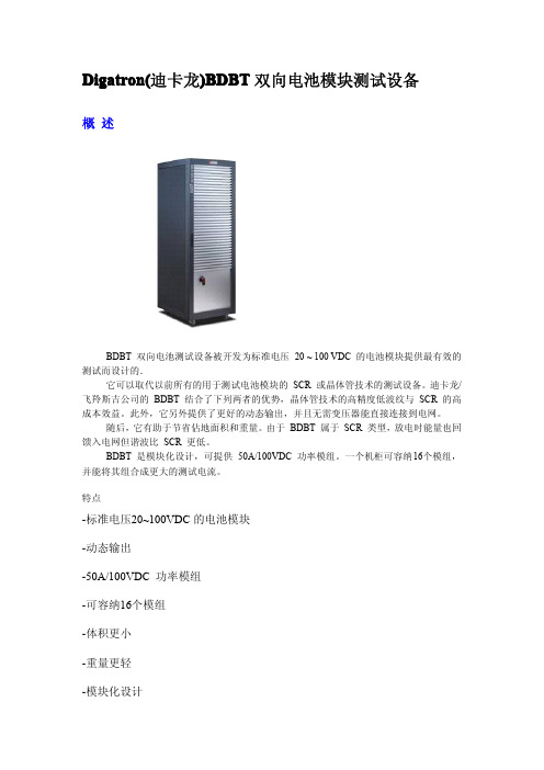
参数
一般数据
控制介面: 电脑软件: 交流功率因素: 交流谐波失真: 直流输出精度,电压: 直流输出精度,电流: 直流输出精度,分辨率
直流输出电压/电流:
数据采集率: 控制速率: 直流电流纹波: 电源供应: 环境温度:
BTSME 电池管理或 BTS-600 > 99 % 无单个谐波 > 3%. ± 100 mV / 0.1 % 全程 ± 50 mA / 0.1 % 全程 ± 15 位 0 至 100 VDC / -50 至 +50 ADC 100 毫秒 2 毫秒每电路 ± 0.5 Arms / 1 %全程 3相, 50/60 Hz 10°C - 40°C (50-104 °F)
Shenzhen Baolifa Electronics Technology Co.,TD.
电话:0755-83708496-822 (20线) 传真:0755-83711558
E-MAIL:info@ W E B:
在线联系方式
QQ:1528938208 1559690577 1584740814
选项
• 附加电压、温度 • 电池退出/旁通介面的模拟输入 • 辅助装置的输入输出 • RS232, CAN 介面
应用
BDBT 双向电池测试设备是为测试 100 VDC 的电池模块而设计的。
除了标准测试如寿命循环、容量之外,它特别适合模拟驱动循环或以高度动态负载变换和高 度动态充放转换的模拟试验。
深圳市保利发电子科技有限公司
贸易通 ID:blfkj
地址:深圳市福田区梅华路105号国际电子商务产业园科技楼301室
Digatron(迪卡龙)BDBT 双向电池模块测试设备
概述
BDBT 双向电池测试设备被开发为标准电压 20 ~ 100 VDC 的电池模块提供最有效的 测试而设计的.
BTS 高精度电池测试系统说明书

十三、智能的掉电保护措施 在电池测试过程中,任何时候出现供电系统停电或掉电,本测试系统均能保证不丢 失数据,重新上电后,测试系统具备自恢复功能,能从上次掉电的地方无缝接续,继续 测试过程。
2
BTS 系列 高精度电池测试系统使用说明书
BTS 系列 高精度电池测试系统使用说明书
BTS 月
BTS 系列 高精度电池测试系统使用说明书
使用环境参数要求: 1.使用场所:室内 2.工作温度:5℃~45℃ 3.性能保证环境温度:25℃±10℃ 4.相对温度:20%~80% 5.大气压力:1.01×10^5P
3
BTS 系列 高精度电池测试系统使用说明书
警 告 : 1. 2. 3.
4.
使用测试设备前,请仔细阅读本说明书中的安全事项。 不正当的测试操作,会导致电池损坏或者发生危险。 设备在测试中,设备外壳必须接地,以确保安全正常工作。 设备在通电中,不得强行拆拔器件,否则会导致设备损坏
BTS 系列 高精度电池测试系统使用说明书
第一章
简介
BTS 系列高精度电池测试系统是针对锂聚合物、锂离子、镍氢、镍镉、铅酸等电池 而研制的新一代通用型电池测试系统。该系统支持包括材料研究、电池循环测试、电池 化成、容量分选、组合电池测试、成品电池测试、电池测试数据处理等电池测试领域的 绝大部分应用。 根据锂离子电池测试标准,锂离子电池在恒流充电后必须经过一个恒压充电过程, 才能将电池充满(大约有 10-20%甚至多的电能是靠恒压充电充入的),因此,BTS 系列 电池测试系统为每个电池通道设有独立的恒压源及恒流源,恒压源及恒流源均可任意编 程控制,这就为锂离子电池测试提供了符合国际测试设备标准的硬件平台。 另外,针对动态内阻测试的需求,每一电池通道可增设独立的脉冲源。 BTS 系列电池测试系统采用模块化结构,系统可升级性好。
艾顿DC电源解决方案3G访问电源解决方案-APS6-600系列说明书

3G Access Power Solutions - APS6-600 SeriesFeatures∙19” sub-rack∙Compact 6U system∙Up to 6 rectifier modules∙Pre-configured software∙High power density (48V: 360A, 6U, 19”)∙Multiple AC option (1Ø, 3Ø, 2Ø)∙Fast on-line expansion of rectifiers (hot-swap)∙High efficiency and unity power factor∙Priority and non priority options for DC distributions∙Compatible with Eaton’s Network Energy Saver (ES) Rectifier 48V secure DC power up to18kW.The Eaton® 3G Access PowerSolutions are ideal for low tomedium power telecommuni-cations applications, offeringcompact, efficient, flexible andreliable secure DC powersupply.This 19” rack mount system isavailable with up to 6 of theEaton 3G, NPR48-ES Networkpower rectifier modules with atotal output up to 360A. Forsuperior operating efficiency tofurther reduce operating costs,this system is offered asstandard with Eaton EnergySaver (ES) Network powerrectifier which providesoperating efficiency in excessof 96%.The systems include an integralDC distribution panel with arange of MCB and Low VoltageDisconnect (LVD) optionsavailable.The SC200 series of systemcontroller offers highlyadvanced control andmonitoring features includingSmart Alarms – a configurablelogic for automated site energycontrol. The SC200 also offers acomplete array ofcommunications options withEthernet, GSM cellular(including text messaging),standard modem and TCP/IPcommunications options. Theslightly lower specificationSC100 is also available.Typical applications includeproviding secure power forcustomer premises equipment,roadside terminals, datanetworks and IP routers. The3G Access Power Solutions arepre-configured and all systemsettings are fully adjustable insoftware and stored intransferable configuration filesfor repeatable and quick one-step system set-up.Email:***************** Internet: Eaton, CellSure, SiteSure, DCTools and PowerManager are trade names, trademarks, and/or service marks of Eaton Corporation or its subsidiaries and affiliates. All other trademarks are property of their respective owners.© 2014 Eaton Corporation All Rights Reserved APS6-600 A1Technical SpecificationsInputAC Supply† 100 – 240V, 50 – 60Hz (nominal)185 – 275V full power output up to 50°C [122°F]90 – 185V reduced power outputPower Factor† >0.99 (50 – 100% Output Current)Efficiency† NPR48-ES : >96% peak,>95% (20% to 100% load, 230Vac) OutputDC OutputVoltage Range43.2-57.5VDC Output Power (maximum)* 48V: 18kW* Ratings are stated without LVDs fitted. In some cases lower ratings may result when LVDs areused. Refer to installation guide for detailed load specs and MCB derating factors.EnvironmentalOperating Temperature Range* -40°C to +70°C [-40°F to +158°F]* Refer to rectifier data sheet for more information. Output current is derated above 50°C [122°F] and below -10°C [14°F]MechanicalDimensions H,W,D 6U, 19” mounting, 335mm [13.2”]** Additional clear space is required for exhaust air.SystemSystemControllerSC200, Option for SC100DC Distribution Module 20-way circuit breakers(4 x battery, 16 x load)Communication Features USB direct*10BaseT Ethernet*, TCP/IP*, SNMP*, Modbus-TCP*, Modbus-RTU* and on board web server* RS232 to external PSTN or GSM modem (modem not included)*SC200 onlyLow VoltageDisconnect(LVD)Optional 400A LVDs for battery or load, or both.Rectifier BlankPanelsFor unused rectifier positionsOptions External Surge Protection† Power factor, efficiency, AC voltage range and output power are dependent on the rectifier module. Refer to the rectifier data sheet for more information..SoftwareDCToolsConfigurationsoftware.Free download from:/downloads PowerManagerII Remote control and monitoring softwareCertificationsCEIn the interests of continual product improvement all specifications are subject to change without notice.。
BTS20单体电芯测试设备使用手册说明书
股票代码:870725适用于BTS20单体电芯测试设备衷心感谢您购买德普测试设备!为确保您安全使用本设备及令本设备更加持久请在使用本设备前,认真阅读本使用手册,并请正确操作本使用手册请保留备用BTS20单体电芯测试设备BTS20 SINGLE CELL TEST EQUIPMENTmade inEOL模组测试工作站模组充电测试平台模组测试工作站成品自动测试生产线PACK自动产线▶▶▶▶▶目 录BTS20单体电芯测试设备使用手册安全注意事项 (01)一. 产品概述 (02)1.1产品简介 (02)1.2产品结构及拓扑图 (02)二. 安装说明及注意事项 (03)三. 软件说明 (04)3.1软件简介及拓扑图 (04)3.2启动软件 (04)3.2.1启动上位机服务器 (04)3.2.2打开上位机监控系统 (05)3.3登陆和注销 (06)3.3.1业务描述 (06)3.3.2操作说明 (06)3.4 系统 (07)3.4.1业务描述 (07)3.4.2操作说明 (07)3.5工艺 (15)3.5.1业务描述 (15)3.5.2操作说明 (16)3.6运行设备 (21)3.6.1业务描述 (21)3.6.2操作说明 (21)3.7参数 (25)3.7.1业务描述 (25)3.7.2操作说明 (25)3.8数据 (28)3.8.1业务描述 (28)3.8.2操作说明 (28)3.9电池配号 (35)3.9.1业务描述 (35)3.9.2操作说明 (35)3.10用户 (36)3.10.1业务描述 (36)3.10.2操作说明 (36)四.设备故障及处理 (37)安全注意事项安全须知危险单体5v 低压大电流、30V/60v/100v 高压大电流两种系列测试设备,是一种带能量管理及分配功能的测试系统,通过先进的矢量控制算法配合锂电池行业成熟的测试工艺,达到对电池组的性能进行综合测试的目的,系统在整个测试过程中具有高效、节能、对电网无污染的特点,其功能及技术指标达到国际同类先进水平,测试过程基本不消耗电能。
BTS-6000

BTS-6000系列全站仪补偿器校正
(1)补偿器零位设置
①将仪器固定在校正台上并精确整平仪器;
②将仪器开机,使仪器处于等待垂直角过零状态;
③按住F3键,同时旋转望远镜过零,仪器进入补偿器设置;
示信息)及校正值(第一行显示信息);
⑤旋转仪器照准部,在不同位置补偿器倾斜值的绝对值应小于30″,否
则需对补偿器零位进行校正。
⑥补偿器零位校正模式下,将电子补偿器固定螺钉稍松开,仔细调整补偿
器的位置,使补偿器倾斜值的绝对值小于30″,再紧固电子补偿器固
定螺钉。
⑦正镜状态,按F5键(确认)设置补偿器盘左偏离值。
⑧倒镜状态,按F5键(确认)设置补偿器盘右偏离值,返回补偿器校正
主菜单。
(2)补偿器精度校正
①将仪器固定在校正台上(三角基座两脚轮连线与长气泡大致平行且与平
行光管垂直),并精确整平仪器;
②仪器开机,使仪器处于等待垂直角过零状态;
⑤将仪器望远镜照准平行光管无穷远目标A,待垂直角稳定后,读取第
一行显示之角度值V3;
⑥旋转垂直微动手轮,使第一行显示之角度值等于V3-3′;
使望远镜重新照准平行光管无
注:博飞BTS-5000全站仪补偿器校正方法请参阅此文。
- 1、下载文档前请自行甄别文档内容的完整性,平台不提供额外的编辑、内容补充、找答案等附加服务。
- 2、"仅部分预览"的文档,不可在线预览部分如存在完整性等问题,可反馈申请退款(可完整预览的文档不适用该条件!)。
- 3、如文档侵犯您的权益,请联系客服反馈,我们会尽快为您处理(人工客服工作时间:9:00-18:30)。
Firing Circuits, Inc.
50 Waterview Drive Shelton, CT 06484, USA Phone +1 203 446 8000 Fax +1 203 446 8015 info@ Digatron Americas Midwest Office 3459 Halliday Avenue Saint Louis, MO 63118 Nick Hennen Director of Sales and Marketing Cell: 203-231-3426 nhennen@
Italy
DELO Instruments Via Piemonte 14 20090 Fizzonasco-Pieve E. (MI) Phone +39 02 90722441 R.A. Fax +39 02 90722742 Dino.delbue@delo.it
Turkey (Public Orders) Poland
The Americas
Firing Circuits Inc. Sales Office John Mills Phone (203) 446-8000 Ext. 253 Mobile (203) 858-5922 jmills@ Pierre-Jean Arvers Phone (203) 446-8000 Ext. 228 Mobile (203) 455-7399 parvers@
Czeness Service Strasnov 17 29431 Krnsko Czech Republic Phone +420 326 398 752 Fax +420 326 398 752 Pbym@seznam.cz
Scandinavia
Källström Engineering AB Åkerivägen 19A 241 38 Eslöv Sweden Phone +46 40 671 1206 Fax +46 40 671 1205 bj@
Spain
Ercesa Avda. Pio XII, 94 28036 Madrid Phone +34 913 838167 Fax +34 965 794976 ercesa@nauta.es
Digatron (Qingdao) Electronic Co., Ltd.
No. 33 Xian Shandong Road Chengyang District, Qingdao 266108, P.R. China Phone +86 532 8608 9988 (Qingdao) Fax +86 532 8608 9909 (Qingdao) info@ Phone +852 2478 1011 (Hong Kong) Fax +852 2478 1011 (Hong Kong) wyson1@
Ador Digatron Private Limited
Plot No. 51, D-2 Block, Ramnagar Complex MIDC-Chinchwad, Pune-411019, India Phone +91 20 27472532 Fax +91 20 27475817 prad62@dataone.in gdadkar@
A+PLUS ul. Belwederska 26/30 00-594 Warszawa Phone +48 22 8514474 Fax +48 22 8514474 Mobile +48 602 630 712 aplus@o2.pl Nel Elektronik Cihazlar Imalat Ve Ticaret A.S. Main Office: Cetin Emec Bulvari, 7. Cadde No. 39 A.Ovecler 06460 Cankaya/ANKARA-TR Phone +90 (312) 472 69 00 Fax +90 (312) 472 69 79 nel@.tr .tr Branch Office: Kore Sehitleri Cad. No: 37/3 Esentepe Mah. 34394 Şişli/İSTANBUL-TR Phone +90 (212) 275 84 00 Fax +90 (212) 275 65 00 istanbul@.tr
Vertretungen / Agents
Korea
Rasan Enterprise Corp. #1004, Eno-Plazatel, 1129-19, Guwol-Dong, Namdong-Gu Incheon 405-835, South Korea Phone +82 32 438 3347 Fax +82 32 438 3348 gabyeolkim@
Rev. 09.12.2013
Middle East / Turkey
ReFORM Battery Consultancy Engineering and Trading HAYAT SEBLA EVLERI Kizilirmak Mah. 1425. Cad. No: 29 B - Block No: 24 Cukurambar 06520 ANKARA / TURKEY Phone +90 312 286 42 74 Fax +90 312 284 02 58 bpakdel1@
Adressen / Addresses
Digatron Industrie-Elektronik GmbH
Tempelhofer Str. 12-14 52068 Aachen, Germany Phone +49 241 16809-0 Fax +49 241 16809-19 info@digatron.de
