循环水冷却器说明书2011
循环水冷却系统使用说明

循环水冷却系统使用说明
循环水冷却系统提供循环的冷却水给炉前看火电视的摄像头防护套,使其不受高温损害。
当水中注入防冻液后,能够在冬天不怕冻,循环水系统正常运行。
本系统还备有UPS电源提供给看火电视控制箱使用,在断电后,摄像头后撤有保障,避免摄像系统烧坏。
一、 循环水冷却系统组成:
1. 循环水水泵、水箱、散热器、风扇、液面检测器
2. UPS后备电源
二、 工作原理
水泵将水箱的水,泵入经过管道连接的摄像头不锈钢水套,经过水套后,水被加温,返回至箱内散热器,由于风扇的吹风作用,热量被空气带走,水温经散热器后下降,水重新注入水箱。
三、 报警
如果水箱内水位低于警告水位,则水位报警发生,看火电视控制柜,接到水位报警后,将执行摄像头后撤,并把报警发送到中控室。
如果摄像头不锈钢水套内温度低于35℃,则看火电视控制柜将发出信号,关闭水泵和风扇,循环水停止工作。
如果摄像头不锈钢水泵内温度高于41℃,则水泵和风扇启动工作。
如果温度高于55℃,则摄像头后撤,并发出报警中控室。
四、 断电
当供电中断后,后备的UPS电源立即启动,看火电视控制柜由UPS供电继续工作,并后撤摄像头,当重新上电后,水泵和风扇工作,摄像头向前到位,整个系统工作正常。
五、 使用自来水冷却
本系统备有替代循环水使用自来水的接入管路。
把阀门按附图2项接入就完成自来水的接入,把阀门按附图1项接入就使用循环水冷却了。
后附:接线图和管路图。
热和冷水循环器产品说明书

P R O D U C TD E S C R I P T I O NCirculation of hot or cold water in heating, air-conditioning or cooling systems.A P P L I C AT I O N SFor domestic and commercial installations such as :-•For houses, motels and small apartment buildings •Solar heating circuits•The water runs hot as soon as the tap is openedO P E R AT I N G L I M I T S In-line pump casing with threaded ports for easy installation and direct mounting on pipe work.Barrel unions with threaded ports for easy installation & service.Rotating parts in contact withpumped liquid, made of corrosion resistant materials, to providemaintenance free and long service life.Stainless steel impeller neck ring for long life & maintenance free operation.Three speed with manual selector switch, adaptable to suit installations.Wet rotor bearings lubricated by pumped liquid providing quiet,vibration free operation.Rotor chamber protected from impurities by sintered bronze filter.Manual bleed when started up.Reliable, maintenance free operation.High capacity built-in capacitor for high starting torque.Direct connection via unions to pipe work from 3/4” to 1 1/4” .Low electrical consumption.Integrated & automatic motor overload protection.Capacities up to 165 lpm Heads up to 70 kPa Maximum working pressure 1000 kpa Temperature -20o to +120o CMaximum ambient temperature +40o C Port ND 20 to 32mm Speed See Table Power supply 1 x 230VFrequency 50Hz Insulation class F (155o C)ProtectionIP44Conforming toEN 60335-2-51HOT WATER CIRCULATORSF E AT U R E S & B E N E F I T SM AT E R I A L S O F C O N S T R U C T I O N PA R T M AT E R I A LPump casingImpellerShaft-motor can BearingsSealsRotor-shaft Cast iron (SC & SXM) Bronze (SB) Stainless steel (SS)Composite materialStainless steelGraphiteEthyl.-propyleneCeramicI N S TA L L AT I O N SCast iron models are designed for faster circulation of hot or cold water in a closed loop heating or air-conditioning system.Bronze or stainless steel models are designed for faster circulation in a hot or cold water open or closed loop system.Examples include secondary hot water distribution, air-conditioning, heating or cooling systems.Note: Davey hot water circulators are not suitable for use in swimming pool or spa applications.S C 20 – 25 Range SPump casing C Cast ironB BronzeS Stainless steelPump nominal flow20 2.0 m3/hr25 2.5 m3/hr30 3.0 m3/hrPump connection20 20 mm / 3/4” BSP25 25 mm / 1” BSP* For SXM32-45 refer dimensionsH Y D R A U L I C P E R F O R M A N C E123450204060800.4FLOW0.8 1.2481216Hft 6TOTAL Imp Qlpm Qlps12345020355065800.40.60.2FLOW0.81.2162101418Hft 6TOTAL Qlpm QlpsImp 01234502035506580950.40.60.2FLOW0.8 1.41.21.515101520Hft 6TOTAL Qlpm Qlps Imp12345060120180231FLOW1051520Hft678TOTALQlpm QlpsImp Motor axis must always be horizontal* For chilled water installations.Note position of capacitor cover.*Davey Products Pty LtdMember of the GUD GroupABN 18 066 327 517Head Office and Manufacturing 6 Lakeview Drive,Scoresby, Australia 3179Ph:+61 3 9730 9222Fax:+61 3 9753 4100Website:.auCustomer Service Centre Ph:1300 367 866Fax:1300 369 119E-mail:***************.au Interstate OfficesSydney • Brisbane • Adelaide Perth • TownsvilleInternational 6 Lakeview Drive,Scoresby, Australia 3179Ph:+61 3 9730 9121Fax:+61 3 9753 4248E-mail:****************.au GermanyKantstrasse 47,04275 Leipzig Ph:+49 341 301 0412Fax:+49 341 301 0413E-mail:**********************New Zealand 2 Rothwell Avenue,North Harbour, Auckland 1330Ph:+64 9 914 3680Fax:+64 9 914 3685Website:E-mail:****************.nz USA - Davey Pumps Inc.1005 N. Commons Drive Aurora, Illinois 60504Ph:+1 630 898 6976Fax:+1 630 851 7744Website:E-mail:******************This literature is not a complete guide to product usage. Further information is available from your Davey dealer, Davey Customer Service Centre and from the relevant product Installation and Operating Instructions. This data sheet must be read in conjunction with the relevant product Installation and Operating Instructions and all applicable statutory requirements. Product specifications may change without notice.® Davey is a registered trademark of Davey Products Pty Ltd. © Davey Products Pty Ltd 1999.DPM117-3/2K/0207/SC supersedes DPM117-2/3K/1203/GPWS C W I T H C A S T I R O N C A S I N GS B W I T H B R O N Z E C A S I NGS X M W I T H C A S T I R O N C A S I N G S S W I T H S TA I N L E S S S T E E L C A S I N GSpeedMax.MaxUnionModelSelector Speed P 1Current Capacitance H L P P1L1h h1mass diaConnection Setting (rpm)(W)(A)(mF)(mm)(mm)(mm)(mm)(mm)(mm)(mm)(kg)G BSPP (F)31850930.40SC20-2521300670.30 2.6 x 400 V13013293779890902.62”* 25mm / 1”1950460.2031950890.39SB25-2021450660.29 2.6 x 400 V 15013212377967779 2.411/4”* 20mm / 3/4”11000450.20323001140.50SB30-25216501020.46 2.6 x 400 V 18014596771097790 2.811/2”* 25mm / 1”11150700.32327501550.68SS30-25225001200.57 5.0 x 400 V 18017497841468490311/2”* 25mm / 1”11900940.4532164241 1.16SXM32-45214821960.96 5.0 x 400 V 180116204158N/A 9090 4.22”32mm / 11/4”110991300.65Order separately* Unions & gaskets supplied。
循环水冷却器设计说明书.

化工原理课程设计循环水冷却器设计说明书学校:学院:专业班级:学号:姓名:指导老师:目录1设计任务书 (1)1.1设计题目:循环水冷却器的设计 (1)1.2设计日任务及操作条件 (1)1.3厂址:齐齐哈尔地区 (1)2设计摘要 (2)3主要物性参数表 (3)4工艺计算 (4)4.1确定设计方案 (4)4.2核算总传热系数 (8)4.3核算压强降 (11)5设备参数的计算 (15)5.1确定换热器的代号 (15) (15)5.2计算壳体内径DⅠ5.3管根数及排列要求 (16)5.4计算换热器壳体的壁厚 (16)5.5选择换热器的封头 (17)5.6选择容器法兰 (19)5.7选择管法兰和接管 (21)5.8选择管箱 (22)5.9折流挡板的设计 (23)5.10支座选用 (23)5.11拉杆的选用和设置 (24)5.12垫片的使用 (26)7总结评述 (27)8参考文献 (28)9主要符号说明 (29)10附表 (30)1设计任务书1.1设计题目:循环水冷却器的设计1.2设计任务及操作条件1.2.1、设计任务①处理能力:70000kg/h②设备型式:列管式换热器1.2.2、操作条件①循环水:入口温度60℃,出口温度45℃②冷却介质水:入口温度15℃,出口温度40℃③管程和壳程的压强不大于1.6MPa④换热器的热损失5%1.1、厂址:齐齐哈尔地区2设计摘要在国内外的化工生产工程中,列管式换热器在目前所用的换热器中应用极为广泛——由于它具有结构牢固,易于制造,生产成本较低等特点。
管壳式换热器作为一种传统的标准换热器,在许多部门中都被大量使用。
其结构由许多管子所组成的管束,并把这些管束固定在管板上,热管板和外壳连接在一起。
为了增加流体在管外的流速,以改善它的给热情况在筒体内安装了多块挡板。
我们的进行作业时列管换热器的设计,根据所给的任务,进行综合考虑。
首先确定流体流径。
我们选择冷却水通入管内,儿循环水通过入管间。
循环冷却水操作规程
循环冷却水操作规程1.前言造气循环冷却水长期以来受到循环水品质的影响,循环水腐蚀、结垢情况较为严重。
为解决循环水的腐蚀结垢问题,经过实验室配方筛选试验工作确认通过化学水处理的方法是可以解决上述技术问题。
根据配方操作要求,提供本操作规程仅供造气分厂造气循环水装置从事水处理工作和管理人员进行操作管理使用。
本操作规程中所记载的内容乃是一些基本的东西,当设备的运行条件变动时水处理的方法也要作些相应的变更。
因此,双方有必要加强经常性的技术上的联系,定期交换技术情报。
2.系统概况2.1补充水质状况,补充水为自备水厂,水质见表一。
表一补充水质2.2运行条件:循环水系统运行条件见表二。
表二循环水系统的运行条件2.3循环水运行水质:循环水运行水质控制标准见表三表三循环水冷却水质监控制指标2.4系统材质:碳钢、不锈钢2.5地沟流量:400m3/h(絮凝沉降)3.术语解释3.1补充水(M)因蒸发、排污、风吹飞溅而从系统中损失的水量,需要进行补充的水。
3.2蒸发损失(E)在敞开式循环冷却水系统中,循环冷却水在冷却塔中蒸发而损失的水量。
3.3飞溅和风吹损失(W)被通风时的气流从系统中带入大气的水量。
3.4排污损失(B排)为维持系统中一定的浓缩倍数而排出系统的水量。
3.5冷却范围(或温度降)(ΔT)冷却塔入口和塔底冷水池之间的水温差。
3.6循环量(R):系统中循环的冷却水量。
3.7浓缩倍数(N)循环水中某种离子(Cl-或K+)的浓度与补充水中对应的某离子(Cl-或K+)的浓度之比;或循环水中电导率与补充水中电导率之比。
3.8系统容积(V)包括冷却塔、水池、换热器、管道及辅助设备在内的整个系统的容水量。
3.9停留时间(T)循环水在系统中停留的时间。
4.配方的现场运行和管理4.1管理的目的“三分配方,七分管理”是长期从事水处理工作的专业工作者从工作中总结出的一条很重要的经验。
为了防止冷却水的腐蚀、结垢、粘泥(菌藻)等三种危害造成系统的不必要的损害,必须加强对循环水系统进行正确有序的管理和操作。
水循环制冷系统操作规程

水循环制冷系统操作规程1. 引言水循环制冷系统是一种常用的制冷设备,被广泛应用于工业、商业和居民建筑领域。
本文档旨在规范水循环制冷系统的操作流程,以确保系统运行的安全性和效率。
2. 系统概述水循环制冷系统由水泵、冷却塔、冷却装置、阀门和管道等组成。
系统通过水泵将制冷剂送往冷却装置,通过冷却装置将热量从被制冷物体中吸收,并通过冷却塔将余热排出系统。
系统的操作需要遵循一定的流程和安全规范。
3. 系统操作流程3.1 启动系统1.检查水泵、冷却塔和冷却装置的工作状态,确保设备完好无损。
2.打开系统的主电源,并确认相关的配电开关处于正常工作状态。
3.开启水泵,并观察水流是否正常。
4.逐步开启冷却塔和冷却装置,确保系统的各个部件顺利启动。
3.2 系统运行1.定期监测水循环制冷系统的工作参数,包括温度、压力、流量等。
2.若发现异常情况,如温度过高或压力异常,应及时停机检查,并采取相应措施处理问题。
3.定期检查水泵的润滑情况,并根据需要进行添加或更换润滑油。
4.注意冷却塔的水位,确保水位正常,并根据需要进行补充或排放水。
3.3 关闭系统1.停止冷却装置的运行,确保系统内的压力降至安全范围。
2.关闭冷却塔的供水和放水阀门,停止冷却塔的运行。
3.关闭水泵,并切断系统的主电源。
4.定期对系统进行维护和保养,包括清洗管道、更换滤网等。
4. 安全注意事项1.操作人员应穿戴好个人防护装备,包括安全帽、防护眼镜、防护手套等。
2.在操作过程中严禁随意修改系统参数,如流量、温度和压力等。
3.定期对系统进行检查和维护,避免发生泄漏和设备故障。
4.遵守相关的操作规范,严格按照操作流程进行操作,避免操作失误导致事故发生。
5. 总结本文档详细介绍了水循环制冷系统的操作规程,包括系统启动、运行和关闭的步骤。
同时,针对操作过程中的安全注意事项进行了阐述,希望能够确保水循环制冷系统的安全运行和高效工作。
操作人员应严格按照规程进行操作,并定期检查和维护系统,以确保其可靠性和稳定性。
Alfa Laval SmartTurn 洪水氯冷却器安全和效率,具有小尺寸说明书
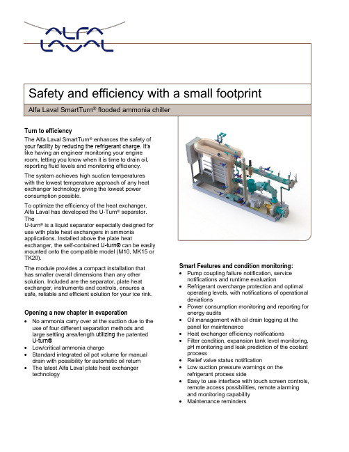
Alfa Laval SmartTurn® flooded ammonia chillerSafety and efficiency with a small footprintTurn to efficiencyThe Alfa Laval SmartTurn® enhances the safety ofyour facility by reducing the refrigerant charge. It’slike having an engineer monitoring your engineroom, letting you know when it is time to drain oil,reporting fluid levels and monitoring efficiency.The system achieves high suction temperatureswith the lowest temperature approach of any heatexchanger technology giving the lowest powerconsumption possible.To optimize the efficiency of the heat exchanger,Alfa Laval has developed the U-Turn® separator.TheU-turn® is a liquid separator especially designed foruse with plate heat exchangers in ammoniaapplications. Installed above the plate heatexchanger, the self-contained U-turn® can be easilymounted onto the compatible model (M10, MK15 orTK20).The module provides a compact installation that has smaller overall dimensions than any other solution. Included are the separator, plate heat exchanger, instruments and controls, ensures a safe, reliable and efficient solution for your ice rink. Opening a new chapter in evaporation•No ammonia carry over at the suction due to the use of four different separation methods andlarge settling area/length utilizing the patentedU-turn®•Low/critical ammonia charge•Standard integrated oil pot volume for manual drain with possibility for automatic oil return •The latest Alfa Laval plate heat exchanger technology Smart Features and condition monitoring: •Pump coupling failure notification, service notifications and runtime evaluation •Refrigerant overcharge protection and optimal operating levels, with notifications of operational deviations•Power consumption monitoring and reporting for energy audits•Oil management with oil drain logging at the panel for maintenance•Heat exchanger efficiency notifications•Filter condition, expansion tank level monitoring, pH monitoring and leak prediction of the coolant process•Relief valve status notification•Low suction pressure warnings on therefrigerant process side•Easy to use interface with touch screen controls, remote access possibilities, remote alarmingand monitoring capability•Maintenance remindersAlfa Laval reserves the right to change specification without prior notificationHow to find out more information on SmartTurn ®Visit our websiteat www.alfalaval.ca/smartturnHow to contact Alfa Laval Up-to-date Alfa Laval contact details for all countries are always available on our website at www.alfalaval.c aCA ED GHE0001 1710The U Turn and the Plate Heat Exchanger – the heart of the SmartTurn ®Capacity, Dimensions and weightsSystemLength Width Height Shipping weight(Approx.) 80TR Ethylene Glycol* 162 ¾ ″ / 4134 mm 39 ½ ″ / 1003 mm 86 ⅜ ″ / 2194 mm 5000 lbs / 2268 kg 100TR Ethylene Glycol* 186 ½ ″ / 4737 mm 49 ″ / 1245 mm 112 ″ / 2845 mm 5000 lbs / 2268 kg 120TR Ethylene Glycol* 189 ½ ″ / 4813 mm 49 ″ / 1245 mm 111 ¾ ″ / 2838 mm 5000 lbs / 2268 kg 80TR Brine* 162 ¾ ″ / 4134 mm 39 ½ ″ 1003 mm 86 ⅜ ″ / 2194 mm 5000 lbs / 2268 kg 100TR Brine* 180 ¾ ″ / 4591 mm 51 ″ / 1295 mm 106 ¾ ″ / 2711 mm 5000 lbs / 2268 kg 120TR Brine*184 ¾ ″ / 4693 mm51 ″ / 1295 mm106 ¾ ″ / 2711 mm5000 lbs / 2268 kg*Based on standard conditions with 18°F (-7.8°C) in, 15°F (-9.4°C) out with evaporation temperature of 11°F (-11.6°C)。
循环冷却器使用说明书

循环冷却器使用说明书全文共四篇示例,供读者参考第一篇示例:循环冷却器使用说明书一、概述循环冷却器是一种常用的设备,用于降低工业和商业过程中产生的热量。
它通过传热介质循环流动,将热量从系统中移除,从而起到降温的作用。
本说明书将介绍循环冷却器的操作方法、注意事项以及常见故障排除方法,帮助用户更好地使用和维护设备。
二、操作方法1. 接通电源:首先要确保循环冷却器已经连接好电源并接通,确认电路正常。
2. 调节温度:根据实际需要,调节循环冷却器的工作温度,通常可以通过设备上的调节盘或数字控制面板进行设置。
3. 添加冷却介质:在循环冷却器的储冷槽中加入足够的冷却介质,注意不要过多或过少,以免影响设备的工作效果。
4. 启动设备:按下启动按钮,循环冷却器将开始工作。
在启动过程中,注意观察设备运行情况,确保正常运转。
5. 观察冷却效果:在设备工作一段时间后,可以通过观察被冷却物体的温度变化来评估设备的冷却效果,以便及时调整参数。
6. 关闭设备:当不需要使用循环冷却器时,按下停止按钮,将设备停止工作并断开电源。
三、注意事项1. 定期清洁:定期清洁冷却器内部和外部,避免灰尘和污垢堵塞散热器和管道,影响设备的散热效果。
2. 避免过载:避免长时间超负荷运行循环冷却器,以免损坏设备或影响其使用寿命。
3. 注重安全:操作设备时要注意安全,避免触电、烫伤等事故的发生。
在维护设备时,应断开电源并等待设备冷却后再进行操作。
4. 储存保养:当长时间不使用循环冷却器时,应将冷却介质清空,清洁设备并储存在干燥通风处,以免生锈或发霉。
四、常见故障排除方法1. 设备无法启动:检查电源是否接通,电路是否连接正常,启动按钮是否损坏,并及时更换损坏的部件。
2. 冷却效果不佳:检查冷却介质是否足够,设备是否清洁,管道是否堵塞,如果有问题及时清洁或更换部件。
3. 噪音过大:检查设备支撑是否牢固,运行过程中是否有异物进入导致噪音,及时清除问题。
4. 温度波动大:检查设备温度传感器是否损坏,导致温度显示不准确,及时更换故障部件。
西方空调水冷却器SIGMA技术说明书
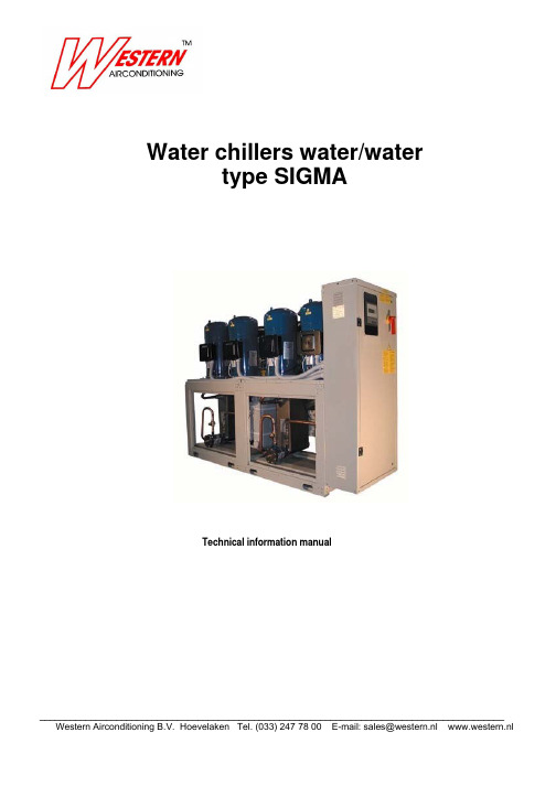
Water chillers water/watertype SIGMATechnical information manual___________________________________________________________________________________________Technical information manual SIGMAREF.SIGMA-10230000012_04.08/SIGMA_2011.DOC INDEXTechnical features 1Versions 3Accessory versions 4data7Technical11dataElectricalCooling capacity 12Heating capacity 18Total heat recovery capacity 2526dataTechnical30ElectricaldataCooling capacity 31Heating capacity 37Total heat recovery capacity 45Fouling factor corrections 46Ethylene glycol mixtures 47Low temperatures corrections factors 4849levelsSoundsOperating limits 51Condenser pressure drop 52Evaporator pressure drop 54Dimensions, weights and55connectionshydraulicInstallation recommendations 68Technical information manual SIGMAREF.SIGMA-10230000012_04.08/SIGMA_2011.DOCTECHNICAL FEATURESSIGMA 2002 - Water chillersSTRUCTURESelf supporting frame, constructed in galvanized sheet steel with RAL 7032 powder paint baked at 180°C to provide a durable weatherproof finish. Models 3.2 to 7.2 and model 14.4 are completely enclosed by painted steel panels fully lined with a sound absorbing material. On models 8.2 to 13.2 only the upper compartment, which contains the compressors, is fully enclosed on all sides by painted steel panels fully lined with a sound absorbing material. On models 8.2 to 13.2 only the upper compartment , which contains the compressors, and the separator between this compartment and the lower part of the unit are enclosed by painted steel panels fully lined with a sound absorbing material. Models 16.4 to 26.4 do not have panels.COMPRESSORSHermetic scroll type with orbital motion, connected in tandem and equipped with oil level sight glass, Klixon internal thermal protection and oil equalisation line.EVAPORATOR AND CONDENSERBrazed plate type in 316 AISI stainless steel. Thermal insulation of evaporator is provided by closed cell expanded material. Each evaporator is equipped with a low water temperature probe for freeze protection and each unit is equipped as standard with a mechanical flow switch.REFRIGERANT CIRCUITComprising: liquid valve, charge connection, liquid sight-glass, filter/dryer, thermostatic expansion valve with external pressure equalisation, high and low pressure switches for 2-compressor models. For 4-compressor models high and low pressure values and relative condensation and evaporation temperatures are measured by pressure transducers that relay the signals to the controller so that they can be read directly on the display. The high pressure side of the circuit is equipped with high pressure switches and relief valves.Technical information manual SIGMAREF.SIGMA-10230000012_04.08/SIGMA_2011.DOCELECTRICAL PANELThe electrical panel includes:- main switch- fuses for the auxiliary and power circuit- compressor contactors- microprocessor mCHILLER for 2 compressor units and PCO² for 4 compressors units,controlling the following functions:- water temperature regulation- freeze protection- compressor time intervals- compressor start sequence and automatic lead/lag selection- alarm reset- common alarm contact for remote signalling- operating and alarm indicator LEDs- LCD display of the following information:- water inlet and outlet temperature- programmed temperature set-point and differential- alarms description- compressor hours run meter for units with PCO² control- number of starts of the unit and the compressors- high and low pressure values and relative condensation and evaporation temperature valuesElectrical power supply [V/f/Hz]: 400/3~/50 ±5%CONTROLS AND SAFETY DEVICES- High pressure switch with manual reset- High pressure safety, with manual reset, controlled by the unit controller on four compressors models- Low pressure safety switch, with manual reset, controlled by the unit controller for four compressor models,low pressure switch, with manual reset, controlled by the unit microprocessor for the two compressors models- High pressure relief valve- Chilled water temperature sensor (at the evaporator inlet); on four compressors model it is installed on one evaporator only.- Freeze protection sensor at the outlet of each evaporator- Mechanical flow switch supplied as standard as kit with the unit- Compressor over-temperature protectionTESTINGThe units are subjected to a dry run in the factory and supplied complete with oil and refrigerant.Technical information manual SIGMAREF.SIGMA-10230000012_04.08/SIGMA_2011.DOCSIGMA UNIT VERSIONSSIGMA 2002/HP: reverse cycle heat pumpThe heat pump version operates as a water cooled chiller in summer and a water to water heat pump in winter by reversing the refrigerant flow to suit the required operating mode. In addition to the components of version SIGMA 2002, the heat pump version includes:REFRIGERANT CIRCUIT:4-way reversing valve and a second thermostatic expansion valve.ELECTRICAL PANEL:Microprocessor programmed for summer/winter changeover (the Macroplus microprocessor is used on 4 compressor HP units).SIGMA 2002/LE: motorcondensing unitThe unit is designed to operate with a remotely located refrigerant to air evaporator. It is supplied without a refrigerant to water evaporator and thermostatic expansion valve. The solenoid valve on the liquid line is supplied as standard. Models 3.2 to 13.2 have mchiller control and the remainder of the range is supplied without control. The standard supply is ON/OFF for each compressor from a digital entry.SIGMA 2002/LE/HP: motorcondensing unitThe unit is designed to operate with a remotely located refrigerant to air evaporator. It is supplied without a refrigerant to water evaporator and thermostatic expansion valve. The solenoid valve on the liquid line and liquid receivers are supplied as standard. Models 3.2 to 13.2 have mCHILLER control and the remainder of the range is supplied without control. The standard supply is ON/OFF for each compressor from a digital entry.SIGMA 2002/LC: motorevaporating unitThe unit is supplied without a water cooled condenser and is designed to be connected to a remotely located air cooled condenser.SIGMA 2002/LC/HP: motoevaporating unitThe unit is supplied without a water cooled condenser and is designed to be connected to a remotely located air cooled condenser. The solenoid valve on the liquid line and the liquid receivers are supplied as standard ACCESSORY VERSIONSSIGMA 2002/DC: unit with heat recovery condenserNot available for HP versions. In addition to the components of version SIGMA 2002 this unit includes a 100% heat recovery condenser, for the production of hot water, and a liquid receiver on each refrigerant circuit.SIGMA 2002/DS: unit with desuperheatersAvailable for all models. A brazed plate type heat recovery exchanger (desuperheater) is arranged in series with the condenser. Also available on all HP models. In this case an isolating valve must be fitted on the water recovery circuit and be closed during heat pump mode operation as described in the manual.SIGMA LN: low noise unitLow noise units units are completely enclosed with painted steel panels lined with sound absorption material having an intermediate layer of high acoustic impedance material.Technical information manual SIGMAREF.SIGMA-10230000012_04.08/SIGMA_2011.DOCREFRIGERANT CIRCUIT ACCESSORIES- Compressor suction and discharge valvesBall valve fitted in the equalisation line- Pressostatic valve (with solenoid valve on heat pump)- Liquid line solenoid valve- Pressure gaugesOn all units with a PCO2 controller the suction and discharge pressures are displayed on the controller. Gauges on standard units are located inside the compressor compartment.- Liquid receivers (standard on versions /LE/HP and LC/HP LC/DC and DC)- Dual set-pointWith double thermostatic expansion valves and solenoid valves, the evaporator of “double set point units” is sized on the basis of high temperature operation. On units with mCHILLER control, the set must be manually modified on the microprocessor control panel. On units with PCO2 control the two values can be set from the keypad or via a digital input. In all cases the commutation between the two thermostatic expansion valves is automatic on the basis of the water temperature. Thermostatic expansion valve selection is made according to the temperature values specified at the the temperature values specified at the time of order. The operating limits remain unchanged and are as per the catalogue. If glycol is used, in a sufficient percentage to avoid freezing, the lower limit of the leaving water is extended to a minimum of -5 °C.- Condenser for well water (only standard version and LE).HYDRAULIC CIRCUIT ACCESSORIES- Leaving water temperature controlAvailable only on units with control PCO2 (not HP versions).- Water manifold(only 4 compressors models). Available for condensers, evaporators and heat recovery.ELECTRICAL ACCESSORIES- Power factor correction cos Ø0.9 at nominal operating conditions- Single voltage-free contacts for machine status signals- Serial interface.In units with a mCHILLER controller (3.2-13.2) the serial interface is the RS485 type with a Carel protocol. In units with a PC02 control (from 14.4-26.4 excluding HP versions) the serial interface is the RS485 type with a Modbus protocol. Special protocols can be ordered: Carel; Echelon in RS485 or FTT10 versions. HP units can be supplied with a Macroplus microprocessor controller with a RS422 type serial interface; refer to the manual enclosed with the unit.- Remote user terminal panel(in addition to the standard terminal) Not available on HP units (with a Macroplus controller)- Set point variable with remote signal(0-1V, 0-10V, 0-4mA, 0-20mA) available only on units with a PC02 controller, only in cooling mode. At the time of order. The set point values must be specified at the time of order.Technical information manual SIGMAREF.SIGMA-10230000012_04.08/SIGMA_2011.DOCVARIOUS ACCESSORIES- Rubber antivibration mountings- Timber crate packing- Pallet/skid for shipment in a container- Non-standard RAL paint colours- Unit completely pre-assembled, the unit will be supplied without refrigerant charge, test and PED certificate - Modular pre-asembled unit, only 4 compressors models, with the exception of model 14.4.Technical information manual SIGMA REF.SIGMA-10230000012_04.08/SIGMA_2011.DOCTECHNICAL DATA(*) Evaporator entering/leaving temperature 12-7 °C; Condenser entering/leaving temperature 30-35 °C (**) Condenser entering/leaving temperature 40-45 °C; Evaporator entering/leaving temperature 15-10 °C.Technical information manual SIGMA REF.SIGMA-10230000012_04.08/SIGMA_2011.DOCTECHNICAL DATA(*) Evaporator entering/leaving temperature 12-7 °C; Condenser entering/leaving temperature 30-35 °C (**) Condenser entering/leaving temperature 40-45 °C; Evaporator entering/leaving temperature 15-10 °C.Technical information manual SIGMA REF.SIGMA-10230000012_04.08/SIGMA_2011.DOCTECHNICAL DATA(*) Evaporator entering/leaving temperature 12-7 °C; Condenser entering/leaving temperature 30-35 °C (**) Condenser entering/leaving temperature 40-45 °C; Evaporator entering/leaving temperature 15-10 °C.Technical information manual SIGMAREF.SIGMA-10230000012_04.08/SIGMA_2011.DOCTECHNICAL DATA(*) Evaporator entering/leaving temperature 12-7 °C;Condenser entering/leaving temperature 30-35 °C(**) Condenser entering/leaving temperature 40-45 °C;Evaporator entering/leaving temperature 15-10 °C.Technical information manual SIGMAREF.SIGMA-10230000012_04.08/SIGMA_2011.DOCELECTRICAL CHARACTERISTICS(1) Mains power supply to allow unit operation(2) Maximum current before safety cut-outs stop the unit. This value is never exceeded and must be used to size theelectrical supply cables and relevant safety devices (refer to electrical wiring diagram supplied with the unit).Technical information manual SIGMAREF.SIGMA-10230000012_04.08/SIGMA_2011.DOCCOOLING CAPACITYkWf : cooling capacity [kW]kWe : compressors power input [kW]kWe : total recovery heating capacity [kW]T0 : evaporator leaving water temperature [°C]Inlet/outlet evaporator water thermal difference 5°CTechnical information manual SIGMAREF.SIGMA-10230000012_04.08/SIGMA_2011.DOCCOOLING CAPACITYkWf : cooling capacity [kW]kWe : compressors power input [kW]kWe : total recovery heating capacity [kW]T0 : evaporator leaving water temperature [°C]Inlet/outlet evaporator water thermal difference 5°CTechnical information manual SIGMAREF.SIGMA-10230000012_04.08/SIGMA_2011.DOCCOOLING CAPACITY SIGMA 2002 /LEkWf : cooling capacity [kW]kWe : compressors power input [kW]Tev : total recovery heating capacity [kW]Inlet/outlet evaporator water thermal difference 5°CTechnical information manual SIGMAREF.SIGMA-10230000012_04.08/SIGMA_2011.DOCCOOLING CAPACITY SIGMA 2002 /LEkWf : cooling capacity [kW]kWe : compressors power input [kW]Tev : total recovery heating capacity [kW]Inlet/outlet evaporator water thermal difference 5°CTechnical information manual SIGMAREF.SIGMA-10230000012_04.08/SIGMA_2011.DOCCOOLING CAPACITY - SIGMA 2002/LCkWf : cooling capacity [kW]kWe : compressors power input [kW]kWe : total recovery heating capacity [kW]T0 : evaporator leaving water temperature [°C]Inlet/outlet evaporator water thermal difference 5°CTechnical information manual SIGMAREF.SIGMA-10230000012_04.08/SIGMA_2011.DOCCOOLING CAPACITY - SIGMA 2002/LCkWf : cooling capacity [kW]kWe : compressors power input [kW]kWe : total recovery heating capacity [kW]T0 : evaporator leaving water temperature [°C]Inlet/outlet evaporator water thermal difference 5°CTechnical information manual SIGMAREF.SIGMA-10230000012_04.08/SIGMA_2011.DOCHEATING CAPACITYKWt : heating capacity [kW]kWe : compressors power input [kW]T0 : evaporator inlet air temperature dry bulb [°C]Inlet/outlet evaporator water thermal difference 5°CTechnical information manual SIGMAREF.SIGMA-10230000012_04.08/SIGMA_2011.DOCHEATING CAPACITYKWt : heating capacity [kW]kWe : compressors power input [kW]T0 : evaporator inlet air temperature dry bulb [°C]Inlet/outlet evaporator water thermal difference 5°CTechnical information manual SIGMAREF.SIGMA-10230000012_04.08/SIGMA_2011.DOCHEATING CAPACITY SIGMA 2002 HP/LEKWt : heating capacity [kW]kWe : compressors power input [kW]T0 : evaporator inlet air temperature dry bulb [°C]Inlet/outlet evaporator water thermal difference 5°CTechnical information manual SIGMAREF.SIGMA-10230000012_04.08/SIGMA_2011.DOCHEATING CAPACITY SIGMA 2002 HP/LEKWt : heating capacity [kW]kWe : compressors power input [kW]T0 : evaporator inlet air temperature dry bulb [°C]Inlet/outlet evaporator water thermal difference 5°CTechnical information manual SIGMAREF.SIGMA-10230000012_04.08/SIGMA_2011.DOCHEATING CAPACITY SIGMA 2002 HP/LCKWt : heating capacity [kW]kWe : compressors power input [kW]Tev : total recovery heating capacity [kW]Inlet/outlet evaporator water thermal difference 5°CTechnical information manual SIGMAREF.SIGMA-10230000012_04.08/SIGMA_2011.DOCHEATING CAPACITY SIGMA 2002 HP/LCKWt : heating capacity [kW]kWe : compressors power input [kW]Tev : total recovery heating capacity [kW]Inlet/outlet evaporator water thermal difference 5°CTechnical information manual SIGMAREF.SIGMA-10230000012_04.08/SIGMA_2011.DOCHEATING CAPACITY SIGMA 2002 HP/LCKWt : heating capacity [kW]kWe : compressors power input [kW]Tev : total recovery heating capacity [kW]Inlet/outlet evaporator water thermal difference 5°CTechnical information manual SIGMAREF.SIGMA-10230000012_04.08/SIGMA_2011.DOCTOTAL HEAT RECOVERY CAPACITYkWf : cooling capacity [kW]kWe : compressors power input [kW]kWe : total recovery heating capacity [kW]T0 : evaporator leaving water temperature [°C]Inlet/outlet evaporator water thermal difference 5°CTechnical information manual SIGMAREF.SIGMA-10230000012_04.08/SIGMA_2011.DOC Inlet/outlet condenser water thermal difference 5°CTechnical information manual SIGMAREF.SIGMA-10230000012_04.08/SIGMA_2011.DOC FOULING FACTOR CORRECTIONSf1-f2 : capacity correction factorsfp1-fp2 : compressor power input correction factorUnit performances reported in the tables are given for the condition of clean exchanger (fouling factor = 1),For different fouling factor values, unit performances should be corrected with the correction factors shown above.Technical information manual SIGMA REF.SIGMA-10230000012_04.08/SIGMA_2011.DOCETHYLENE GLYCOL MIXTURESETHYLENE GLYCOL MIXTURESThe use of ethylene glycol mixtures is intended to prevent freezing in chiller heat exchangers. The use of low freezing point mixtures causes a modification in the main thermodynamic properties of the units. The major parameters affected by the use of glycol mixtures are the following:- cooling capacity- power input- mixture flow- pressure dropIn the table below are reported correction factors referred to the most common ethylene glycol mixtures. CALCULATION EXAMPLEAn example can help to use properly the coefficients reported in the table.Suppose that a water chiller SIGMA 282presents the following performances at the nominal working conditions:Technical information manual SIGMAREF.SIGMA-10230000012_04.08/SIGMA_2011.DOC LOW TEMPERATURES CORRECTIONS FACTORSTechnical information manual SIGMAREF.SIGMA-10230000012_04.08/SIGMA_2011.DOCSOUND LEVELSSTANDARD UNITLw: sound power levels in free field conditions calculated according to ISO 3746.Lp: sound pressure levels at 1 m from the unit in free field measured according to ISO 3746.THEORETICAL SOUND REDUCING VALUES WITH DISTANCE VARIATION IN FREE FIELDTechnical information manual SIGMAREF.SIGMA-10230000012_04.08/SIGMA_2011.DOCSOUND LEVELSLOW NOISE UNITLw: sound power levels in free field conditions calculated according to ISO 3746.Lp: sound pressure levels at 1 m from the unit in free field measured according to ISO 3746.THEORETICAL SOUND REDUCING VALUES WITH DISTANCE VARIATION IN FREE FIELDTechnical information manual SIGMAREF.SIGMA-10230000012_04.08/SIGMA_2011.DOC OPERATING LIMITSSIGMA 2002 - R407CThe water temperature rise for all versions must be between 4 °C (min) and 7 °C (max)(1) Working limits of units with 2 compressors(2) Working limits of units with glycol and water mixtureTechnical information manual SIGMAREF.SIGMA-10230000012_04.08/SIGMA_2011.DOC CONDENSER PRESSURE DROPThe water temperature rise for all versions must be between 4 °C (min) and 7 °C (max)Technical information manual SIGMAREF.SIGMA-10230000012_04.08/SIGMA_2011.DOC CONDENSER PRESSURE DROPThe water temperature rise for all versions must be between 4 °C (min) and 7 °C (max)Technical information manual SIGMAREF.SIGMA-10230000012_04.08/SIGMA_2011.DOC EVAPORATOR PRESSURE DROPThe water temperature rise for all versions must be between 3°C (min) and 8°C (max)Technical information manual SIGMAREF.SIGMA-10230000012_04.08/SIGMA_2011.DOC DIMENSIONS, WEIGHTS AND HYDRAULIC CONNECTIONS Sigma 2002 – model 3.2 – 7.2Technical information manual SIGMA REF.SIGMA-10230000012_04.08/SIGMA_2011.DOCDIMENSIONS, WEIGHTS AND HYDRAULIC CONNECTIONSSigma 2002 – model 3.2 – 7.2Technical information manual SIGMAREF.SIGMA-10230000012_04.08/SIGMA_2011.DOC DIMENSIONS, WEIGHTS AND HYDRAULIC CONNECTIONS Sigma 2002 – model 8.2 – 13.2Technical information manual SIGMA REF.SIGMA-10230000012_04.08/SIGMA_2011.DOCDIMENSIONS, WEIGHTS AND HYDRAULIC CONNECTIONS Sigma 2002 – model 8.2 – 13.2Technical information manual SIGMA REF.SIGMA-10230000012_04.08/SIGMA_2011.DOCDIMENSIONS, WEIGHTS AND HYDRAULIC CONNECTIONS Sigma 2002 – model 8.2 – 13.2Technical information manual SIGMAREF.SIGMA-10230000012_04.08/SIGMA_2011.DOC DIMENSIONS, WEIGHTS AND HYDRAULIC CONNECTIONS Sigma 2002 – model 14.4Technical information manual SIGMAREF.SIGMA-10230000012_04.08/SIGMA_2011.DOC DIMENSIONS, WEIGHTS AND HYDRAULIC CONNECTIONS Sigma 2002 – model 14.4Technical information manual SIGMAREF.SIGMA-10230000012_04.08/SIGMA_2011.DOC DIMENSIONS, WEIGHTS AND HYDRAULIC CONNECTIONS Sigma 2002 – model 16.4 – 26.4Technical information manual SIGMAREF.SIGMA-10230000012_04.08/SIGMA_2011.DOCDIMENSIONS, WEIGHTS AND HYDRAULIC CONNECTIONSSigma 2002 – model 16.4 – 26.4Technical information manual SIGMAREF.SIGMA-10230000012_04.08/SIGMA_2011.DOCDIMENSIONS, WEIGHTS AND HYDRAULIC CONNECTIONSSigma 2002 – model 16.4 – 26.4Technical information manual SIGMAREF.SIGMA-10230000012_04.08/SIGMA_2011.DOC DIMENSIONS, WEIGHTS AND HYDRAULIC CONNECTIONS SIGMA 2002/LC - SIGMA 2002/LC/HP - MODEL 8.2 – 13.2Technical information manual SIGMAREF.SIGMA-10230000012_04.08/SIGMA_2011.DOC DIMENSIONS, WEIGHTS AND HYDRAULIC CONNECTIONS SIGMA 2002/LC - SIGMA 2002/LC/HP - MODEL 8.2 – 13.2Technical information manual SIGMAREF.SIGMA-10230000012_04.08/SIGMA_2011.DOCINSTALLATION RECOMMENDATIONSLocation- Strictly allow clearances as indicated in the catalogue.- Locate the unit in order to be compatible with environmental requirements (sound level, integration into the site, etc.). Electrical connections- Check the wiring diagram enclosed with the unit, in which are always present all the instructions necessary to the electrical connections.- Supply the unit at least 12 hours before start-up, in order to turn crankcase heaters on. Do not disconnect electrical supply during temporary stop periods (i.e. weekends).- Before opening the main switch, stop the unit by acting on the suitable running switches or, if lacking, on the remote control.- Before servicing the inner components, disconnect electrical supply by opening the main switch.- The electric supply line must be equipped with an automatic circuit breaker (to be provided by the installer). Hydraulic connections- Carefully vent the system, with pump turned off, by acting on the vent valves. This procedure is fundamental:little air bubbles can freezfreeze the evaporator causing the general failure of the system.- Drain the system during seasonal stops (wintertime) or use proper mixtures with low freezing point. In case of temporary stop periods an electric heater should be installed on the evaporator and hydraulic circuit.- Install the hydraulic circuit including all the components indicated in the recommended hydraulic circuit diagrams (expansion vessel, flow switch, strainer, storage tank, vent valves, shut off valves, flexible connections, etc.).- Connect the flow switch, which is furnished on all units, not fitted. Follow the instructions enclosed with the units. Start up and maintenance operations- Strictly follow what reported in use and maintenance manual. All these operations must be carried on by trained personnel only.。
Thermo Scientific ThermoChill系列循环冷却器性能指南说明书

Thermo Scientific ThermoChill Series Recirculating ChillersPerformance, value, simplicityThe Ideal FitT emperature control products for a variey of applications As an innovative leader in temperature control, wehave the expertise to help enable you to optimizeyour liquid cooling and heating applications whileincreasing productivity and reducing operatingcosts. With over 50 years of service and countlesssuccessful installations around the world, we collaboratewith you to provide product and applications expertiseto meet the most demanding temperature controlrequirements. From bio-tech and pharmaceutical toprinting and semiconductor industries, companies aroundthe world continue to make Thermo Scientific temperaturecontrol products their ideal choice.Typical Applications:•Analytical •Automotive •Biotech •Laboratory•Laser•Packaging•Printing•Small Industrial•UniversitySelect the product that is right for your applicationfrom a comprehensive portfolio of temperature controlsolutions that deliver scalable product offerings rangingfrom bench top research to large process manufacturing.Our new and innovative products – developed fromcustomer feedback – represent a breakthrough inperformance, configurability and technology that providethe following advantages:A Flexible Choice: We have options to help you configurea flexible, cost-effective temperature control system thatsuits your specific requirements.Innovation: Our research and development team isfocused on designing innovative products based on yourfeedback.Global Service and Support: With our extensive globalfootprint, as well as, service and support capabilities, wecan support you anywhere in the world.Thermo Scientific ThermoChill recirculating chiller seriesPerformance: with your choice of cooling and pumping capacities, and a wide temperature range, select the performance level your application requires.Value: when you need reliable cooling support for your application, this powerful recirculating chiller offers ahigh quality, cost effective solution.Simplicity: innovative and intuitive controller that is easy to use, and a plug-and-play design that allows you to be up and running in minutes.Performance, value and simplicityCooling Lightilluminates when this chilleris cooling Setpointilluminates when setpoint isbeing adjusted Low Temp Alarm illuminates during adjustment or alarm High Temp Alarm illuminates during adjustment or alarmCommunications illuminates when serial communication is enabled(optional)Pressure Gauge for easy viewing of application pressureDigital Display indicates setpoint and displays additional operating values with menu selectionTouchpad Data Entry adjusts controller valuesEnter Button accesses menus and confirms settingsPower ButtonLocking casters for easy maneuveringAccessible fill port for easy fillingIntuitive digital controller with controllerindicator lights (see diagram below)RS232 digital communications optional(located on the back of the chiller)Pressure gauge located on control panelfor easy viewing of application pressurePerformance curvesCooling Capacity for ThermoChill I, II, & IIIPumping Capacity for Positive Displacement Pumps (PD-1 and PD-2)Pumping Capacity for Magnetically Driven Centrifugal Pump (MDC1)Cooling capacity based on chillers with PD-1 pumps with no backpressure. Other pumps will affect cooling capacity performance. Pressure values are differential pressures between the inlet and the outlet of the chiller. Specifications subject to change. C ooling capacity obtained using water between 8 °C to 30 °C and 50/50 Ethylene Glycol/water below 8 °C. Glycol water mixtures are required below 8 °C in order to prevent freezing of the cooling coils. Failure to follow these directions will result in a loss of cooling capacity and potential damage to the chiller.ACBTemperature ºC ºF4050607080-101030203050 HzA = ThermoChill IIIB = ThermoChill IIC = ThermoChill I20o C o l i n g C a p a c i t y800060004000200000BTU/Hr Watts 2500200015001000500AB A = PD-1B = PD-27.010*******60504030201006.05.04.03.02.01.0000123455101520P r e s s u r eBARPSIDFlow Rate LPM GPM50 HzAB CTemperatureo C o l i n g C a p a c i t y800060004000200000BTU/HrWatts 2500200015001000500ºC ºF4050607080-10100302060 Hz3020A = ThermoChill IIIB = ThermoChill IIC = ThermoChill IAB7.010090807060504030201006.05.04.03.02.01.00LPM GPM00123455101520P r e s s u r eBARPSIDFlow RateA = PD-1B = PD-260 Hz241.5050 Hz & 60 HzBARPSID LPM0 2.55.07.510.012.515.017.520.0GPM012345Flow RateP r e s s u r e1.251.000.750.500.252016128400Innovative designThe ThermoChill series of chillers is a compact line of refrigerated recirculators offering cooling capacities up to 2000 watts. Innovative design features such as minimized plumbing connections and an integrated full-flow fluid strainer maximize product reliability.Three Pump OptionsPositive Displacement Pumps (PD-1/PD-2) deliver a consistent flow over a wide pressure range making them appropriate for use with high back-pressure applications. Adding the external pressure reducer (EPR) accessory allows safe use with pressure sensitive applications.Magnetically Driven Centrifugal Pump (MDC1) deliver high flow rates at low pressure making them ideal for use with laboratory glassware and other low back-pressure applications.SpecificationsSpecifications obtained at sea level using water as the recirculating fluid, at a 20 °C process setpoint, 20 °C ambient condition, at nominal operating voltage. O ther fluids, process temperatures, ambient temperatures, altitude or operating voltages will affect performance.1 UL listing applies to 60 Hz ThermoChill models only.External Pressure Reducer (EPR) AccessoryThis accessory attaches to the chiller to limit the maximum outlet pressure of the chiller. Choose this accessory when circulating to applications that are sensitive to higher pressures or when circulating through glass.ThermoChill Plumbing KitThe plumbing includes (2) ½-in x ½-in MPT fittings, 25 feet of 5/8-in ID Polybraid hose, (2) hose clamps & hose insulation. The plumbing kit can be used across all ThermoChill models.Need More Capacity?The Thermo Scientific™ Polar, Thermo Scientific™ ThermoFlex™ , and Thermo Scientific™ Merlin™recirculating chillers have additional temperature ranges, cooling capacities, and pumping capacities available to meet your specific application requirements.Visit /tempcontrolselector for more information.Please see contact information below, if you need assistance selecting a chiller and to discuss your application.Ordering InformationFind out more at /tc© 2016 Thermo Fisher Scientific Inc. All rights reserved. All trademarks are the property of Thermo Fisher Scientific and its subsidiaries unless otherwise specified. BRTCTHERMOCHILL 1116Australia +61 39757 4300China +800 810 5118France +33 (0) 1 60 92 48 00Germany +49 (0) 721 4 09 44 44India +91 22 6716 2200Italy +39 02 95059 552Japan +81-3-6832-9270Netherlands +31 76 579 55 55New Zealand +64 9 980 6700Nordic/Baltic/CIS countries +358 10 329 2200Spain/Portugal +34 93 223 09 18UK/Ireland +44 870 609 9254USA/Canada toll free +1 (800) 258-0830USA +1 (603) 436-9444Countries not listed +49 6184 90 6000North America ***************************Europe ****************************China *************************India ******************************Japan ****************************。
FT-10A说明书

16 冷水机故障分析及排除方法
7
17 一体式冷却水循环机技术参数.......................................................................................................................................... 8
10.4 配置向导....................................................................................................................................................................3
1 使用须知
尊敬的客户: 感谢您选择了北京拓荆东日科技有限公司的产品! 为了方便您的使用,请仔细阅读说明书,并按照说明书的步骤进行操作。
2 规格说明
序号 1 2 3 4 5
规格参数 供电电源 控制电源 出水温度 测量精度 工作环境
规格说明 380V/AC±10% 50HZ 220V/AC±10% 50/60HZ -5~30℃ 0.1℃@25℃ -20℃~70℃,≤85%RH非凝露
3 面板示意图.............................................................................................................................................................................1
水冷说明书ORION中文

符号,是告知提醒警告、注意的内容。在图中或旁边有具体的注 意内容(左图是注意触电)的描述,表示该行为。
符号,是告知禁止行为的。在图中或旁边有具体的禁止内容(左 图是禁止拆解)的描述,表示该行为。
符号,是告知强制或指示行为的。在图中或旁边有具体的指示内 容(左图是请连接地线)的描述,表示该行为。
压送泵水回路(冷却水排放口及旁通阀)的全封闭运转是严格禁止的。全封闭运转的话,压 力会超过 1.2MPa,会使过滤损坏,而且由于泵的故障及泵体发热,会导致配管变形和水的泄 露。 3.对开关频繁低进行 ON/OFF 操作,有可能引发故障。停机之后再启动时,请经过 3 分钟以上 时间。在 3 分钟以内启动运转的话,安全装置起保护作用,还会导致压缩机故障。 4.泵的空运行也是严格禁止的。水槽内必须加水,在确认水位之后再实施运转。 5.排水之际,请将冻结放置模式 OFF。因为泵的空运转会导致故障。 6.水要经常保持清洁,每一个月进行一次水回路检查。必要时,情换水。 (请参照「冷凝器过滤清扫」) 7.对冷凝器过滤,每一个月清扫一次。 (请参照「冷凝器过滤清扫」)
接触到设备内部,会导致触电。
产品和机械室内,不要淋水。
而且不要用水洗,否则会导致触电或火灾等。
不要损坏或加工电源线
电源线上放置重物,或过热,或牵拉,或挤压,都会导致电源线损坏,从 而引发触电或火灾等。
异常是要停止运转,向销售店或专业人员咨询。
异常状态下继续运转,会导致触电或火灾等。
漏电断电器工作时,请向专业人员咨询。
7
等,导致水管或泵破损。 14.对机体外的水管,要采取防冻措施。作为防冻措施,加防冻罩等,要保证右侧的板能够拆
卸,旁通阀的可以操作和确认。
警告
在壳盖打开的状态,或拆下的状态,绝对不要运转。一旦接触到机械内部,就会导致受伤或 触电。 最开始使用时、经过长期放置时,或更换水的的时候,即使水槽溢满,水管内也会留有空气。 空气不排掉,运转冷却器的话,冷水不循环,使得冷却器冻结或破损,压送泵损坏。 在这些场合,首先要运转压送泵,让冷水在水管内充分循环,以排出空气。 水管内的空气的排放方法,请参照「水配管空气排放方法」。
水水冷却器使用说明

装箱单型号:LSS- -D 编号:下列产品、备件全部装箱无误装箱检验员: 年月日纯水冷却器型号LSS- -D出厂编号本机经试验合格,准予出厂检验部门:检验人员:检验日期:生产单位:西安海德信电气有限公司纯水冷却器使用说明书西安海德信电气有限公司目录一、概述 (2)二、型号说明 (2)三、结构 (3)四、技术参数 (5)五、使用 (6)六、维修保养…………………………………7-8一、概述LSS系列纯水冷却装置,主要应用于冷却式大功率硅整流和感应炉及中频炉等大电气设备配套作为冷却保护副机。
本装置采用纯水(去离子水)作为主冷却介质,主冷却水循环回路和副冷却管路,设有水流量、水温、水压可控。
当装置在恶劣条件下运行时,能稳定地向主机输出额定温度、压力、流量的纯水。
为了防止纯水受容器管道污染而导致水压下降,本机循环冷却系统采用ICr18Ni9Ti不锈钢及工程塑料制造。
二、型号说明`L S S □ D三、结构本装置由换热器组、泵组、管路、大水箱及电气控制等五部分组成。
结构原理图1所示。
纯水从负载吸热后进入大水箱,经工作水泵加压后,通过自动换向阀F2进入换热器中以间壁传热方式将所载热量传给副冷却水,冷却后的纯水经本机出水口和连接管道,输入主机冷却水道吸热后又进入大水箱,重新进入水泵加压,形成周而复始循环回路,从换热器吸热后的副冷却水泄出机外。
本机动力采用双泵组合设计,两泵互为工作或备用。
设计中采用自动切换电路和自动换向阀门单路输出。
工作泵万一发生故障,另一水泵自动起动工作,换向阀自动换向并发出信号,且能不停机对故障进线检修。
换向器组为单独的不锈钢板式换热器。
采用2台或3台换热器组一般为并联安装,可不停机对其中一台进行清洗或检修。
四、技术参数LSS-系列纯水冷却装置五、使用1、根据底脚安装尺寸的要求,将整机安装在预制的混你土基础上。
2、用经清洗洁净的耐腐蚀管道安装好主副机连续管道。
本机纯水进出口处出厂时各装上一只不锈钢法兰接管,安装时只需要将相同口径的不锈钢管焊接上就可,同时安装主机进出口阀门(可在主机调压和维修),安装好副冷却水外接管道并试压检漏,在副水进口处保证压力以及水质必须达到(技术参数表)范围之内。
Thermo Scientific NESLAB Merlin 循环冷却机产品说明书
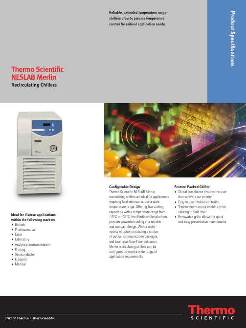
Configurable DesignThermo Scientific NESLAB Merlinrecirculating chillers are ideal for applications requiring heat removal across a wide temperature range. Offering five cooling capacities with a temperature range from -15°C to +35°C, the Merlin chiller platform provides powerful cooling in a reliable and compact design. With a wide variety of options including a choice of pumps, communication packages, and Low Level/Low Flow indicators Merlin recirculating chillers can be configured to meet a wide range of application requirements.Ideal for diverse applications within the following markets •Biotech•Pharmaceutical •Laser •Laboratory•Analytical instrumentation •Printing•Semiconductor •Industrial •MedicalFeature-Packed Chiller•Global compliance ensures the user that safety is our priority•Easy to use intuitive controller •Translucent reservoir enables quick viewing of fluid level•Removable grille allows for quick and easy preventative maintenanceReliable, extended temperature range chillers provide precise temperature control for critical application needs.Thermo Scientific NESLAB MerlinRecirculating ChillersInnovative Design Cooling CapacityOptions Options include:FeatureBenefitCommunication package •RS232 or RS485•Remote start/stop •Status relay•Remote sensor portProvides digital communication for remote operation, monitoring and data loggingLow level/low flow safety package Alerts the user when the reservoir level or fluid flow are too low, to ensure maximum up time NESLAB NEScom software Allows the user to easily program and automate the temperature control process from a PC system Plumbing package Provides tubing, insulation and connections to optimize the user’s application installationExternal temperature gauge Allows the user to monitor system operating temperature at any point in-line between the chiller and the application External pressure gauge Allows the user to monitor system pressure at any point in-line between the chiller and the application Air filter kitsProtects the user’s chiller from harsh environments and allows for easy cleaningDeionized water package Maintains a water resistivity level between 1 and 3 mOhm/cm 2for cooling applications requiring ultra pure water Fluid filtrationReduces particulates down to the selected micron level to protect the user’s application 5,10,25, 40 micron (full flow)Ethylene GlycolAllows circulation to temperature down to -15°C in a 50/50 mixture with waterFeatureBenefitRefrigeration system Environmentally friendly CFC-free refrigeration system for precise temperature control and optimum stability Reservoir isolation valves Eliminates reservoir overflow when pumping verticallyFluid reservoir Enables the user to easily view the liquid level and fluid condition at a glance Global compliance Ensures the user that safety is our priorityRemovable grilleAllows the user easy access to quickly clean the condenser to maximize chiller uptime Integrated fluid pressure relief Allows setting of fluid supply pressure to meet the user’s specific application requirements Easy access reservoir drain Allows fast and easy access to quickly change fluidsPressure gaugeAllows the user to ensure the recirculation system is operating within the application requirements Digital temperature controller Provides intuitive controller with an easy-to-view digital display for simple operation High/low temperature alarms Allows the user to configure the chiller operating parameters to protect valuable equipment Compact designMaximizes valuable floor spacetemperature setpointc o o l i n g c a p a c i t yBTU/Hr °C °FWatts25002000100015005002000400060008000-15+5+20+35+5+35+65+95C =M25 @ 50/60 HzB =M33 @ 50/60 Hz A =M75 @ 50/60 Hz Fluid 50/50 EG/WaterAB C Cooling Capacity for NESLAB Merlin Recirculating Chillerstemperature setpointc o o l i n g c a p a c i t yBTU/Hr ABC D°C °FWatts20001000400080005000400030001200016000600020000-15+5+20+35+5+35+65+95D =M100 @50HzC =M100 @60Hz B =M150@50 Hz A =M150@60 Hz Fluid 50/50 EG/WaterCooling Capacity for NESLAB Merlin Recirculating ChillersCooling capacity based on a 50/50 ethylene glycol/water mixture. Cooling capacity based on units with PD1 pumps (M25, M33, & M75) and PD2 pumps (M100 & M150) with no backpressure. Other pumps will affect cooling capacity performance.Thermo Scientific NESLAB Merlin Recirculating ChillersNESLAB Merlin M25NESLAB Merlin M33NESLAB Merlin M75NESLAB Merlin M100NESLAB Merlin M150/tcprocessDSTCMerlinFam0509©2009 Thermo Fisher Scientific Inc. All rights reserved. All trademarks are the property of Thermo Fisher Scientific Inc. and its subsidiaries. Results may vary under different operating conditions. Specifications, terms and pricing are subject to change. Not all products are available in all countries. Please consult your local sales representative for details.For more information about Thermo Scientific NESLAB recirculating chillers, see our comprehensive range of temperature control equipment at /tcprocess.Thermo Fisher Scientific Inc. (NYSE: TMO) is the world leader in serving science, enabling our customers to make the world healthier, cleaner and safer. With annual revenues of $10.5 billion, we have approximately 34,000 employees and serve over 350,000 customers within pharmaceutical and biotech companies, hospitals and clinical diagnostic labs, universities, research institutions and government agencies, as well as environmental and industrial process control settings. Serving customers through two premier brands, Thermo Scientific and Fisher Scientific, we help solve analytical challenges from routine testing to complex research and discovery. The Thermo Scientific brand represents a complete range of high-end analytical instruments as well as laboratory equipment, software, services,consumables and reagents to enable integrated laboratory workflow solutions. Fisher Scientific provides a complete portfolio of laboratory equipment, chemicals, supplies and services used in healthcare, scientific research, safety and education. Together, we offer the most convenient purchasing options to customers and continuously advance our technologies to accelerate the pace of scientific discovery, enhance value for customers and fuel growth for shareholders and employees alike. Visit .North America: USA/Canada tollfree:+1 (800) 258-0830; USA:+1(603)*************************************Europe: Benelux:+31(0)**************************************;France:+33(0)**************************************;Germany:+49(0)***************************************;United Kingdom:+44(0)***************************************Asia: China:+86(21)****************************************;India:+91(22)*************************************。
水冷却器操作说明书_1
变压器油水冷却器相关产品操作维护说明1 综述变压器油是由变压器热量损失的热量来加热的。
变压器油直接进入冷却器外部的管束。
阻碍器是用来指引变压器油在交叉管中的流向的。
管子的冷却面被分为两部分甚至更多。
多数管路使用双回路水。
单管冷却器的特征非常必要使用单管冷却器使油压始终超过运转过程中的水压。
这样就防止了了水穿透油发生渗漏。
双管冷却器的特征不像变压器油水冷却器单管设计那样,管路为双管和双向管板。
这种特殊的安全设计能够在运转过程中避免冷却水压不再受油压的限制(通常小于2BAR)。
双管路冷凝器的标准设计适合水压在10BAR。
万一发生水或油的泄漏,他们将直接进入位于双管之间的小细管中,进入两管板中间的空间。
因此,双管系统的设计就避免了油水或水油的混合。
这种设计是对变压器和冷却水的保护。
发现泄漏后,冷却器的泄漏通路将和一个小的收集盒连接,以来控制泄漏,―这就是泄漏控制器。
在泄漏控制器部,有一个磁控浮动转换装置与收集传导器连接,即便发生几个立方厘米的泄漏也会及时报警。
2型号变压器油水冷却器的型号标注为字母WK例如:W K D H 250 DIN ZD---代表冷却器制造方式D-双管路设计E-单管路设计H---装配方向H-挂式L-卧式S-立式250-功率水平:40,63, 100,160, 250, 315,400, 500, 630…)DIN---型号系列比如DIN或EX, NR…Z---选择,与标准设计不同的设计3,安装变压器油水冷却器的输出是由密封油-油面的入出口有珐琅。
油仓充满含水量小于10%的氮气且压力为0.45BAR以便防止冷却器受侵蚀及受污。
在装卸时,封闭板必须拆除。
水冷却器必须安装在干燥的房间,且该房间不会受震动或相关干扰。
!!!注意:在启动热交换器前必须要经过检查确认。
3,1安装地点变压器油水冷却器必须安装在足够的空间里以便其能安全的工作运转。
变压器油水冷却器通常是由可抽取式的管束装配成的,因此,在交换器前的必要的清除是允许的。
养殖场实验室循环水冷却器操作指导书

养殖场实验室循环水冷却器操作指导书
1、水泵排空:使用前需要对泵室内进行室内空气排空:连
接水管后打开水箱盖加满水,打开排水口至有水排除后关闭排水口,水泵排空完毕!
2、开机:接通电源开关,显示窗全部点亮,月3s后进入到
正常显示状态。
3、开机压缩机延时:控制器通电1分钟后压缩机启动,同
时“C”符号点亮,,在压缩机启动之前,控制器不能进行温度控制。
4、温度的参看与设定:点击“SET”键,进入到温度设定状
态,显示窗上排显示提示符“SP”,下排显示温度设定值,可通过SHIFT、DEC、INC键修改到所需的设定值,再点击“SET”
键,退出此设定状态,设定值将自动保存。
5、温度报警:当温度低于-10℃,和高于40℃时,报警,报
警指示灯亮,蜂鸣器鸣叫,显示屏显示报警代码(低温报警显示L-A;高温报警显示H-A),压缩机停止工作。
当出现温度报警后,必须关闭电源重新启动才能正常运行!
6、低水位报警:当控制器检测到水位低于限值时报警指示
灯,水位指示灯点亮,蜂鸣器鸣叫,系统将关闭压缩机和电磁阀,有水恢复时,压缩机要延时1分钟通电后,进入到正常运行状态。
7、蜂鸣器鸣叫时可按任意键消音。
注意:在设定状态下若1分钟之内无任何键按下,控制器会自动返回到正常状态。
YB-LS风冷式冷却循环水机说明书

YB-LS系列风冷式冷却循环水机使用说明书上海亿倍实业有限公司前言感谢您购买上海亿倍公司的YB-LS系列冷却循环水机,在您使用前请阅读和理解本说明书中的各项内容,以便正确使用。
不正确的使用,将造成不正常的运行或引起故障和降低使用寿命。
在安装,水路,通电,运行,维护检查前,必须熟悉说明书内容,以保证正确使用。
使有时,即使对“注意”类说明的事项,如不遵守,根据情况,也有可能发生严重后果。
所以本书阐述的重要内容都必须遵守为要。
有关用途有关安装1 使用前有关事项1-1 到货检查收到您订购的设备后,请开箱检查以下各项,如发现产品有问题或不符合您订购的规格,请与您代理商或我公司联系。
(1)核对冷却循环水机上的铭牌,确认您订购的规格。
型号(TYPE):冷却循环水机型号特征代号,用英文字母表示型号代号,用数字表示产品代号上海亿倍标识注:特征代号:英文大写字母A表示一体机;(无为默认一体机)英文大写字母B表示空调式分体机;英文大写字母C表示组装机组式分体机。
电源定额值(SOURCE):冷却循环水机输入电源额定值重量(MASS):冷却循环水机的净重量(2)外观检查有无任何运输过程中发生的损坏,如外壳和机身的弯折,另的部件损坏或脱落等。
(3)除冷却循环水机本身和使用说明书外,是否有您与代理商订购的附件等。
2 安装与连接2-2安装说明:( 1)机组安装:室外机组的安装应稳定,牢固。
室外机组高度应低于室内机组,室内机组应靠近室外机组一侧,以尽量减少管路长度、降低制冷效率的损耗。
(2)水路安装:应注意主机的出水管应接在室内机组的入水口;主机的进水管应接在室内机组的出水口。
(3)电源:机组采用单相三线220V±10%交流电源,注意安装保护地线。
(4)注水:打开水箱上盖,注入纯水或蒸馏水,注水高度应距水箱上沿10mm。
水泵严禁空载使用。
2-3 打开本冷却循环水机,应见各接线端子,接线时千万不要接错线。
(只有大功率冷却循环水机才有电源线连接)(1)电源一定要连接于主电源端子。
JULABO AWC100 空气 水循环冷却器说明书
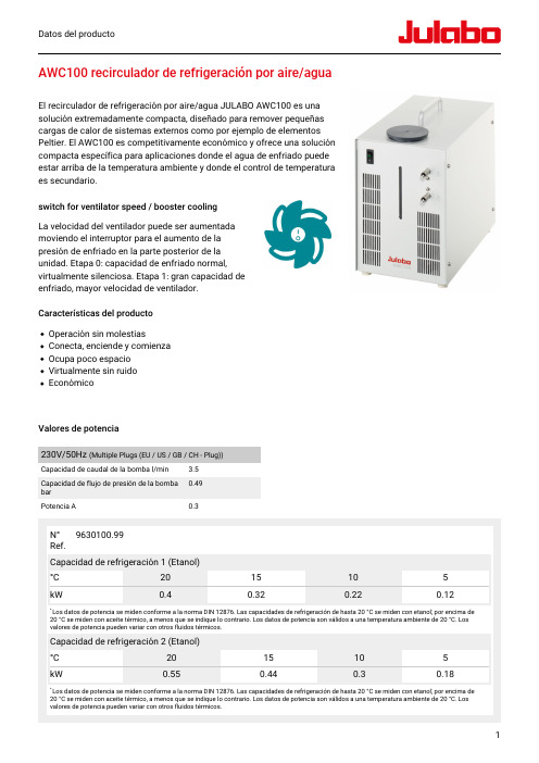
Datos del producto1AWC100 recirculador de refrigeración por aire/aguaEl recirculador de refrigeración por aire/agua JULABO AWC100 es una solución extremadamente compacta, diseñado para remover pequeñas cargas de calor de sistemas externos como por ejemplo de elementos Peltier. El AWC100 es competitivamente económico y ofrece una solución compacta específica para aplicaciones donde el agua de enfriado puede estar arriba de la temperatura ambiente y donde el control de temperatura es secundario.switch for ventilator speed / booster cooling La velocidad del ventilador puede ser aumentada moviendo el interruptor para el aumento de la presión de enfriado en la parte posterior de la unidad. Etapa 0: capacidad de enfriado normal,virtualmente silenciosa. Etapa 1: gran capacidad deenfriado, mayor velocidad de ventilador.Características del producto Operación sin molestiasConecta, enciende y comienza Ocupa poco espacio Virtualmente sin ruidoEconómicoValores de potencia230V/50Hz (Multiple Plugs (EU / US / GB / CH - Plug))Capacidad de caudal de la bomba l/min 3.5Capacidad de flujo de presión de la bomba bar 0.49Potencia A0.3Datos del producto - AWC100Refer to for more information regarding the entire JULABO product portfolio. Technical changes without prior notification. Images may deviate from the original. | Datasheet No.ES9.630.100/2208162Información técnicaVersiones de tensión disponiblesN° Ref.9 630 100Versiones de tensión disponibles:9630100.99100-230V/50-60Hz (Multiple Plugs (EU /US / GB / CH - Plug))RefrigeraciónRefrigeración de la máquina de enfriamiento AireOtrosNivel de presión de sonido dbA 55Clasificación IP IP 21Tipo de bombaBomba centrífugaTamaños y volúmenesPeso kg9.7Diámetro interior de los conectores de manguera8/10 mm Dimensiones cm (W x L x H)20 x 34 x 30Volumen de llenado l 0.9Conexiones de bombaM10x1Valores de temperaturaRango de temperatura de operación °C +20 ... +40Temperatura ambiente admisible °C+5 ... +35Incluido en la entrega2 adaptadores dentados apropiados para tubería de 8 y 10 mm de diámetro interior. (conexiones de bomba M10x1 hembra)BeneficiosComprobado al 100%100% de pruebas. 100% de calidad. Cadatermostatos de circulación JULABO es sometido a extensas pruebas de calidad antes de salir de lafábrica.Tecnología ambiental.Desarrollo y aplicación constante de materialesecológicos y tecnólogia ambiental.Calidad JULABOLos más altos estándares de calidad para unalarga vida del producto.Rápida puesta en marcha.Se encuentran a su disposición manuales de usuario y consultas individuales por parte deJULABO.Clientes satisfechos.Las 11 subsidiarias y más de 100 socios en todo elmundo garantizan un soporte rápido y calificado.Servicio las 24h.Disponibilidad en todo momento. Puede encontrar los accesorios adecuados, estudios de casos,manueles y mucho más ingresando al sitio web .。
- 1、下载文档前请自行甄别文档内容的完整性,平台不提供额外的编辑、内容补充、找答案等附加服务。
- 2、"仅部分预览"的文档,不可在线预览部分如存在完整性等问题,可反馈申请退款(可完整预览的文档不适用该条件!)。
- 3、如文档侵犯您的权益,请联系客服反馈,我们会尽快为您处理(人工客服工作时间:9:00-18:30)。
deretsigeRnU目 录第一章 注意事项........................................................................................................................3 第二章 产品的安装 (4)2.1 放置场所......................................................................................................................4 2.2 水路要求......................................................................................................................4 2.3 冷却液要求...................................................................................................................4 2.4 压力调节......................................................................................................................5 2.5 设备的开停...................................................................................................................5 2.6 分体系列的安装...........................................................................................................5 第三章 产品的操作 (7)3.1 H35/H50/H130产品操作 (7)3.1.1 产品概述............................................................................................................7 3.1.2温度设置 (8)3.2 SMART SH150系列产品操作 (10)3.2.1 产品概述..........................................................................................................10 3.2.2温度设置..........................................................................................................13 3.3 H500/H700/H900产品操作 (15)3.3.1 产品概述..........................................................................................................15 3.3.2 温度设置..........................................................................................................17 3.3.3 报警提示..........................................................................................................17 3.4 KF500/700/1200产品操作 (18)3.4.1 产品概述 (18)3.4.2 温度设置..........................................................................................................19 3.4.3 报警提示..........................................................................................................20 3.5 HF500/700/900产品操作............................................................................................21 3.5.1 产品概述..........................................................................................................21 3.5.2温度设置..........................................................................................................23 3.5.3 报警提示..........................................................................................................23 3.6 TF600/800产品操作 (24)3.6.1 产品概述..........................................................................................................24 3.6.2 温度设置. (26)3.7 RH25-6A/12A 产品操作 (28)3.7.1产品概述..........................................................................................................28 3.7.2 温度设置. (30)第四章 产品的维护...................................................................................................................32 第五章 常见故障的排除...........................................................................................................33 第六章 售后服务. (34)Un Re gi st er ed第一章 注意事项敬告:在安装及使用本设备前,必须仔细阅读并理解本手册内容。
如有疑问,请与我公司 客户服务部联系。
1、禁止把设备放在温度过高,湿度过大的地方,禁止把设备与腐蚀性物质放在一起;2、设备内置的地线装置提供了电击保护,所以用户所提供的电源中要有相应的地线,用户有责任对此加以确认;3、禁止把设备的出水口和进水口与自来水相连,或把它们连接在其它水源上;4、禁止在本设备中使用可燃和腐蚀性液体;5、不要在本设备中使用汽车防冻液,商用的汽车防冻液中含有硅酸盐成份,容易损坏泵的密封圈。
如果是因为使用汽车防冻液而引起的设备损坏,将不在保修范围内;6、搬运时应轻抬轻放,倾斜不要超过60度,否则会损坏制冷系统;7、注意设备中所有的标签位置,不要撕毁它们;8、禁止操作已损坏或有泄漏的设备;9、禁止在水箱中无水时操作设备; 10、禁止使用已损坏的电源线;11、在对本设备进行任何保养、维护或搬运时,一定要切断电源并取下电源线;12、保养和维修前最好咨询本公司的技术人员,因为错误的操作会引起设备损坏。
如果因错误操作而引起的设备损坏,将不在保修范围之列。
13、禁止将室内机在室外使用,若在有雨水之处使用,则易发生触电事故;(适用分体系列)14、禁止把室内机放置在湿度过大或易淋到水的的场所,这会降低绝缘性,从而引起触电事故;(适用分体系列)15、使用专用独立的电源插座,如果电源线容量不足,易造成事故;良好地进行地线设置,如果接地不良,可能造成触电;(适用分体系列)Un Re gi st er ed第二章 产品的安装切记:1、第一次使用本设备时,请冲洗水箱及水路,最后一定要向水箱加满水。
待设备开启运 行后由于水箱水会进入管路,使水箱水变少,所以需要在水箱再添加水。
2、在关机后不要立即重新启动,应等待30秒钟后才允许启动3、如果设备需要更换到别的被冷却设备时,一定要注意,在拔下水管的同时封住水路, 否则水会从水箱溢出,特别是被冷却设备高于本设备时,原因是由于水受重力作用。
2.1 放置场所本设备需放置在干净的室内,环境温度最好控制在10℃-35℃(50℉-94℉)。
禁止把设备放在温度过高,湿度过大的地方,禁止把设备与腐蚀性物质放在一起。
不要把设备放置在尘土过大的环境里,应定期清除冷凝器风口处的灰尘和杂物。
本设备内置一个风冷的制冷系统。
空气由设备的前端吸入,由两侧和后部排出,因此设备的四周要留出0.5米-1.0米的宽度,以防止吸风和排风受阻。
通风不畅会导致设备的制冷能力下降,严重时还可能使压缩机停止工作。
本设备工作的最佳环境温度大约在25℃(77℉)。
超过25℃(77℉),每增加0.5℃(1℉),制冷能力将下降1%。
环境温度最高不能超过35℃。
2.2 水路要求设备的进出水口位于后面板的侧部,用“SUPPLY”和“RETURN”标明。
进出水口的连接为1/2英寸(4分)内管螺纹。
移走进出标志水口的保护塞,安装好设备所带的变径接头,把带有“SUPPLY”的出口连接在主机设备的进水口,把带有“RETURN”标志的出口连接在主机设备的出水口,用喉箍锁紧所有连接处。
水循环设备与主机设备之间的距离应尽可能短,水路管道应保持畅通,不要有弯曲。
注:Smart SH150系列水循环冷却器配有隔膜泵DP 系列或高压叶片泵PO 系列,所用的外水路管道应保证能承受至少6Kg/cm 2(600Kpa)的压力。