一种微嵌入式Flash文件系统_effs
fatfs filinfo解析

fatfs filinfo解析(FAT File System)是一种用于小型嵌入式系统的文件系统。
它基于FAT (File Allocation Table)文件系统,并对其进行了一些改进和优化,以适应小型嵌入式系统的需求。
在FATFS中,FILINFO结构是用于获取文件信息的结构体。
它包含了关于文件的各种信息,如文件名、大小、时间戳等。
以下是FILINFO结构的定义:struct FILINFO {DWORD fsize; // 文件大小(以字节为单位)DWORD fdate; // 文件创建日期(以日期格式表示)DWORD ftime; // 文件创建时间(以时间格式表示)DWORD fattrib; // 文件属性(如只读、隐藏等)char fname[13]; // 文件名(以ASCII码表示)char fctdiag[26]; // 文件控制诊断信息(可选)};下面是对每个字段的简要说明:1、fsize:文件的大小,以字节为单位。
2、fdate:文件的创建日期,以日期格式表示。
3、ftime:文件的创建时间,以时间格式表示。
4、fattrib:文件的属性,包括只读、隐藏等。
这些属性通常使用位掩码来表示。
5、fname:文件名,以ASCII码表示。
最多可以包含13个字符。
6、fctdiag:文件控制诊断信息,用于存储与文件相关的诊断信息。
这个字段是可选的,可以留空。
要解析FILINFO结构,你可以按照以下步骤进行:1、从结构体中获取文件大小(fsize)。
2、从结构体中获取文件的创建日期(fdate),并将其转换为日期格式(年月日)。
3、从结构体中获取文件的创建时间(ftime),并将其转换为时间格式(时分秒)。
4、从结构体中获取文件属性(fattrib),并根据需要检查各个属性标志位的状态。
5、从结构体中获取文件名(fname),并将其转换为字符串形式。
6、如果fctdiag字段不为空,则从结构体中获取文件控制诊断信息。
fatfs f_open creat_new解析

fatfs f_open creat_new解析【fatfs f_open creat_new解析】是关于嵌入式系统文件系统模块fatfs 中的两个函数的解析。
fatfs是一种轻量级的文件系统模块,适用于嵌入式系统中的闪存设备。
其中的函数f_open和creat_new是用来创建并打开文件的函数。
本文将详细解析这两个函数的功能、参数、返回值等方面的内容。
一、函数功能解析1. f_open函数:f_open函数是用来打开一个已有的文件或者创建一个新文件的函数。
在打开一个文件时,我们需要指定文件的路径、打开方式和权限等参数。
如果文件不存在,f_open函数也可以创建一个新文件。
2. creat_new函数:creat_new函数是用来创建一个新文件的函数。
在创建一个文件时,我们需要指定文件的路径、权限等参数。
二、函数参数详解1. f_open函数参数:- FilePath:表示文件的路径,可以是绝对路径或者相对路径。
例如,"E:/test.txt"。
- Mode:表示打开文件的模式,有以下几种选项:- FA_READ:以只读方式打开文件。
- FA_WRITE:以写方式打开文件。
- FA_OPEN_EXISTING:如果文件存在,则以读写方式打开文件;如果文件不存在,则返回错误。
- FA_OPEN_ALWAYS:如果文件存在,则以读写方式打开文件;如果文件不存在,则创建一个新文件。
- FA_CREATE_NEW:如果文件存在,则返回错误;如果文件不存在,则创建一个新文件。
- FA_CREATE_ALWAYS:如果文件存在,则删除文件并创建一个新文件;如果文件不存在,则创建一个新文件。
- Attributes:表示文件的属性,例如只读、隐藏等。
可以通过逻辑或运算符来设置多个属性。
2. creat_new函数参数:- FilePath:表示文件的路径,可以是绝对路径或者相对路径。
例如,"E:/test.txt"。
eflash 原理

EFlash,也被称为嵌入式闪存,是一种在嵌入式系统中常用的非易失存储器。
它支持代码在片上执行,并且有一些特定的工作原理和特性。
EFlash在写入之前必须先执行擦除动作,擦除以块为单位进行。
写入操作也被称为编程,需要通过特殊的命令来实现。
此外,应用程序可以直接在EFlash内运行,而不必再把代码读取到系统主存中。
这种特性使得EFlash多用于存储如bootloader等系统启动程序。
在EFlash中,还有一个低电压检测电路,用于保证芯片的工作电压不会低于1.62V。
一旦检测到电压偏离,将引起芯片的内部复位。
这是因为EFlash的读操作很容易受工作电压的影响,非正常的工作电压可能导致读取的程序或数据与所存储的不符。
此外,EFlash还设计有温度检测电路,因为芯片中的电路和存储器都对温度的变化比较敏感。
在极端的温度条件下,电路动态参数可能会不稳定,甚至不能正常工作。
而存储器中的一些位在极端温度下可能会被修改或失效。
总的来说,EFlash的工作原理涉及擦除、编程、低电压和温度检测等多个方面,以确保其在嵌入式系统中的稳定、可靠运行。
请注意,以上信息可能并不涵盖EFlash的所有工作原理和特性,建议查阅相关的专业书籍或咨询专业人士以获取更全面的信息。
嵌入式 NAND flash文件系统JFFS2和YAFFS比较

嵌入式NAND flash文件系统JFFS2和YAFFS比较JFFS是由瑞典的Axis Communications Ab公司开发的(1999,以GNU发布),针对flash设备的特性为嵌入式设备开发的JFFS1和JFFS2的设计中都考虑到了FLASH的特性特别是满足了上述3个条件,包括了垃圾回收,坏块管理等功能. 这两种文件系统属于LFS(Log-structured File System).这种文件系统的特点是一旦数据出错,容易恢复,但是系统运行是需要占用一定的内存空间,这些空间就是用来存储”log”的.JFFS的缺点就是加载时间太长,因为每次加载都需要将FLASH上的所有节点(JFFS的存储单位)到内存,这样也占用了可观的内存空间.除此之外,”circle log”设计使得在对文件数据进行所有的数据都会被重写,这样造成不必要的时间,同时也会减少FLASH的寿命.JFFS2对JFFS1作了些改进,比如所需的内存变少了,垃圾回收机制也优化了.针对JFFS1,JFFS2的缺点,JFFS3出现了.YAFFS1 ">“Yet Another Flash File System”作者是新西兰的Charles Manning为一家名叫Alpha one 的公司(/)设计的,是第一个为NAND Flash设计的文件系统.共两个版本YAFFS1 和YAFFS2.YAFFS1支持512Bytes/Page的NAND Flash;后者YAFFS2支持2kBytes/Page的NAND Flash. YAFFS文件系统也属于LFS.跟其他文件系统比较,它具有更好的可移植性,甚至可以使用在没有操作系统的设备上(called “YAFFS/Direct”). YAFFS采用模块化设计,虽然最初是用在linux系统上的,但是也已经移植到其他系统比如wince.还有个突出的优点是它在mount的时候需要很少的内存.(如果是小页―512byte/page,每1MByte NAND大约需要4KBytes内存;大页需要大概1KBytes RAM/1MByte NAND) JFFS与YAFFS比较,两者各有长处. 一般来说,对于小于64MBytes的NAND Flash,可以选用JFFS;如果超过64MBytes,用YAFFS比较合适.由于嵌入式系统自身存在一些特殊要求,使得一些传统的文件系统(如FAT、EXT2等) 并不十分适合。
嵌入式系统中的Flash文件系统

据 所 以 . 在 F a h存储 器上 建 立 文 件 系统 具有 普 1 s 遍 的意 义 。
F a h存 储 器 的 扇 区 过 大 , 是 实 现 文 件 系 统 的 l s 最 大 障 碍 :而 小 扇 区 F a h 可 更方 便 地 实 现 文 件 系 1 s
内 存地 址 写 人 两 次 而 必 须 先 进 行 耗 时 的 擦 除 操
【 节 j。这 就 是 为 什 么需 要 为 F a h存 储 器 开 发 专 字 l s
怍 。 而 且 一次擦 除 一 个扇 区 , 扇 区 大小 一般 为 6 4 KB
用 的 文 件 系 统 , 而 不 能 使 用 已 有 的 文 件 系 统 的 原
让位 从 “ 变 为 “ ” 0 1 ,就 需 要再 进 行擦 除 操作 擦 除操 作 比较 耗 时 . 一 般 需要 1 2S 甚 至最 长要 1 。  ̄ , 0S 对 于 实 时 系 统 来 说 , 肯 定 不 能 进 行 忙 等 待 擦 除 完 成 。在 R OS中 , 可 用 延 时 系统 谓 用完 成 查 询 等待 。 T 另 外 需 要提 醒 一 点 。 在 F a h存 储 器 进 行 擦 除 操 作 1 s 时 , 不 能 再 进 行 正 常 的 读 取 操 作 , 需 要 启 动 擦 除 的 任 务 在 操 作 期 间 独 占 谖 设 备 , 操 作 完 成 后 再 释 放 掉 , 这 可 由信 号 量 (e p o e 来完 成 互 斥 独 占 。 S ma h r ) 若 在 中断 中 也 有 访 问 F a h的 代码 , 还 须 屏 蔽 中断 . ls
不用 在程 序 中硬 编码 F a h的 I ;J DE lsD E C用来 帮助
fat-fs invalid fsinfo signature -回复

fat-fs invalid fsinfo signature -回复FatFs (File allocation table file system) 是由ChaN开发的一种嵌入式文件系统,适用于各种微控制器和磁盘接口。
它使用FAT文件系统的基本理念,并具备轻巧、高效、可移植的特点。
然而,有时在使用FatFs时,可能会出现"invalid fsinfo signature"这样的错误。
本文将一步一步回答这个问题,帮助解决该错误。
第一步:了解FSINFO签名FSINFO是FAT32文件系统中的一个特殊区域,用于存储文件系统的元数据和相关信息。
文件系统使用一个特殊的签名来标识FSINFO区域的有效性。
当读取FSINFO区域时,文件系统需要验证签名以确认数据的完整性。
第二步:确定问题来源出现"invalid fsinfo signature"错误时,首先要确定问题的来源是文件系统中的FSINFO区域。
这可能是由于文件系统的损坏或意外操作导致的。
第三步:检查存储设备首先,检查存储设备是否正常工作。
可以尝试将设备连接到另一台计算机或使用其他存储设备进行测试,以确认问题并非来自设备本身。
第四步:检查文件系统使用专门的文件系统检查工具,例如Windows上的CHKDSK命令或Linux上的fsck命令,检查文件系统的完整性和错误。
这些工具可帮助修复文件系统中的问题。
第五步:使用恢复工具如果文件系统损坏严重,常规的文件系统检查工具可能无法修复。
这时可以考虑使用专门的恢复工具来恢复文件系统数据。
这些工具往往具有更强大的功能和算法,能够解决更复杂的问题。
第六步:备份数据在进行任何可能破坏文件系统的操作之前,务必先备份存储设备中的重要数据。
这样即使在修复文件系统的过程中出现问题,也可以避免数据的丢失。
第七步:重新格式化存储设备如果经过多次尝试仍无法解决问题,最后的选择是重新格式化存储设备。
一种嵌入式Flash文件系统在机顶盒上的设计和实现

Fah写操 作 时 , 以直 接 把 “ ” 为 “ ” ls 可 1写 0 , 但 不 能直接 把“ ” 为“ ”若 要把 某位 比特 由“ ” 0写 l, 0
顶盒上 的嵌入式文件系统 , 它成功解决了不 同模块 之间统一存储操作的问题 , 使得不同功能模块信息 共 同存 储 于 同一 fs l h中而不需 使 用不 同接 口对 它 a 们进行 读写 等操 作 。有 了这 个 文件 系统 , 们 就可 我
Xu Yu l g W a g Ho g u n ei n n nya
( i a V doa dT l o mu iainIsi t , e t f lcrnc& Ifr t nE gneig HU T, h n40 7 ) D tl ie n ee m nct tue D p.o et i c o n t E o nomai n ier , S Wu a 30 4 o n
s me a n c mmo l y tm ru ot r d 1 a i o s n f e s se f p sf i o wa e mo e .
Ke r s F a h m moy, e o o F l y t m,Emb d e y tm y wo d l s e r S tT p B x, i s s e e e d d s se
Cl s u a sn mb r T 3 e P l
l 引言
我们周 围几乎所 有 的电器设 备 : 上 P A,移 掌 D
Fah有 N ND和 N R两 种类 型 , 都 是 ls A O 它们
由 Sc r et 组成 。 o
动计算设备, 电视机顶盒 , 手机上网 , 多媒体, 汽车 , 微波 炉 , 庭 自动化 系统 , 家 电梯 , 全 系统 , 体 音 安 立 响 , 窝 式 电话 , 蜂 自动取 款 等 等 , 属 于 嵌 入 式 设 都 备 。随 着嵌入 式设 备 在 各类 电子 产 品 中 的广 泛 应 用, 对数据 的存储 和管 理 提 出 了越 来 越高 的要 求 。 Fah存储 器制 造成 本低廉 、 l s 存储 容 量 大 、 据非 易 数 失、 无机 械 故障 , 并且 不 需 要 特殊 的高 电压 即可 在 系统 电擦除 和重 复 编程 , 因此 , 嵌 入 式 系 统 中被 在
基于NANDFlash的嵌入式文件系统μC/FS的实现
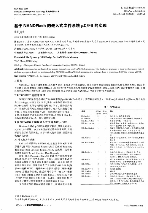
( 南 大学 集成 电路 学 院 。 苏 南 京 2 0 9 ) 东 江 10 6
摘要 : 绍 了基 于 NANDFah的 嵌入 式 文件 系统 的 实现 , 介 ls 其硬 件 平 台是 嵌 入 式 芯 片 S P 0 0与 NANDFah结 合 的 高性 能 嵌入 式 E 42 I s
3在 S P 0 0上实现嵌 入式 文件 系统  ̄ /S E 42 CF
M ci 公 司 的  ̄ /SJ 高度 可移 植 、 固化 的 嵌 入 i u rm CF L 2 是 可 式 F T文件 系统 。I /S的设 备驱 动 结 构非 常简 单 , 需 A  ̄ F C 只 要 读 写 扇 区的 底层 函数 。对 于 未 格 式化 的设 备 , 需 要 提术 原 理 C 8lF
T 5 5 2 东 芝公 司 出产 的 6 M 字 节(y ) A D Fah芯 片 。其 存 储 空 间分 为 4个  ̄(l e 4 9 块 (l k, C 8 1H ̄ I 是 4 BtN N l e s Pa ) 0 6个 Bo )每个 块 分 n共 c 为3 2页(ae, 页 为 5 8字 节 , 中 1 节 是 用来 形 成 Pg)每 2 其 6字 N N A D结 构 的 , 际存 储 数据 使 用 5 2 节 。擦 除 至 少是 实 1字 表 1 P B B结构 对 一 块操 作 , 写 可 以对 页 进行 操 作 。要 对 某 页 进 行 写操 读 作前 . 必须 先 进 行 擦 除 操 作 , 而一 次 除擦 的最 少 空 间是 一 个 块 , 果该 块 中其他 页 已经存 在 数 据 , 须 先备 份 起 来 , 如 必 然 后 在擦 完 该块 后 . 一 起 写 到指 定 区域 。 再
1引 言
嵌入式写flash的过程

嵌入式写flash的过程嵌入式系统是一种特殊的计算机系统,它通常用于控制、监测或执行特定任务。
在嵌入式系统中,Flash存储器被广泛应用于存储程序代码、数据和配置信息。
下面将介绍嵌入式系统中如何使用Flash 存储器的过程。
Flash存储器是一种非易失性存储器,它可以在断电后保持数据的完整性。
在嵌入式系统中,Flash存储器通常用于存储操作系统、应用程序和固件等软件。
下面是使用Flash存储器的一般过程:1. 首先,开发人员需要了解嵌入式系统的需求和功能。
根据系统的需求,确定所需的Flash存储器容量和接口类型。
接口类型包括SPI、NAND、NOR等不同的接口标准。
2. 接下来,开发人员需要选择合适的Flash存储器芯片。
根据系统需求和成本考虑,选择容量适当且性能稳定的Flash存储器芯片。
3. 在确定了Flash存储器芯片后,开发人员需要进行硬件设计。
这包括将Flash芯片与嵌入式系统的主控芯片相连接,并根据接口标准进行电气连接和信号交互。
4. 在硬件设计完成后,开发人员需要编写软件驱动程序。
这些驱动程序通常是嵌入式操作系统的一部分,用于控制Flash存储器的读写操作。
驱动程序需要根据Flash芯片的接口标准和通信协议进行开发。
5. 在软件驱动程序开发完成后,开发人员可以开始编写应用程序。
应用程序通常是嵌入式系统的核心功能模块,它将使用Flash存储器来存储和获取数据。
开发人员需要使用驱动程序提供的接口函数来读写Flash存储器中的数据。
6. 在应用程序开发完成后,开发人员需要进行测试和调试。
他们可以使用仿真器或调试器来验证Flash存储器的读写操作是否正常,并确保数据的正确性和完整性。
7. 最后,开发人员需要对系统进行整体验证和性能测试。
这包括测试系统的稳定性、响应时间和功耗等指标,以确保系统在各种工作条件下都能正常运行。
嵌入式系统中使用Flash存储器的过程涉及硬件设计、软件驱动程序开发、应用程序编写以及测试和验证等多个环节。
fatfs 详解
fatfs 详解【原创实用版】目录1.FATFS 简介2.FATFS 的特点3.FATFS 的应用领域4.FATFS 的优势与不足5.结论正文1.FATFS 简介FATFS(File Allocation Table File System)是一种适用于嵌入式系统的文件系统,由 Keil 公司开发。
FATFS 是一种可扩展的、可恢复的、易于使用的文件系统,适用于管理存储设备上的文件和数据。
它支持FAT12、FAT16 和 FAT32 三种文件分配表格式,因此可以适应不同存储容量的设备。
2.FATFS 的特点(1)可扩展性:FATFS 支持多种文件分配表格式,可以根据存储设备的容量进行选择,最大支持 2TB 的存储空间。
(2)可恢复性:FATFS 具有自动纠错功能,能够在读取数据时检测到错误并尝试修复。
同时,它还提供了一种称为“垃圾回收”的机制,用于回收已删除文件的存储空间。
(3)易于使用:FATFS 提供了丰富的应用程序编程接口(API),方便开发人员在嵌入式系统中进行文件操作。
3.FATFS 的应用领域FATFS 广泛应用于各种嵌入式系统,如智能家居、工业控制、消费电子等。
在这些领域,FATFS 可以提供可靠的文件存储和管理功能,满足设备对文件系统的需求。
4.FATFS 的优势与不足(1)优势:FATFS 具有较好的可扩展性和可恢复性,能够适应不同存储容量的设备。
同时,它提供了丰富的 API,便于开发人员进行文件操作。
(2)不足:尽管 FATFS 在嵌入式领域应用广泛,但它在某些方面存在局限性。
例如,与 extFS、yaffs 等其他文件系统相比,FATFS 在存储性能和空间利用率方面表现较差。
此外,FATFS 主要针对小容量存储设备,对于大容量存储设备而言,管理效率较低。
5.结论FATFS 是一种适用于嵌入式系统的文件系统,具有可扩展性、可恢复性和易于使用等特点。
在多种应用领域中,FATFS 都能提供可靠的文件存储和管理功能。
fatfs findfrist 介绍
fatfs findfrist 介绍fatfs是一种用于嵌入式系统的文件系统,它提供了对存储设备的访问和管理功能。
findfirst是fatfs中的一个函数,用于在指定目录下查找第一个文件或子目录。
在嵌入式系统中,存储设备通常是以闪存或SD卡的形式存在。
为了有效地管理存储设备上的文件和目录,需要使用文件系统来组织和存储数据。
fatfs是一种轻量级的文件系统,它具有良好的兼容性和高效的性能,被广泛应用于各种嵌入式设备中。
在使用fatfs时,我们经常需要遍历存储设备上的文件和目录。
findfirst函数就是用来实现这个功能的。
它的作用是在指定的目录下搜索第一个文件或子目录,并返回相应的信息。
通过不断调用findnext函数,可以依次获取该目录下的所有文件和子目录。
findfirst函数的调用方式如下:```FRESULT f_findfirst (DIR* dp, // 目录对象指针FILINFO* fno, // 文件信息结构体指针const TCHAR* path // 目录路径);```其中,dp是一个指向目录对象的指针,fno是一个指向文件信息结构体的指针,path是要搜索的目录路径。
在调用findfirst函数之前,需要先打开目录对象,并初始化文件信息结构体。
调用成功后,函数将返回FR_OK,表示查找成功。
此时,文件信息结构体中的各个字段将被填充上第一个文件或子目录的信息,包括文件名、文件大小、文件属性等。
下面是一个示例代码:```FILINFO fno;DIR dp;FRESULT res;res = f_opendir(&dp, "0:/"); // 打开根目录if (res == FR_OK) {res = f_findfirst(&dp, &fno, "0:/"); // 查找第一个文件或子目录if (res == FR_OK) {// 获取文件或子目录的信息printf("Name: %s\n", fno.fname);printf("Size: %lu bytes\n", fno.fsize);printf("Attribute: 0x%X\n", fno.fattrib);}f_closedir(&dp); // 关闭目录}```通过调用findfirst函数,我们可以方便地获取存储设备上的文件和目录信息。
嵌入式技术基础知识单选题100道及答案解析

嵌入式技术基础知识单选题100道及答案解析1. 嵌入式系统中,以下哪个不是常见的微处理器内核?()A. ARMB. MIPSC. x86D. PowerPC答案:C解析:x86 主要用于个人计算机等通用领域,在嵌入式系统中不常见。
2. 以下哪种存储介质在嵌入式系统中具有非易失性?()A. SRAMB. DRAMC. FlashD. SDRAM答案:C解析:Flash 存储器在掉电后数据不会丢失,具有非易失性。
3. 嵌入式系统中,实时操作系统的主要特点是()A. 高资源利用率B. 高可靠性C. 强实时性D. 友好的用户界面答案:C解析:实时操作系统最主要的特点是强实时性,能保证任务在规定的时间内完成。
4. 以下哪个不是嵌入式软件开发的常用工具?()A. KeilB. IARC. Visual StudioD. GCC答案:C解析:Visual Studio 主要用于Windows 平台的通用软件开发,不是嵌入式软件开发的常用工具。
5. 在嵌入式系统中,中断向量表通常存储在()A. 内部FlashB. 外部FlashC. 内部SRAMD. 内部ROM答案:D解析:中断向量表通常存储在内部ROM 中,以保证系统启动时能正确响应中断。
6. 以下哪种通信接口常用于嵌入式系统的短距离低速通信?()A. SPIB. USBC. EthernetD. CAN答案:A解析:SPI 接口常用于短距离低速的嵌入式通信。
7. 嵌入式系统中,看门狗定时器的主要作用是()A. 定时唤醒系统B. 防止系统死机C. 实现精确计时D. 产生时钟信号答案:B解析:看门狗定时器用于监测系统运行,防止系统死机。
8. 以下哪种编程语言在嵌入式系统中应用广泛?()A. JavaB. PythonC. CD. Ruby答案:C解析:C 语言在嵌入式系统开发中应用广泛。
9. 嵌入式系统的电源管理技术主要目的是()A. 提高电源效率B. 降低系统功耗C. 稳定电源输出D. 增加电源输出答案:B解析:电源管理技术主要是为了降低系统功耗,延长电池续航等。
fatfs结构体

fatfs结构体FatFS结构体是一个用于嵌入式系统中的文件系统结构体,它提供了一种轻量级的、高效的文件系统解决方案。
在嵌入式系统中,文件系统是非常重要的,它可以让我们方便地管理储存设备上的数据,提供了对文件的读写操作,以及对文件系统的管理功能。
在嵌入式系统中,通常会使用Flash、SD卡等存储设备来存储数据。
而文件系统就是用来管理这些存储设备上的数据的。
FatFS结构体是一个用于管理FAT文件系统的结构体,它提供了一组API函数,可以方便地对文件进行读写操作,以及对文件系统进行管理。
FatFS结构体通常包括以下一些成员变量:1. FATFS对象:表示一个FAT文件系统的对象,用于管理文件系统的状态和参数。
2. FIL对象:表示一个文件对象,用于管理文件的状态和参数。
3. DIR对象:表示一个目录对象,用于管理目录的状态和参数。
4. FATFS配置:用于配置FAT文件系统的参数,如簇大小、扇区大小等。
通过使用FatFS结构体提供的API函数,我们可以方便地对文件系统进行操作。
比如,我们可以通过f_mount函数来挂载一个FAT文件系统,通过f_open函数来打开一个文件,通过f_read和f_write 函数来读写文件,通过f_opendir和f_readdir函数来打开和读取目录等等。
除了提供对文件系统的基本操作外,FatFS结构体还提供了一些高级功能,比如对长文件名的支持、对文件属性的设置、对文件系统的格式化和检查等。
这些功能可以让我们更方便地管理文件系统,提高系统的可靠性和性能。
总的来说,FatFS结构体是一个功能强大、易于使用的文件系统解决方案,适用于各种嵌入式系统中。
通过使用FatFS结构体,我们可以方便地管理文件系统,实现文件的读写操作,提高系统的可靠性和性能。
希望本文对读者能够有所帮助,谢谢!。
无线传感器网络课件:Contiki操作系统

Contiki操作系统
2.3 安 装
Contiki操作系统
目前,Contiki操作系统开发小组将Contiki源码托管到github中。为了方便开发,我们需 要将Contiki操作系统的源码部署到本地。Cotniki源码默认环境为Linux操作系统,本节还将 介绍在Windows系统下的环境部署。
创建进程(还未投入运行)以及进程退出(此时进程还没从进程链表中删除)时,进程状态 都为PROCESS_STATE_NONE。
Contiki操作系统
1.进程初始化 系统启动后需要先将进程初始化,通常在主函数main()中调用函数process_init(),进程 初始化主要完成事件队列和进程链表初始化,将进程链表头指向NULL,当前进程也设为 NULL。 2.创建进程 创建进程实际上是定义一个进程控制块和进程执行体的函数,PROCESS宏实际上声明 了一个函数并定义了一个进程控制块,新创建的进程next指针指向NULL,进程名称为Hello world,进程执行体函数指针为process_thread_hello_world_process,保存行数的pt为0,状态 为0,优先级标记位needspoll也为0。PROCESS定义了结构体并声明了函数,还需要实现该 函数,通过宏 PROCESS_THREAD来实现。宏PROCESS_BEGIN包含switch(process_pt->lc) 语句,这样被中断的进程将再次获得执行并可通过 switch 语句跳转到相应的case,即被中断 的行。 3.启动进程 函数process_start()用于启动一个进程,首先判断该进程是否已经在进程链表中,然后将 进程加到链表,给该进程发一个初始化事件PROCESS_EVENT_INIT。
Contiki操作系统
littlefs 代码结构

littlefs 代码结构LittleFS是一种基于Flash存储器的嵌入式系统文件系统,它提供了一种简单易用的API来操作Flash存储器,支持多种微控制器和芯片。
下面是一个简单的LittleFS代码结构示例:```c#include "littlefs.h"#define BOARD_FLASH_SIZE (16 * 1024 * 1024) // 假设Flash芯片大小为16MB// 初始化LittleFSvoid init_littlefs() {littlefs_mount(& LITTLEFS, &flash_dev, LITTLEFS_MOUNT_AREA_DEFAULT);// 在此处添加文件系统操作代码}// 文件操作函数int file_open(const char* path, int oflag) {struct file* file = littlefs_open(path, oflag);if (file == NULL) {return -1; // 文件不存在或打开失败}return 0; // 文件打开成功}int file_read(struct file* file, void* buf, size_t size) { return littlefs_read(file, buf, size);}int file_write(struct file* file, const void* buf, size_t size) {return littlefs_write(file, buf, size);}int file_close(struct file* file) {return littlefs_close(file);}```上述代码中,`init_littlefs()`函数用于初始化LittleFS,它调用`littlefs_mount()`函数将文件系统挂载到指定的区域,并在该区域中添加文件系统操作函数。
NAND Flash存储管理的jkffs嵌入式文件系统说明书

International Conference on Communication and Electronic Information Engineering (CEIE 2016)To establish file system in industrial storage managementHui-Zhong LiuInstitute of Applied Mathematics Hebei Academy of sciences, Shijiazhuang, 050081,ChinaE-mail:****************Aiming at the Nand flash which is widely used in industrial storage management, theembedded file system named “jkffs”is established. In “jkffs”, a direct addressingalgorithm is described; tnode-tree, variable-tnodelength are used to address most kinds ofnand flash; the method of chunk group is mentioned also. The dynamic wear-levelingalgorithm and static wear-leveling algorithm according to the different erasing times ofblock are presented in “jkffs” to realize the garbage-collection and wear-leveling.Keywords: Jkffs; Ttnode-tree; Variable-tnodelength; Tthreshold.1. IntroductionNAND Flash memory is widely used in the industrial storage management in which embedded system is the core. The log-structured file system designed according to the physical structure characteristics of NAND Flash can solve the embedded system of mass storage management issues.NAND Flash array can be divided into a series of blocks. Each block contains a number of pages, and the block is the smallest erasable unit. Erasing a block means defining all the bits as "1" (defining all bytes as “FFh”). Writing operation, through the programming, turns erased bits from "1" to "0". The unit of reading and writing is the page, the page contains data area and leisure area (OOB, out-of-band), and OOB area is used for software designer. Writing Page and erasing block are the basic operations of NAND Flash. Programming all bytes of blocks for OXFF can release space [1].2. Establishment of The File System2.1. The basic ideas of the file systemThe file system we establish is named “jkffs”. Additional information is stored in OOB area, which is designed to realize the management of NAND FLASH.All the components in the file system, including file, directory, links, devices etc., are entirely regarded as a file .Each file has a special head page store file to preserve the head of mode, length, file name, father object labeling and other information. The basic unit for writing in NAND Flash is the Page (Page) called chunk in the file system, which has different meanings. Page refers to the actual data storage areas on the NAND Flash Memory, while the chunk is the logical data storage areas allocated by the file system. Their sizes can be different.With 2048+64byte as a page of NAND Flash chips, for example, the file system use 8 Byte on OOB district to store the relative file system information [2], and design a erasing-times mark (Erase_num, 8 bits), to recover block and realize the wear-leveling. The directory structure of the file system must be built in the memory during the process of loading the system. Reading OOB contents is only needed to scan each Chunk and from the system marks in the OOB, it can be determined whether the Chunk is head or data. Then according to the contents of the file head chunk and the information such as object ID, chunk ID of data chunk, establish a corresponding object in the memory for each file. After all the Block has been scanned, it would establish the relationships of all objects, and form a kind of architecture in RAM. Thus, the file system would be loaded successfully [3].2.2. Addressing of the file systemEfficient addressing can be realized by creating a node tree. Structure definition: union jkffs_Tnode_union {union jkffs_Tnode_union *internal[8];}This is a pointer array of length 8. The node tree at the bottom, created according to this structure, becomes the leaf nodes and the middle is internal node. They have the same structure. When the nodes is the internal nodes, each element of the array will point to the next layer of child node; When the node is the leaf node, the array will be splitted into 16 long integer with N bits (Tnodelength), which is the storage location of the file contents in the flash (that is, chunkid).The Tnodelength of leaf nodes determines the maximum addressed space for the file system. For example, Tnodelength = 16, means it can represent 216 =65536 chunk.. As for a NAND flash with 2K chunk , the largest flash address space c is 128 M.It is very convenient to find the files through the node tree. Each tnode used by the internal node has 8 pointers, so three binary codes are needed to index it,therefore when the tree grows a layer high, three codes would be added into the ChunkID. In turn, each three nonzero ChunkID represents a layer of the internal nodes. Meanwhile, each Tnode used by leaf nodes has 16 pointers, so four binary codes are needed to index it.When tnode structure just started to be built, only the lowest level tnode would be established. And when the number of the Chunk was more than 16, an internal tnode would be established in the tree, and NO. 0 pointer would point to the Lowest Level Tnode. While more and more Chunk is read, new tnode will be added and the node tree is also more and more higher.2.3. Variable-Tnodelength in the node treeTnodelength of bottom node in the node tree determines the maximum space which can be addressed by file system . If The size of the chunk is 512 byte, 32 MB NAND Flash need 65536 chunks, and it needs 16 bit to index chunk. Similarly, 64MB nand flash needs at least 17 bit to index all the chunk and 128 MB NAND Flash needs18 bit. In order to facilitate processing, the tnodeSize must be the multiple of 32bit, tnodeSize = (tnodelength * 16) / 8, the unit is Byte. Tnodelength represents the length, because the Tnode of level 0 is 16 physical chunk index. From the foregoing, tnodelength is the size of physical chunk index, and the unit is bit. In order to make tnodeSize the multiple of 4 Byte, 64 M flash’s chunk index bits has to be 18 bit at least. Thus tnodelength = 18 can directly addressed 128 MThe way by increasing tnode-length can realize the management of the most large capacity of NAND Flash on the market at present, say, tnodelength = 20, the file system has the maximum space: 220 * 2 K = 2G for addressing. But such established node tree occupy too much RAM space in embedded system, which affects system performance, and it is not quite flexible for the protean design of embedded system.In system initialization process the information of NAND Flash is first read, the total number of pages can be obtained by multiplying blocks of Flash ( nblocks) by pages of each block, which means that file system need to manage these pages, and then figure out tnodelength of bottom node .specific algorithm is as follows:1) C alculated the total number of pages x = nChunksPerBlock * nBlocks2) w hen X > 1, shift X 1 to right ,bits= bits+13) r epeat , until x <= 14) i f X is odd number,X=X+15) endFlow chart as shown in Fig. 1Bits is bit length, and assign to tnodelength. This way can solve the problem that fixed tnodelength occupies too much RAM in the system, and can manageFig. 1 Tnode-length algorithm flow chartIn the actual system design, if bits is too large, Chunk array can be considered. Make one Chunk to match more pages, through which can reduce the tnodelength.Thus,the goal of managing NAND Flash memory can also be achieved. That is, through synthesizing certain chunk into a group with a same Id, may also increase the addressing chunk scope. At this time, the Pages of chunk are different. Supposing that a Chunk corresponds two pages andtwo continuous pages can becalled d_Chunk, including 4096bytes data, here d_Chunk [0], d_Chunk [1] correspond relevant page separately, as shown in Fig. 2:Fig. 2 Chunk array and Page relationship schemes3. Garbage- Collection and Wear-LevelingThe life of the flash memory is limited, it is determined by the maximum erasing time of the block .Therefore, wear-leveling algorithm should be design to distribute the erasing and writing operation evenly on each block and its impact on performance should be as low as possible. The process of erasing blocks and reuse it is called “garbage-collection”. Considering the using frequency of data with garbage-collection and wear-leveling, we designed two algorithms: dynamic and static wear-leveling algorithm.3.1. Dynamic wear-leveling algorithmThe working range of Dynamic wear-leveling algorithm is the updated frequently data space and unused space, it will be realized in the writing of data.Fig. 3 Garbage-collection Flow chartThe algorithm supplies a good way to manage the dynamic data in flash memory. It can guarantee a fixed number of free blocks, as well as can solve data writing delay and accumulation. Two values were used in the blockrecovery algorithm above, they are Min and TH1. Min is the number of recovered dirty block each time when the idle block list is empty. Next, TH1will be explained.In this algorithm, garbage-collection will happen when free block list is empty, while the recovery of dirty block may need to copy the effective data of dirty block first, so the erasing should be done by descending order of useless data page when recovering block, here TH1 means the lower limit of dirty block though “Aggressive Mode”, the recovery can be operated from the beginning of the list of dirty block when the value is more than that.The Min must meet the conditions for Min ≥ TH1.If Min is too large, the number of free blocks will increase, accordingly, the available memory space will reduce; If Min is too small, it cannot solve the problem of data accumulation completely. In the file system, Min is 1/10 of the total block, namely Min = nBlocks / 10, TH1 = Min / 2.3.2. The realization of static wear-levelingIn the practical application of the embedded system data storage have such characteristics: most files are small files, but large files take up most of the storage space; the blocks of small files are updated much frequently. Thus the following situation will appear: the erasing blocks of small files have more erasing times than that of big files, which leads erasing times of small files’erasing blocks will reach the upper limit of erasing times faster and the life of the whole flash memory will be used up.In order to deal with this kind of static read-only data, we designed static wear-leveling algorithm. When the garbage-collection was triggered, read the EraseNum from OOB of the erase block in the clean blocks list, which marked the erasing times, then find out biggest and smallest erasing times. Then do subtraction between them, if the value is bigger than threshold, it can be concluded that erase with minimum number of erasing stored static data, and it needed to be moved. And because the static data are usually bigger and take up more erase blocks, the number of blocks with the minimum time of erasing is more than 1. Therefore, in order to better achieve erase equilibrium, it is necessary to scan the clean block list again after moving operation, and find out the block with maximum erasing times. Specific algorithm is divided into the following steps:1)S can clean block list, and find out the blocks with the biggest and smallest erasing times, then record the number EraseMax and EraseMin respectively, and name the blocks A and B respectively.2) I f “EraseMax - EraseMin≥TH2”, erase block B store the static data, it must be done with moving operation.3) s elect one block from the free block list, copy the data of A to it; Then erase A, and then copy the data of B to A; And then put B to the dirty block list for the storage of data updated frequently.4) R epeat above three steps, until “EraseMax - EraseMin≥TH2” is false, That is, all the static data have been moved.The value of TH2 is very important in the algorithm. If the threshold is too large, the number of static file storage blocks needed to be released will be greater than that of free blocks, and effective data cannot be all received. Conversely, if threshold is too small, blocks for static data file storage cannot be released promptly, and frequent data moving will affect the performance of the system. Usually it is better to set the value of TH2 between 200 to 500. In this file system TH2 = 250.4. ConclusionAt present the most reasonable management of NAND flash memory of the file system mostly uses the log-structured design ideas, such as JFFS, yaffs, etc. The file system “jkffs ” is developed and completed .Practice has proved that “jkffs ” could flexibly manage many NAND Flash with various size at present. References1. Samsung Corp. Flash Memory K9K4G08U0M DataSheet[S], Nov. 2015.2. SUN Feng and ZHANG Fu-xin, “Research an Improvement Of YAFFSFile System”, Computer Engineering, vol. 34, pp. 258-261 March 2014.(In Chinese).3. Wookey. YAFFS Direct User Guide. 2013-07-26. http :// /.。
基于spi-flash的fatfs配置
基于spi-flash的fatfs配置——王京石硬件平台:stm32f103VCT6、w25x16软件平台:fatfs R0.10由于产品需要存储大量数据,stm32单片机存储有限需要使用外部flash辅助存储。
考虑各方面原因最后选用了一款spi-flash型号为w25x16,spi总线操作,拥有2M的存储单元。
为了方便,我们想到了使用文件系统fatfs。
此文档记录了配置流程,为以后做参考。
一、底层移植Fatfs的diskio.c与diskio.h文件用于兼容底层接口,主要配置过程就是重写disk_initialize、disk_status、disk_read、disk_write、disk_ioctl、get_fattime六个函数以兼容不同的硬件设备。
1、设备初始化DSTATUS disk_initialize (BYTE pdrv)用于初始化硬件设备,在本次项目中主要就是初始化SPI总线接口,这个底层函数在执行应用层的open、write、read等函数是都会被执行。
本项目没有对flash进行分区操作,因此设备号应该为0。
DSTATUS disk_initialize (BYTE pdrv /* Physical drive nmuber (0..) */){if(pdrv == 0) //设备号为0则进行初始化操作{SPI_Flash_Init();return 0; //返回0表示成功}else{return STA_NODISK;}}2、读取设备状态DSTATUS disk_status (BYTE pdrv);用于读取设备状态,判断设备是否处于空闲状态,由于本项目使用的存储单元为spi-flash所以始终是可以操作的状态,因此始终返回OK就可以。
DSTATUS disk_status (BYTE pdrv /* Physical drive nmuber (0..) */){if(pdrv == 0) return 0;else return STA_NODISK;}3、读扇区操作DRESULT disk_read (BYTE pdrv, /* 物理设备号*/BYTE *buff, /* 读取数据缓冲*/DWORD sector, /* 扇区号*/UINT count /* 读取的扇区个数(1-128)*/)使用读操作在指定扇区里读取出数据。
嵌入式Flash文件系统的设计与实现
ef i t .t a l rvd unln fc nl Icna opo ie ora i i e y s j l g ̄a ms oeh net l blyo e ddss ms h s m n a c e i it f mbd e t oue t h r a i e e ye w
h i es se t efl y tm . Ke w o d :fa hm e o ; l yse ; e i n S y r s l s m  ̄ f es tm d sg ; TR71 F; F 08 C i 0 K9 28 UO
1 引言
随着嵌入 式计算机技术 的快速发展 ,各种应 用对 存储设备 的要求也越来越高。嵌入式计算机 系统 由于 受成本 、功耗、体积等 因素 的影响而普遍采用大容量
De ina dI p e e t t no b d e ls i y tm sg n m lm n a i f o Em e d d F a hF l S se e
CHEN — h n LIZhiGa g GuiS e g, - n
( e at n f o ue n i eig C insin s tt o e h oo y T iag2 5 1, hn ) D pr me t mp tr gn r , he - u gI tue f c n lg , a n 14 C ia oC E e n h ni T c 1
- 1、下载文档前请自行甄别文档内容的完整性,平台不提供额外的编辑、内容补充、找答案等附加服务。
- 2、"仅部分预览"的文档,不可在线预览部分如存在完整性等问题,可反馈申请退款(可完整预览的文档不适用该条件!)。
- 3、如文档侵犯您的权益,请联系客服反馈,我们会尽快为您处理(人工客服工作时间:9:00-18:30)。
一种微嵌入式Flash文件系统——μEFFS摘要:针对Flash存储器的特性提出一种分层文件系统架构,抽象出逻辑存储器作为中间层,屏蔽了底层物理器件操作上的不足。
本文件系统非常适合1GB以下容量的Flash存储器,具有可移植性高、访问效率高、寿命均衡等特性。
关键词: Flash存储器, Block, Page, 逻辑存储器, FAT随着嵌入式系统应用的迅速发展,嵌入式系统被广泛应用于各行各业,嵌入式系统的数据存储问题随之变成了一个最核心的关键问题。
由于Flash器件的迅速普及,使得Flash存储器的使用变得十分重要。
同时,Flash器件本身固有的擦写寿命、不可字节擦除等特点也使Flash器件存储管理变得非常复杂。
目前嵌入式系统领域已有了一些较为成熟的Flash文件系统,如:嵌入式Linux中普遍使用的JFFS2日志文件系统、YAFFS文件系统。
但是这些文件系统本身比较大,适合于大系统运行;并且经实践检验,这些文件系统对寿命的均衡处理并不像宣传的那样好,文件系统效率和可靠性也有待提高。
本文通过中间抽象逻辑存储器建立一种短小精炼、高性能、高可靠性、适合于嵌入式小型设备的嵌入式Flash文件系统——μEFFS。
实际上,通过更改底层物理存储器(软件),此文件系统也可以很方便地移植到其他器件上。
而且通用文件系统(如:FAT文件系统)很容易移植到本文提出的中间层逻辑存储器上,从而使得通用文件系统也获得了Flash文件系统的特性,如:寿命均衡。
1 Flash存储器特性(1)NAND Flash器件特点:高存储密度,采用页读写(读写速度快)、块擦除方式操作;容易发生位反转;存在坏块(存储不可靠性);容量一般较大(大于32MB);擦写寿命一般为100万次。
(2)NOR Flash器件特点:随机读写、块擦除;坏块少;器件本身存储可靠性高;擦写速度较慢;容量一般较小(小于16MB),擦写寿命一般为10万次。
(3)块(block):擦除的最小单元。
(4)页(page):即扇区,写的最小单元(NorFlash写的最小单元是字节,无页的概念)。
(5)擦除:存储单元的相应数据位由“0”变成“1”。
Flash器件和普通存储器件不一样,它只能采用块擦除和片擦除两种操作方式。
2 Flash器件存储管理由于Flash器件的读写特性,使Flash器件存储管理较为复杂,且容易出问题。
(1)寿命均衡问题:如果经常对同一单元进行擦写操作,这些单元将很快达到寿命极限,导致损坏。
(2)效率问题:如果每次改写1个字节的数据都采用擦写方式,将导致操作效率低下。
(3)NOR和NAND两种Flash区别明显。
嵌入式Flash文件系统需解决的核心问题都是围绕寿命均衡产生的,同时要兼顾性能和可靠性,最好能同时兼容两种Flash器件(NOR和NAND)。
3 μEFFS的核心原理建立一种完美的“逻辑存储器”,在此逻辑存储器上,可以完全像操作硬盘一样进行读、写操作。
系统层次结构如图1所示。
这样利用抽象中间层逻辑存储器完全屏蔽了底层物理存储器的具体实现,同时各层之间接口简单,简化了系统,提高了系统的可移植性。
中间层逻辑存储器将复杂的Flash操作简单化。
系统结构如图2所示。
中间层逻辑存储器是对物理器件的一种抽象,这样做的好处是上层文件系统无需考虑底层的具体实现,同时有利于移植到其他物理器件上。
为适应各种不同的器件需要,系统建立统一的逻辑扇区Logic Sector(LS)。
逻辑扇区大小和物理扇区相等,但是逻辑扇区的物理位置不固定,其实际地址通过BSAT来确定。
同时系统为每个逻辑扇区编号(LSN),这个就是逻辑扇区访问的惟一指示器。
对于每个物理块建立一个BSAT(块内扇区分配表,占用该块第一个扇区),用以描述这个块内所有扇区使用情况,分配表的每个单元最高2位表示扇区使用情况,剩下各位为逻辑扇区号。
例如BSAT表项采用16位(即BSAT16),BSAT表项结构如表1所示。
这样对整个存储系统的访问就完全变成对逻辑扇区的访问了。
系统本质是建立逻辑扇区到物理扇区的映射表,同时在操作过程中维护这个映射表。
4 底层物理存储器用于访问物理层硬件的主要函数有:(1)FlashEraseChip():芯片整片擦除。
(2)FlashEraseBlock(INT32U dwBlockNo):块擦除。
(3)FlashWrite(INT32U dwAddr,INT8U * pBuff,INT32U dwSzie):将缓冲区的数据写入目标地址处。
(4)FlashWrite1Sec(INT32U dwSecNo,INT8U * pBuff):向目标扇区写数据。
(5)FlashRead(INT8U * pBuff,INT32 dwAddr,INT32U dwSzie):从指定地址处读数据。
(6)FlashRead1Sec(INT8U * pBuff,INT32U dwSecNo):从指定扇区读数据。
5 中间层逻辑存储器5.1 系统初始化对Flash进行扫描,建立Flash空扇区表和物理扇区映射表。
(1)空扇区表:EmptySecTable[SecNum/8],表中每一位表示一个扇区,为1表示该扇区为空,否则该扇区非空。
(2)物理扇区映射表:PhySecTable[LogicSecNum],表中每个单元的值为物理扇区号。
5.2 读访问(1)根据PhySecTable[]找到逻辑扇区对应的物理扇区号。
(2)根据物理扇区号计算出物理地址。
(3)根据物理地址和扇区大小读取数据。
5.3 修改访问(1)先按读访问,读取扇区数据。
(2)在内存中修改数据。
(3)根据EmptySecTable[]选取一个空扇区,将修改后的数据写入新扇区。
(4)改写新扇区所在块的BSAT表,标记该扇区为有效状态,同时将逻辑扇区号写入BSAT。
(5)修改EmptySecTable[]表中该扇区为非空扇区。
(6)修改原扇区的BSAT项,标记为无效状态。
注:修改访问都选择一个新物理扇区(page),然后写入数据,再将原物理扇区标记为无效,从而达到寿命均衡访问。
5.4 缓冲块系统保留两个块用于碎片整理缓冲,缓冲块也称交换块,如果要实现更好的寿命均衡,也可以采用逻辑块的形式建立缓冲块。
5.5 Flash碎片整理Flash碎片整理分为手动整理和自动整理。
如果系统空扇区少于20%时,系统将自动进行碎片整理。
(1)系统复位初始化时,通过EmptySecTable[]判断是否需要整理;如果需要,则整理出一个块(block)。
(2)增加数据或修改数据时,如果发现空扇区少于10%,则整理出一个块,然后再进行操作。
(3)由于碎片整理比较耗时,所以每次只整理出一个块,目的是提高单次操作的性能。
(4)手动整理将对整个存储器进行整理,它可以在空扇区少于40%的情况下进行。
(5)整理过程:先擦除缓冲块(Buff block),然后将欲整理的块中有效扇区全部按顺序转移到缓冲块中,再擦除该块,最后将缓冲块中的数据原样复制到该块。
整理后需要更新空扇区表和块扇区分配表。
(6)整个系统只有碎片整理程序才会进行擦除操作,因此各块的寿命(次数)实际上就等于碎片整理的次数。
(7)碎片整理均衡策略:碎片整理每次只整理一个物理块,设立一个碎片整理块指针,用于指示下次需整理的块。
这样保证均衡整理各块,均衡了各块寿命。
5.6 中间层逻辑存储器主要函数(1)LogicMemFormat():擦除整片Flash,供上层调用。
(2)LogicMemInit():系统复位初始化调用,通过扫描Flash产生空扇区表和物理扇区映射表。
(3)ReadLogicSec(INT8U * buff,INT16U wLogicSecNo):根据逻辑扇区号读取扇区数据。
(4)WriteLogicSec(INT16U wLogicSecNo,INT8U * buff):将数据写入逻辑扇区,这个要考虑是追加还是修改。
(5)INT16U GetAFreeSec():获取一个空扇区号(未使用的物理扇区号)。
(6)FlashMemRep1Block():碎片整理1块。
(7)FlashMemRepAll():整片碎片整理。
6 上层文件系统在中间层逻辑存储器的基础上,可以建立各种类型的文件系统。
这样建立的文件系统已经具有良好的Flash文件系统特性。
本文件系统采用类似于FAT文件系统的处理方法。
(1)主引导记录MBR(保留区):包含启动代码和分区表,这个区主要借鉴了已有文件系统的设计思想(采用磁盘文件系统类似的方法处理),主引导记录占用逻辑扇区0。
实际上只要有BIOS的支持,本文件系统完全可以和已有的文件系统一样引导操作系统或者应用软件(只要搜索到逻辑算区0就找到了主引导记录);采用分区表的方法则有利于扩大整个文件系统管理空间的大小(如采用FAT16格式,4个分区表项分别指示4个不同的分区,相当于文件系统所能管理的空间扩大了4倍)。
主引导记录占用逻辑扇区0。
(2)系统引导记录DBR:用于指示文件分配表的位置、大小、个数和根目录区位置、大小、项数。
系统引导记录占用逻辑扇区1。
(3)文件分配表(FAT):用于指示文件的逻辑扇区号链,由于建立了物理扇区映射表,所以,可以高效地进行数据访问。
文件分配表本身占用逻辑扇区号,文件分配表的大小、个数,由系统引导记录指示。
(4)文件目录表(FDT):分为根目录和子目录。
子目录实际上也是文件(和普通文件完全一样),这里不详细讨论。
根目录表主要目的用于指示根目录中各文件(含子目录)在FAT中的第一个扇区号。
根目录的位置和大小在系统引导记录中指示。
7 系统整体运行机制(1)系统初始化:系统启动时进行初始化,构建中间层逻辑存储器。
此时建立空扇区表和逻辑扇区到物理扇区的映射表。
(2)文件读、写操作:根据主引导记录(逻辑扇区0)找到所在分区引导记录(系统引导记录);根据分区引导记录找到根目录区;根据根目录项,找到文件分配表(FAT)中相应的入口;根据FAT入口进行文件读、写操作。
上述所有操作都是根据逻辑扇区号进行访问的,实际访问通过查找物理扇区映射表进行。
本文通过中间层抽象逻辑存储器建立了一种Flash文件系统,并命名为μEFFS。
μEFFS特别适合于小型嵌入式系统(8位、16位、32位系统均可良好运行),具有寿命均衡、性能好、可靠性高的特点,经受了实践的考验。
通过对本系统的裁剪,很容易将其移植到单片机系统中,这样也给目前的低端8位单片机系统提供了一种数据存储解决方案。
