智能水泵控制器—A9(2013款)
水泵智能保护控制器

• 三、主要技术指标
• ·堵转动作时间: ≤1.5秒 ·空载保护动作时间: ≤20秒 ·本机功率损耗:静态功率:3.5W,动态功 率:4.5W ·过流动作时间: 1秒→1分钟(反时限特性: 电流越大时间越短) ·液位控制方式:脉冲电极探头检测,讯号 控制距离≤1000米 ·压力控制方式:电接点压力表、常开常闭 型压力开关、浮球液位开关 ·防护等级:IP22
• 四、安装与使用
• 1、将控制器固定在墙壁上,打开接线盒, 按标签提示接好电源、水泵以及探头线。 注意探头线不能短路,不能挨着水池壁。 如用空载保护,则不能接下水池讯号线。 2、开机:连接好所有的线后,闭合空气 开关,再把控制器面板上的开关,拨至 “ON”,水泵即可开机。用户可以用面板上 的“ON/OFF”开关来开启水泵或关闭运行 的水泵,但此时请注意,控制器内带电, 请注意安全!
• ·工作电压:AC380V/50Hz ·匹配电机功率:0.37-15KW ·采用数码芯片控制,集上、下液位和压力控制于一体 ·具有自动、手动两种工作模式可供选择 ·具有缺相、过载、空载、超低压等保护功能 ·空载重启时间1~60分钟可调 ·具有故障记忆功能,5次故障原因可轻易查阅 ·具有交流数码信号检测功能,探头更耐用、抗干扰更强 ·人性化设计,安装便捷、操作简单、维修方便 ·国内首创防锈保护功能,能有效防止电机锈死
• 9、过/欠压保护:开机后,只要将讯号线端子台上方过/ 欠压保护开关拨到ON状态,开关下方有指示灯亮,即开 启了过欠压保护功能,电压保护范围为:380V±15%, 电网电压超过此范围即开始保护。5分钟后自动恢复。如 电压达不到要求,则继续保护。
10、防锈运行:防锈运行是指电机在一个周期内(每隔48 小时为一个周期)没有运行过的电机会瞬间运行转动1次(转 动时间约3~5秒)。设置:将控制器内的防锈运行开关拨 至ON,下方指示灯亮,表示已经开启防锈功能。 11、复位:水泵出现过载或缺相故障(过/欠压、空载保 护不属故障)时,必须先排除故障,再按复位键,水泵才 能恢复工作。
欣灵牌水泵智能控制器XLQ-SK10 18A010E4说明书
地址:浙江乐清经济开发区纬十九路号 Http://www.-.c328Iin nC技术咨询:-- 出版日期:20年月40082367752001XLQ-SK1018A010E4系列水泵智能控制器非常感谢您使用欣灵牌水泵智能控制器,使用前请阅读使用手册!序言序 言XL Q-SK10系列水泵智能控制器外观精美、操作简便,指示内容简单明了,操作更加人性化无需任何参数设置,另外控制器还具有多种实用性功能:手/自动切换模式,能够灵活的应用与各种环境;可支持水位浮球触点信号、电接点压力表信号;高、中、底水位探头信号;在自动运行状态具有两用、一用一备、故障时自动换泵功能;可以适用各种“供水”“排水”深井泵、排污泵、管道泵、增压泵、多级泵等。
目 录水泵智能控制器目录一、系统概述 (1)二、型号说明 (1)三、技术参数 (1)四、使用环境 (1)五、产品外形尺寸、安装尺寸 (2)六、接线端子说明 (2)七、操作面板说明 (4)八、拨码开关KB1用途说明 (4)九、实用案例 (6)系列水泵智能控制器是本公司新型研发的“智能控制器”,本XLQ-SK10产品采用高新科技电子集成化设计,具有操作简单,指示直观、外形精美等优点。
使用本产品即可节省线材及外围元器件,安装简单快捷节省装配时间提高效率。
主要适用于消防控制设备、排污设备、喷淋控制设备水塔供水等多种恒压自动/手动供水控制箱配套使用。
一、系统概述二、型号说明XLQ SK10 2设计序号水泵智能控制器欣灵电气12表示:一控一;表示:一控二三、技术参数1AC220V.额定工作电压:2.3A/AC220V内部继电器输出负载电流:3.AC220V适配交流接触线圈电压:4.DC12V电接点压力表及液位探头控制电压类别:5.5W控制器额定功耗:<6.外部传感器信号:电接点压力传感器、浮球传感器、四、使用环境110℃40℃.工作环境温度:-~2.工作环境为:无水滴、蒸汽、腐蚀、易燃、灰尘及金属微粒的场所.相对湿度<%395-1-A无表示:标准型;表示:基础型,A水位控制排水型水泵智能控制器水泵智能控制器七、操作面板使用说明XLQ-SK102XLQ-SK1011、指示灯状态说明:1)、运行灯:绿色常亮表示水泵正在运行。
智能温控操作说明
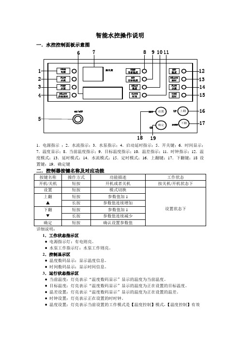
智能水控操作说明一.水控控制面板示意图1.电源指示;2.水流指示;3.水泵指示;4.启动延时指示;5.开关键;6.时间显示;7.温度显示;8.当前温度指示;9.目标温度指示;10.温差指示;11.时钟指示;12.温度模式;13.延时模式;14.水流模式;15.定时模式;16.上翻键;17.下翻键;18设置键;19.确定键详细说明:1.工作状态指示区●电源指示灯:有电则亮。
●水泵工作指示灯:水泵工作则亮。
2.控制显示区●温度数码显示:显示温度信息。
●时间数码显示:显示时间信息。
3.运行状态指示区●当前温度:灯亮表示“温度数码显示”显示的温度为当前温度。
●目标温度:灯亮表示“温度数码显示”显示的温度为正在设置的目标温度。
●温差设置:灯亮表示“温度数码显示”显示的温度为正在设置的温差。
●时钟设置:灯亮表示正在设置的时时钟。
●温度设置:灯亮表示当前设置的工作模式是【温度控制】模式,【温度控制】有效●延时控制:灯亮表示当前设置的工作模式是【延时控制】模式,【温度控制】和【延时控制】均有效。
●时间控制:灯亮表示当前设置的工作模式是【时间控制】模式,【温度控制】和【时间控制】均有效。
4.按键区●开关:单击切换控制器的开关状态。
●设置:进入设置模式,每按一次,设置参数切换一次。
●确定:对设置的参数进行确认,或者设置同一工作模式下的下一个参数。
●▲:对正在闪动的参数上调。
●▼:对正在闪动的参数下调。
三.工作设置说明1.设置【水流控制】工作模式调试:按【开关键】十秒,时钟那里出现08:00的时候,机器会自动恢复为水流+温度+延时模式,注:设置状态下,用户5s内无操作,控制器存储当前设置并自动返回运行状态,下同。
2.设置【延时控制】工作模式:设置方式:按【设置】,使【延时控制】灯亮,此时,“时间数码显示”闪动,用户按【▲】或【▼】调节延时时间分钟部分。
设置完分钟后,按【确定】跳到延时时间参数中的秒部分设置。
再次按【确定】,返回到运行模式。
智能水泵控制器GYXF330-2LP-B产品手册
GYXF330-2LP-B 智能水泵控制器产品说明手册版本:V1.8警告!本装置只能由电气专业人士才允许安装,所有的电气安装和维修工作都必须由专业的工程师进行。
对于因不遵守本手册的说明所引起的故障,厂家将不承担相关责任。
警告!微电脑智能水泵控制器是不可以在现场进行维修的机器。
不要试图修理损坏的单元,请与供应商或当地授权的维修站联系。
警告!不要试图进行本手册中没有涉及的任何测量,器件的更换或其他维修工作,否则将可能导致保修失效,危及正常运行,延长设备停机时间和增加费用等后果。
感谢您选用本产品,本设备属精密电子仪器,为确保您的人身、设备以及财产的安全,在使用本设备前,请您务必阅读本手册,并在以后的搬运、安装、运行、调试与检修过程中遵照执行。
注意!欲获取详细的技术信息,请与当地供应商或当地微电脑智能水泵控制器代理处联系。
目录一、系统简介----------------------------------------------------------------------------------31、概述-----------------------------------------------------------------------------------------32、产品特点-----------------------------------------------------------------------------------33、面板操作-----------------------------------------------------------------------------------34、外形尺寸-----------------------------------------------------------------------------------3二、接线端子说明---------------------------------------------------------------------------4三、系统参数描述---------------------------------------------------------------------------51、参数默认值对照表------------------------------------------------------------------------52、管理权限密码设置------------------------------------------------------------------------53、参数进入方法-----------------------------------------------------------------------------64、参数设置方法-----------------------------------------------------------------------------65、完整参数描述-----------------------------------------------------------------------------6四、有限责任--------------------------------------------------------------------------------- 9五、一次线路应用例------------------------------------------------------------------------10一、系统简介1、概述GYXF330-2LP-B型智能水泵控制器,是应市场需求推出的一款高性能设计的一款产品,主要用于排污泵、稳压泵、给水泵等控制。
低压水泵面板控制器说明书
SECTION 16486PUMP PANEL CONTROLLERS – LOW VOLTAGEPART 1 GENERAL1.01 SCOPEA. The Contractor shall furnish and install the low voltage pump panel controllers as specifiedherein and as shown on the contract drawings.1.02 RELATED SECTIONSA. Section 16475 – Circuit Breakers and Fusible Switches – Low VoltageB. Section 16481 – Motor Starters – Low VoltageC. Section 16902 – Electrical Control Devices1.03 REFERENCESA. The pump panel controllers shall be designed, manufactured and tested in accordancewith the latest applicable standards of NEMA, ANSI and UL.1.04 SUBMITTALS – FOR REVIEW/APPROVALA. The following information shall be submitted to the Engineer:1. Master drawing index2. Dimensioned outline drawings3. Conduit entry/exit locations4. Cable terminal sizes5. Wiring diagrams6. Nameplate schedule7. Ratings including:a. Voltageb. Horsepower and/or continuous current8. Product data sheetsB. Where applicable, the following additional information shall be submitted to the Engineer:1. Key interlock scheme drawing and sequence of operations2. Mimic bus1.05 SUBMITTALS – FOR CONSTRUCTIONA. The following information shall be submitted for record purposes:1. Final as-built drawings and information for items listed in Paragraph 1.04, and shallincorporate all changes made during the manufacturing process2. Wiring diagrams3. Seismic certification as specified1.06 QUALIFICATIONSA. The manufacturer of the assembly shall be the manufacturer of the major componentswithin the assembly.B. For the equipment specified herein, the manufacturer shall be ISO 9001 or 9002 certified.C. The manufacturer of this equipment shall have produced similar electrical equipment for aminimum period of five (5) years. When requested by the Engineer, an acceptable list ofinstallations with similar equipment shall be provided demonstrating compliance with thisrequirement.D. £Provide Seismic tested equipment as follows:1. The equipment and major components shall be suitable for and certified to meet allapplicable seismic requirements of the International Building Code (IBC) for zone 4application. Guidelines for the installation consistent with these requirements shall beprovided by the switchgear manufacturer and be based upon testing of representativeequipment. The test response spectrum shall be based upon a 5% minimum dampingfactor, IBC: a peak of 2.45g’s (3.2-11 Hz), and a ZPA of 0.98g’s applied at the base ofthe equipment. The tests shall fully envelop this response spectrum for all equipmentnatural frequencies up to at least 35 Hz.-- OR –1. The equipment and major components shall be suitable for and certified to meet allapplicable seismic requirements of the California Building Code (CBC) through zone 4application. Guidelines for the installation consistent with these requirements shall beprovided by the switchgear manufacturer and be based upon testing of representativeequipment. The test response spectrum shall be based upon a 5% minimum dampingfactor, CBC: a peak of 2.15g’s, and a ZPA of 0.86g’s applied at the base of theequipment. The tests shall fully envelop this response spectrum for all equipmentnatural frequencies up to at least 35 Hz.-- OR --1. The manufacturer may certify the equipment based on a detailed computer analysis ofthe entire assembly structure and its components. Guidelines for the installationconsistent with these requirements shall be provided by the switchgear manufacturerand be based upon testing of representative equipment. The equipment manufacturershall document the requirements necessary for proper seismic mounting of theequipment2. The following minimum mounting and installation guidelines shall be met, unlessspecifically modified by the above referenced standards.a. The Contractor shall provide equipment anchorage details, coordinated with theequipment mounting provision, prepared and stamped by a licensed civil engineerin the state. Mounting recommendations shall be provided by the manufacturerbased upon approved shake table tests used to verify the seismic design of theequipment.b. The equipment manufacturer shall certify that the equipment can withstand, that is,function following the seismic event, including both vertical and lateral requiredresponse spectra as specified in above codes.£ Note to Spec. Writer - OptionalNote to Spec. Writer – Select onec. The equipment manufacturer shall document the requirements necessary for properseismic mounting of the equipment. Seismic qualification shall be consideredachieved when the capability of the equipment, meets or exceeds the specifiedresponse spectra.1.07 REGULATORY REQUIREMENTS1.08 DELIVERY, STORAGE AND HANDLINGA. Equipment shall be handled and stored in accordance with manufacturer’s instructions.One (1) copy of these instructions shall be included with the equipment at time ofshipment.PART 2 PRODUCTS2.01 MANUFACTURERSA. Eaton / Cutler-Hammer productsB. __________C. __________The listing of specific manufacturers above does not imply acceptance of their products that do not meet the specified ratings, features and functions. Manufacturers listed above are notrelieved from meeting these specifications in their entirety. Products in compliance with thespecification and manufactured by others not named will be considered only if pre-approved by the Engineer ten (10) days prior to bid date.2.02 PUMP PANEL CONTROLLERSA. Electromechanical Controller1. Magnetic starters through NEMA Size 7 shall be equipped with double-break silver alloycontacts. The starter must have straight-through wiring. Each starter shall have one (1)normally open auxiliary contact2. Coils shall be of molded construction through NEMA Size 7. All coils to be color-codedthrough Size 5 and permanently marked with voltage, frequency and part number3. Overload relays shall be an ambient compensated bimetallic-type with interchangeableheaters, calibrated for 1.0 and 1.15 service factor motors. Electrically isolated normallyopen/normally closed contacts shall be provided on the relay. Visual trip indication shallbe standard. A test trip feature shall be provided for ease of troubleshooting and shallbe conveniently operable without removing components or the motor starter. Overloadto have (+/-) 24% adjustability, single-phase sensitivity, and isolated alarm contact, andmanual or automatic reset-- OR --3. Solid-State Overload RelayNote to Spec. Writer – Insert data in blanksNote to Spec. Writer – Select onea. Provide a solid-state overload relay for protection of the motors. The relay shall beCutler-Hammer type CEP7 or approved equal.b. The overload relay shall provide high accuracy through the use of state-of-the-artmicroelectronic packaging technology. The relay shall be suitable for applicationwith NEMA Size 1 through Size 7 motor starters.c. The overload relay shall be modular in design, be an integral part of a family ofrelays to provide a choice of levels of protection, replace existing electromechanicaloverload relays, and be listed under UL Standard 508.d. The overload relay shall have the following features:1. Be self-powered2. Class 10 or 20 fixed tripping characteristics3. Manual or automatic reset4. Phase loss protection. The relay shall trip in 2 seconds or less underphase loss condition when applied to a fully loaded motor5. Visible trip indication6. One normally open and one normally closed isolated auxiliary contact7. Test button that operates the normally closed contact8. Test trip function that trips both the normally open and one normally closedcontacts9. A current adjustment range of 3.2:1 or greater10. Ambient temperature compensated4. NEMA Size 00 through 2 starters shall be suitable for the addition of at least six (6)external auxiliary contacts of any arrangement normally open or normally closed . Size3 through 7 starters shall be suitable for the addition of up to six (6) external auxiliarycontacts of any arrangement normally open or normally closed5. Across-the-line magnetic starters for motors up to 600 hp, 600 volts shall be Cutler-Hammer Freedom Series type “ECN” enclosed-- OR --A. Vacuum Starters1. Vacuum starters shall incorporate “low-chop” interrupters and limit chop currents to lessthan 0.5 amperes. Contact material to be silver tungsten carbide2. Interrupters shall have contact wear detection indicators3. Vacuum starters shall have front removable coil and auxiliaries4. The contactor coil shall utilize rectified AC current5. Provide a “push-to-test” button for Sizes 5 and 66. Vacuum contactors shall be Cutler-Hammer Class V200 for non-reversing andClass V210 for reversing7. Overload relays shall be an ambient compensated bimetallic-type with interchangeableheaters, calibrated for 1.0 and 1.15 service factor motors. Electrically isolated normallyopen/normally closed contacts shall be provided on the relay. Visual trip indication shallbe standard. A test trip feature shall be provided for ease of troubleshooting and shallbe conveniently operable without removing components or the motor starter. Overload Note to Spec. Writer – Select oneto have (+/-) 24% adjustability, single-phase sensitivity, and isolated alarm contact andmanual or automatic reset-- OR --7. Solid-State Overload Relaya. Provide a solid-state overload relay for protection of the motors. The relay shall beCutler-Hammer type CEP7 or approved equal.b. The overload relay shall provide high accuracy through the use of state-of-the-artmicroelectronic packaging technology. The relay shall be suitable for applicationwith NEMA Size 1 through Size 7 motor starters.c. The overload relay shall be modular in design, be an integral part of a family ofrelays to provide a choice of levels of protection, be designed to directly replaceexisting electromechanical overload relays, and be listed under UL Standard 508.d. The overload relay shall have the following features:1. Be self-powered2. Class 10 or 20 fixed tripping characteristics3. Manual or automatic reset4. Phase loss protection. The relay shall trip in 2 seconds or less under phase losscondition when applied to a fully loaded motor5. Visible trip indication6. One normally open and one normally closed isolated auxiliary contact7. Test button that operates the normally closed contact8. Test trip function that trips both the normally open/normally closed contacts9. A current adjustment range of 3.2:1 or greater10. Ambient temperature compensated-- OR --A. Motor Starters – IT Design1. Provide electromechanical type motor starters with coil control and overload integratedinto a single or dual microcontroller2. The motor starter shall operate over a temperature range of -40 to 149 degrees F (-40to 65 degrees C) and shall meet or exceed the following Standards and Certifications:UL, CSA, NEMA ICS1, ICS2, ICS5, IEC 60947-4-1, CE and KEMA where applicable.Devices shall meet Electromagnetic Compatibility (EMC) Requirements per EMC IEC61000-43. Provide one toroidal current sensor per phase accurate to 2% providing input to analogcircuitry and software, which yields a time-current curve paralleling actual motorheating. Motor FLA shall be set via a potentiometer for 1.0 or greater Service Factorsettings4. Provide user selectable overload Trip Class of 5, 10, 20 and 30 on each OverloadRelay. To adjust factory defaults, trip class shall be manually changed using the testbutton and FLA dial5. Provide phase loss and phase current unbalance protection. If the phase unbalance ofany phase is greater than, or less than, approximately 50% of the average, the device Note to Spec. Writer – Select onetrips. This feature is user enabled/disabled and manually changed using the Testbutton and FLA dial6. Provide each motor starter with a lockable cover that prevents unwanted tampering ofFLA dial settings once installed7. Provide a microcontroller with the following features:a. Monitor the nominal 24 Vdc and adjust the Pulse Width Modulation (PWM)accordingly to minimize utilized power and maximize contact sealed force.b. Energizes coil at full voltage and then applies Pulse Width Modulation.c. Monitors user control inputs (i.e., permissive {stop}, forward, reverse, local reset,remote reset, test/test to trip. Control inputs shall be rated are 24 Vdc (3–5 mA) witha plug and unplug lockable control connector.d. Operates an LED indicator which displays a flash sequence for thermal capacitiesover 70%, test button depression, trip indication, class setting, phaseenablement/disablement, and microcontroller reset condition.e. Monitors 3-Phase current into a common node.f. Sweeps the current waveform to avoid synchronizing with the current waveform.g. Provides Thermal Memory (in addition, Thermal Pile, Thermal Capacity) which shallbe saved to non-volatile memory for safety purposes in the event of a power loss orremoval and restore event.h. Controls an alarm output, which is a solid-state open collector or emitter type outputat 24 Vdc 250 mA.i. Shall solve a first order differential equation for an actual motor heating model tocalculate trip points.j. Provides an “alarm only” or “alarm without trip” mode for critical must-runapplications.k. Provides built-in logic to provide either 2- or 3-wire control, eliminating the need to provide and wire auxiliary contacts to seal-in and interlock the contactor coil.l. £Starter can be easily networked with the appropriate Starter Network Adapter device communicating to a factory bus.8. Control Voltages:a. The starter voltage shall be nominal 24 Vdc from 20 to 28 Vdc.9. Motor starters shall have replaceable fixed and movable contacts, Size 1 through 510. Motor starters shall have no laminations, shading coils, or magnet noise11. Accessoriesa. Motor starters shall accommodate auxiliary contacts per various maximumcombinations of single and dual auxiliaries. Maximum number of circuits shall be six(6) for Size 1 through 4 and twelve (12) for Size 5 starters. Contacts shall be ratedten (10) amperes continuous, 7200 VA make, 720 VA break for 120 Vac, 3600 VAmake, 360 VA break for 240 Vac, 1800 VA make, 180 VA break for 480 Vac 1440VA make, 144 VA break for 600 Vac, and 137.5 VA make and break for 125through 250 Vdc. No seal-in auxiliary contacts are required.b. Provide mechanical interlock on reversing contactors of a pivot-type mechanism toprevent closing of one contactor when the other is closed. Coil Controller energizesboth forward and reverse contactors providing one control point for wiring.£ Note to Spec. Writer – Optionalc. Provide control modules to perform the indicated input/output control functionsshown on the drawings. Module shall incorporate faceplates having membrane typepushbuttons and LED’s. All pushbutton and LED functions shall be provided withclearly written identification. Modules shall be provided with the ability to replaceconventional start, stop, hand, auto control functions, and overload reset function.Modules shall be provided with the ability to replace conventional indicating lightstatus of run, off, selector switch pushbutton position, and overload trip and circuitbreaker trip.12. Microprocessor-based motor starters shall be Cutler-Hammer IT series orapproved equal13. All printed wiring boards shall be conformal coated to provide environmental robustness14. £Motor starters shall provide Manual, Remote Reset, or Auto Reset capability2.03 ENCLOSURESA. The enclosure shall be NEMA 3R. £Provide [narrow], [standard], or [oversized] enclosure.2.04 ACCESSORIESA. Each starter shall be equipped with [HOA selector switch] [start pushbutton]. Unlessotherwise specified, the secondary shall be 120 Vac.B. Pilot devices, where specified, shall be oil-tight and mounted in the flange. Pilot lights shallbe transformer-type for extended lamp life. Pilot device nameplates shall be engravedphenolic or aluminum.C. Starters shall have [an adjustable instantaneous motor circuit protector (HMCP) type] [athermal-magnetic circuit breaker type] [a fusible type] [a non-fused type] disconnect device.D. £Where indicated on the drawings, pump panel controllers shall be suitable for ServiceEntrance use.2.05 £ALTERNATORA. An alternator shall be provided for duplexing and alternation of two pumps.PART 3 EXECUTION3.01 FACTORY TESTINGA. Standard factory tests shall be performed on the equipment provided under this section. Alltests shall be in accordance with the latest version of UL and NEMA standards.B. The manufacturer shall provide three (3) certified copies of factory test reports.£ Note to Spec. Writer – OptionalNote to Spec. Writer – Select one3.02 FIELD QUALITY CONTROLA. Provide the services of a qualified factory-trained manufacturer’s representative to assistthe Contractor in installation and startup of the equipment specified under this section. Themanufacturer’s representative shall provide technical direction and assistance to theContractor in general assembly of the equipment, connections and adjustments, andtesting of the assembly and components contained herein.B. The Contractor under the technical direction of the manufacturer’s service representativeshall perform the following minimum work.1. Inspection and final adjustments2. Operational and functional checks of controllers/starters and spare partsC. The Contractor shall provide three (3) copies of the manufacturer’s field startup report3.03 MANUFACTURER’S CERTIFICATIONA. A qualified factory-trained manufacturer’s representative shall certify in writing that theequipment has been installed, adjusted and tested in accordance with the manufacturer’srecommendations.B. The Contractor shall provide three (3) copies of the manufacturer’s representative’scertification.3.04 TRAININGA. The Contractor shall provide a training session for up to five (5) owner’s representatives for____ normal workdays at a job site location determined by the owner.B. The training shall be conducted by a manufacturer’s qualified representative.C. The training program shall consist of the following:1. Instructions on the proper maintenance and operation of the equipment.Note to Spec. Writer – Insert data in blanks。
泵军师.水泵控制器 安装说明书(三相一控一)
三. 基本功能1. 显示基本 1. 电流显示屏: 显示水泵实测工作电流,没有电流则显示 “0.0”。
2. V /Y (电压、压力)显示屏: 供水排水控制时显示电源实际工作电压。
压力控制时则显示管道压力的大小,没有接压力传感器时显示"- - -"; 3. 自动模式:“自动”指示灯常亮。
表示机子所有功能处于全自动运行状态。
手动模式:“手动”指示灯亮,表示不能自动;(只能按 键来控制) 4.水位指示灯:显示水池的实际水位及水量或电接点压力表的指针接触状态。
5.电接点压力表指示灯:压力控制时在水池指示灯位置显示实际压力状态,下 限时"低位”亮、中压时“中位”亮、上限时“高位”亮。
电压/压力数显屏管道缺水 指示灯传感器型号 指示灯上下限压力 指示灯过载/空载 指示灯高中低水位 指示灯缺相/过欠压 指示灯电流数显屏数显压力/型号上限下限设置定时启/停功能设置自动/手动 压力型号键键切换自动/手动指示灯过载/空载保护电流参数设置启动/停止控制按钮注:远传压力表引线接法由于不同厂家的压力表指针引线的标记和次序不同;所以安装的时候一定要看一下该厂的压力表说明书上的指针线路位置说明动指针接信号端口,剩下的线接正极。
图6:6.压力变送器的接法注:压力变送器引线接法本控制电路是电压型压力变送器,为不能接错;使用不同的压力变送器型号时,将面板里的型号设置成相配套的型号即可;注意:任意两个信号线不要短接和碰到;信号线不要跟电源线和水泵线缠绕在一起,要避开干扰强地方及电器(比如变压器或信号塔)远距离传输 更稳定 更方便接受压力变量按比例转换为标准输出信号。
将测压元件传感器受到的气体、液体等物理压力参数转变成 标准的电信号,以供给指示报警仪、记录仪、调节器等二次仪表进行测量、指示和过程调节。
主要功能电压/压力/水位显示定时功能 过压保护 欠压保护故障原因显示 故障报警 管道缺水 动/手动启动/停过载 空载 短路 缺相故障及排除方法。
智能水泵控制器说明书

智能水泵控制器 使用说明书● 安装使用产品前,请阅读使用说明书并妥善保管;● 控制器必须由熟悉低压电器技术的专业人员进行安装;● 进行安装、接线、拆卸、维护时必须断开电源;● 严禁通电状态下直接用手触摸带电元器件;● 控制器通电前必须进行可靠接地。
● 若使用发电机作控制器电源时,待发电机电源稳定后,才可给控制器通电!<一控二>智能控制器说明书水泵一 产品简介应用范围:适用于两台水泵(一控二)直接启动型的不锈钢/铸铁深井潜水泵、离心泵、管道泵等的自动控制及保护,尤其独特设计的无需安装下水池(水井)探头即可实现灵敏可靠的水泵干转停机保护功能,更方便深井潜水泵、管道泵的施工安装及节省费用。
特别设计的双泵自动轮换功能可最大限度降低水泵锈蚀现象,泵故障自动切换功能更使供水系统的可靠性得到保障。
本机型通过连接与其配套的远程同步显示控制器,可实现远程监控,远程同步显示控制器可实时显示电压、电流等工况,并实现所有控制功能。
主要特征:手动、自动工作时具有缺相、错相、超温、堵转、三相不平衡、过流、干转、过压、欠压的保护;可以实现液位、压力、浮球的自动控制,通过连接与其配套的远程同步显示控制器,可实现远程监控(RS485),远程同步显示控制器上可实时显示电压、电流等工况,并实现所有控制功能<选配功能>。
技术参数:额定输出功率: 参见机器功率铭牌额定工作电压:参见机器功率铭牌过流动作时间: 5秒-5分钟(反时限特性—电流越大时间越短)干转故障恢复时间: 30分钟(手动),自动状态下1秒后切换至另一台泵过流故障恢复时间: 5分钟(手动),自动状态下1秒后切换至另一台泵欠压/过压/三相不平衡恢复时间:2分钟(手动),自动状态下1秒后切换至另一台泵欠压动作电压: 标称电压80% 过压/欠压动作时间: < 5 秒过压动作电压: 标称电压115% 堵转动作时间: < 0.1秒缺相动作时间: <2秒 短路动作时间: < 0.1秒干转保护动作时间: 6秒 双泵自动轮换: 1:1轮换次数液位传输距离: ≤1000米 防护等级:IP54网络传输距离:1200米(采用双绞屏蔽型电缆 STP-120Ω(for RS485 & CAN one pair 20 AWG)液晶屏显示图注意:若遇雷雨天气,请务必关闭控制器输入电源注:高配机型具备:错相/三相不平衡/超温功能及故障干接点输出端口注:单相机型:无错相/缺相/三相不平衡功能强腐蚀性气体或液体机械冲击淋雨极端的冷和热。
泵宝中文说明书
水泵控制器非常感谢您选用水泵智能控制器,为了您正确使用本控制器,请在使用前仔细阅读本说明书,并妥善保存以供今后参考。
快速安装指南接线按控制器接线示意图,接好电源线和探头线。
过载设定将控制器内面板上的三档开关拨至“过载设置”,再左右调节控制器内面板上的电位器旋钮,调至您需设定的数值,空载设置指示灯会闪3下熄灯既表示设定ok。
试运行安装及设定完成后,按启动键试运行,试运行如还遇到其它困难,请详细阅读本说明书或与我司经销商联系!具体详细使用规则,以此说明书为准!注意事项注意事项1、安装本控制器时,一定要严格遵守国家电工操作规程,请勿带电作业,请专业电工安装,否则有可能出现触电事故!2、本控制器未装漏电保护开关,漏电无保护,可能引起严重的安全事故,请用户自行加装漏电保护装置。
3、如果本控制器未带空气开关,使用时必须增加空气开关,否则不能起到有效过载保护。
4、设定过载电流必须与电机正常工作电流相符,否则不能起到有效过载保护。
5、电机过载等故障后,务必先排除故障,再按启动键则重新启动。
如不排除故障,让电机启动,控制器和电机都很容易烧坏。
6、如电机频繁启动或超负荷工作,必须选用比电机功率大一个型号的水泵智能控制器,否则有可能烧坏电机或造成事故!7、本产品在一般情况下能起到保护作用(如过载等),能在部份情况下有效地保护电机,降低电机返修率,但不是所有情况下都能保护电机不被烧毁,例如:电机本身的质量问题或雷击等。
8、本公司只对本产品进行保修或维修,如用户使用本产品后,电机还出现故障或烧机,本公司不负责维修或赔偿!另外由于机器故障对用户造成的影响,本公司也不承担责任,例如:排污时由于机器故障造成地下室被淹等。
9、控制器安装环境要求:请安装在室内,避免太阳直接暴晒,或者淋雨。
使用温度:-10℃至40℃湿度:相对湿度不大于90%海拔高度:不超过2000m探头线耐温:105℃01 使用安装说明书一、产品包装水泵智能控制器说明书探头安装螺丝及胶塞1台1本1套各3个二、产品特点♦采用数码芯片控制,集上、下液位和压力自动控制于一体♦具有自动、手动两种工作模式可供选择♦具有过载、空载、超低压等保护功能♦具有空载重启时间1~240分钟可调♦具有故障记忆功能,5次故障原因可能轻易查阅♦专利交流数码讯号检测功能,探头更耐用♦安装方面,调试简单三、主要技术参数1、静态功率小于3.5W,动态功率小于4.5W;2、出厂默认值:A.过载设定默认值为:1.5KW为8A,2..2KW为11A;B.空载设定值为00.0A,空载保护后自动恢复时间为30分钟;3、最大控制距离:500米;4、过载保护反延时特性,时间误差为±15%:过载倍数 1.2倍 1.5倍2倍3倍5倍保护时间 50秒30秒15秒6秒1秒四、安装接线指南1、将控制器固定在墙壁上,打开接线盒,按标签提示接好电源、水泵。
KT系列智能换热机组控制器使用手册说明书

KT系列智能换热机组控制器(适用于KT356A型号)使用手册 卓越产品·及时服务KECHENG(上海恪成)是行业领先的供水控制器提供商。
致力于通过供水控制系统的优化使您的供水设备更稳定,同时成本更低。
企业发展历程:2008年起开始致力于触摸屏水泵控制器研发及代工OEM生产;2011年投资500万注册公司并建立专业的研发团队及生产流水线;2014年企业通过ISO9001:2008国际质量体系认证;2014年注册“KECHENG”商标;2015年新版本控制器通过欧盟CE认证并远销欧盟国家。
“卓越产品·及时服务”是我们永远追求的目标。
上海浦东嘉里城复旦附中青浦校区ISO9001认证CE认证专利证书智能水泵控制器产品主要由4大系列组成:1、KP 系列变频恒压供水控制器主要用于水泵恒压供水设备或无负压供水设备。
适用范围:居民生活用水、公共场所用水、商用大厦、灌溉、工厂等供水系统;锅炉、中央空调补水等。
2、KX 系列水泵巡检控制器主要用于水泵或消防巡检控制系统。
适用范围:水泵巡检系统、消防泵巡检系统等。
3、KL系列给排水控制器主要用于根据水箱或水池液位进行补水或排水。
适用范围:水箱补水、潜水排污、深井给水、污水提升装置等4、KT 系列换热温度控制器主要用于换热机组控制和变频温度循环控制。
适用范围:换热机组控制系统、中央空调循环水温差控制、地暖温度控制、太阳能循环水温度控制等。
目录一、公司介绍 (2)二、产品系列简介 (3)三、系统概述 (6)四、系统工作原理 (7)五、供水参数基本设定 (8)六、控制器的外形与安装 (9)七、控制器技术参数 (10)八、主界面与操作说明 (12)九、参数设置界面与操作说明 (16)十、系统设置界面与操作说明 (27)十一、应用案例 (29)十二、常见故障处理 (29)十三、注意事项 (30)十四、品质保证 (31)感谢选用恪成牌KT系列智能换热机组控制器。
三相水泵智能保护水位无线自动控制启 停电控柜说明书

三相水泵智能保护水位无线自动控制启停电控柜使用说明书型号SC33产品概述SC33型三相水泵无线水位自动控制启停智能保护电控柜,适合深井泵,潜水泵、离心泵、管道泵,液位/压力控制,又名智能水泵控制器,水泵智能控制器,智能水泵控制箱,水泵智能控制箱,泵控之宝。
额定工作电压AC380V/50HZ,匹配电机功率0.37-15KW,过流,缺相,短路,欠压,过压,干转保护。
三相水泵无线水位自动控制启停智能保护电控柜适用于0.37-15KW三相380V不锈钢/铸铁深井潜水泵、管道泵等的自动液位或自动压力控制及保护,尤其独特设计的无需安装下水池(水井)探头即可实现灵敏可靠的水泵干转停机保护功能。
产品广泛应用于深井泵、潜水泵、排污泵、管道泵、增压泵、多级泵、离心泵等;应用于生活供水、地下排污、高楼供水等。
优化功能:★增加手动、自动功能★手动状态下带过载、缺相保护★最优化的按键:设置简单,操作简单★探头免维护:一般情况下1-2年不用维护★电路集成度更高,产品故障率更低SC系列远程无线液位控制器,系我公司推出且拥有自主知识产权的智能化新产品,该控制器能解决水塔水池根据水位高低自动启停水泵的要求,可广泛应用在:水文、自来水、冶金、矿山、化工等行业。
可用来测量江、河、湖、海的深度和储水池、储水容器内的水位。
例如高山水库之间水位控制,高速公路消防水池水位控制,别墅的排水泵站群自动控制,小区泵房的自动控制,工厂水位水塔的自动控制,不用架设LAN线,不用中继站,不用开挖施工,用极小的投资,就能实现数台设备的远距离双向检测和控制,不但省去了弱电施工成本,后期也基本没有维护费用,避免盗割电缆造成的巨额损失,本控制器可以一对一无线通讯,也可以1对多,无线控制距离根据用户实际控制距离环境量身定制,免费无线电台控制距离0.1-几百公里,基于移动网传输的收费网络电台控制距离无限制,可全球遥控遥测。
该控制器不同于其它厂供应的调幅民用不可靠无线液位控制器,该控制器采用调频工业级耐高低温、抗电机干扰高的电路制造,该控无线制器溶入十几年无线工程经验,具有很高的稳定可靠完美性,具备多项先进而实用的技术功能,精湛的技术,优良的制造封装工艺,确保了本产品的高效、稳定、持久和免维护运行,高强的品质、坚固的结构、稳定的性能,胜任于野外恶劣的环境,是现代工业传统水位(液位)控制方式理想的无线液位控制更新换代产品。
智能型水泵控制器-泵管家
控制方动控制方式 双液位控制 / 压力表自动控制
液位控制 脉冲电极探头 或浮球开关检测
压力控制 电接点压力表
额定工作电压 AC220V/50Hz
额定输出功率 0.37KW-2.2KW
可用区域 室内
主要功能 控制功能 控制水泵数量 1台
手动启动 √
自动启动 √
保护定值一键式设定 √
保护定值面板设定 √
空气开关 ×
起动方式 直接起动
主轴防锈功能 √
液位\压力跳线转换 √
智能型水泵控制器-泵管家-恒压供水系统生产厂
产品型号: A2-i100-104 产品名称: 智能型水泵控制器 工作电压: AC220V/50Hz 适用功率: 0.37KW-2.2KW
规格参数 安装说明 售后服务
型号 A2-i100-104
适用范围 应用水泵 铸铁深进潜水泵、离心泵、管道泵等水泵
保护功能 缺相保护 √
短路保护 √
空转保护 √
欠电压保护 √
过电压保护 √
堵转保护 √
三相电流不平衡保护 √
防雷击保护 √
电机外壳温度保护 √
显示功能 查询功能* 故障查询、运行时间查询、水位显示(选配功能)
数值显示表 电压表、电流表
运行模式指示灯 √
Insentek智能灌溉方案
一、Inentek智能灌溉系统简介1.1 智能灌溉系统新定义目前农业灌溉系统存在的诸多问题,最关键的是灌溉策略没有依据,几乎全部都在凭经验灌溉,诸如灌溉定额、灌溉周期、一次灌水延续时间等,且全生育期都在用同样的灌溉制度;其次是没有反馈和优化,每次灌溉之后,并不确定有效灌溉量是多少,以及是不是符合作物需求。
即使目前高端的中控灌溉系统,依然以人工输入程序控制阀门启闭为主,存在灌溉制度不合理、控制系统管理难度大的诸多问题,同时水肥大量浪费,造成土壤板结和地下水污染。
生态农业已逐步成为未来农业的主流方向,减少化肥、农药用量近年也被大力提倡和推广,而实现精准水肥一体化灌溉,将水肥有效输送至作物根毛区,实现节约水肥、增产高效,避免浪费污染,则是切实的向生态农业发展的重要步骤,也是智能灌溉系统推行的意义所在。
真正的智能灌溉系统,是指能够根据目标作物、目标土壤、目标地点气象等情况,配合生态大数据系统,对目标区域进行基于人工智能的灌溉、施肥参数设定,并且控制一系列机电设备实施上述灌溉、施肥,以及根据传感器反馈评估灌溉、施肥效果自动改进人工智能决策,从而改变目前农业灌溉、施肥单纯依靠人力经验的现状,达到按照作物需求灌溉、施肥的精准水肥一体化灌溉方式。
1.2 智能灌溉系统特点(1)灌溉有依据:基于田间的基于作物根系的水分监测,执行灌溉决策,且灌后有反馈;(2)可靠性高:长期工作稳定可靠,免人工维护,且核心设备防水级别为IP65和IP68;(3)操作简便:提供多种操作模式,智能模式下一键启动。
(4)安全性高:超出系统流量、压力安全限值,系统启动报警并按照预设进行停灌处理,另外所有核心设备均带GPS定位,可实时查看位置及历史运行轨迹。
(5)集成度高:核心设备及平台都具有极高的集成度,不单独收通讯费等附加费用,且平台免费提供给用户,不按照模块逐项收费。
(6)扩展性强:拥有足够强大的硬件和软件功能,具备极强的扩展性,可为用户持续添加一般化的应用程序,且系统相对开放,允许用户自行开发特殊的应用程序模块。
水泵控制柜的组成
水泵控制柜的组成
水泵控制柜是一种用于控制和保护水泵的设备,其主要组成部件如下:
1. 电源部分:包括主电源开关、电源指示灯等,用于为控制柜提供电源。
2. 自动控制部分:包括液位控制器、压力控制器、温度控制器等,根据实际需求,对水泵的启动、停止进行自动控制。
3. 保护装置:包括过载保护、短路保护、缺相保护、泵体漏水保护、电机超温保护等,用于确保水泵在异常情况下能及时停止运行,防止设备损坏。
4. 操作面板:包括按钮、显示屏等,用于手动控制水泵的启停,以及显示水泵的工作状态。
5. 执行器:如接触器、继电器等,用于接收控制信号,实现对水泵的控制。
6. 通信接口:如RS485、以太网等,用于与其他设备(如上位机、PLC等)进行数据
交换和远程控制。
7. 辅助部件:如风机、加热器等,用于保证控制柜内部元件的正常工作。
8. 外接传感器:如液位传感器、压力传感器、温度传感器等,用于采集现场数据,提供给自动控制部分进行处理。
综上所述,水泵控制柜由多个部分组成,共同实现对水泵的自动控制和保护功能。
在实际应用中,不同场合和需求可能会有不同的控制方式和组成部件,以满足特定的使用要求。
智能水泵控制器-A2

输出端
外置
电源输入端
电容
一键整定
N L PE N1 L1 C
① ②③④ ⑤⑥
压力 液位 设置开关
上止点 下止点 公共线
安全地
2 2 0 V电 源
M ~
电机
注 意 大多数潜水泵、离心泵、 管道泵均已外置电容。
电源
第二步:外置电容的安装
M
电机
上止点 下止点 公共线
下水池
上水箱
第三步:一键电流整定
一键整定按钮 选择手 动模式
按下 运行键
等待正 常出水
按下 整定键
倒记时 2 0秒- 00秒
提 示:必 须在手 动状态进行整定
● 未 整 定前,液 晶 屏幕上 显 示 “未整 定 ” 字样 ● 整 定 完毕后, “ 未整定 ” 字 样将不 再 显 示 ● 机 器 整定后, 才 能对水 泵 进 行有效 保 护
常见典型控制应用接线图示水井抽水至上水箱探头控制免井下探头接法上水箱水塔水井抽水至上水箱探头控制下水池水井上水箱水塔水井抽水至上水箱控制水井抽水至上水箱控制免井下探头接法上水箱水塔下水池水井带溢出报警排水探头控制下水池水井带溢出报警排水浮球控制下水池水井l1n1电源外置电容电机l1n1电源外置电容电机l1n1电源外置电容电机l1n1电源外置电容电机l1n1电源外置电容电机l1n1电源外置电容溢出点下水池水井公共点中性大多数压力表上已注明接线编号通常的对应关系为压力表内的对应控制器的l1n1电源外置电容下水池水井公共点中性大多数压力表上已注明接线编号通常的对应关系为压力表内的对应控制器的调节弹簧压力开关电机l1n1电源外置电容电机l1n1电源外置电容下水池水井压力开关电机l1n1电源外置电容下水池水井
丹伏伺智能水泵说明书

丹伏伺智能水泵说明书产品尺寸:305mm乘125mm乘210mm产品包装:三层瓦楞纸箱,防变型,五层减震泡沫垫,防摔防震产品简述:过欠压保护六大保护功能:缺相保护,管道缺水保护,过载保护,空载保护,短路保护多重控制方式:浮球控制,探头控制,压力表控制,温度控制,上下水池双控。
产品详述:采用电脑芯片控制,集上、下液位和压力自动控制于一体;手动/自动切换方便,一键整定设置简单;三相电流同步显示,具有三相不平衡保护,具有过载、空载(干转)、缺相、短路、过\欠压迟延启动等保护功能,井下无水自停,有水自动起动,10次故障记忆功能,故障原因可轻松查阅,维修方便,具有防锈功能,能有效防止电机锈死。
(长时间不用泥沙塞死)集成电路控制省略了过去控制器的分离元件,增加了控制器的稳定性,节省安装时间,减少维修,多重工艺检验,长时间故障模拟充分老化可接浮球、压力开关、水位探头,报警器等外部控制装置。
产品型号适用功率SB-SH-3000D0.75-3KWSB-SH-4000D0.75-4KWSB-SH-7500D1-7.5KWSB-SH-11000D2.2-11KWSB-SH-15000D2.2-15KWSB-SH-18000D4-18KWSB-SH-22000D15-22KWSB-SH-25000D15-25KW应用:可广泛运用于高层建筑供水,车库,地下室排水,农田灌溉,工地临时用水,工程降水,家庭供水等。
售后服务:一年质保,终生维护产品广泛应用于深井泵、潜水泵、排污泵、管道泵、增压泵、多级泵、离心泵等;应用于生活供水、地下排污、高楼供水等。
1、按手动键启动水泵,水泵运行,任意键可停止水泵运行。
2、同时按下设置+手动键,听到蜂鸣器响声,然后按遥控器任意键,听到蜂鸣器响声,配对成功。
3、遥控器操作,遥控器侧面电源键打到ON位置,然后拉出天线,按遥控器开键启动水泵,按关键关闭水泵。
遥控器不使用时请将侧面电源开关拨到OFF位置,节省电池电源。
水泵控制器说明书
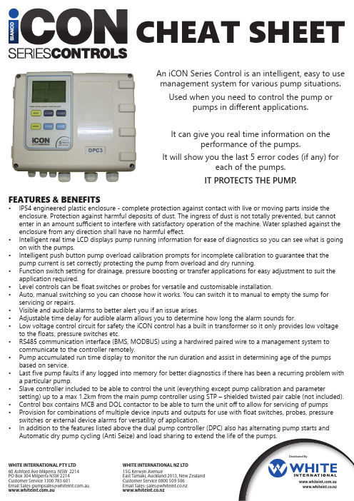
CHEAT SHEETFEATURES & BENEFITS • IP54 engineered plastic enclosure - complete protection against contact with live or moving parts inside the enclosure. Protection against harmful deposits of dust. The ingress of dust is not totally prevented, but cannot enter in an amount sufficient to interfere with satisfactory operation of the machine. Water splashed against the enclosure from any direction shall have no harmful effect.• Intelligent real time LCD displays pump running information for ease of diagnostics so you can see what is going on with the pumps.• Intelligent push button pump overload calibration prompts for incomplete calibration to guarantee that the pump current is set correctly protecting the pump from overload and dry running.• Function switch setting for drainage, pressure boosting or transfer applications for easy adjustment to suit the application required.• Level controls can be float switches or probes for versatile and customisable installation.• Auto, manual switching so you can choose how it works. You can switch it to manual to empty the sump for servicing or repairs.• Visible and audible alarms to better alert you if an issue arises.• Adjustable time delay for audible alarm allows you to determine how long the alarm sounds for.• Low voltage control circuit for safety the iCON control has a built in transformer so it only provides low voltage to the floats, pressure switches etc.• RS485 communication interface (BMS, MODBUS) using a hardwired paired wire to a management system to communicate to the controller remotely.• Pump accumulated run time display to monitor the run duration and assist in determining age of the pumps based on service.• Last five pump faults if any logged into memory for better diagnostics if there has been a recurring problem with a particular pump.• Slave controller included to be able to control the unit (everything except pump calibration and parameter setting) up to a max 1.2km from the main pump controller using STP – shielded twisted pair cable (not included).• Control box contains MCB and DOL contactor to be able to turn the unit off to allow for servicing of pumps • Provision for combinations of multiple device inputs and outputs for use with float switches, probes, pressure switches or external device alarms for versatility of application.• In addition to the features listed above the dual pump controller (DPC) also has alternating pump starts andAutomatic dry pump cycling (Anti Seize) and load sharing to extend the life of the pumps.An iCON Series Control is an intelligent, easy to use management system for various pump situations.Used when you need to control the pump or pumps in different applications.It can give you real time information on the performance of the pumps.It will show you the last 5 error codes (if any) for each of the pumps.IT PROTECTS THE PUMP .Distributed By:.au WHITE INTERNATIONAL PTY LTD60 Ashford Ave Milperra NSW 2214 PO Box 304 Milperra NSW 2214Customer Service 1300 783 601EmailSales:**********************.au .au WHITE INTERNATIONAL NZ LTD 15G Kerwyn Avenue East Tamaki, Auckland 2013, New Zealand Customer Service 0800 509 506EmailSales:*****************.nz APPLICATIONSDRAINAGE WITH AUTOMATIC PUMPS •Applied for drainage (where pumps have their own float switches)•Mainly used in instances where float cables can’t be run through the conduit from the sump to the control panel. •Generally because the builder has not laid a conduit large enough to fit: 2 x pump power leads and 3 x float cables.• All that is required are the pump power leads and one floatcable (overflow)BOOSTING • Applied for water supply by pressure control through pressure switch and pressure tank • High Rise Buildings • Hotels • Hospitals • Shopping Centres • Used in conjunction with a vertical multistage booster pump. The impellers boost the pressure of the water as it passes through to have enough pressure to service either a greater demand for water or a greater height than would otherwise be possible.•Instead of floats, pressure switches are connected to thecontrol panel to manage the pumps.TRANSFER •Applied for water supply or drainage by liquid level control through float switch or liquid sensor • Dam to Water Tower • Tank to Tank •Generally used when you need to move water from one location to another.•The float switches are installed in both the source and destination of the water storages. • iCON controller will only allow water to go to the destination ifit is needed and the source has water to accommodate.HOT WATER CIRCULATION • Applied for water supply by the thermal switch • High Rise Buildings • Hotels • Hospitals • Shopping Centres • Under Floor Heating • The hot water line must have a return line installed for a circulator pump to work.• If a thermostat is used you can set the temperature to kick in the circulator pumps to bring the cold water back to the boiler so that it is replaced by hot water.• Used in situations where it is inconvenient or impractical towait for hot water to come through the pipes.DRAINAGE • Applied for drainage by liquid level control through float switch or liquid probe • Flooding • Stormwater • Moves excess water from a primary location elsewhere.• In conjunction with the float switches or probes the iCON controller switches the pumps on and off as required to emptythe sump.PROGRAMME iCON CONTROLLER • Check that the pumps have been installed correctly as per the instruction manual for the desired application.• Check that the control panel is disconnected from the power supply and wait 2 minutes before opening the control panel.connect the power supply.• Calibrate the controller to the pumps.• Fill the sump with enough water to be able to start the pumps.• Press MODE and STORE keys together to unlock the controller and switch it to manual mode.•Press A START key to run pump A and confirm that the pump and all pipe network is in a normal working state.•Press the STORE button. The control panel will make a beep sound and a countdown starts from 5 to 0 with the LCD displaying:•Press B START key to run pump B and confirm that the pump and all pipe network is in a normal working state.•Press the STORE button. The control panel will make a beep sound and a countdown from 5 to 0 starts again.• Press MODE to return to automaticHOW DOES IT PROTECT PUMPS?•The controller itself will determine based on the pump calibration if anything is going on that requires attention.•There will be an audible and visible alarm to alert you of a problem.• Press A STOP to turn off the alarm for 5 minutes.• Read what is on the display.PROGRAMMINGCHANGING PARAMETER SETTINGS • Ensure panel is in manual and pumps are not running.• Press MODE for 5 seconds until the controller beeps and the first parameter will be displayed.• Press MODE to select to select the parameter code required.• Press A START to increase the value and A STOP to decrease the value.• Press MODE to select to select the next parameter code if required.• When completed press MODE for 5 seconds until the controller beeps.TROUBLESHOOTING PUMP NO CALIBRATION• Pump no calibration is flashing• Fill the sump with enough water to be able to start the pumps.• Press MODE and STORE keys together to unlock the controller and switch it to manual mode.• Press A START key to run pump A and confirm that the pump and all pipe network is in a normal working state.• Press the STORE button. The control panel will make a beep sound and a countdown starts from 5 to 0.• Press B START key to run pump B and confirm that the pump and all pipe network is in a normal working state.• Press the STORE button. The control panel will make a beep sound and a countdown from 5 to 0 starts again.• Press MODE to return to automaticOVERLOAD OR PUMP STALLED• Overload or pump stalled is flashing.• Pumps may not have been calibrated properly• Remove previous calibration by:• Switching it to manual mode (MODE & STORE)• Press A STOP for 30 seconds until the panel beeps. Pump A no calibration should be displayed.• Press B STOP for 30 seconds until the panel beeps. Pump B no calibration should be displayed.• Calibrate the pumps one at a time by pressing START let the pump run and then STORE.• Return to automatic by pressing MODE.OVERTEMP• Overtemp is flashing.• The red jumper leads between terminals 10 and 12, (and 9 and 11 for dualpumps) has been removed.• Replace the leads – unless there is a set of pump microtherm wires to connect.DRY RUN• Check that the float switches are not set too low, or if they are caught up inside the tank allowing air into the pumps.• For surface mounted pumps, ensure that the pumps are primed and that any valving is open to allow flow into the pumps.REPEATED START• This will flash if there are more than 5 starts per minute.• Usually occurs on pressure systems. Check the tank pre-charge and bladder, pressure switch settings or defects.• Pumps may be oversized or have flat performance curves.UNDER V or OVER V• Voltage is out of range.• The pump will attempt to restart every 5 minutes until voltage is restored to normal.• If it is unresolved, please discuss with the product managerPHASE REVERSAL• 3 Phase only• Incoming phase rotation has changed from when control panel was originally connected.• When connecting pump rotation during commissioning, the pump connections must be changed, NOT the incoming power connection.• If this has occurred, change the incoming connections and the pump connections together. NETWORK CONNECTION ERROR• This is normal if the slave controller is not installed.• If the slave controller has been installed and the error message appears, it means that there is no network connection or a connection error between the pump control box and the slave controller(or computer).。
泵宝水泵智能控制器SM5B1使用说明书
泵宝水泵智能控制器SM5B1使用说明书
水泵智能控制器操作说明:
1、按手动键启动水泵,水泵运行,任意键可停止水泵运行。
2、同时按下设置+手动键,听到蜂鸣器响声,然后按遥控器任意键,听到蜂鸣器响声,配对成功。
3、遥控器操作,遥控器侧面电源键打到ON位置,然后拉出天线,按遥控器开键启动水泵,按关键关闭水泵。
遥控器不使用时请将侧面电源开关拨到OFF位置,节省电池电源。
故障说明:
1、远距离遥控水泵不起作用,更换9V叠层电池。
2、380水泵控制器手动指示灯闪烁时,说明缺相,请检查电线是否接好。
注意事项:
1、设定过栈电流必须与电机正常工作电流相符,否则不能起到有效过拔保护。
2.如果木机未带空气开关,使用时必须增J川空气开关和漏电开关,否则短路及漏电无保护,可能引起严匝的安全事故。
如电机频繁启动或超负荷l作,必须选用比电机功率大一个型号的水
泵智能控制器,否则有可能烧坏电机或造成事战!
仫安装本控制器时,一定要严格遵导国家电工操作规程,请勿带电作业,请专业电工安装,否则右可能出现触电事故!
5、木产品对电机在一般情况下能起到保护作川(如过载、缺相等),能直部份情况下有效地保护电机,降低电机返修率,但不是所有情况下都能保护电机不皱烧毁,例如∶电机本身的质量问题或雷击等。
6、本公司只对本产品进行保修或维修,如用户使用本产品后,电机还出现故障或烧机,木公司不负责维修或赔偿!
7、控制器安装环境要求∶请安装在室内,遥免点阳点接爆晒.或者淋雨。
使用温度:-109至40°C
湿度:相对湿度不大于90%海拔尚度:不超过2000m。
基于国产MCU电子水泵控制器的设计

算得出。
2021 年第 44 卷
图 4 电流采样电路
1.4 LIN 通信电路 LIN 是一种低成本的串行通信网络,用于实现汽车
中的分布式电子系统控制。LIN 的目标是为现有汽车 网络(CAN 总线)提供辅助功能。通过 TJA1027 将协议 控制器生成的发送数据流转换成优化的总线信号,以使 电 磁 辐 射(EME)最 小 化 。 LIN 总 线 输 出 引 脚 通 过 内 部 终 端 电 阻 拉 高 。 对 于 主 应 用 ,应 在 引 脚 VBAT 和 引 脚 LIN 之间连接一个与二极管串联的外部电阻。接收器 会检测 LIN 总线输入引脚上的接收数据流并通过引脚 RXD 将其传送至微控制器。LIN 通信电路如图 5 所示。
图 1 系统设计框图
1.1 电源转换电路
电源转换电路的设计主要是为了各模块电压的不
同需求而提供分层电压。整个系统采用外置直流电压
12 V 输入,没有内置电池,所以外部电源急需要给电机
供 电 ,同 时 也 需 要 给 整 个 系 统 供 电 ,经 电 源 模 块 调 节 后
输出 5 V 电压给 MCU 供电。因此根据 IC 需要,设计了
图 2 电源转换电路
1.2 电机驱动电路 电机驱动电路是电子水泵控制器硬件电路设计中
最重要的电路之一,其设计好坏直接决定电机的驱动效 率高低。在本控制器中,主控芯片输出引脚产生的控制 信 号 无 法 直 接 驱 动 MOS 管 ,为 了 增 大 驱 动 能 力 ,选 择 IR2101S 芯片为功率驱动器,该芯片的主要作用是结合 外 部 电 容 ,使 电 压 泵 升 ,达 到 驱 动 MOS 管 的 电 压 值 。 IR2101S 的 HIN 和 LIN 引脚接收来自单片机的一对互补 PWM 控制信号,这一对 PWM 信号分别控制连接在 HO 和 LO 引脚的 Q1MOSFET 和 Q2MOSFET,其打开或关闭的 反应时间只有约 150 ns,打开和关闭时间分别为 100 ns 和 50 ns;自举电容 C1 选择 1 μF/100 V;每个控制芯片能控 制 2 个 MOS 管 ,因 此 总 共 需 要 6 个 MOS 管 ,3 个 控 制 芯 片。如图 3 所示为本控制器的功率驱动电路原理图。
