郝思曼HC4900力矩限制器用户手册
转矩测试仪操作规程(3篇)
第1篇一、概述转矩测试仪是一种用于测量旋转扭矩的仪器,广泛应用于工业生产、科研试验等领域。
为了确保转矩测试仪的正确使用和测量结果的准确性,特制定本操作规程。
二、适用范围本规程适用于所有型号的转矩测试仪,包括但不限于静态扭矩测试仪、动态扭矩测试仪等。
三、操作前的准备工作1. 确认仪器是否处于正常工作状态,包括电源、显示屏、传感器等。
2. 检查测试仪与被测对象之间的连接是否牢固,确保连接线无破损、接触良好。
3. 熟悉被测对象的工作原理和性能,了解测试目的和要求。
4. 准备好测试所需的工具和辅助设备,如扳手、量具、记录本等。
5. 确认测试环境符合要求,包括温度、湿度、照明等。
四、操作步骤1. 连接被测对象(1)将测试仪的传感器连接到被测对象的旋转轴上,确保连接牢固。
(2)将测试仪的电源线连接到被测对象的电源接口,确保电源线无破损、接触良好。
2. 参数设置(1)根据被测对象的特性,在测试仪上设置合适的测试参数,如测试模式、测试速度、测试次数等。
(2)根据需要,设置传感器参数,如量程、分辨率等。
3. 测试(1)启动测试仪,开始进行扭矩测试。
(2)观察测试仪显示屏上的扭矩值,确保数据稳定。
(3)根据测试要求,调整测试速度和测试次数。
4. 数据记录(1)在测试过程中,记录测试数据,包括扭矩值、测试时间、测试次数等。
(2)如需,将测试数据保存到测试仪内置存储器或外部存储设备中。
5. 测试结束(1)关闭测试仪,断开测试仪与被测对象的连接。
(2)整理测试现场,清理测试工具和辅助设备。
五、注意事项1. 操作过程中,严禁触碰旋转部件,以免发生意外伤害。
2. 在测试过程中,注意观察测试仪显示屏上的数据变化,确保数据准确。
3. 测试过程中,如发现异常情况,应立即停止测试,检查原因并采取相应措施。
4. 测试结束后,对测试数据进行整理和分析,确保测试结果符合要求。
5. 定期对测试仪进行校准和维护,确保测试仪的准确性和可靠性。
六、安全操作规程1. 操作人员应熟悉本规程,并掌握转矩测试仪的操作技能。
HTPXIe4900 PXIe 零槽控制器 说明书

HTPXIe4900 PXIe零槽控制器 用户手册用户必读 安装、使用前请阅读用户手册;必须将PXIe机箱电源安全接地; 请在额定电压条件下使用;清洁与维护前请断电;请专业人员操作和维修。
HTPXIe4900 PXIe零槽控制器用户手册目 录1概述 (1)2产品简介 (1)2.1 产品尺寸 (1)2.2 产品重量 (3)2.3 配套清单 (3)2.4 使用连接图 (3)2.5 软件功能 (4)3技术特性 (4)3.1 技术指标 (4)3.2 电源需求 (5)3.3 环境适应性 (5)3.4 安全性 (5)3.5 EMC试验项目 (5)4开箱及检查 (6)5产品安装 (6)5.1 硬件安装 (6)5.2 软件安装 (8)6使用与操作 (8)6.1 系统上电及产品识别 (8)6.2 海泰资源浏览器 (9)6.3 指示灯 (13)7保养与维护 (13)8一般问题与答案 (14)9运输及贮存 (15)9.1 运输 (15)9.2 贮存 (15)- i -HTPXIe4900 PXIe零槽控制器用户手册前 言关于此手册:本用户手册主要介绍了HTPXIe4900 PXIe零槽控制器的功能、组成、安装、配置以及使用等内容;本用户手册的全称为“HTPXIe4900 PXIe零槽控制器用户手册”。
本用户手册仅适用于海泰公司的HTPXIe4900 PXIe零槽控制器。
目前本产品只有一个版本,如海泰公司有新版本发布,请以新版本为准,也可通过访问海泰公司网站()或技术支持来获取相关信息。
文中的相关约定:这个图标是注解,可以标示重要信息。
这个图标表示警告,建议你小心操作以避免造成产品损伤。
斜体字斜体字文本表示变量、重点、参照物,或对一个关键概念的介绍。
等宽字体这种字体的文本你应该从键盘、程序区或者例子、句法等输入,也可以作为磁盘驱动名称、路径、目录、辅助程序、子程序、设备名称、作用、操作、变量、文件名和扩展名和代码。
陕西海泰电子有限责任公司保留所有解释权。
赫斯曼交换机培训资料

赫斯曼交换机培训资料一.M ACH4002系列模块化核心交换机MACH4002 48G-L3P:全千兆模块化工业以太网核心交换机。
设备自带16个千兆端口,其中8个为光、电互换Combo端口。
最多支持4个介质模块,可再扩展出32个千兆端口,最多可达48个千兆端口。
该交换机支持三层路由功能,220V AC冗余供电,0~70℃工作范畴。
MACH4002 48+4G-L3P:千兆模块化工业以太网核心交换机。
设备自带4个千兆光、电互换Combo端口和16个百兆电缆端口。
最多支持4个介质模块,可再扩展出32个百兆端口,最多可达48个百兆端口和4个千兆端口。
该交换机支持三层路由功能,220V AC冗余供电,0~70℃工作范畴。
1.设备的安装和拆卸:MACH4002系列核心交换机:该交换机采纳标准的19寸机架式安装方式,4个介质模块及设备风扇均支持带电热插拔。
MACH4002 48G-L3P MACH4002 48+4G-L3P 以下图为设备正面图示,其中包括有设备的连接端口、风扇、LED显示灯、报警输出节点、RJ11配置端口及USB配置端口。
LED显示灯位于正面左下方,如以下图所示:交换机的背面为差不多电源模块安装位置,如以下图所示:2.设备的配置:设置IP地址的方法:1.通过超级终端的命令行〔需要有专用的线缆:串口转V.24〕;2.通过HiDiscovery 软件,搜索所有的网络设备,设置其IP地址和子网掩码;3.使用BOOTP和DHCP服务器来设置IP地址。
〔本方法不举荐在那个地点使用〕; 4.使用自动设置适配器ACA21〔USB接口〕常用的配置方法:1.通过超级终端的命令行〔同上〕;2.通过WEB界面〔需要IE5.5以上,同时要装有JA VA 1.3以上〕,在IE地址栏里输入交换机的IP地址,即可访问设置界面。
每次更换设置需要点击〝SET〞按键,并选择储存; 3. 使用网管软件HiVision进行配置,每次的修改同样需要进行SET和储存。
浩斯特 S1.0-S1.4 电动货运车技术指南说明书
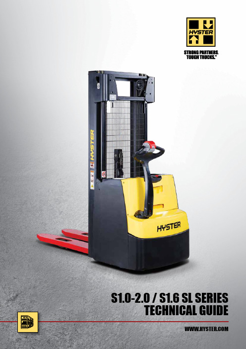
S1.0-2.0 / S1.6 SL SERIESTECHNICAL GUIDETRUCK DIMENSIONSS1.0 / S1.2 / S1.41-11-245FORK TABLES2 STAGE MASTFork length (1) Wheelbase Turning radius (3)Distance between fork-arms Length to face of forks (2) (3)Overalllength (3)Loaddistance (1) Load dimensionsAisle width (3)l (mm)y (m) Wa (mm)b 5 (mm)l 2 (mm)l 1 (mm)x (mm)l 6 (mm)b 12 (mm)pallet position Ast (mm S 1.2 | S 1.4 (250A H )80010591377520/570/68078315834491000800crossways 2258800800lengthwise 2109100012591464520/570/680783178364910001000crossways 22751000800lengthwise 2196115012591464520/570/680783193364910001200crossways 23591200800lengthwise 2345140014591764520/570/680783218384910001400crossways 26801400800lengthwise 2645160014591764520/570/680783238384910001600crossways 27781600800lengthwise2815Fork length (1) Wheelbase Turning radius (3)Distance between fork-arms Length to face of forks (2) (3)Overalllength (3)Loaddistance (1) Load dimensionsAisle width (3)l (mm)y (m) Wa (mm)b 5 (mm)l 2 (mm)l 1 (mm)x (mm)l 6 (mm)b 12 (mm)pallet position Ast (mm S 1.2 | S 1.4 (250A H )80010591377520/570/68082616264061000800crossways 2293800800lengthwise 2138100012591464520/570/680826182660610001000crossways 23011000800lengthwise 2225115012591464520/570/680826197660610001200crossways 23821200800lengthwise 2380140014591764520/570/680826222680610001400crossways 26901400800lengthwise 2680160014591764520/570/680826242680610001600crossways 27871600800lengthwise28533 STAGE MASTFork length (1) Wheelbase Turning radius (3)Distance between fork-arms Length to face of forks (2) (3)Overalllength (3)Loaddistance (1) Load dimensionsAisle width (3)l (mm)y (m) Wa (mm)b 5 (mm)l 2 (mm)l 1 (mm)x (mm)l 6 (mm)b 12 (mm)pallet position Ast (mm S 1.4 (375A H ) | S 1.680011311441520/570/68072815284491000800crossways 2322800800lengthwise 2173100013311533520/570/680728172864910001000crossways 23441000800lengthwise 2265115013311533520/570/680855200564910001200crossways 24281200800lengthwise 2414140015311829520/570/680728212884910001400crossways 27451400800lengthwise 2709160015311829520/570/680728232884910001600crossways 28431600800lengthwise28792 STAGE MASTFork length (1) Wheelbase Turning radius (3)Distance between fork-arms Length to face of forks (2) (3)Overalllength (3)Loaddistance (1) Load dimensionsAisle width (3)l (mm)y (m) Wa (mm)b 5 (mm)l 2 (mm)l 1 (mm)x (mm)l 6 (mm)b 12 (mm)pallet position Ast (mm S 2.080011311441520/570/68072815284491000800crossways 2322800800lengthwise 2173100013311533520/570/680728172864910001000crossways 23441000800lengthwise 2265115013311533520/570/680855200564910001200crossways 24281200800lengthwise2414Fork length (1) Wheelbase Turning radius (3)Fork carriage width Length to face of forks (2) (3)Overall length (3)Loaddistance (1) Load dimensionsAisle width (3)l (mm)y (m) Wa (mm)b 3 (mm)l 2 (mm)l 1 (mm)x (mm)l 6 (mm)b 12 (mm)pallet position Ast (mm S 1.6 S L80012081510800/1000/120072815284461000800crossways 2393800800lengthwise 224495014081607800/1000/1200728167864610001000crossways 24201000800lengthwise 2341115014081607800/1000/1200935208564610001200crossways 25041200800lengthwise 2490140016081899800/1000/1200728212884610001400crossways 28151400800lengthwise 2782160016081899800/1000/1200728232884610001600crossways 29131600800lengthwise2952Fork length (1) Wheelbase Turning radius (3)Fork carriage width Length to face of forks (2) (3)Overall length (3)Loaddistance (1) Load dimensionsAisle width (3)l (mm)y (m) Wa (mm)b 3 (mm)l 2 (mm)l 1 (mm)x (mm)l 6 (mm)b 12 (mm)pallet position Ast (mm S 1.6 S L80012081510800/1000/120097817784031000800crossways 2429800800lengthwise 227495014081607800/1000/1200978192860310001000crossways 24451000800lengthwise 2371115014081607800/1000/1200978212860310001200crossways 25261200800lengthwise 2526140016081899800/1000/1200978237880310001400crossways 28261400800lengthwise 2817160016081899800/1000/1200)978257880310001600crossways 29231600800lengthwise29908MAST INFORMATION2 STAGE NFL3 STAGE FFLLift height h 3 (mm)Free lift h 2 (m)Height, mast lowered h 1(mm) (1)Height, mast extended h 4(mm) (2)Weight of the mast(kg) (3)S 1.2 | S 1.4 | S 1.6S 1.0274014181850 (4)3268341294015181950 (4)3468354314016182050366836733401718215038683803540181822504068393374019182350426840639402018245044684194140211825504668432Lift height h 3 (mm)Free lift h 2 (m)Height, mast lowered h 1(mm) (1)Height, mast extended h 4(mm) (2)Weight of the mast(kg) (3)S 1.6S 1.4404013181850 (4)4606462434014181950 (4)4906481462015182050518649949001618215054665185180171822505746537546018182350602655657401918245063065756020201825506586594Lift height h 3 (mm)Free lift h 2 (m)Height, mast lowered h 1(mm) (1)Height, mast extended h 4(mm) (2)Weight of the mast(kg) (3)S 2.0260010019003172327280010020003372340300010021003572353320010022003772366340010023003972379360010024004172393380010025004372406400010026004572419Lift height h 3 (mm)Free lift h 2 (m)Height, mast lowered h 1(mm) (1)Height, mast extended h 4(mm) (2)Weight of the mast(kg) (3)S 1.2404013181850 (4)4606462434014181950 (4)490648146201518205051864994900161821505466518Lift height h 3 (mm)Free lift h 2 (m)Height, mast lowered h 1(mm) (1)Height, mast extended h 4(mm) (2)Weight of the mast(kg) (3)S 1.6 S L404013181850 (4)4606462434014181950 (4)49064814620151820505186499490016182150546651851801718225057465375460181823506026556STANDARD AND OPTIONAL EQUIPMENTPlease refer to the Price List for full option configurations.Other options available through Special Products Engineering Department (SPED). Contact Hyster for details.BATTERIES Vertical Battery Extraction MODEL TABLE NOTES:Specifications are affected by the condition of the vehicle and how it is equipped, as well as the nature and condition of the operating area. Inform your dealer of the nature and condition of the intended operating area when purchasing your Hyster ® truck.(1) With 3 stage mast: - 43mm (2) With 3 stage mast: +43mm;with 3 stage mast with load backrest: +43mm; with 2 stage mast with load backrest: +27mm.(3) These values may vary of +/-5%.(4)Available batteries 24V / 150Ah (144 kg) ; 24V / 150Ah Polypropylene case version (125 kg) ; 24V / 200Ah Polypropylene case version (160 kg) ; 24V / 100Ah Li-Ion (144 kg) ; 24V / 200Ah Li-Ion (154 kg) .(5) Available battery 24V / 210Ah (212 kg) ; 24V / 250Ah Polypropylene case version (180 kg + ballast 32 kg ) ; 24V / 200Ah Li-Ion (211 kg).(6)Available battery 24V / 210Ah (212 kg) ; 24V / 315Ah (288 kg) ; 24V / 375Ah (288 kg) ; 24V / 250Ah Polypropylene case version (180 kg + ballast 32 kg ) ; 24V / 200Ah Li-Ion (211 kg) ; 24V / 300Ah Li-Ion (277 kg) ; with 315/375Ah the wheelbase is increased y=+72 mm.(7) Available battery 24V / 315Ah (288 kg) ; 24V / 300Ah Li-Ion (277 kg).(8)Available battery 24V / 210Ah (212 kg) ; 24V / 200Ah BS (185 Kg) the battery isnot Din B ; 24V / 200Ah Li-Ion (154 kg) ; 24V / 200Ah Li-Ion (211 kg) ; with BS200Ah the wheelbase is decreased y=-62 mm.(9) With forks 1400/1600mm: +14 kg.(10) Available b 5 680 mm: with b 5 680mm, x -43mm, l 1 and l 2 +43mm.(11)Available battery 24V / 210Ah (212 kg) ; 24V / 315Ah (288 kg) ; 24V / 375Ah (288 kg) ; 24V / 200Ah Li-Ion (211 kg) ; 24V / 300Ah Li-Ion (277 kg) ; with 315/375Ah the wheelbase is increased y=+72 mm.(12) Value referred to S3 6%.(13) Value referred to S3 12%.(14) With 2 stage mast and b 5=570mm the s dimension increases 5mm for first 250mm at toe.16)Available battery 24V / 315Ah (288 kg).MAST INFORMATION TABLE NOTES:(1) With free lift of 100mm for NFL mast.(2) With load backrest (h=1000) for carriage: h 4 + 562mm (2 stage mast), +524mm (3 stage mast), + 518 mm (S2.0 2 stage mast).(3) All weights are: mast structures (weldment, cylinders, chain, pulley) + oilEXCLUDED: forks, accessories.(4) Not available with vertical extraction of battery BS200Ah.PRODUCT FEATURESDEPENDABILITYn R obust chassis design with a one-piece base frame (no welded arms) and a new pressed bumper.n B umper has increased thickness of 5mm and has been designed with rounds that improve both the protection of the operator’s foot and the robustness.n B attery covers are made of thick injection moulded Polycarbonate.n D ual processors controller for increased reliability.PRODUCTIVITYn T he Hyster traction motor gives powerful acceleration and has an increased travel speed of up to 6km/h.n F ull AC infrastructure on motor allows seamless changes indirection of travel, increasing cycle speeds and the control of pallet handling operations.n S traddle leg model is designed with bolted on legs (adjustable to three differend dimensions) to suit requirements of different applications: lifting bottom closed pallets or wider than EURO pallets and in special applications involving rotating clamps or clamps with extra hydraulic ways.ERGONOMICSn T iller arm is mounted in a mid height offset position with areduced operating space to offer low effort steering and better functions controllability.n T iller head with angled left- and right-hand grips and large butterfly buttons incorporates proportional lift and lowering controls within easy reach.n M ast incorporates Hyster designed profiles that reduce the total mast channel width and lift cylinder position optimized to increase operator visibility.n I nstrument panels are placed in reachable position and designed to house both Key or Keypad with the same layout and cover.n T he battery cover is designed to incorporate object holder although it has a wide sloped central plane to increase forks visibility.LOW COST OF OWNERSHIPn T he Hyster 1.2 kW traction motor gives powerful acceleration and an increased travel speed for superior performance and increased productivity.n A mong the lowest energy consumption in market makes Pedestrian Stacker one of the most cost effective solutions.n T he battery cover protects the battery from falling objects while the emergency switch is still visible from all angles.n D ash mounted display can show alarms, digital battery indicator and hourmeter.n H igh level of parts commonality with other Hyster products with proven reliability and durability for ease of maintenance.SERVICEABILITYn G reased for life load rollers in mast design.n D isplay provides error codes, battery status and hour-meter.n S ervice access level by laptop and standardized Hyster service cable.n T roubleshooting via CAN and via Display.n S ervice interval hydraulic oil and filter: 3000h or 3 years.n S tandard warranty – 24 monthsThe tough Hyster ® Pedestrian Stacker is designed for stacking and retrieving loads at low and medium lift heights and horizontal load transfer over short and medium travel distances. It has excellent manoeuverability, control and visibility.The all-new Pedestrian Stacker is built with the quality hallmarks of Hyster: tough, intelligent, dependable and efficient. Safety: This truck conforms to the current EU requirements.Specification data is based on VDI 2198.FORKS TABLE NOTES:(1) 2 stage mast only: less 27 mm with a load backrest fitted(2) 2 stage mast only: add 27 mm with a load backrest fittedBold values are reference versionNot all versions shown in tables are available as standard optionSTANDARD AND OPTIONAL EQUIPMENT TABLE NOTES:X Standart equipment 0 Optional equipmenrt -Not availableNOTICE:Care must be exercised when handling elevated loads. Operators must be trained and must read, understandand follow the instructions contained in the Operating Manual.All values are nominal values and they are subject to tolerances. For further information, please contact the manufacturer.Hyster products are subject to change without notice.Lift trucks illustrated may feature optional equipment. Values may vary with alternative configurations.www.hyster.eu*********************/HysterEurope@HysterEurope/HysterEuropeSTRONG PARTNERS. TOUGH TRUCKS.TMFOR DEMANDING OPERATIONS, EVERYWHERE.Hyster ® supplies a complete range of warehouse equipment, IC and electric counterbalanced trucks, container handlers and reach stackers. Hyster ® is committed to being much more than a lift truck supplier.Our aim is to offer a complete partnership capable ofresponding to the full spectrum of material handling issues: whether you need professional consultancy on your fleet management, fully qualified service support, or reliable parts supply, you can depend on Hyster ®.Our network of highly trained dealers provides expert, responsive local support. They can offer cost-effective finance packages and introduce effectively managedmaintenance programmes to ensure that you get the best possible value. Our business is dealing with your material handling needs so you can focus on the success of your business today and in the future.HYSTER-YALE UK LIMITED trading as Hyster Europe. Registered Address: Centennial House, Building 4.5, Frimley Business Park, Frimley, Surrey GU16 7SG, United Kingdom.Registered in England and Wales. Company Registration Number: 02636775.©2019 HYSTER-YALE UK LIMITED, all rights reserved. HYSTER, , and STRONG PARTNERS. TOUGH TRUCKS. are trademarks of HYSTER-YALE Group, Inc.NDIIThane, RedThane and Dynaroll are a trademarks of Wicke GmbH + Co. KG. Lexan is a trademark of Sabic Global Technologies B.V . Hyster products are subject to change without notice. Forklift trucks illustrated may feature optional equipment.Printed in EU. Part number: 3990791 Rev. 03-04/19-TLCHYSTER EUROPECentennial House, Frimley Business Park, Frimley, Surrey, GU16 7SG, England.Tel: +44 (0) 1276 538500。
ECAT-2094S EtherCAT 4 轴步进马达控制器 驱动器 使用手册说明书
ECAT-2094SEtherCAT4軸步進馬達控制器/驅動器使用手冊(Version 1.2.2)承諾鄭重承諾: 凡泓格科技股份有限公司產品從購買後,開始享有一年保固,除人為使用不當的因素除外。
責任聲明凡使用本系列產品除產品品質所造成的損害,泓格科技股份有限公司不承擔任何的法律責任。
泓格科技股份有限公司有義務提供本系列產品詳細使用資料,本使用手冊所提及的產品規格或相關資訊,泓格科技保留所有修訂之權利,本使用手冊所提及之產品規格或相關資訊有任何修改或變更時,恕不另行通知,本產品不承擔使用者非法利用資料對第三方所造成侵害構成的法律責任,未事先經由泓格科技書面允許,不得以任何形式複製、修改、轉載、傳送或出版使用手冊內容。
版權版權所有 © 2017 泓格科技股份有限公司,保留所有權利。
商標文件中所涉及所有公司的商標,商標名稱及產品名稱分別屬於該商標或名稱的擁有者所持有。
聯繫我們如有任何問題歡迎聯繫我們,我們將會為您提供完善的咨詢服務。
Email:******************,************************Contents1產品概述 (3)1.1簡介 (3)1.2技術數據 (4)1.3硬體規格 (5)1.4外型尺寸 (6)2供貨範圍 (7)3接線 (9)3.1LED燈定義 (9)3.2連接介面 (11)3.3數位輸入與輸出接線 (14)3.4步進馬達接線 (17)3.4.1 四線式馬達 (17)3.4.2 八線式馬達 (18)3.4.3 編碼器接線 (19)4基礎通訊 (22)4.1EtherCAT 佈線 (22)4.2狀態機 (22)4.3同步模式 (24)4.3.1 自由運行模式 (24)4.3.2 DC同步模式 (25)5專案整合 (28)5.1ESI 檔案 (28)5.1.1 匯入 ESI檔案 (28)5.2安裝與設定 (29)5.2.1 掃描EtherCAT裝置 (29)5.2.2 EtherCAT從站進程數據設定 (31)5.2.3 基本步進驅動器配置 (32)6位置控制設定 (35)6.1位置介面類型 (35)6.2Positioning Interface (35)6.2.1 加減速單位定義 (44)6.2.1.1從Vmin 到 Vma x的加速時間 (45)6.2.1.2從Vmin 到 V t a rget的加速時間 (46)6.2.1.3加速度[128*微步/秒2] (48)6.2.1.4從Vcurrent 到 Vtarget的加速時間 (49)6.2.2 加速度/減速度類型 (50)6.2.2.1Start-Stop Phase Type (50)6.2.2.2Standard Acceleration/Deceleration (52)6.3Positioning Interface Compact (52)6.4Position Control (57)7速度控制設定 (61)8CoE介面 (64)8.1概述 (64)8.2儲存設置數據到記憶體 (65)8.3驅動器調適 (68)9物件描述與參數化 (70)9.1標準物件 (70)9.2RxPDO Mapping Objects (71)9.3TxPDO Mapping Objects (73)9.4Sync Manager Objects (78)9.5Input Data (82)9.6Output Data (84)9.7Configuration Data (87)9.8Driver Tuning Functions (92)9.9Information and Diagnostic Data (93)9.10Configuration Parameters Storage (94)10錯誤列表 (95)11供應商特定暫存器定義 (96)1產品概述1.1簡介ECAT-2094S步進馬達控制器是一款高效且經濟實惠的兩相雙極步進驅動器,可同時控制最多4個步進馬達。
扭矩校验仪操作规程(3篇)
第1篇一、概述扭矩校验仪是一种用于检测和校准扭矩扳手、螺丝刀等工具扭矩值的精密仪器。
为确保操作人员的安全及仪器的准确度,以下为扭矩校验仪的操作规程。
二、操作步骤1. 准备工作(1)检查仪器外观,确保无损坏,电源线、信号线等连接正常。
(2)将扭矩校验仪放置在平稳、水平的桌面上,确保仪器稳定。
(3)连接电源线,打开仪器电源开关。
2. 校准(1)预热:打开仪器电源后,预热5-10分钟,使仪器达到稳定状态。
(2)校零:按仪器操作手册中所述方法进行校零,确保显示值为0。
3. 测量(1)选择合适的扭矩扳手或螺丝刀,插入校验仪的测量端口。
(2)根据待测扭矩值,调整仪器量程,确保待测扭矩值在量程范围内。
(3)缓慢施加扭矩,观察仪器显示值,当显示值达到设定扭矩值时,停止施加扭矩。
(4)重复测量3-5次,取平均值作为最终扭矩值。
4. 数据处理(1)将测量结果记录在测量记录表上。
(2)根据实际需求,将测量结果转换为其他单位(如N·m、kgf·cm等)。
(3)对测量结果进行分析,评估扭矩扳手或螺丝刀的准确性。
5. 关闭仪器(1)关闭仪器电源开关。
(2)断开电源线和信号线。
(3)整理工作台,清理工具。
三、注意事项1. 操作过程中,确保扭矩校验仪稳定放置,避免振动和倾斜。
2. 在施加扭矩时,注意力度均匀,避免瞬间过载。
3. 测量过程中,注意观察仪器显示值,确保准确记录。
4. 定期对扭矩校验仪进行校准,确保仪器准确度。
5. 严禁将扭矩校验仪用于超出量程范围的扭矩测量。
6. 操作人员应熟悉仪器操作规程,确保安全使用。
7. 仪器使用完毕后,及时关闭电源,断开电源线和信号线。
四、维护保养1. 定期检查仪器外观,确保无损坏。
2. 清洁仪器表面,保持仪器清洁。
3. 定期检查电源线、信号线等连接,确保连接正常。
4. 定期对仪器进行校准,确保仪器准确度。
5. 按照仪器操作手册进行维护保养,延长仪器使用寿命。
本规程适用于所有扭矩校验仪的操作,具体操作方法请以仪器操作手册为准。
长航力限器使用说明书

4.1.显示器部件说明 ······································································ 8 4.1.1 预警信号指示灯 ······························································ 10 4.1.2 超载信号指示灯 ······························································ 10 4.1.3 条形码(力矩百分比指示) ···················································· 10 4.1.4 操作按键 ········································································ 10 4.1.5 LCD 液晶显示器 ······························································· 11 4.1.6 蜂鸣器 ··········································································· 12 4.1.7 解除开关 ········································································ 12 4.1.8 工况选择拨码开关 ··························································· 12 4.1.9 臂长选择拨码开关 ··························································· 12 4.1.10 性能标牌 ······································································ 13 4.1.11 连接电缆 ······································································· 13
氪斯特H4.0-5.5FT系列堵车舱机技术指南说明书
H4.0-5.5FT SERIES TECHNICAL GUIDETRUCK DIMENSIONS3Maximum fork height h 3 + s (mm)Mast tilt (°)Lowered height h 1 (mm)Extended heighth 4 (mm)Free lift height h 2 + s (m)Superelastic tyresRadial tyresWithout sideshift (kg)With ISS (kg)Without sideshift (kg)With ISS (kg)H4.0FT6H4.0FT6H4.0FT6H4.0FT6F B w/o LB w LB w/o LB 600 LC 700 LC 600 LC 700 LC 600 LC 700 LC 600 LC 700 LC 2-S T A G E L I M I T E D F R E E L I F T30506°10°2175381543001504000389040003770400038904000377036506°10°2475441549001504000387040003750400038704000375042506°10°2775501555001504000386040003740400038604000374049506°6°322557156200150389037203890361038903720389036102-S T A G E F U L L F R E E L I F T 30756°10°21753890432513554000375040003690400037504000369036756°10°2475449049251655400037303990367040003730399036703-S T A G E F U L L F R E E L I F T 44156°6°21755225566513554000372039503640400037203950364049506°6°237557656200155538803600382035203880*3600*3820*3520*52506°6°247560656500165538103530374034503810*3520*3740*3440*55506°6°257563656800175537403450366033703740**3450**3660**3370**60006°6°277568157250195536203330353032503620**3330**3530**3250**Maximum fork height h 3 + s (mm)Mast tilt (°)Lowered height h 1 (mm)Extended heighth 4 (mm)Free lift height h 2 + s (m)Superelastic tyresRadial tyresWithout sideshift (kg)With ISS (kg)Without sideshift (kg)With ISS (kg)H4.5FTS5H4.5FTS5H4.5FTS5H4.5FTS5F B w/o LB w LB w/o LB 500 LC 600 LC 700 LC 500 LC 600 LC 700 LC 500 LC 600 LC 700 LC 500 LC 600 LC 700 LC 2-S T AG E L I M I T E D F R E E L I F T 28006°10°22153730406516045004000389044404000377045004000389044404000377034006°10°25154330466516045004000387044204000375045004000387044204000375040006°10°28154930526516045004000386044104000374045004000386044104000374047006°6°32655630596516043803900373042603900362043803890373042603890361053006°6°3665623065651604230376035804090375034704230*3760*3570*4080*3750*3460*59006°6°4065683071651604040362034203900358033104040**3610**3410**3900**3580**3310**2-S T A G E F U L L F R E E L I F T 28256°10°221538104090123045004000386044104000374045004000386044104000374034256°10°25154410469015304500400038404390400037204500400038404390400037203-S T A G E F U L L F R E E L I F T41456°6°221551305415123045004000382043704000370045004000382043704000370050006°6°25155985626515304300382036304150381035204250*3820*3630*4150**3810**3520**53006°6°26156285656516304210375035604070373034504210**3750**3560**4070**3730**3450**Maximum fork height h 3 + s (mm)Mast tilt (°)Lowered height h 1 (mm)Extended heighth 4 (mm)Free lift height h 2 + s (m)Superelastic tyresRadial tyresWithout sideshift (kg)With ISS (kg)Without sideshift (kg)With ISS (kg)H4.5FT6H4.5FT6H4.5FT6H4.5FT6F B w/o LB w LB w/o LB 600 LC 700 LC 600 LC 700 LC 600 LC 700 LC 600 LC 700 LC 2-S T A G E L I M I T E D F R E E L I F T28006°10°2215373040651604500434045004210450043404500421034006°10°2515433046651604500433045004200450043304500420040006°10°2815493052651604500431045004180450043104500418047006°6°3265563059651604390418043904060439041804390406053006°6°36656230656516042504030423039104240*4020*4220*3900*59006°6°40656830716516041003860405037404080*3840*4030*3730*2-S T A G E F U L L F R E E L I F T 28256°10°22153810409012304500431045004180450043104500418034256°10°2515441046901530450042904500417045004290450041703-S T A G E F U L L F R E E L I F T41456°6°22155130541512304500427044904150450042704490415050006°6°251559856265153043104080429039604310*4070*4280*3950*53006°6°261562856565163042404000421038904230*3990*4200*3880*R A T E D L O A D (k g )STANDARD CARRIAGELoad centre - distance from front of forks to centre of gravity of load.Rated load - based on vertical mast.R A T E D L O A D (k g )10002004006008001000120014001600180015002000250030003500400045005000550060004.0t @ 5005.5t5.0t 4.5t @ 6004.5t @ 5004.0t @ 60010002004006008001000120014001600180015002000250030003500400045005000550060004.0t @ 5005.5t5.0t 4.5t @ 6004.5t @ 5004.0t @ 600SIDESHIFT CARRIAGELOAD CENTRE (mm)LOAD CENTRE (mm)MAST AND CAPACITY INFORMATIONRATED CAPACITIESH5.0FT RATED CAPACITY KG@ 600-700 MM LOAD CENTREH5.5FT RATED CAPACITY KG@ 600-700 MM LOAD CENTREMaximum fork height h 3 + s (mm)Mast tilt (°)Lowered height h 1 (mm)Extended heighth 4 (mm)Free lift height h 2 + s (m)Superelastic tyresRadial tyresWithout sideshift (kg)With ISS (kg)Without sideshift (kg)With ISS (kg)H5.5FT H5.5FT H5.5FT H5.5FT F B w/o LB w LB w/o LB 600 LC 700 LC 600 LC 700 LC 600 LC 700 LC 600 LC 700 LC 2-S T A G E L I M I T E D F R E E L I F T28006°10°2215373040651605500528055005130550052805500513034006°10°2515433046651605500526055005120550052605500512040006°10°2815493052651605500525055005100550052505500510047006°6°32655630596516053805110537049705380*5110*5370*4960*53006°6°36656230656516052304940519048005220*4930*5180*4790*59006°6°40656830716516050504750500046205050**4750**4990**4610**2-S T A G E F U L L F R E E L I F T 28256°10°22153810409012305500525055005100550052505500510034256°10°2515441046901530550052305500508055005230550050803-S T A G E F U L L F R E E L I F T41456°6°22155130541512305500521054905070550052105490507050006°6°251559856265153052905000526048605290*4990*5260*4860*53006°6°261562856565163052104920517047805210**4910**5170**4780**E N G I N E7-1Engine manufacturer / modelKubota / V3600 IDI-T7-2Engine power output according to ISO 1585kW 57.07-3Rated speedrpm 24007-3-1Engine torque @rpm (1/min)N-m 296 @ 16007-4Number of cylinders / displacement # / cm 3 4 / 36207-8Alternator outputAmps 807-10Battery voltage, rated capacity V / Ah 12 / 175E 8-1Drive control / transmission Type / #Hydrodynamic / Automatic PowershiftM I S C 10-1Operating pressure for attachments bar 0 - 15510-2Oil volume for attachments (10)l/min 83.310-3Hydraulic oil tank, capacity l 51.0 (H4.0-H4.5FTS5) / 67.8 (H4.5FT6-H5.5FT)10-4Fuel tank, capacityl79.0 (H4.0-H4.5FTS5) / 100.3 (H4.5FT6-H5.5FT)10-7Sound pressure level at the driver’s seat (11)Lpaz dB(A)81MODEL TABLE NOTES:Specifications are affected by the condition of the vehicle and how it is equipped, as well as the nature and condition of the operating area. Inform your dealer of the nature and condition of the intended operating area when purchasing your Hyster ® truck.(1) T op of forks(2) add 32mm with load backrest(3) Full suspension seat in depressed position(4) W/o load backrest, add 32mm with load backrest(5)“Stacking aisle width (lines 4.34 & 4.34.1 &4.34.2) are based on the V.D.I. standard calculation as shown on illustration. The British Industrial Truck Associationrecommends the addition of 100 mm to the total clearance (dimension a) for extra operating margin at the rear of the truck”(6) at 1.6 km/h(7) at 4.8km/h. Gradeability figures are provided for comparison of tractive performance,but are not intended to endorse the operation of the vehicle on the stated inclines. Follow instructions in the operating manual regarding operation on inclines.(8) to 15m(9) Battery ampere hour (Ah) nominal capacity ratings are estimated.(10) Variable (11) Variable(12) Lpaz, measured according to the test cycles and based on the weighting valuescontained in EN12053(13) Lwaz, Measured according to the test cycles and based on the weighting valuescontained in EN12053MAST CAPACITY TABLE NOTES:(1) With load backrest (2) Without load backrest* Wide Tread or Dual Drive Wheels Required ** Dual Drive Wheels RequiredSafety: This truck conforms to the current EU requirements.NOTICE:Care must be exercised when handling elevated loads. Operators must be trained and must read, understand and follow the instructions contained in the Operating Manual.All values are nominal values and they are subject to tolerances. For further information, please contact the manufacturer.Hyster products are subject to change without notice.Lift trucks illustrated may feature optional equipment. Values may vary with alternative configurations.Fortens modelsSpecification data based on 3050mm (40/4.0 at 500 - 40/4.0 at 600) / 2800mm (45/4.5 at 500 - 55/5.5) TOF 2 stage LFL mast with standard carriage, 1000mm (40/4.0 at 500) / 1200mm (40/4.0 at 600 - 55/5.5) forks with manual hydraulics.Fortens Advance modelsSpecification data based on 3050mm (40/4.0 at 500 - 40/4.0 at 600) / 2800mm (45/4.5 at 500 - 55/5.5) TOF 2 stage LFL mast with standard carriage, 1000mm (40/4.0 at 500) / 1200mm (40/4.0 at 600 - 55/5.5) forks with e-hydraulics.Specification data is based on VDI 2198.H4.0FT5 FORTENS / FORTENS ADVANCE1-11-2H4.5FTS5 FORTENS / FORTENS ADVANCE1-11-2H5.0FT FORTENS / FORTENS ADVANCE1-11-2PERFORMANCE OPT Hyster FortensOPT HANDLING STD OPT Mechanical lever hydraulic controls, designed for clamping applications XTouchPoint™ mini lever hydraulic controls, designed forclamping applications X TouchPoint™ mini levers hydraulic control with Return to Set Tilt X TouchPoint™ mini levers hydraulic control with Return to SetTilt, designed for clamping applications X Auto Speed Hydraulics X3 Function (1 Auxiliary) Hydraulic Valve X4 Function (2 Auxiliary) Hydraulic Valve X 5th hydraulic function controlled by solenoid X Without Hose Group X Attachment Extension Tubes - 1 Pair X Attachment Extension Tubes - 2 Pair X Quick Disconnect Auxiliary Extension Tubes - 1 Pair X Quick Disconnect Auxiliary Extension Tubes - 2 Pair X 1220mm Carriage - Class 4X1220mm Integral Sideshift Carriage with Fork Positioner X 1370mm Hook Type Attachment Carriage - Class 3X 1372mm Attachment Carriage - Class 3X 1372mm Integral Sideshift Carriage with Fork Positioner X 1372mm Integral Sideshift Carriage - Class 4X 1524mm Carriage - Class 4X 1524mm Integral Sideshift Carriage - Class 4X 1525mm Integral Sideshift Carriage with Fork Positioner X Meyer Double Pallet Handler : 6-5207F a (EURO PALLETS) X Meyer Double Pallet Handler : 21PH32B-56SG-3A (CHEP/UK PALLETS)X 1220mm Load backrest X1000 x 120 x 50mm Hook Type Standard Taper Forks - Class 3(H4.0FT5)X1100 x 120 x 50mm Hook Type Standard Taper Forks - Class 3X 1200 x 120 x 50mm Hook Type Standard Taper Forks - Class 3(H4.0FT6)X1200 x 150 x 60mm Hook Type Standard Tapered Forks - Class 4(H4.05FT-5.5FT)X1300 x 150 x 60mm Hook Type Standard Taper Forks X 1400 x 120 x 50mm Hook Type Standard Taper Forks - Class 3X 1400 x 150 x 60mm Hook Type Standard Taper Forks X 1500 x 150 x 50mm Hook Type Standard Taper Forks - Class 3X 1500 x 150 x 60mm Hook Type Standard Tapered Forks - Class 4X 1600 x 150 x 50mm Hook Type Standard Taper Forks X 1600 x 150 x 60mm Hook Type Standard Taper Forks X 1800 x 150 x 50mm Hook Type Standard Taper Forks - Class 3X 1800 x 150 x 60mm Hook Type Standard Taper Forks X 2000 x 150 x 50mm Hook Type Standard Taper Forks X 2000 x 150 x 60mm Hook Type Stanard Taper Forks X 2200 x 150 x 60mm Hook Type Standard Taper Forks X 2400 x 150 x 60mm Hook Type Standard Taper Forks X LIFT STD OPT 2 Stage Limited Free Lift X2 Stage Full Free Lift XSTANDARD AND OPTIONAL EQUIPMENTOPTOPTOPTOPTERGONOMICS (continued)STD OPTFull Suspension Cloth Seat X Full Suspension Swivel Vinyl Seat X Full Suspension Swivel Cloth Seat X Heated Full Suspension Cloth Seat X High Backrest Lumbar Support Vinyl X High Backrest Lumbar Support ClothX Full Suspension FLM36 (Low Profile) Vinyl Seat X Full Suspension FLM36 (Low Profile) Cloth Seat X Grammer Air Suspension Vinyl Seat X Grammer Air Suspension Cloth Seat X Air-Suspension Seat FLA Vinyl Seat X Air-Suspension Seat FLA Cloth Seat X Standard Seat Belt XHi-Vis Red Seat BeltX Hi-Vis Red Seat Belt with InterlockX Hi-Vis Red Seat Belt with Sequential Interlock X Manual lever hydraulic controlsXTouchPoint™, mini lever hydraulic controlsTouchPoint™, mini lever hydraulic controls with clamping, hydraulic controlsX TouchPoint™, mini lever hydraulic controlswith Return to Set Tilt, hydraulic controlsX TouchPoint™, mini lever hydraulic controls with clamping and Return to Set Tilt, hydraulic controls X Joystick hydraulic controls X Steering wheel with spinner knob XSteering wheel without spinner knob X Directional Lever XMonotrolX Directional Control Switch (Integrated in Arm rest)X Dash Mounted 12V Auxiliary Power OutletXVISIBILITYSTD OPTHalogen work lights XLED work lightsX Work Light Package - 2 Front and 1 Rear Halogen Work Lights with Side, Stop, Tail, & Reverse LightsXWork Light Package - 2 Front and 1 Rear LED Work Lights with Side, Stop, Tail, & Reverse Lights X Automatic Lights X Mast Mounted LED Lights X LED Work Light ProtectionXOPERATIONSTD OPTImpact Monitor with 30 Second Shutdown X Impact Monitor with Immediate ShutdownXEngine, Lights and Display Shutdown (Seat Switch Activated)X Engine Shutdown (Seat Switch Activated)XSystem Monitoring System XPremium Monitoring System X Vented Hood X Non-Vented Hood XBelly PanX*Standard or Optional in select markets or on select models. Please refer to the Price List for full option configurations.Other options available through Special Products Engineering Department (SPED). Contact Hyster for details.STANDARD AND OPTIONAL EQUIPMENTOPERATION Visible alarm – Amber strobe lightPRODUCT FEATURESProtected PowertrainThe durable powertrain is computer controlled, protected and managed by the Pacesetter™ VSM electronic management system, featuring a CANbus communications network. The VSM ensures maximum uptime and dependability, asit allows for fast and accurate trouble-shooting, facilitates first-time fixes and can help to minimise costly “parts swapping”.DuraMatch TM - The World’sMost Advanced Powershift TransmissionThe electronically controlled DuraMatch™ transmissions provide smoother directional changesto eliminate shock loading and extend the life of the clutch packs. These transmissions offer unique and patented features, managed by the VSM, such as the Auto Deceleration System, which contributes to extending brake and tyre life and so reduces the frequency of required changes and ultimately your overall operating costs.Autospeed HydraulicsIf the Autospeed Hydraulics optionis selected when lifting a loadthe engine speed is automaticallyincreased to provide full hydraulicpower. The Pacesetter VSMmaintains the current travel speed(or prevents travel) until theoperator steps on the accelerator.No operator inching is requiredand productivity and efficiencyis increased by simplifyingoperator actions.Hassle-Free Electrical &Hydraulic SystemsThe CANbus system ensuresreliable operation of the truck,providing reduced wiringcomplexity and keeps them awayfrom heat sources. Non contactHall-Effect sensors and switchesare environmentally sealed toIP66 standards to keep out waterand debris (allowing the truck tobe pressure washable) and aredesigned to outlast the life of thetruck. The Hyster Fortens TM isequipped with hassle-free hydraulicsystems, featuring Leak-free O-ringface seal fittings which reduceleaks for enhanced reliability.More Dependable inDemanding ApplicationsAluminium core radiators and asuperior counterweight tunneldesign coupled with a “pusher”type fan provide the industry’s bestcooling, ensuring that the truckoperates at lower temperatures,which results in increasedcomponent life and limits the riskof overheating, particularly in heavyduty applications. In addition,the long term durability of hetruck is enhanced by the availablepowertrain protection systems.High-performance In-tankHydraulic FilterSuperior filtration systemincreases life span of all hydrauliccomponents such as hoses andpumps.Significant savings in ownershipcosts per lift truck – each yearThe Hyster Fortens TM has beendesigned to help you lower yourownership costs in all types ofapplications, through offeringa wide range of engine andtransmission options to suit theapplication need.As the first choice materials handling partner for the world’s demanding operations, Hyster delivers value added solutions and dependable products through the strongest distribution network in the industry Hyster Fortens TM - The Solution to your Application Needs.www.hyster.eu*********************/HysterEurope@HysterEurope/HysterEuropeSTRONG PARTNERS. TOUGH TRUCKS.TMFOR DEMANDING OPERATIONS, EVERYWHERE.Hyster ® supplies a complete range of warehouse equipment, IC and electric counterbalanced trucks, container handlers and reach stackers. Hyster ® is committed to being much more than a lift truck supplier.Our aim is to offer a complete partnership capable ofresponding to the full spectrum of material handling issues: whether you need professional consultancy on your fleet management, fully qualified service support, or reliable parts supply, you can depend on Hyster ®.Our network of highly trained dealers provides expert,responsive local support. They can offer cost-effective finance packages and introduce effectively managed maintenance programmes to ensure that you get the best possible value. Our business is dealing with your material handling needs so you can focus on the success of your business today and in the future.HYSTER-YALE UK LIMITED trading as Hyster Europe. Registered Address: Centennial House, Building 4.5, Frimley Business Park, Frimley, Surrey GU16 7SG, United Kingdom.Registered in England and Wales. Company Registration Number: 02636775.©2019 HYSTER-YALE UK LIMITED, all rights reserved. HYSTER, , STRONG PARTNERS. TOUGH TRUCKS., FORTENS, DURAMATCH, TOUCHPOINT and MONOTROL are trademarks ofHYSTER-YALE Group, Inc. Yanmar is a trademark of Yanmar Co. Ltd. Kubota is a trademark of Kubota Corporation. Continental is a trademark of Continental AG. Grammer is a trademark of Grammer Seating Systems Ltd. BOLZONI is a trademark of Bolzoni SpA. AURAMO is a trademark of Auramo Oy. MEYER is a trademark of Hans H. Meyer, GmbH.Hyster products are subject to change without notice. Forklift trucks illustrated may feature optional equipment.Printed in EU. Part number: 3990312 Rev. 03-01/19-TLCHYSTER EUROPECentennial House, Frimley Business Park, Frimley, Surrey, GU16 7SG, England.Tel: +44 (0) 1276 538500。
Omega Lift 4 Ton、5 Ton 和 10 Ton 长梯型搬运平台操作说明书
Long Chassis Hydraulic Service JacksSFA CompaniesSPECIFICATIONSModel Capacity Jack Size ( L x W x H)Min. Height Max. Height Hyd. Range Saddle Dia.22040C/ 22041C 4 Ton 50-5/8" x 15-3/8" x 7-1/2"5"24"19"5-1/2" 22050C/ 22051C 5 Ton 57-3/4" x 17" x 7-5/8"7"27"20"6-1/2" 22100C/ 22101C10 Ton54-3/4" x 20" x 12-3/4"7"27"20"7-3/8"SAFETY and GENERAL INFORMATIONSave these instructions. For your safety, read, understand, and follow the information provided with and on this jack before using. The owner and operator of this equipment shall have an understanding of this jack and safe operating procedures before attempting to use. The owner and operator shall be aware that use and repair of this product may require special skills and knowledge. Instructions and safety information shall be conveyed in the operator's native language before use of this jack is authorized. If any doubt exists as to the safe and proper use of this jack, remove from service immediately.Inspect before each use. Do not use if broken, bent, cracked or damaged parts are noted. Any jack that appears damaged in any way, or operates abnormally shall be removed from service immediately. If the jack has been or suspected to have been subjected to a shock load (a load dropped suddenly, unexpectedly upon it), immediately discontinue use until jack has been checked by a factory authorized service center (contact distributor or manufacturer for list of authorized service centers). It is recommended that an annual inspection be done by qualified personnel. Labels and Operator's Manuals are available from manufacturer.PRODUCT DESCRIPTIONOmega Long Chassis Hydraulic Service Jacks are designed to lift, but not support, one end of a vehicle. Immediately after lifting, loads must be supported by a pair of appropriately rated jack stands. Air actuated function available for Models 22041C, 22051C & 22101C. *************************************************************PSI air pressure is required to raise rated capacity load.NEVER use hydraulic jack as stand-alone device. After lifting, immediately support the lifted vehicle with ONE YEAR LIMITED WARRANTYFor a period of one (1) year from date of purchase, SFA Companies will repair or replace, at its option, without charge, any of its products which fails due to a defect in material or workmanship under normal usage. This limited warranty is a consumer's exclusive remedy.Performance of any obligation under this warranty may be obtained by returning the warranted product, freight prepaid, to SFA Companies Warranty Service Department, 10939 N. Pomona Ave., Kansas City, MO 64153. Except where such limitations and exclusions are specifically prohibited by applicable law, (1) THE CONSUMER'S SOLE AND EXCLUSIVE REMEDY SHALL BE THE REPAIR OR REPLACEMENT OF DEFECTIVE PRODUCTS AS DESCRIBED ABOVE. (2) SFA Companies SHALL NOT BE LIABLE FOR ANY CONSEQUENTIAL OR INCIDENTAL DAMAGE OR LOSS WHATSOEVER. (3) ANY IMPLIED WARRANTIES, INCLUDING WITHOUT LIMITATION THE IMPLIED WARRANTIES OF MERCHANTABILITY AND FITNESS FOR A PARTICULAR PURPOSE, SHALL BE LIMITED TO ONE YEAR, OTHERWISE THE REPAIR, REPLACEMENT OR REFUND AS PROVIDED UNDER THIS EXPRESS LIMITED WARRANTY IS THE EXCLUSIVE REMEDY OF THE CONSUMER, AND IS PROVIDED IN LIEU OF ALL OTHER WARRANTIES, EXPRESS OR IMPLIED. (4) ANY MODIFICATION, ALTERATION, ABUSE, UNAUTHORIZED SERVICE OR ORNAMENTAL DESIGN VOIDS THIS WARRANTY AND IS NOT COVERED BY THIS WARRANTY .Some states do not allow limitations on how long an implied warranty lasts, so the above limitation may not apply to you. Some states do not allow the exclusion or limitation of incidental or consequential damages, so the above limitation or exclusion may not apply to you. This warranty gives you specific legal rights, and you may also have other rights which vary from state to state.Always secure the handle into the handle sleeve by means of the bolt lock washer and nut provided. Tighten securely to prevent accidental removal of handle while in use.Before Use1. Verify that the product and application are compatible, if in doubt call Omega Technical Service (888) 332-6419.2. Before using this product, read the operator's manual completely and familiarize yourself thoroughly with theproduct, its components and recognize the hazards associated with its use.3. To familiarize yourself with basic operation, turn the release valve (handle knob):a. Clockwise until firm resistance is felt to further turning. This is the ‘CLOSED’ release valve position used toraise the saddle.b. Counter-clockwise, but no more than 1/2 turn from the closed position. This is the ‘OPEN’ release valveposition used to lower the saddle.4. With saddle fully lowered, locate and remove cover plate, then remove the oil filler plug/screw. Pump 6 to 8 fullstrokes. This will help release any pressurized air which may be trapped within the reservoir. Check oil level. Proper oil level will vary from just covering the ram cylinder to 3/16” above it as seen from the oil filler hole. Reinstall the oil filler plug/screw.5. For air option models 22041C, 22051C & 22101C, Pour a teaspoon of good quality, air tool lubricant into the air supplyinlet of the lift control valve. Connect to air supply and operate for 3 seconds to evenly distribute lubricant.Note: These models are equipped with the popular 1/4" NPT air coupler. When installing a different air coupler of your choice, ensure that thread tape or compound is used when servicing connections. To ensure dependable, trouble free operation an inline air dryer and oiler is recommended.6. Ensure that jack rolls freely. Raise and lower the unloaded saddle throughout the lifting range before putting intoservice to ensure the pump operates smoothly. Replace worn or damaged parts and assemblies with Omega authorized replacement parts only.Bleeding / Venting Trapped AirWith the release valve in the OPEN position (3b.) and with saddle fully lowered, locate and remove the oil filler plug/ screw. Pump 6 to 8 full strokes. This will help release any pressurized air which may be trapped within the reservoir. Reinstall the oil filler plug/screw.OPERATIONLifting Only attachments and/or adapters supplied by the manufacturer shall be used. Lift only on area of the vehicle as specified by the vehicle manufacturer.Note: The jack is equipped with handle position lock. To adjust the handle, release lock device by pulling the lever up, then back until lever is locked into place.1. Follow the vehicle manufacturer’s recommended guidelines for lifting. Engage the emergency brake and chock each unlifted wheel in both directions to prevent inadvertent vehicle movement.2. Locate and close the release valve by turning the release valve knob clockwise until firm resistance is felt.3. Refer to the vehicle manufacturer owner’s manual to locate approved lifting points on the vehicle. Center jack saddle under lift point.4. Verify lift point, then pump handle or foot pedal to contact lift point. To lift, pump handle or squeeze lift control valve (models 22041C, 22051C & 22101C) until load reaches desired height. Never use foot pedal to raise load.5. Transfer the load immediately to appropriately rated jack stands.NEVER use hydraulic jack as a stand alone device! ALWAYS transfer the lifted load IMMEDIATELY to a pair only! Do not exceed rated capacity.LoweringBe sure all tools and personnel are clear before lowering load. Slowly open the release valve! The more Maintain control of the rate of speed at which the load lowers at all times!1. Raise load high enough to clear the jack stands.2. Remove jack stands carefully. (always used in pairs).3. Slowly turn the release valve knob counter-clockwise, but no more than 1/2 full turn. If the load fails to lower: a. Use another jack to raise the vehicle high enough to reinstall jack stands. b. Remove the malfunctioning jack and then the jack stands. c. Use the functioning jack to lower the vehicle.4. After removing jack from under the vehicle, fully lower the saddle to reduce ram exposure to rust and contamination.MAINTENANCEImportant: Use ONLY good grade hydraulic jack oil. Avoid mixing different types of fluid and Never use brake fluid, turbine oil, transmission fluid, motor oil or glycerin. Improper fluid can cause failure of the jack and the potential for sudden and immediate loss of load. We recommend Mobil DTE 13M.Adding oil1. With saddle fully lowered set jack in its upright, levelposition. Locate and remove oil filler plug/screw. 2. Fill with oil until ~3/16" above the inner cylinder asseen from the oil filler hole. Reinstall the oil filler plug/screw.Changing oilFor best performance, replace the complete fluid supply at least once per year.1. With saddle fully lowered, remove the oil filler plug/screw.2. Lay the jack on its side and drain the fluid into asuitable container.Note: Dispose of hydraulic fluid in accordance with local regulations.3. Fill with oil until ~3/16" above the inner cylinder asseen from the oil filler hole. Reinstall the oil filler plug/screw. LubricationA periodic coating of light lubricating oil to pivot points, axles and hinges will help to prevent rust and assure that wheels, casters and pump assemblies move freely. To help ensure trouble free operation, an inline air dryer and oiler is recommended.CleaningPeriodically check the pump piston and ram for signs of rust or corrosion. Clean as needed and wipe with an oily cloth.Note: Never use sandpaper or abrasive material on these surfaces!StorageWhen not in use, store the jack with saddle fully lowered.REPLACEMENT PARTS(refer to page 6 thru12)Not all components of the jack are replacement items, but are illustrated as a convenient reference of location and position in the assembly sequence. When ordering parts, give Model number, serial number and parts description. Call or write for current pricing: SFA Companies, 10939 N. Pomona Ave. Kansas City, MO 64153, U.S.A. Tel:(888)332-6419 Fax:(816)891-6599 E-Mail:*******************Omega Website: TROUBLESHOOTINGSymptom Possible Causes Corrective ActionJack will not lift load• Release valve not tightly closed• Overload condition• Air pressure inadequate • Ensure release valve tightly closed • Remedy overload condition •Ensure adequate air pressureJack will lift, but not maintain pressure •Release valve not tightly closed• Hydraulic unit malfunction•Ensure release valve tightly closed• Discontinue use, contact Omegatechnical serviceJack will not lower after unloading• Reservoir overfilled• Linkages binding• Fluid level low • Drain fluid to proper level• Clean and lubricate moving parts • Ensure proper fluid levelPoor lift performance• Fluid level low•Air trapped in system • Ensure proper fluid level•With ram fully retracted, remove oil filler plug/screw to let pressurized air escape. Reinstall oil filler plug/ screwWill not lift to full extension• Fluid level low• Ensure proper fluid level4512345678911121342141516171819402123242526273031373839414344ABCDEFJ GIH Figure 2 - Replacement Parts Illustration for Model 22040C123456789111342141516171819402123242526273031373839414344AB CDEF JGIH1028293634323335Figure 3 - Replacement Parts Illustration for Model 22041CItem22040C Part#22041C Part#Description Qty 1G251-20008-000Filter1 2G423-20003-000Reservoir1 35905-00100-100Filler Plug1 45901-00071-000O-ring, D7.1x2.651 5G251-20004-000G250-20004-000Release Valve1 6G100-43000-000Hyd. Cartridge1 7B300-14002-000Washer1 8G651-31002-000Pump Cylinder1 9G651-31001-000Pump Piston1 10N/A G100-44000-000Hyd. Cartridge1 11G423-30000-000G423-70000-000Universal Joint1 12G251-00005-000N/A Spring1 135405-12039-000Pin1 145405-02028-000Retaining Pin2 15G423-40000-000Piston Link1 16G100-00015-000Return Spring, Pedal2 175102-06015-000Screw1 18G251-00009-000Foot Pedal1 19G251-00010-000Handle Fork1 21G423-00011-000Return Spring1 23G423-00013-000Saddle1 245111-55020-000Screw, Philips4 25G423-00010-000Cover1 26G251-40001-000Knob1 275402-04028-000Spring Pin128N/A A070-40009-000Hose clip1295110-04012-000Screw, Philips1 305110-05025-0005107-05016-000Screw1 31G423-20000-000G423-60000-000Hyd. Power Unit132N/A A20060-0006Air Hose133A27060-0003Air Motor1 34A20060-0007Lift Control Valve1 35A20060-0015Hose Assembly1 36A20060-0016Quick coupler, Male1 37G251-40000-000 G100-90009-K01Handle Assembly1 38G423-90004-K01Front Wheel Assembly2 39G250-90004-K02Caster Assembly2 40G250-90009-K03Bolt Assembly1 41G651-31000-000Pump Assembly1 425405-12050-000Pin1 435307-00012-000Washer2 445404-04030-000Retaining Pin2 455205-00005-000N/A Nut1 -G4230S-088 (includes 3,4 & A to J)Seal Kit for Hyd. Unit1-N/A A27010-0000Seal Kit for Air Motor1-A270-01100-0000Piston for Air Motor1 -22040C-L022041C-L0Label (s)--22040C-M0Manual-Replacement Parts List for Models 22040C & 22041C:Figure 4 - Replacement Parts Illustration for Model 22050C & 22051CReplacement parts illustration for Models 22050C & 22051C328ABCDEAFGIIHHJ214567891011121314151617181921202223242526272930313233343537383940(f or 22050C )(f or 22051C )414236Item Description Qty 3Filler Plug14O-ring, D7.1x2.651A O-ring, D116x42B O-ring, D73.8x3.51C Back-up Washer 1DU-cup1Seal Kit (G2501S-074)Contents:Replacement Parts List for Models 22050C & 22051C:Item DescriptionQty E Back-up Washer 1F O-ring, D53x51G Packing1H O-ring, D15x2.652I Back-up Washer2JPacking (for 22050C only)1Item 22050C 22051CDescription Qty 1G251-20008-000Filter12G250-20002-000Reservoir 135905-00100-200Filler Plug145901-00071-000O-ring, D7.1x2.6515G250-20004-000Release Valve 16G250-24000-000Hyd. Cartridge 17B300-14002-000Washer18G651-31002-000Pump Cylinder 19G651-31001-000Pump Piston 110G250-23000-000Hyd. Cartridge 111G250-30000-000Universal Joint 112G251-00005-000Spring 1135405-12036-000Pin2145405-02028-000Retaining Pin 215G250-50000-000Piston Link116G251-00004-000Return Spring, Pedal 1175110-06016-000Screw118G251-00009-000Foot Pedal 119G251-00010-000Handle Fork 1205304-00018-000Snap Ring 221G251-00003-000Return Spring 2225304-00028-000Snap Ring 223G251-00002-000Saddle1245110-06010-000Screw, Philips 425G250-00002-000Cover 126G251-40001-000Knob1275402-04028-000Spring Pin 128N/A A070-40009-000Hose clip1295110-04012-000Screw, Philips 1305105-05012-000Screw131G250-70000-000G250-20000-000Hyd. Power Unit 132N/A A20060-0006Air Hose 133A27060-0003Air Motor134A20060-0007Lift Control Valve 135A20060-0015Hose Assembly 136A20060-0016Quick coupler, Male 137G250-40000-000Handle Assembly138G250-90004-K01Front Wheel Assembly 239G250-90004-K02Caster Assembly 240G250-90009-K03Bolt Assembly 141G651-31000-000Pump Assembly 142G251-00007-000Handle Grip2-G2501S-074 ( includes 3,4 & A to J)Seal Kit for Hyd. Unit 1-N/AA27010-0000Seal Kit for Air Motor 1-A270-01100-0000Piston for Air Motor 1-22050C-L022051C-L0Label (s)--22040C-M0Manual-Figure 5 - Replacement Parts Illustration for Model 22100C & 22101CItem22100C22101C Description Qty 1G251-20008-000Filter1 2G100-40003-000Reservoir1 3G62S-03301-000Filler Screw1 45901-00071-000O-ring, D7.1x2.651 5G251-20004-000Release Valve1 6G100-43000-000Hyd. Cartridge1 7B300-14002-000Washer1 8G651-31002-000Pump Cylinder1 9G651-31001-000Pump Piston1 10G100-44000-000Hyd. Cartridge1 11G100-90009-K04Universal Joint1 135405-12039-000Pin2 145404-02028-000Retaining Pin2 15G100-70000-000Piston Link1 16G100-00015-000Return Spring, Pedal2 175402-05025-000Pin1 18G251-00009-000Foot Pedal1 19G251-00010-000Handle Fork1 205304-00018-000Snap Ring2 21G100-00014-000Return Spring1 225305-00024-000Snap Ring2 23G100-90009-K02Saddle Assy.1 245111-55022-000Screw, Philips4 25G100-00016-000Cover1 26G251-40001-000Knob1 275402-04028-000Spring Pin128N/A A070-40009-000Hose clip1295110-04012-000Screw, Philips1 305110-05025-000Screw1 31G100-80000-000G100-40000-000Hyd. Power Unit132N/A A20060-0006Air Hose133A27060-0003Air Motor1 34A20060-0007Lift Control Valve1 35A20060-0015Hose Assembly1 36A20060-0016Quick coupler, Male1 37G100-90009-K01Handle Assembly1 38G100-90004-K02Front Wheel Assembly2 39G661-70000-000Caster Assembly2 40G250-90009-K03Bolt Assembly1 41G651-31000-000Pump Assembly1 42G251-00007-000Handle Grip2 -G1001S-98G1000S-98Seal Kit for Hyd. Unit1-N/A A27010-0000Seal Kit for Air Motor1-A270-01100-0000Piston for Air Motor1 -22100C-L022101C-L0Label (s)--22040C-M0Manual-。
强威 4000磅调节式梁式吊车机所有者手册说明书

4000 lb. Adjustable Gantry CraneOwner’s ManualWARNING: Read carefully and understand all ASSEMBLY AND OPERATION INSTRUCTIONS before operating. Failure to follow the safety rules and other basic safety precautions may result in serious personal injury.Item #52523Thank you very much for choosing a Strongway™ product!For future reference, please complete the owner’s record below:Serial Number/Lot Date Code: ________________________________ Purchase Date: ____________________________________________ Save the receipt, warranty, and this manual. It is important that you read the entire manual to become familiar with this product before you begin using it.This Gantry Crane is designed for certain applications only. Northern Tool and Equipment is not responsible for issues arising from modification or improper use of this product such as an application for which it was not designed. We strongly recommend that this product not be modified and/or used for any application other than that for which it was designed.For technical questions, please call 1-800-222-5381.Intended Use (4)Technical Specifications (4)Important Safety Information (4)Safety Labels (6)Assembly Instructions (6)Operating Instructions (8)Maintenance (9)Parts Diagram (10)Parts List (11)Replacement Parts (11)Limited Warranty (12)The Gantry Crane is ideal for shops where heavy level lifting is essential.Capacity: 2 TonAdjustable Height: 7’ 11” - 11’ 9”Casters: 5”Assemble the crane loosely until the entire assembly is complete. Make certain that you have a large, clean, and uncluttered area for assembly. As the crane is large and heavy, you may have to lay out the different parts on their sides, and tighten and erect the entire assembly once complete.Step 1) Attach two Plates (#20) from two sides to the one end of the Crossbeam (#19). Secure with the four Bolts (#1), Washers (#2), Spring Washers (#3), and Nuts (#4). Repeat for theother end.Step 2) Attach each Inner Vertical Post Assembly to the Crossbeam (#19). Secure with the 8 Bolts (#1), Washers (#2), Spring Washers (#3), and Nuts (#4)Step 3) Attach the four Swivel Casters with Brake (#27) to the Base Assembly (#26). Apply grease to the zerk in each Caster.Step 4) Attach each Outer Vertical Post Assembly (#24) to each Base Assembly (#26), making certain that the slot at two sides of the Outer Vertical Post Assembly are facing theCasters’ direction. From the top, insert two (2) Bolts (#14) through the base of the OuterVertical Post Assembly, and into the Base Assembly (#26). Slip on the Washer (#2) andSpring Washer (#3) and secure by tightening the Nuts (#4).Step 5) Attach two Support Tubes (#22) to each Outer Vertical Post Assembly (#23). Insert the Bolt (#5) through the top of the Support Tube, and through the Eyelet. Slip on a Washer(#6) and Spring Washer (#7) and secure with the Nut (#8). Attach the other end of theSupport Tube to the Base Assembly with Bolts, Washers, Spring Washers, and Nuts.Repeat for all four Support Tubes.Step 6) Insert the Inner Vertical Post (#21) into the Outer Vertical Post (#23). Insert one (1) Pin of the Pins with Chain (part #18) through the slot and the Inner Vertical Post Hole so that itgoes all the way through to the other pin. Attach the Handle (#24) to the bracket on theside of Outer Vertical Post, insert the Bolt (#10) from the inside, slip on the Washer (#14)and Spring Washer (#15) and secure with the Nut (#11). Make sure the two (2) hooks ofthe Handle hold the two ends of the Pin (#18). Repeat for the other Post Assembly.Step 7) Tighten all the Bolts and Nuts securely and make certain that the entire assembly is tight and secure.Step 8) Test the crane according to manual and ANSI/ASME B30.17 standards.Step 1) Move the crane so that it is directly above the item to be lifted.Step 2) Securely fasten the item to the crane with the appropriate trolley or hoist.Step 3) Raising and lowering the Crossbeam requires two people. There is a Handle (#27) on each of the Outer Vertical Post Assemblies. To raise the Crossbeam, press the handle and theInner Vertical Post will be up by one hole, insert the other Pin into this hole to hold theposition. Pull out the original pin and hook the handle to the new positioned pin. Repeat toreach the height you need. The Inner Vertical Post Assembly has thirteen different stopping positions.# 52523 -2T∙For replacement parts and technical questions, please call Customer Service at 1-800-222-5381. ∙Not all product components are available for replacement. The illustrations provided are a convenient reference to the location and position of parts in the assembly sequence.∙When ordering parts, the following information will be required: item description, item model number, item serial number/item lot date code, and the replacement part reference number.∙The distributor reserves the rights to make design changes and or improvements to product lines and manuals without notice.Northern Tool and Equipment Company, Inc. ("We'' or '"Us'') warrants to the original purchaser only ("You'' or “Your”) that the Strongway product purchased will be free from material defects in both materials and workmanship, normal wear and tear excepted, for a period of one year from date of purchase. The foregoing warranty is valid only if the installation and use of the product is strictly in accordance with product instructions. There are no other warranties, express or implied, including the warranty of merchantability or fitness for a particular purpose. If the product does not comply with this limited warranty, Your sole and exclusive remedy is that We will, at our sole option and within a commercially reasonable time, either replace the product or product component without charge to You or refund the purchase price (less shipping). This limited warranty is not transferable.Limitations on the WarrantyThis limited warranty does not cover: (a) normal wear and tear; (b) damage through abuse, neglect, misuse, or as a result of any accident or in any other manner; (c) damage from misapplication, overloading, or improper installation; (d) improper maintenance and repair; and (e) product alteration in any manner by anyone other than Us, with the sole exception of alterations made pursuant to product instructions and in a workmanlike manner.Obligations of PurchaserYou must retain Your product purchase receipt to verify date of purchase and that You are the original purchaser. To make a warranty claim, contact Us at 1-800-222-5381, identify the product by make and model number, and follow the claim instructions that will be provided. The product and the purchase receipt must be provided to Us in order to process Your warranty claim. Any returned product that is replaced or refunded by Us becomes our property. You will be responsible for return shipping costs or costs related to Your return visit to a retail store.Remedy LimitsProduct replacement or a refund of the purchase price is Your sole remedy under this limited warranty or any other warranty related to the product. We shall not be liable for: service or labor charges or damage to Your property incurred in removing or replacing the product; any damages, including, without limitation, damages to tangible personal property or personal injury, related to Your improper use, installation, or maintenance of the product or product component; or any indirect, incidental or consequential damages of any kind for any reason.Assumption of RiskYou acknowledge and agree that any use of the product for any purpose other than the specifieduse(s) stated in the product instructions is at Your own risk.Governing LawThis limited warranty gives You specific legal rights, and You also may have other rights which vary from state to state. Some states do not allow limitations or exclusions on implied warranties or incidental or consequential damages, so the above limitations may not apply to You. This limited warranty is governed by the laws of the State of Minnesota, without regard to rules pertaining to conflicts of law. The state courts located in Dakota County, Minnesota shall have exclusive jurisdiction for any disputes relating to this warranty.Distributed by:Northern Tool & Equipment Company, Inc.Burnsville, Minnesota 55306Made in China。
简明操作指南- memoragraph m rsg45说明书

Products Solutions Services简明操作指南Memograph M RSG45高级数据管理仪本文档为《简明操作指南》;不得替代设备的《操作手册》。
设备的详细信息请参考《操作手册》和其他文档资料:所有设备型号均可通过以下方式查询:•网址:/deviceviewer•智能手机/平板电脑:Endress+Hauser Operations AppKA01177R/28/ZH/02.18714235132018-05-31Memograph M RSG452Endress+HauserMemograph M RSG45目录Endress+Hauser 3目录1文档信息 (4)1.1文档功能............................................................................41.2文档符号............................................................................41.3术语.............................................................................51.4注册商标............................................................................52基本安全指南 (5)2.1人员要求............................................................................52.2指定用途............................................................................52.3工作场所安全.........................................................................62.4操作安全............................................................................62.5产品安全............................................................................62.6台式机外壳型设备的安全指南(可选).....................................................62.7IT 安全.............................................................................63产品描述 (7)3.1产品设计 (7)4到货验收和产品标识 (7)4.1到货验收............................................................................74.2供货清单............................................................................74.3产品标识............................................................................74.4储存和运输..........................................................................85安装 (8)5.1安装条件............................................................................85.2安装测量设备........................................................................105.3安装后检查 (13)6电气连接 (14)6.1连接条件...........................................................................146.2接线说明...........................................................................146.3连接测量设备........................................................................156.4连接后检查.........................................................................257操作方式 (26)7.1操作方式概述........................................................................267.2测量值显示与操作单元.................................................................277.3通过现场显示访问操作菜单.............................................................307.4通过调试工具访问设备.................................................................308系统集成 (31)8.1在系统中集成测量设备 (31)9调试 (31)9.1功能检查...........................................................................319.2打开测量设备........................................................................319.3设置操作语言........................................................................319.4设置测量设备(“Setup”(设置)菜单)....................................................329.5访问保护和安全理念..................................................................389.6TrustSens 标定监测...................................................................39文档信息Memograph M RSG45 1 文档信息1.1 文档功能《简明操作指南》包含所有必要信息,从到货验收到初始调试。
Kinetix 5500 伺服驅動器使用手冊说明书

Kinetix 5500 伺服驅動器型號 2198-H003-ERS、2198-H008-ERS、2198-H015-ERS、2198-H025-ERS、2198-H040-ERS、2198-H070-ERS、2198-H003-ERS2、2198-H008-ERS2、2198-H015-ERS2、2198-H025-ERS2、2198-H040-ERS2、2198-H070-ERS2、2198-CAPMOD-1300本手冊連結至 Kinetix 5500 伺服驅動器故障碼參考資料,出版物2198-RD005,以供故障碼查詢。
立即下載試算表以離線存取。
2Rockwell Automation 出版品 2198-UM001L-ZC-P - 2022 年 2 月Kinetix 5500 伺服驅動器使用手冊使用者重要資訊進⾏本產品的安裝、設定、操作或維護前,請閱讀本文件及其他資源一節內有關本設備安裝、設定和操作的文件。
使用者除了必須瞭解所有相關法規、法律條文與標準外,還需熟知安裝與配線說明。
舉凡安裝、調整、運作、使用、組裝、拆卸及維護等作業,均需由受訓合格的⼈員依照相關法規進⾏。
若以製造商未提及之方式使用本設備,將可能損害到製造商為本設備所提供的保護措施。
不論任何情況,Rockwell Automation Inc. 對於使用或應用此裝置而產生的間接或連帶損壞,均不負擔任何法律或賠償責任。
本手冊中的範例和圖表皆僅供說明之用。
由於個別安裝會有許多不同的變數及條件,Rockwell Automation,Inc. 無法對依照範例及圖⽰指⽰進⾏的實際使用狀況負責或提供賠償。
關於本手冊中所述之資訊、電路、設備或軟體部分,Rockwell Automation Inc. 概不承擔任何專利責任。
在取得 Rockwell Automation Inc. 書面同意之前,禁止重製本手冊部分或全部內容。
在整本手冊中,我們會在必要時使用註記,讓您瞭解安全注意事項。
AEC AEC4900 智能型电机控制器 技术说明书
AEC智能型电机控制器型号:AEC4900技术说明书 VER:1002250American Electric Control Company目录一.概述 (3)1.1用途及适用范围 (3)1.2主要性能介绍 (3)1.3主要功能模块 (3)二.产品分类及订购说明 (4)2.1 控制器的功能配置 (4)2.2控制器的面板及端子布置 (5)2.3控制器的端子号定义 (7)2.4控制器的定购选型说明 (9)三. 安装 (11)3.1控制器的外形及安装尺寸(100A) (11)3.2控制器的外形及安装尺寸(250A) (11)3.3AEC4940显示模块外形尺寸 (12)3.4AEC4900手持编程器的外形尺寸 (12)3.5外部电流互感器ZT40的外形及安装尺寸 (13)3.6外部漏电互感器ZT30的外形及安装尺寸 (13)3.7控制器与各种模块间的连接方式 (14)四. 技术参数 (17)4.1符号对照表 (17)4.2测量显示误差 (17)4.3保护设定参数 (18)4.4各种保护特性说明 (20)4.4.1过负载保护4.4.2缺相不平衡保护4.4.3接地漏电保护4.4.4欠电流保护4.4.5 堵转保护4.4.6 过热保护4.4.7欠压保护4.4.8过压保护4.4.9 欠功率保护4.4.10 起动加速超时保护4.4.11 外部故障保护4.4.12 相序保护五、特殊控制功能说明 (25)5.1 外部停车5.2 上电延时自动重起动5.3 欠压或失压延时重起动5.4 远程就地控制权限AEC4900智能型电机控制器技术说明书一.总述1.1 用途和适用范围AEC4900系列智能型(电动机)控制器(以下简称控制器)。
该控制器用于操作交流50Hz,额定工作电压至660V,额定电流至250A交流电动机控制回路中的接触器,对电动机的过载、过热、外部故障、堵转、相序、缺相不平衡、欠压、过压、欠功率、接地或漏电等故障引起的危害予以保护,并有测量、操作控制、自我诊断、维护管理、总线通讯(遥测、遥讯、遥调、遥控)等功能。
工业网络用户使用手册(赫思曼)
工业网络用户使用手册(赫思曼)目录一、工程概况 (2)二、交换机参数 (4)2.1 核心交换机 (4)2.2 接入交换机 (6)2.3 防爆交换机电源接线原理 (7)2.4 交换机端口指示灯介绍 (8)2.4.1 MS4128交换机 (8)2.4.2 MACH 4002交换机 (12)三、系统调试 (12)3.1 配置注意事项 (12)3.2 交换机设置主要步骤 (13)3.3 具体配置 (13)3.3.1配置名称、IP地址 (13)3.3.2 利用IE浏览器设置交换机 (14)3.3.3 利用HiVision软件设置划分VLAN (32)3.3.4 网络管理 (48)四、设备日常监测维护 (56)4.1 线路监测 (56)4.2 设备检查 (56)4.3 检查路由的测试命令 (57)4.4 UPS维护 (57)4.5 蓄电池维护 (58)4.6 机房设备日常维护 (59)一、工程概况唐山煤矿工业网络主要负责人员定位系统以及后续建设系统的数据传输,整个传输平台采用国际领先的德国赫思曼公司的工业网络交换机建设。
由于唐山煤矿开采时间长,井下巷道复杂跨度大、距离远,分A、B两区。
在网络设计时,井下设计20台防爆MS4128接入交换机,结合实际情况暂安装16台,其它留作后期网络扩展。
具体安装位置如下:A区:902泵房、11水平泵房、12水平泵房;B区:502配电室、8号井车房配电室、5021变电硐、7070机头配电室、702配电室、8070机头配电室、905泵房、8050配电室、南三泵房配电室、岳胥区变电硐、12号井变电硐、十一横管变电硐、八横贯配电室。
结合实际情况,将井下网络分为3个千兆光纤环形网络,A区1个千兆环、B区两个千兆环,通过地面机房的两台核心交换机实现互连、互通。
具体环网结构拓扑如下图:唐山煤矿工业网络拓扑图二、交换机参数德国赫思曼工业以太网交换机在煤矿自动化系统中的应用最广泛、也是是目前全球工业以太网技术的领导者。
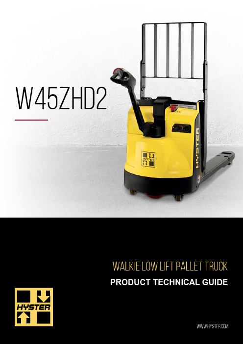
浩斯特(Hyster)W45ZHD2 10.0°低杆提升调节高架摆动卸货机产品说明书
W45ZHD2NOTE: Above specifications, unless otherwise listed, are for a standard truck without optional equipment. Right angle stack and equal intersecting aisle are calculated using a 40” wide pallet.CERTIFICATION: These Hyster ® lift trucks meet design specifications of Part II ANSI B56.1-1969, as required by OSHA Section 1910.178(a)(2) and also comply with Part III ANSI B56.1-revision in effect at time of manufacture. Certification of compliance with the applicable ANSI standards appears on the lift truck. Performance specifications are for a truck equipped as described under Standard Equipment on this Technical Guide. Performance specifications are affected by the condition of the vehicle and how it is equipped, as well as by the nature, condition of the operating area, proper service and maintenance of thevehicle. If these specifications are critical, the proposed application should be discussed with your dealer.RL = Rated load; NL = No load 1 Measured using a 42” x 40” pallet 2Measured using a 36” x 36” pallet 3Measured to the bottom of a GMA approved pallet on the forks while they are in the raised position 4With delivery moveable load backrest* Optional equipmentNotes: a) Battery size is limited by rounded corners of battery compartment. b) Cable lead position “B” c) 16” cable lengthd) Maximum cable gauge of 1/0FACTORY INSTALLED1 Measured using a 42” X 40” pallet 2Measured using a 36” X 36” pallet。
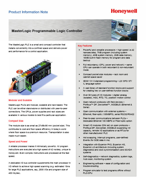
Honeywell MasterLogic PLC-H6000说明书
MasterLogic Programmable Logic ControllerThe MasterLogic PLC is a small and compact controller that installs conveniently into a confined space and delivers powerand performance for a control application.Modular and ScalableMasterLogic PLCs are modular, scalable and rack-based. The PLC can be either stand-alone or distributed with peer-to-peer connections. The CPUs, power supplies and rack sizes are available in various models to best fit a particular application.Compact SizeThe module size is as small as 27x98x90 mm (pocket size). This contributes to cost and floor space efficiency in today’s world where floor space is a premium resource. Transportation is also made much easier.Speed and PowerA reliable processor makes it intrinsically powerful. All program instructions are executed at a high speed of 42 ns/step, unique to Honeywell. Even complex instructions are processed at this fast speed.A dedicated I/O bus controller supplements the main processor in I/O refresh to achieve high speed scanning (e.g. estimated 15ms for large PLC applications, say, 2500 I/Os and program size of 400 Kbytes).Key Features•Powerful and versatile processors – high speed i.e.42 nanosec/step, 7MB program (including systemmemory), 4MB system memory, 2MB data memory, 16MB built-in flash memory for program and data backup•Full redundancy (CPU, power and network) – same CPU can operate in both redundant & non-redundant mode.• Compact pocket size modules – rack room and cabinet space saver• IEC61131-3 standard programming – LD/ SFC/ ST/ IL language option•A vast library of standard function blocks and support for creating new or user-defined function blocks • Over 50 types of I/O modules – digital/ analog (isolated), HSC, RTD, TC, position/ motion control •Open network protocols with field devices –Profibus™ DP, DeviceNet™, MODBUS (Ethernet & Serial)•Open communication with external systems –Ethernet, fiber-optic (100MBPS), serial RS232/RS422 • Peer-to-peer communications between PLCs –Dedicated Ethernet 100 MBPS or Fiber-optic option •Smart I/O modules (DIN rail) on open protocols – Profibus-DP, DeviceNet, MODBUS expanding I/O capacity, remote I/O applications or as RTUs for other manufacturers’ PLC• Hot swapping, Interrupt programs, user-defined Events (for SOE data in ms)• Integration with Experion PKS, Experion HS,Experion LS architecture (including systemdiagnostics and clock synchronization) and SCADA systems • Self-diagnostics – network diagnostics, system logs, Auto scan, monitoring system•Engineering software – ease of configuration and trouble-shooting•Program simulator to test programs offline without PLC/CPUCPU Specification Model : 2MLR-CPUH/T 2MLR-CPUH/FExecution speed 42 nano sec/stepProgram Memory (inc. SystemMemory)7MB Built-in Flash Memory 16MBData Memory 2MBMax rack I/O 23,808Max I/O using Network 128,000Max slots 372 slotsMax expansion 31 basesScan time (e.g. 2500 I/O, 400 Kbytesof program)15 millisecondsOpen Network StandardsIndustrial communication standards have continuously evolved and so has MasterLogic PLC’s interface capability with them. In addition to MODBUS (Ethernet and serial), MasterLogic supports other protocols such as Profibus™ DP, DeviceNet™, OPC DA server etc. Open standards network DeviceNet and Profibus devices, such as smart actuators, sensors, intelligent drives and transducers can be easily connected to MasterLogic. Its plug & play features and open standards support make them easily interoperable. On a physical level, Fast Ethernet, Fiber-Optic, RS232/ 422/ 485 communication links are directly supported. Versatile CPU•IEC61131-3 standard programming – LD/ SFC/ ST/ IL language option•MasterLogic allows for modularizing the entire program into max. 256 easily managed sub-programs, executed onceevery scan in the order. In addition, several interrupt driven programs are supported:Interrupt #program (max) RemarksTimer 32Internal Device 32 Memory variable•Flash memory (16MB) for program and data retention •Two built-in programming ports (USB@12MBPS and RS232C)•Built-in MODBUS slave RS232C communication port •Real Time Clock (RTC)•RUN/ STOP/ DEBUG mode of operation•Configurable address range of two latch areas for dataretention (non-volatile memory)•Self-diagnostics for system errors (memory, I/O, battery, power, execution, delays)•Direct I/O operation - IORF instruction for direct read/ write of I/O modules for time-sensitive applicationsOnline Maintenance and Trouble-Shooting•Hot-swapping of I/O modules through a software wizard or a CPU dip switch•Force I/O values (bit and word) for maintenance and trouble-shooting•Skip I/O of a selected I/O module or an entire I/O base •User-defined Event Recording (SOE) – digital devices can be configured for automatic event recording when falling,rising or COS (change of state) with millisec, and timestamp for SOE analysisThe PLC system alarm and event history is as follows: Type Condition SizeError Any error 2048 eventsMode RUN/STOP 1024 eventsPower change Power ON/OFF 1024 eventsSystem events Key system events 2048 eventsDigital I/O ModulesMasterLogic has a wide range of digital I/O modules: • 24V DC input modules (Sink source or source only type) • AC input modules (110V or 220V AC)• Relay, Triac, transistor ouput modules (sink or source) • 8, 16, 32, 64 points I/O module • Photo-coupler isolation • LED for module and input status• Easy maintenance: Terminal block type, one-touch installationof moduleAnalog I/O Modules• High speed A/D or D/A (250µs/ channel) conversion andprocessing • Channel to channel isolation • High resolution (16 bits) • Digital value in 4 data formats• Detection flags for input signal disconnect when analog inputrange is 1 ~ 5V or 4 ~ 20 mA. • LED status displays for RUN/ ERROR conditions • Voltage/ Current switching option • RTD (2-wire, 3-wire, 4-wire)• Thermo-couple (K, J, B, T, E, R, S, N, C types)Special Modules• 2-channel high speed counter (voltage input or differentialvoltage incremental encoder, preset function) • Positioning modules • Motion control moduleIf the field I/O signals are located too far away from theMasterLogic CPU the same I/O modules can also be used as remote I/O to reduce wiring costs and associated costs. Inaddition, it also significantly increases the overall I/O capacity of the MasterLogic PLC e.g. 23,808 to 128,000.Peer-to-Peer CommunicationsPeer-to-peer communication between PLCs is an important requirement in large inter-related control applications. A high speed Ethernet module at 100Mbps or optional fiber-optic module ensures fast and reliable integration between MasterLogic PLCs. Installation involves just a few simple configuration steps i.e. basic parameter, HS link item settings,etc.Integrated PLC Engineering EnvironmentSoftMaster provides the engineer with an integrated PLC engineering environment – all-in-one window such as ladder programming, configuration/ setup of CPU or other special/communication modules, debugging, monitoring, troubleshooting, documentation and maintenance, etc.Project FileSoftMaster helps manage multiple PLCs through a single window. One project file can include multiple PLCs from the site as central storage of all PLC details.MasterLogic RedundancyFor critical applications, eliminating all single points of failure in the system architecture ensures high availability. Redundancy features include:• CPU redundancy— Seamless switchover to standby CPUwithin 50ms when master fails without interrupting operations • Power supply redundancy for both CPU and I/O racks • Network redundancy — ring topology providing dualcommunication paths to I/O racks • High speed synchronization of program and data betweenprimary and backup CPU via dedicated fiber optic line • Built-in twisted pair or fiber-optic networks for local (100m)and remote I/O (2km) racks on ring topology • Base type remote I/O functionality• Base I/O capacity enhanced to 23,808 (372 slots in 31 bases)More InformationFor more information on MasterLogic PLC, visit /ps or contact your Honeywell account manager.Automation & Control SolutionsProcess SolutionsHoneywell2500 W. Union Hills Dr.Phoenix, AZ 85027Tel: +1-602-313-6665 or 877-466-3993 /psApplications•Process Industries: oil and gas, steel, cement, power generation, chemicals, petrochemicals• Automobileindustries•Food and Beverage•Healthcare and Pharmaceuticals• Textiles• Materialhandling• WaterTreatment• Semi-conductors•Printers and Publishers•Paints and Plastics•OEM – partnerships with packaged equipment manufacturers and machine builders Interface with Experion PKS, Experion HS, Experion LSMasterLogic PLCs are tightly integrated with the Experion architecture. They directly reside on the FTE or Ethernet network of Experion PKS and the Ethernet network of Experion HS and Experion LS, eliminating the need for any intermediate gateway equipment.•The interface supports configuring MasterLogic PLC channels, controllers and points just like any other SCADA interface•For efficient communication optimization, the integration supports both synchronous (timer based subscription of real time data) and asynchronous (change of state, report byexception) communication methods•All PLC clocks are synchronized with the Experion PKS server clock•PLC system alarms and events (e.g. battery fail, CPU STOP, RESET, ERROR) automatically cascade to Experionsummary page with acknowledgment, return to normalfunction etc•PLC system status (graphical display) monitoring from all Experion StationsPN-09-05-ENGApril 2009© 2009 Honeywell International Inc.。
力矩限制器用户手册

力矩限制器用户手册1、本产品适用于建筑用塔式起重机(平臂吊)•符合《GB12602-2009起重机械超载保护装置安全技术规范》•丰富的声光警示信息:预警/报警/保护/故障•具有超载、超大幅、超小幅等保护输出,禁止起重机在危险状态下的危险操作•可根据起重机操作档位信号自动切换对应的作业工况2、大屏幕LCD显示屏,显示清晰•采用5.7寸半透式图形LCD,分辨率320*240,自带背光。
强烈阳光直射和夜间,显示信息均清晰可见。
•背光亮度可调。
开启节电功能后,如果16秒无按键操作,自动关闭背光。
3、中/英文界面可选。
密码菜单设置调校,使用方便。
4、具有上电自检和传感器故障在线诊断功能,方便使用维护。
5、具有密码解除报警功能,以满足特殊情况的使用。
6、仪表(设备)编号设置,便于仪表的维护管理7、风速测量功能(选配)8、485接口,可。
连接扩展外设,增加功能工作电压: 110~240V AC 综合误差:≤±5%分辨率:重量0.1T/幅度0.1m 开关容量:AC250V/3A输出开关:3(4)个记录数量:500条整机功耗:﹤10W工作温度:﹣20℃~﹢60℃相对湿度:﹤95%(25℃)工作方式:连续防护等级:室外部件1P65室内部件IP541/14仪表系统由主/副等吊钩的称重传感器(视车型配置)、角传感器、仪表,及风速传感器(选配)构成。
在使用中,仪表会根据司机的操作档位自动切换为相应的工况参数,进行载荷、幅度/幅度的测量,并根据当前作业位置的额定载荷、幅度范围进行监控。
当设备接近或处于危险作业状态时给出相应的报警提示信息,当超出允许作业条件时发出控制信号,用于切断外部操作回路禁止危险方向的作业。
*注1:重量传感器2仅视测量需要选配*注2:风速传感器仅在配置有风速仪功能时,才需要*注3:高度传感器仅在需要时配置右图为仪表工作界面。
说明如下:.报警:黄色,状态如下:(1)故障:亮0.1s/灭1.2s,闪烁。
Cutler-Hammer E49金属限位开关安装说明说明书
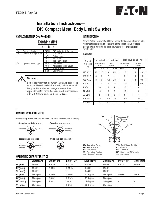
P50214 Rev 03Installation Instructions—E49 Compact Metal Body Limit SwitchesCATALOG NUMBER COMPONENTSINTRODUCTIONEaton’s Cutler-Hammer E49 Metal limit switch is a robust switch with high mechanical strength. Features of the switch include rugged diecast switch housing with oiltight, waterproof and dust-proof construction.E49M11AP1E49M11BP1E49M11CP1E49M11DP1E49M11UP1E49M11VP1 E49M11XM1OF (max.) 2.99 lb. 6.02 lb. 6.02 lb.0.31 lb. 2.99 lb.0.33 lb. 0.06 lb.RF (min.)0.50 lb. 2.01 lb. 2.01 lb.0.06 lb.0.50 lb.--TF (max.) 6.00 lb.--0.44 lb. 6.00 lb.--PT (max.)20 degrees 1.7mm 1.7mm 20 degrees 20 degrees 28mm 28mm OT (min.)30 degrees 6.4mm 5.6mm 30 degrees 30 degrees - -MD (max.)12 degrees 1mm 1mm 12 degrees 12 degrees - -TT (min.)50 degrees- 6.5mm50 degrees50 degrees- -OPERATING CHARACTERISTICSRATINGS125 VAC 1010 3 1.5 105 2.0250 VAC 5 5 2 1 53 1.0480 VAC 3 3 1.50.8 3 1.50.8600 VAC 1110.5 1.510.58 VDC 10 6 3 10 614 VDC 10 6 3 10 630 VDC6 4 3 6 4125 VDC 0.80.20.2 0.8 0.2250 VDC0.40.10.10.40.1Rated Voltage (V)Non-inductive Load (A)ResistanceLoad Lamp LoadN.C. N.O. N.C. N.O. N.C. N.O.N.C. N.O.Inductive Load (A)Inductive Load Motor Load “a”Product FamilyE49M E49 Metal Limit Switch “b”Contact Configuration11 1 N.O./1 N.C.AP1Roller Lever BP1Top PushCP1Top Push Roller DP1Rod LeverUP1Adjustable Roller Lever VP1Wobble Head XM1Cat Whisker“c”Operator Head Typedo so could result in electrical shock, serious personal injury, and/or equipment damage. Always followappropriate safety precautions and install in accordancewith U.S. National and local Electrical Codes.Relationship of the cam to operation (observed from the rear of switch )Operation on both sidesOperatesOperation on one sideDoes not operateOperation on one sideAvoid this combinationoperateCONTACT CONFIGURATIONOF: Operating Force RF: Return Force TF: Total ForceOP: Operating Position RP: Releasing PositionTTP: Total Travel Position PT: Pretravel OT: OvertravelMD: Movement Differential TT: Total TravelTTPP50214 Rev 03SPECIFICATIONSOperating Speed 1mm to 2 m/secOperating Frequency Mechanically: 120 operations/min.; Electronically: 30 operations/min.Contact Reistance 15m Ω max. (intial)Insulation Resistance 100M Ω min. (at 500 VDC)Dielectric Strength 1,000 VAC, 50/60Hz for 1 minute between non-continuous terminals; 2,200 VAC, 50/60 Hz for 1 minute between each terminal and non-current carrying metal part and between each terminal and ground Temperature Rise 50 degrees max.Vibration Malfunction durability: 10 to 55 Hz; 1.5 mm double amplitudeShockMechnical durability: approx. 1,000 m/sec 2 (approx. 100 G’s); Malfunction durability: approx. 300/sec 2 ( 30 G’s)Ambient TemperatureOperating: -50 to 80 degrees Celsius Humidity 95% RH max.Service LifeMechanically: 15,000,000 operations min; Electrically: 500,000 operations min.DIMENSION DIAGRAMS Top Push (E49M11BP1)Top Push Roller (E49M11CP1)Rod Lever (E49M11DP1)Adjustable Roller Lever (E49M11UP1)Wobble Head (E49M11VP1)Cat Whisker (E49M11XM1)Roller Lever (E49M11AP1)。
