动态系统模拟的方法共21页文档
汽车动力学仿真基础PPT课件

1.3、系统-三要素
实体 属性 活动
研究系统,就是研究系统状 态的变化,即研究系统的动 态特性和运动规律.
性能状态
系统状态
第14页/共44页
1.4、系统-分类
描述特性
连续系统:微分方程,差分方程 离散事件系统:逻辑条件,流程图
可以用有限个变量描
物数理学参结性述数的构质物系系体统统和的(,用运称质动为心定线 集)集描中述常性 中和和 参时非 数变线 和性 分布参需时数考(物虑体刚的体扭内转部,运场动)
是系统的本质特征的数学表达式,即用数学公式来 描述所研究的系统的某一方面的规律
第18页/共44页
静态模型 :一般形式是代数方程、逻辑工表程达动力关学系式。
系统动力学
动态模型 :
确定性模型
集中参数 :常微分、状态
方程
热传导
连续
分布参数 :偏微分方程
系统
动
随机模型
计算机采样系统
态
模
离散
型
系统
时间离散 采样控制系统:差分、离散状例-工厂经济管理系统
原料
采购部门
制造车间
装配车间
运输车间
成品
第12页/共44页
1.3、系统-特点
➢
系统是实体的集合
➢
组成系统的实体具有一定的属性。属性指组成
系统的每一个实体所具有的全部有效特征(如
状态和参数等)。
➢
系统处于活动之中。活动是指实体随时间推移
而发生的属性变化。
第13页/共44页
• 多体动力学模型:需要建模者给定各部件的详细特征、运动学约束和系统的拓扑结构, 然后由相应软件工具如:基于Kane 方法的SD/FAST,AUTOSIM,SYMBA;基于 Euler方法的SD/FAST,AUTOSIM,NASTRAN,SIMPACK;基于Lagrange 方法的 ADAMS,DADS,MEDYNA,MADYMD 等自动建立运动学方程。多体模型包含部 件较多,有些参数难以从试验中测量得到,因而不能从整体上保证系统的准确性;另外, 复杂的模型在计算机上求解时花费时间较长,而且一旦模型出错,很难准确查找。
系统动态建模状态模型
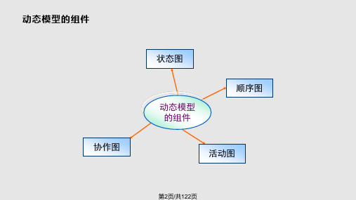
主要内容
• 6.1 状态图的基本组成成分 • 6.2 状态的分类与描述 • 6.3 状态迁移的触发与描述 • 6.4 活动图与状态图的比较 • 6.5 动态状态模型建模案例-信贷管理子系统 • 补充: 使用rose画状态图
第6页/共122页
• 6.1 状态图的基本组成成分 • 6.1.1 对象状态的基本描述图符 • 6.1.2 状态的迁移 • 6.1.3 一个无人职守电梯升降的状态图
第17页/共122页
第18页/共122页
6.1.2 状态的迁移
• 一个对象从一个状态改变成另一个状态称为状态迁移 • 状态的迁移用连接这两个状态的实箭线表示。在状态的迁移箭线上写上引起该迁
移的事件、条件和动作。 • 当事件发生时,动作发生,执行从一个状态到另一个状态的迁移,称为迁移点火
或状态触发。
• 6.3 状态迁移的触发与描述 • 6.3.1 状态的迁移触发
第27页/共122页
• 6.1 状态图的基本组成成分 • 6.1.1 对象状态的基本描述图符 • 6.1.2 状态的迁移 • 6.1.3 一个无人职守电梯升降的状态图
• 6.2 状态的分类与描述 • 6.2.1 对象的状态属性 • 6.2.2 简单状态与嵌套状态 • 6.2.3 状态的顺序迁移-顺序状态 • 6.2.4 状态的并发迁移与同步-并发状态与同步 • 6.2.5 嵌套状态中的历史状态指示器
第42页/共122页
子状态的关系
• 与关系说明复合状态中在某一时刻可同时到达多个子状态(称为并发子状态)。 具有并发子状态的状态图称为并发状态图。
前进和低速 前进和高速 后退和低速 后退和高速
第43页/共122页
6-6 描述设备(车床)状况的嵌套状态图
系统工程与需求工程方法详解演示文稿

可以理解、建模和管理的,识别每个系统的输入和输出,以便
能理解、定义和建模它们与其所处环境之间的交互方式;
➢ 因为没有一个系统是完全正确的,能反应一个不断变化世界的发
杂性,所以要准备好试验不同的系统模型直到找到一个最合适的。
第18页,共38页。
➢ 一个系统保留太长时间是有害的。 ➢ 必须领会到系统分析时没有完全正确的答案;
第19页,共38页。
4.1.3 系统分析员
1. 系统分析员职责
❖ 研究使用单位的存在问题和需要,理解组织(使用单位)的目标、 结构和业务过程;
❖ 确定利用信息技术的优势,改进使用单位工作的最佳方法;
❖ 帮助系统用户和管理者定义新的或增强的系统的需求
公告、公司新闻等。
第36页,共38页。
•收集和研究业务文档的优缺点
❖ 优点
第11页,共38页。
➢ 稳定的不稳定的系统。一个稳定的系统表现为动态平衡,或通过状态 改变对内部和外部事件做出反应,但改变是非常微小的或返回到一个接 近于以前的状态;一个不稳定的系统对内部和外部的反应是不确定的、 不可预期的或大多时候 比例失调。
➢ 自适应和非自适应的系统(或活动的和非活动的系统)。一个 自适应或活动的系统是一个能回应环境变化和外部干预事件的 系统;一个非自适应或非活动的系统是对环境变化和外部干预 事件不能做出回应的系统。
第29页,共38页。
访谈过程中:
❖ 要注意观察身体语言和感情流露,帮助准确理解;
❖ 要坦诚,并创造和谐的环境; ❖ 要告诉被访问者调查内容的用途;
❖ 以自己的理解复述被访性问题,时刻领会调查不是评价或批评;
❖ 要使用清晰和准确的语言,不要使用过于专业术语; ❖ 避免冗长和复杂的问题,及时中止不必要的访谈; ❖ 不要用“你们”对一组人提问等; ❖ 大部分时间是倾听和记录。
经典分子动力学方法详解课件
第19页,共39页。
基本单元大小的选择
• 基本单元的大小必须大于2Rcut(Rcut是相互作用势的 截断距离)或Rcut<1/2 基本单元的大小。这保证了任
何原子只与原子的一个镜像有相互作用,不与自己的镜 像作用。这个条件称为“minimum image criterion” • 在我们所研究的体系内的任何结构特性的特征尺寸或任 何重要的效应的特征长度必须小于基本单元的大小。 • 为了检验不同基本单元大小是否会引入“人为效应”,必 须用不同的基本单元尺寸做计算,若结果能收敛,则尺寸 选择是合适的。
MD方法的发展史
• MD方法是20世纪50年代后期由B.J Alder和T.E. Wainwright创造发展的。他们在1957年利用MD方法, 发现了早在1939年根据统计力学预言的“刚性球组成 的集合系统会发生由其液相到结晶相的相转变”。
• 20世纪70年代,产生了刚性体系的动力学方法被应 用于水和氮等分子性溶液体系的处理,取得了成功。 1972年,A.W. Less和S.F. Edwards等人发展了该 方法,并扩展到了存在速度梯度(即处于非平衡状态) 的系统。
建立完全弹性碰撞方程,借以求解出原子、分子的运动
规律。这种处理可以在液晶的模拟中使用。 • 质点力学模型是将原子、分子作为质点处理,粒子间
的相互作用力采用坐标的连续函数。这种力学体系的应 用对象非常多,可以用于处理陶瓷、金属、半导体等无
机化合物材料以及有机高分子、生物大分子等几乎所有
的材料。
第14页,共39页。
• 为了减小“尺寸效应”而又不至于使计算工作量过大,对
于平衡态MD模拟采用 “周期性边界条件”。
第16页,共39页。
动态系统模拟的方法

通过假设进一步明确理发店系统的运行,为 模拟工作做好准备。 对理发店系统进行了部分简化,是一种理想 化的模拟。基于解决实际问题的目标,在模拟 模型中可以考虑更复杂的情形。 根据假设模拟变量处理如下 1)取时间步长Δt=1(分钟),在任一分钟内有 一名顾客到达的概率是0.5; 2)每位顾客服务时间取为两类顾客的平均服务 时间:5×0.6+8×0.4= 6.2(分)。 时间步长法自然易理解, 模拟过程 但需加快模拟速度。
(2)面向事件法(可变时间增量法) 采用不等时间间隔步长的,仅在人们关心的 事件发生的时间点上考察系统的状态变化,从 而加快模拟的求解过程。 基本思想:对对象系统的一系列不同性质的 事件,按照发生时间的先后顺序逐个进行考察。 时间是可变的 t 0 模拟方法:编制计算机程序时设置一面“模拟 钟”,当有一个事件发生时,才向前走一步, 模拟钟走过一步后,自动地寻找下一个最先使 系统状态发生变化的事件。
停止模拟过程 事先规定运行时间; 的两种方式: 设置为某个特定事件发生; 两种模拟方法的比较: 1.如果一个系统的事件出现无明显的规律,常 采用面向事件法,可以节约计算机运算时间。 2.如果对象系统中事件发生得非常频繁,而且 具有一定的规律,为获取较多的信息,可采用 时间步长法。
3.系统运行机制的描述 模拟思路必须清晰,对模拟的系统对象的运行 机制、模拟变量做到心中有数。
分析与问题思考:
1.模拟模型中用指数分布随机变量模拟顾客 的到达间隔时间,能否用其他随机分布? 2.为顾客的服务时间由理发方式确定为两个常 数,若服务时间是随机变量如何模拟?
系统模拟是研究系统,特别是动态系统的 重要方法,对于: 1). 结构复杂的系统; 2). 很难用解析方法求出变量关系的系统; 3). 内部机理不明的“黑箱”系统; 4). 为验证用其他方法建立的模型及结果。 应是较好的选择。 一. 排队系统简介
Simulink仿真教程(共77张)
仿真技术
第8页,共77页。
第九章 Simulink动态仿真
指令窗
该窗是进行各种 MATLAB 操作的最主要窗口。在该窗内,可键入各种送给(sònɡ ɡěi)MATLAB 运作的指令、函数、表达式;显示除图形外的所有运算结果;运行错误时,给出相关的出错提示。
仿真技术
第9页,共77页。
第九章 Simulink动态仿真
仿真技术
第6页,共77页。
第九章 Simulink动态仿真
5、 Simulink与建模仿真 (1) Simulink
Simulink是一种用来实现计算机仿真的软件工具。它是MATLAB 的 一个(yī ɡè)附加组件,可用于实现各种动态系统(包括连续系统、 离散系统和混合系统)的建模、分析和仿真。
第九章 Simulink动态仿真
Simulink动态(dòngtài)仿真
1 Simulink 基本操作 利用Simulink进行系统仿真的步骤是: ① 启动Simulink,打开Simulink模块库 ② 打开空白模型窗口; ③ 建立Smulink仿真模型; ④ 设置仿真参数,进行仿真; ⑤ 输出仿真结果。
仿真技术
第5页,共77页。
4、 仿真的三要素
第九章 Simulink动态仿真
计算机仿真的三个基本要素是系统、模型和计算机,联系着它 们的三项基本活动是模型建立、仿真模型建立(又称二次建模 )和仿真试验。
数学仿真采用数学模型,用数学语言(yǔyán)对系统的特性进行描述, 其工作过程是:
1、建立系统的数学模型; 2、建立系统仿真模型,即设计算法,并转化为计算机程序,使 系统的数学模型能为计算机所接受并能在计算机上运行; 3、运行仿真模型,进行仿真试验,再根据仿真试验的结果进一 步修正系统的数学模型和仿真模型。
(13)化学反应器的动态模型共21页文档

v
Z=0
Z
Z+dZ
Z=L
若组分A的摩尔浓度为x,则质量衡算式为:
A d Z x t v A x v A (x Z xd Z ) A ( D A Z x) A D A Z x Z D A Z x d Z k x A d Z x t D A Z 2x 2 v Z x k x
力学方程式。 对于非均相反应或非理想流动,则需列出相间传递
方程和流动模型方程,本质上属于物料衡算范畴。
化学反应器的基本方程
一、反应器质量衡算式 组分i的物料衡算:控Βιβλιοθήκη 体内经对流进经对流离
经有效扩散
1 2 - 3 4 物料随时 = 入控制体
间变化率
物料流率
开控制体 + 进入控制体
物料流率
的物料速率
质量衡算式:1=6,即:
V dci dt
Vi R
反应器质量衡算式
2、连续操作理想混合搅拌槽式反应器质量衡算
基本假设:全混流动。
质量衡算式:1=2-3+6
Vdc0 dt
Fici F0c0ViR
3、理想活塞流管式反应器质量衡算
基本假设:活塞流。
质量衡算式:1=2-3+4-5+6
反应器质量衡算式
②连续操作理想混合搅拌槽式反应器
③理想活塞流管式反应器
化学反应器的基本方程
化学反应动力学与宏观反应动力学区别:
化学反应动力学(本征动力学)是指在实验室 理想条件下研究化学反应进行的机理及反应物 系组成、T、P等参数,但不包括传递过程和反 应器结构等对反应速率的影响。
在工业规模化学反应器中化学反应与传质、传 热及动量传递过程同时进行,是化学反应过程 与物理传递过程的综合。
水资源规划及利用

三、多目标规划法在水资源优化配置中的应用
• 水资源优化配置方案,是在分析规划流域 (或区域)水资源条件、了解经济发展现状、 预测未来发展趋势的基础上,通过建立水资 源优化配置模型而制定的。
第27页/共49页
三、多目标规划法在水资源优化配置中的应用
• 水资源优化配置具有多种目标和多个约束条件, 因此可以采用多目标规划法来建立 • 2.水资源开发利用现状分析 • 3.水资源供求预测和评价 • 4.水资源承载力研究
第39页/共49页
• 水资源承载力是指在一定区域或流域范围内,在一定的 发展模式和生产条件下,当地水资源在满足既定生态环 境目标的前提下,能够持续供养的具有一定生活质量的 人口数量,或能够支持的社会经济发展规模。
寻找解决问题的具体措施以实现目标的关键环节,具体 包括方案制定、方案综合评价和最终方案选择等工作。 1.方案制定 • 规划方案就是在既定条件下能够解决问题、实现规划目 标的一系列措施的组合。在流域水资源规划中常常需要 制定多个可能的规划方案,但规划方案并不是越多越好, 方案数量取决于规划性质、要求和掌握的资料等因素。
第30页/共49页
一、水资源规划工作流程与主要内容 水资源规划的步骤,也因研究区域的不同、水资 源功能侧重点的不同、所属行业的不同以及规划 目标的高低不同,有所差异。但基本程序类似, 概括如下:
第31页/共49页
第32页/共49页
二、规划成果要求
• 水资源规划是一项复杂的工作,涉及面比较广。特别是, 面向可持续发展的水资源规划要密切联系社会经济发展、 生态环境问题等内容,需要把它们结合在一起来研究。
• 水资源承载力的主体是水资源,客体是人口数量和社会 经济发展规模,同时维持生态系统良性循环是基本前提。
非线性动态系统模型与辨识.pptx
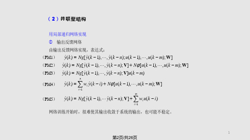
网络模型:
xo (k 1) H Wyc (k 1)1Wu(k )1 yc (k ) o(k 1) f (xo (k 1)) y(k )2 Wo(k )
yc (k )
u(k)
o(k 1)
yˆ(k 1)
实时调整权值动态 BP 算法:
2wi (k ) (k )oi (k ) e(k )oi (k )
0.022
R(k ) R(k ) R(k 1)
-0.046
0.0215
0.021
-0.048
0.0205
7.5
8
7.5
8
图 3-5-4 测试数据分析
(a) z x (k) R(k) (b) z y (k) R(k)
5
第6页/共26页
选择并联结构非线性 DTNN 为辨识模型:按拍延迟线+BP 网络
①一轴辨识模型
x 轴(N2,3,1) y 轴(N2,3,1)
x(k 1) Nx[ R(k ), R(k ); W] y(k 1) Ny[ R(k ), R(k ); V]
6
第7页/共26页
② 两轴辨识模型
x(k y ( k
1) 1)
NQR(k), R(k); W2
x y
(k) ( k )
f(x) :对称型 S 函数。
12
第13页/共26页
设 0.6 ,辨识过程见演示。
(1)辨识器输入 u(k):[-0.5 0.5]间随机信号,此时系统是 BIBO 的; (2)仿真对象输出y (k);辨识器 NNI 输出y y1 ;
(3)
E(k)
1 2
e2
(k)
。
13
第14页/共26页
演示
第3章连续动态系统
称数学操作f 为线性的。
第2页
2013年5月9日
管理学院
连续动态系统的数学模型是微分方程,用于描述动态变量 (状态变量的导数)对状态变量的依存关系以及状态变量之间 的相互关系。只讨论状态变量受时间影响的集中参数系统,用 常微分方程描述,可表示成多元一阶联立方程组,其数学模型 为:
X ' AX
( X ' dX
第24页 2013年5月9日
管理学院
3、定态稳定性
定态稳定性指它附近轨道的稳定性,一个定态是否稳定可 以通过它周围的所有轨道的终态走向来判别。以2维系统的不动 点稳定性为例,为简化计,不动点放在原点。
第14页
2013年5月9日
管理学院
2、暂态与定态
虽然状态空间有无穷多个状态,但在系统学意义下,可以 划分为很少的几类,显示不同的性质,代表不同的动力学行为 特征。 因此,在状态空间研究系统归结为划分不同类型的状态, 描述各类状态的特征,确定不同类状态在空间的分布,描述不 同类状态之间的联系,特别是如何从一类状态向另一类状态转 移的规律。 暂态:指系统在某个时刻可能达到但不借助外力就不能保 持或不能回归的状态或状态集。
管理学院
很多系统可以近似看成线性系统: (1) 整个系统非线性因素微弱; (2) 整个系统非线性因素强,但系统局部(某些点附近)可 以简化成线性系统。 例:2维线性系统
' x1 a11 x1 a12 x2 ' x2 a21 x1 a22 x2
a11 a12 X X AX a21 a 22
和参量空间中用几何法等定性手段来研究非线性系统,了解其定性
性质。
第12页
2013年5月9日
面向对象的开发方法PPT课件可编辑全文
第二节 面向对象的基本概念
类A
A的实例a1
A的操作
类A
实
A的变量
A的实例变量
现 继
承
机
制
类B:A的子类
B的实例b1
的
原
从A继承特性
类B
理
B的操作 B的变量
继承来的A的 实例变量
B的实例变量
第24页/共73页
第二节 面向对象的基本概念
• 继承具有传递性 • 如果类C继承类B,类B继承类A,则类C继承类A。
第18页/共73页
第二节 面向对象的基本概念
• 操作一般分为三个类型 1. 以某种方式处理数据的操作:如添加、删除、修改、选取等。 2. 执行一次计算的操作 3. 监控一个对象的操作
第19页/共73页
第二节 面向对象的基本概念
六、消息
• 消息是用来请求对象执行某一处理或回答某一要求的信息,是对象之 间建立的一种通信机制,它统一了数据流和控制流。
第28页/共73页
第二节 面向对象的基本概念
十、封装 • 封装是指将方法与数据同放于一对象中以使对数据的存取只通过该对象本身的方法。面向对象程序的 其它部分(对象以外的部分)都不能直接作用于一对象的数据,对象间的通信只能通过明确的消息来 进行。
第29页/共73页
第二节 面向对象的基本概念
面向对象
第2页/共73页
第一节 面向对象概述
• 自90年代以来,软件与硬件之间的差距至少有两代处理器之多,并且这种差距还在增大。当软件系统 变得更加复杂时,常规软件工具、技术和概念已不足以应付,从而使软件开发者陷入了困境。但面向 对象的方法能够控制软件的复杂性,从而促进了面向对象的发展,掀起了一股“面向对象”热。
定量分析方法讲课文档

第十页,共21页。
二、霍尔和切克兰德的系统方法论
霍尔的“三维结构”模式
公共管理的霍尔管理矩阵
逻辑维(步骤)
明选系系方
付
确择统统案
诸
问目综分优
实
时间维(阶段)
题标合析化
施
7 6作出决策 5 4 3 2 1
1.规划阶段 2.方案阶段 3.研制阶段 4.生产阶段 5.运行阶段 6.更新阶段
定量分析方法
第一页,共21页。
第2章 系统方法论
主要内容 一、系统思想的产生
二、霍尔和切克兰德的系统方法论
三、综合集成方法学 四、物理-事理-人理(WSR)系统方法论 五、“5W1H”方法
第二页,共21页。
第2章 系统方法论
重点问题 ●还原论与整体论
●霍尔的三维结构模式
●切克兰德的“调查学习”模式
●WSR系统方法论 ●解决问题的“5W1H” ●从定性到定量的综合集成方法
第三页,共21页。
一、系统思想的产生
系统思想
• 古代朴素的系统思想——“不见树木,只见森林” • 近代的形而上学思维方式和格物致知的分析——“只见树
木,不见森林” • 现代的系统思想——“既见树木,又见森林”
第四页,共21页。
✓ 只要是工程实践,不论其具体内容有多么不同,分析 和解决问题的思考程序大体是一致的。
✓ 思维过程的这种逻辑同型性是工程过程的客观逻辑型 的主观反映,哲学上称思维与存在的一性。
第七页,共21页。
二、霍尔和切克兰德的系统方法论
霍尔的“三维结构”模式
•以三峡大坝的修建为例 ➢ 要不要修? ➢ 修在哪里?修成什么样?会有什么影响?怎么解 决? ➢ 怎么修?设计、施工、移民…… ➢修
软件工程中的软件系统分析与建模

《软件设计模式》
系统总结常见的软件设计 模式,有助于提高软件质
量和可维护性
UML示例图
第24页 附录
测试报告范例
设计模式应用案例
展示UML建模在软件系统 分析与建模中的具体应用
场景
示范测试报告的撰写和分 析,提高软件测试的效率
和成果
实际案例展示设计模式在 软件开发中的应用,帮助
理解并应用于实践
设计和部署应用程序以最大限 度地利用云计算的优势
模块化
将系统拆分为独立模块
软件设计原则
高内聚低耦合
模块功能相关性紧密、耦合度低
可维护性
便于系统维护和更新
软件设计方法
软件设计方法是指在进行软件设计时应该采用的方 法。结构化设计是一种将系统划分为各个部分进行 设计的方法,面向对象设计则是以对象为中心进行 设计。数据驱动设计和事件驱动设计都是根据数据 或事件来进行软件设计的方法。不同的设计方法适 用于不同的场景,选择合适的方法对于软件设计至 关重要。
软件设计方法
软件设计方法是指在进行软件设计时采用的 一些具体方法论,包括结构化设计、面向对 象设计、数据驱动设计和事件驱动设计。结 构化设计是一种按照结构化原理进行软件设 计的方法,面向对象设计则是以对象作为设 计和实现的核心,数据驱动设计和事件驱动 设计则是在设计过程中以数据或事件驱动系
统行为和逻辑。
实体-关系图,描述数据实 体及其关系
需求变更管理
需求管理
需求跟踪管理
需求优先级管理
管理需求变更,确保系统 稳定性
追踪需求实现情况,保证 需求准确性
确定需求的优先级,合理 安排开发顺序
结语
软件需求分析是软件工程中至关重要的一部分,通 过分析用户需求、设计系统结构,能够为软件开发 过程奠定坚实的基础。合理的需求管理可以有效避 免项目中的需求风险,提高软件质量和用户满意度。
生理系统建模与仿真讲课文档

下人体器官的耐受性实验;
14
第14页,共65页。
▪ (3)可作为一种预研的手段,为真实系 统运行奠定基础
➢ 例如:可通过进行大量的仿真实验找出系统的变 化规律,然后再进行少量活体实验进行验证,这 样既可节约大量实验经费,缩短实验周期,又可 减少危险性和提高效率。
27
第27页,共65页。
▪ 鉴于这一基本事实,把通过模型的方法对 事物的表述称为模型空间。
▪ 同时,由于模型是基于某一真实系统而构 造的,因此,在模型空间所得出的问题的 解就与真实空间同一问题的解有必然的联 系。
28
第28页,共65页。
真实系统
模型空间
真实系统的解
模型空间的解
29
第29页,共65页。
缺点:
▪ 仅强调外部观测和系统在某一方面的 整体功能
▪ 无法描述系统的内部结构、局部细节 以及作用机理
58
第58页,共65页。
2.推导方法 ▪ 推导方法适用于那些内部结构和机理已
部分地被人们所认识的系统(灰箱)。 ▪ 我们可以根据这类系统的物理化学过程
以及解剖学与生物学知识,分析推导出 描述系统功能和特性的模型。
31
第31页,共65页。
心 脏 模 型
32
第32页,共65页。
血管铸型
33
第33页,共65页。
用乒乓球做肾脏血管铸型标本
1. 先将猪肾洗净,用生理食盐水冲洗动脉,移除血块
2. 准备胶液:将乒乓球剪碎加入丙酮,乒乓球对丙酮的比例 约为1:10。数分钟后乒乓球会溶解形成炼乳状沉在底部。 将炼乳状的胶液倒入针筒内。
25
第25页,共65页。
一个模型的建立需要: ▪ 实际条件理想化; ▪ 具体事物抽象化; ▪ 复杂系统简单化
MIKE 21 3 FLOW MODEL FM
MIKE 21/3 FLOW MODEL FM沙模块用户使用手册目录(Contents)目录(Contents) (1)1 关于本文档(About this guide) (3)1.1 编写本文档的目的(Purpose) (3)1.2 用户所需的知识背景(Assumed User Background) (3)1.3 MIKE Zero 模型编辑器程序界面结构(General Editor Layout) (3)1.3.1 导航栏(Navigation tree) (3)1.3.2 编辑窗体(Editor window) (3)1.3.3 有效性显示窗体(Validation window) (4)1.4 在线帮助系统(Online Help) (4)2 引言(Introduction) (5)2.1 概述(General specification) (5)2.1.1 适用范围(Application areas) (5)3 说明(Getting started) (6)4 示例(Examples) (7)4.1 概述(General) (7)4.2 U 型河道示例(U-shaped flume) (7)4.3 环流示例(Sand transport in circulation current) (7)5 沙模块(Sand Transport Model) (7)5.1 模型定义(Model Definition) (7)5.1.1 概述(General description) (8)5.1.2 床面活动层厚度(Layer thickness) (8)5.1.3 驱动力参数(Forcing parameters) (8)5.1.4 单一水流工况(Pure flow) (8)5.1.5 波流共同作用工况(Combined current and waves) (9)5.2 时间参数(Time Parameters) (10)5.3 求解格式(Solution technique) (10)5.3.1 备注与提示(Remarks and hints) (11)5.4 泥沙特性(Sediment properties) (11)5.4.1 泥沙特性(Sediment properties) (11)5.4.2 推荐取值(Recommended values) (12)5.5 床面阻力(Bed resistance) (12)5.5.1 概述(General description) (12)5.5.2 参数取值(Data) (13)5.5.3 推荐取值(Recommended value) (13)5.6 驱动力参数(Forcings) (13)5.6.1 波浪(Waves) (14)5.6.2 水流(Flow) (15)5.7 扩散(Dispersion) (16)5.7.1 平流扩散(Horizontal dispersion) (16)5.7.2 对流扩散(Vertical dispersion) (17)5.7.3 推荐设置(Recommended values) (17)5.8 源汇项(Sources) (17)5.8.1 源汇项设定(Source specification) (18)5.8.2 备注与提示(Remarks and hints) (18)5.9 初始条件(Initial Conditions) (18)5.9.1 泥沙粒径组分浓度(Fraction Concentration) (19)5.9.2 床面活动层厚度(Layer thickness) (19)5.10 边界条件(Boundary Conditions) (20)5.10.1 边界设置(Boundary Specification) (20)5.11 地貌演化模块(Morphology modoule) (21)5.12 输出(Outputs) (21)5.12.1 图形化查看(Geographic view) (21)5.12.2 输出类型(Output type) (22)5.12.3 输出项(Output items) (26)6 地貌演化模块(Morphology module) (29)6.1 概述(General description) (29)6.2 模型定义(Model definition) (29)6.3 时间参数(Time Parameter) (30)6.4 河岸侵蚀(Bank Erosion) (30)6.5 边界条件(Boundary conditions) (30)6.5.1 边界说明(Boundary specification) (30)1 关于本文档(About this guide)1.1 编写本文档的目的(Purpose)编写本文档的主要目的在于指导用户使用MIKE 3 Flow Model FM 模型中的沙模块(非粘性泥沙输移的计算)。
霍尼韦尔UniSim Design动态模拟在先进控制APC中的应用

Advanced Process Control in the Plant Engineering and Construction PhaseVassilis Sakizlis∗, Andy Coward♠, Kumar Vakamudi♣, Ivan Mermans♠.1. IntroductionThe profit in process industries is a function of effective plant operation. This energy and economic based incentive leads to the development of advanced operation and control strategies (See Qin and Badgwell, 2003; Christofides et al., 2008).The success of advanced control in the oil and gas industry, in particular, over the last 30 years is widely acknowledged. Successful applications have been reported in olefin plants (Shindo et al., 2004), refineries (Moro and Odloak, 1995; Haseloff et al., 2007) and gas plants (Hotblack, 2004; Honeywell 2005). Payback times of a few months have been achieved, in addition to improved economics by 5-10%. The success of these projects is attributed to increased profit margin and reduction in the energy consumption. Currently, the main research and development trends in that field focus on centralized co-ordinated control for plant – wide solutions (Cheng et al.,2007), non-linear models (Kumar and Daoutidis, 2002) and multivariable optimizing solutions that can be incorporated in a PLC or DCS hardware (Dua et al., 2008).Predominately, however, advanced control is developed, installed and commissioned after the plant start-up. Dynamic simulation may be used to expedite the step testing and plant model development, however, the set-up of the system is still held until at least after the plant commissioning. This conventional strategy (Figure 1) inadvertently introduces a delay in the advanced control implementation and consequently postpones the capitalization of the relevant benefits.∗ Bechtel Ltd. 245 Hammersmith Road, W6 8DP, London, UK.♠ Honeywell Process Solutions, Lovelace Road, Bracknell, Berkshire, RG12 8WD.♣ Bechtel Ltd, 3000 Post Oak Boulevard, 77056, Houston, Texas, USA.Figure 1. Conventional Approach to Multivariable ControlIn the novel work presented here we have minimized this delay by providing advanced process control at the early stages of the process design and engineering. The work concerns the design, testing and installation of advanced control (also termed as multivariable control – MVC) as part of the engineering and construction of an approximately 1300 MMSCFD gas plant in the Middle East.The MVC scope of work as part of the EPC (Engineering Procurement and Construction) phase included:Multivariable Predictive Control hardware and software supply, installation and integration.Development of a dynamic simulation model for testing the MVC performance.Supply and configuration of the DCS-OPC interface communication.This interface comprises software, hardware and the necessary graphicsand logics.The contractor (Eastern Bechtel) managed, supervised and provided information to the vendor (Honeywell) who developed and delivered the MVC.The next section explains the prime terms used in this article. The following paragraphdescribes briefly the process while focusing on the NGL recovery system. Thefollowing sections describe the steps that were followed starting from the dynamic model development for the NGL recovery system and finishing with the MVC training for operators and engineers.2. Definitions−Dynamic simulation model: Non-linear model of the process plant based on first principles and built on a commercial software, e.g.HYSYS, UniSim, gPROMS.−Linear dynamic model. Model derived from plant excitation data. The form of this model can be finite time impulse responses, transferfunctions, state space or AutoRegressive eXogeneous model (ARX).This model is in general used to derive a multivariable control solutionfor the plant.−Multivariable Control (MVC) refers to control algorithms that simultaneously compute the optimal value of a set of manipulatedvariables based on a selected set of current plant measurements. Thecomputation is the on-line solution of an optimization problemconsisting of :an economic or tracking objective functionthe linear dynamic model of the system andperformance and operational constraintsFor more information on MVC that is also called APC (AdvancedProcess Control) or MPC (Model Predictive Control) refer to Quin andBadgwell (2003). The Honeywell proprietary MVC controller is theProfit Controller algorithm and software.3. Process DescriptionThis gas plant facility includes process units for gas and condensate separation, condensate stabilization, gas treating, gas dehydration, NGL recovery and residue gas injection. The simplified plant flowsheet is shown in Figure 2. The main products from the plant are outlined on Table 1.Table 1. Products of the gas plant.No Product Plant Unit1 Condensates C5+ Condensate Stabilizer bottomsand Liquid Separation bottoms2 Natural Gas Liquids(NGL), mostly C3, C2 NGL recovery unit and Liquid Separation bottoms3 Sweet natural gas C1,C2NGL recovery overheadFigure 2. Gas Plant flowsheet.The scope of MVC concerned the three main separation units that are directly linked with the plant production, i.e. the condensate stabilizer and the feed liquid separation unit that remove the heavy components from the gas stream;; and the NGL recovery system that includes a demethanizer distillation column.The unit which attributes most to the plant production and the one which benefits the most from applying the Multivariable Control (MVC) optimization is the NGL recovery system. Figure 3 is a simplified process flow diagram of the NGL recovery system that omits the details that are not relevant to MVC. The NGL Recovery Unit utilizes UOP/Ortloff’s licensed Supplemental Rectification Process (SRP) (US patent number 7,191,617) technology to efficiently recover the ethane from the dehydrated gas while maintaining 99+% recovery of the propane and heavier components for the wide range of ethane recoveries. The resulting residue gas is routed to the residue gas manifold for reinjection after being re-compressed by two compressors in series that control the pressure in the unit.The NGL recovery process includes a multi-stage propane refrigeration circuit toprovide the additional cooling duty required to meet the product specifications.Figure 3. NGL recovery flowsheet and representation of MVC manipulated variables.4. MVC Objectives and Control SchemeHere, we describe the formulation of the control structure for the NGL unit. The same approach was used in the rest of the relevant units.The prime MVC objectives were to•Minimise the C3+ composition in the overhead product and maximize C3recovery in the bottoms product.•Minimise the C2+ concentration in the i.e. in the NGL stream during C2recovery and the reverse during C2 rejection.•Maximise plant production rate.•Minimise plant energy usage.At the same time operational constraints should not be exceeded. For example, the C1/C2 ratio in the bottoms product should be maintained below a designated set-point, while the pressure in the overhead gas stream should not deviate from its given value. To satisfy the aforementioned constraints and objectives the contractor (Bechtel) compiled the set of manipulated and control variables that constitute the MVCstructure. The main selection criteria were:−The manipulated variables (MVs) should have a large impact on the process objectives and constraints. Additionally, the effect of the MVson the process objectives should ideally be immediate without largedelays. For example, reducing the temperature of the feed to thedemethanizer at constant pressure, leads to a reduction in the columntemperature, hence increasing the liquid ethane recovery.−The control variables had to be directly linked to the objectives and constraints of the process. For example the pressure at the columnoverhead is a constraint and therefore, was included in the structure.−The number MVs and CVs should be kept at a relatively low level to avoid complexities during tuning and commissioning and to preventnegative effects on the NGL or other parts of the plant. For example thepressure at the NGL inlet was not used in the structure as it may affectadversely the downstream units.The awareness here of the contractor on the plant operation and design was paramount to the determination of the control structure.5. Configuration and Testing of MVC ControllerBecause the “real” process for this project did not exist at the time of the MVC project, the testing of the developed MVC applications could be handled in one of two ways;•Testing against a “perfect” inverted linear dynamic model with the Profit Design Studio,•Testing of the Profit Controller against the control loops and the process model within a dynamic simulation model.To demonstrate how the Profit Controller would act with unmeasured and process disturbances, the latter option was chosen.5.1. Dynamic ModelA dynamic model of the plant was under construction by the contractor (Bechtel) to conduct design studies and to serve as a platform for the operator training plant simulator (OTS). The development of the model was a joint effort by the Bechtel Advanced Simulation Group and the Bechtel Process discipline of the gas plant project. This model is a detailed representation of the plant steady state and dynamic behaviour. For instance, it accounted for hydraulics, compressor performance curves and the modelling of the dominant stream components. The NGL portion was extracted from the plant model and after a set of modifications it was handed over to the vendor (Honeywell). The main modifications were:1.The boundaries of the unit were modelled as points of constant pressure. Theseare the feed to the unit, the residue gas to the re-injection compressors and theNGL product.2.The two ratio controllers were configured. These were the ratio of the side streamover the feed flow and the ratio of the by-pass to the turbo-expander over the feed flow.3.The settings of level controllers and the column bottoms temperature controllerwere revisited.The original model and the majority of the modifications were developed in HYSYS 2004 by Bechtel. Honeywell read, simulated and edited the model as necessary using UniSim. The compatibility between the two pieces of software obviated rebuilding the entire or parts of the model.5.2. Step Testing for MVC - Profit ControllerAny linear multivariable controller requires dynamic response models of the process it is controlling. These responses are normally obtained by perturbing manipulated variables, i.e. introducing step changes in the setpoint of the control loop (hence step testing.) This activity requires that the process move close to limits and quality constraints and also requires that all other process disturbances are minimised. This limits the operator in his normal role and introduces the risk of going off specification or facing an abnormal situation.By developing a matrix of dynamic responses from the UniSim dynamic simulation, the response models are obtained in a risk-free environment. The time to develop the models is also reduced.The step testing activities alone on a demethaniser would normally take at least a week, even using efficiency tools such as Profit Stepper (closed loop step testing with online model identification) because of the time to the fractionation column takes to reach a steady state after a process move. Utilising UniSim meant that a sequence of step tests could be configured once and then left to run, with the UniSim simulation set to run as fast as possible. This meant that the dynamic model starting from a steady state could be saved and run as required, depending upon the results obtained. Because the process is a simulation, variables that cannot normally be fixed (such as ambient temperature) could also be held constant to improve the overall model quality.If base control loops needed retuning, they could be adjusted and then the step testing sequence run again overnight to provide data for analysis in the morning. On the live process, this activity would require re-testing the process, with delays for the project, additional cost and potentially additional risk for the customer.Results obtained from the UniSim model were extremely encouraging and compared favourably in terms of gains and dynamics to models obtained from a similar unit in another Honeywell project, which had been step-tested using conventional methods. This demethaniser, located in the Middle East, used the same licensor design and provided a good reference for model gains and dynamics. Examples of the responses obtained from UniSim are shown below.Figure 4. Response of C2/C2 ratio to Demethaniser Feed temperature.Figure 4 indicates that if the feed temperature to the demethaniser is increased (gets less cold) then the ratio of methane to ethane in the demethaniser bottoms would increase. This agrees with expectations – less “cold” entering the system with constant reboil would recover less ethane. Similarly, increasing the reboil would decrease the ratio because more methane would be driven up the column. As can be seen, the responses are very clean, with no disturbances and very self-similar models for different settling times. The main benefits from the testing activities via a dynamic simulation model are:a.The linear model derived from the UniSim dynamic simulation can potentially beused for commissioning of the real plant MVC.b.The generation of the dynamic model and subsequently the realistic linear modelenabled the testing of the MVC graphics, databases.c.The models provided insight into the correlations between the manipulated andcontrolled variables that can be essential during commissioning and tuning of the real plant MVC.5.3. Profit Controller Configuration and performance evaluationOnce the linear dynamic model was derived the configuration of the MVC controller was completed in the Profit Design Studio where the objective function weights and constraints are set. This activity allowed the installation of the MVC controller on the real MVC hardware and the generation of the MVC graphics, the MVC database and the MVC-DCS interface.The MVC controller was integrated with the UniSim dynamic model to evaluate the controller performance. UniSim contains an option where MVC can be added to the process - Profit Controller (Figure 5) is one of those options and can be added and then connected to relevant points across the process. In this case, the Profit Controller application was configured to link to the setpoint of all the base control loopsFigure 5. Profit Controller Integrated in UniSim.Controlled variables are also connected to the Profit Controller from different points in the process. Where specific instruments were going to be connected to the Profit Controller, the stream properties (temperature, pressure or flow) at the location closest to where the instrument would be situation were used, converted to the appropriate units to be used at site. Where a property or composition was used, the particular component or stream composition was used as the source value.Utilising the UniSim dynamic model meant that where qualities or compositions were required, preliminary inferential models could also be identified. For example, the online application would require the methane and ethane concentrations in the demethaniser bottoms stream to be inferred by online calculations. Using information from the dynamic simulation, preliminary inferential models were developed and then tested over the expected operational range. The actual inferential models will be validated against the laboratory results once the process is commissioned. Subsequently, the inferential model will be adjusted accordingly if necessary.5.4. MVC Simulated Cost BenefitsDuring the ethane recovery mode, the objective of the MVC application on the demethaniser column was to maximize the recovery of ethane and heavier components from the methane stream and therefore the methodology used was to compare the ethane recovery data both before and after MVC implementation.The UniSim simulations were started and allowed to stabilise; the data for key parameters collected then forming the base case for the pre-MVC scenario. The Profit Controller wasthen switched ON and data collected with Profit Controller controlling the process – thisdata then formed the post MVC case. The comparison of these two cases data provided the expected benefits of MVC on demethaniser column.During a conventional project, this methodology would be very conservative, since improvements in base level control loop design and tuning would also contribute to the overall project benefits. However, in this case, the approach served to highlight the benefits.Following (Figure 6) are trends developed from UniSim Design showing the process data as the MVC was commissioned on the virtual dynamic model based plant.Figure 6. Trends of the C1/C2 ratio and C2 recovery with and without MVCFrom the data extracted from UniSim, the benefits of Profit Controller on the demethaniser are expected to be approximately 1.37% increase in the ethane recovery. This could translate to $5-6m per year savings based on the current NGL and natural gas price.Additional benefits are anticipated if the Profit Controller is allowed to change the NGL unit upstream pressure that consequently controls the feed flow to the unit. However, this variable is currently excluded as it may cause instabilities in upstream units. During the actual commissioning activities the decision to utilise this variable will be re-examined to potentially increase the MVC benefits.6. DCS – MVC InterfaceThe plant DCS was the CS3000 system supplied, configured and implemented by Yokogawa East Asia.The MVC implementation was designed as follows:o The MVC execution software was installed on the MVC server.o The MVC user interface was installed on the MVC workstation to allow monitoring and tuning capabilities.o The MVC server is connected to the DCS via OPC.Redundant links between the MVC server and the DCS OPC servers were employed to enhance the systems reliability. Figure 4 illustrates the architecture.The expected operation is:−MVC server will receive a set of measurements through the plant DCS.−MVC will perform calculations to compute the optimal control actions.−The computed control action will be fed back to DCS controllers in the form of regulatory controller set-points.−The MVC workstation user interface permits the MVC engineer to change the underlying MVC model or even add – remove controllers on the plant units.The DCS had to be configured accordingly to enable the appropriate communication between the two systems. The DCS modifications and the reasons behind them are listed here:6.1. DCS GraphicsAlthough the full operation of the MVC can be performed from the MVC Viewer Workstation, the DCS Human Machine Interfaces (HMIs) should still allow the operator to adjust on-line a selected set of the MVC settings. For example the operator should be allowed to enable and disable the MVC control or manipulated variables. Hence, the DCS vendor developed graphics as per the contractor (Bechtel) and Honeywell instructions. The graphics were integrated with the Yokogawa DCS with appropriate links to the process graphics, while they bear resemblance to the MVC Viewer graphics(Figure 8). This is a feature that can only be materialized at the early construction phase, where there is sufficient time to review the graphics and ensure consistency and compliance with the project philosophy.6.2. DCS logicThe controllers that were admitting MVC set-points had to be configured accordingly to allow an automated switching from the MVC to the DCS mode of operation. Additionally a portion of logic was implemented to fall – back the relevant DCS controllers to a safe mode of operation for the following cases:−Lack of communication between MVC and DCS−Emergency shut down in the plant−Manual selection to switch MVC off.6.3. DCS watchdogThe watchdog timer monitors the health of the Profit Controller applications and the health of the DCS-MVC communication. When either the MVC – DCS communication fails or one of the Profit Controller applications degrades, the watchdog alerts the operator and ensures a safe and seamless fallback from the MVC to the DCS operating mode. Traditionally, the watchdog logic resides in the DCS and one watchdog is implemented per Profit Controller application. Here, there was a limitation on the DCS loading that restricted the installation of the watchdog on the DCS. Thus, a new approach was developed that transferred a portion of the MVC logic to the MVC server.MVC Server sideThe MVC Server part of the watchdog is implemented as a Profit Toolkit application. This application receives a watchdog reset signal from each Profit Controller application it is monitoring. If it does not receive a reset signal in a configurable period of time from one of the Profit Controller applications, then the pertinent Profit Controller application has been degraded or corrupted. Hence, it sends the corresponding shed signal to the DCS. The reset signal is a value that is incremented every time the Profit Controller engine executes. This value is always incremented, even if the controller is not on-line.DCS Server sideThe DCS part of the application performs 2 tasks :• It monitors the health of the communications link between the MVC server and the DCS. To do so, it receives a watchdog reset signal from the MVC server side of the application. If it has not received the reset signal for a configurable period of time, it switches all the DCS base level controllers that are used by all the Profit Controllerapplications, back to their fallback DCS mode. The reset signal is a value that is incremented every time the Profit Toolkit watchdog application executes.• It monitors the health of the Profit Controller individual applications. When it receives a shed signal from the MVC server side for one application, it switches the DCS base level controllers that are used by that Profit Controller application, back to their fallback mode. This configuration (Figure 9) maintains the DCS watchdog logic to a minimum and hence gives priority to the critical tasks of the DCS. This is desirable from an operational and maintenance point of view. Note that this implementation reduces the DCS watchdog loading by ≈80%.Figure 7. MVC hardware architecture and connections with DCS.DCS user interface for MVCMVC Viewer interfaceFigure 8. MVC graphics on MVC workstationFigure 9 DCS and MVC watchdog implementation.7. MVC Testing - DCS integrationWhen any Advanced Process Control application is implemented onto a Distributed Control System (DCS), the entire system must always be fully tested to ensure that communication paths are correctly configured and that DCS displays are correctly configured. Limits and values that are entered into schematics by the operator reside in the DCS and these values are then read up to the Supervisory Computer. Each schematic entry point is checked to ensure that the value is being stored in the correct location and then read correctly into the correct location within the MVC application.Fallback strategies need testing where situations such as network disruptions, power failures or system failures are simulated. In each case, on a live system, there is a risk ofinterruption to the process because mode changes and alarms are being triggered on the system controlling the process.Utilising the dynamic model to develop the Profit Controller application allowed the testing of the integration to be performed in complete safety in the factory. All schemes, fallback logic, control loop mode shedding and schematics were fully tested using the developed Profit Controller and the system architecture that would be in place on site. All Ethernet switches, cables, computers and implementation specifics were tested to ensure that they performed as expected. This significantly reduces the risk on site, but more importantly will reduce delays to the project once the process equipment is commissioned.8. MVC TrainingTraining of operators is a fundamental part of any MVC project, since without the operator’s understanding and acceptance of the technology, it will not be used. The best MVC application, if not accepted by the operator, will never remain turned on.Utilising MVC technology is normally a change from the operator workflow. Because the brownfield sites have been in operation for some time, operators have been trained on how to run the unit and have developed their own way of “driving” the process. Between different shifts, significantly different process performance can be observed when historical data is reviewed. Trying to change this behaviour is time consuming and sometimes problematic.Training the operators in the MVC technology, and how to use it, from the outset means that the MVC operation becomes an integral part of their workflow. Standardising the operational methodology from commissioning onwards also means that the operators achieve the best possible performance, all the time.Because the Profit Controller applications were configured at an early stage, all the operators were trained on what the technology would look like, what the objectives would be, what the schematics would look like and how they would control the process using MVC technology. Their work flow was then defined including using Profit Controller.9. ConclusionsAdvanced control has realised substantial economical benefits to operating companies. However, its conventional implementation postpones its installation and testing until after plant commissioning. In this work (outlined in Figure 10), the MVC project has started long before the process construction is completed. Hence, the long lead time items have been completed before the process commissioning starts:1.The design and requirements of NGL unit MVC applications are well understoodand so can be accomplished with a high degree of accuracy at an early stage. In that respect, the engineering firm that designs and builds the plant uses its experience with plant design and operation to ascertain the MVC control structure.2.Control loop interactions and strategies are tested and proven ahead of time,reducing the process commissioning time.3.Risky and time consuming activities such as the process step testing of the plantproduction units (NGL unit, etc.), DCS interfacing and DCS testing are all performed in a zero risk factory environment and fully tested before the system is taken to site.4.Operators are trained and expect the MVC applications as a part of theirfundamental workflow, rather than having to adapt to using the technology at a later stage.The MVC design, installation, testing and commissioning at site would normally last six (6) to nine (9) months. This new approach of transferring a portion of these activities to the engineering phase reduces the site engagement too step testing and commissioning of the stabilizer and liquid separation unitso validation of the process response model for the NGL unito tuning and monitoring of the MVC controller performance.Hence the duration of these activities can potentially be reduced to around one (1) month. This approach significantly accelerates the benefit delivery and enables an earlier improvement in process operation. It thereby, leads to an early payback of the MVC project investment.Figure 10. Advanced Control prior commissioning. Note in Red the MVC elements in the Engineering Phase.。
