RSoft_仿真软件中文实例指导书
(最新整理)PROTEUS中文教程+实例
PROTEUS中文教程+实例编辑整理:尊敬的读者朋友们:这里是精品文档编辑中心,本文档内容是由我和我的同事精心编辑整理后发布的,发布之前我们对文中内容进行仔细校对,但是难免会有疏漏的地方,但是任然希望(PROTEUS中文教程+实例)的内容能够给您的工作和学习带来便利。
同时也真诚的希望收到您的建议和反馈,这将是我们进步的源泉,前进的动力。
本文可编辑可修改,如果觉得对您有帮助请收藏以便随时查阅,最后祝您生活愉快业绩进步,以下为PROTEUS中文教程+实例的全部内容。
目录第一章概述 (2)一、进入Proteus ISIS (2)二、工作界面 (3)三、基本操作 (3)图形编辑窗口 (3)预览窗口(The Overview Window) (4)对象选择器窗口 (5)图形编辑的基本操作 (5)参考1 (10)参考2作原理图仿真调试 (12)四、实例一 (16)电路图的绘制 (17)KeilC与Proteus连接调试 (26)五、实例二 (30)使用元件工具箱 (30)使用状态信息条 (30)使用对话框 (30)使用仿真信息窗口 (30)关闭Proteus ISIS (30)四、菜单命令简述 (31)主窗口菜单 (31)表格输出窗口(Table)菜单 (33)方格输出窗口(Grid)菜单 (33)Smith圆图输出窗口(Smith)菜单 (33)直方图输出窗口(Histogram)菜单 (33)第二章基于51的PID炉温度调节器的硬件设计及仿真(未完成) (34)第一章概述Proteus ISIS是英国Labcenter公司开发的电路分析与实物仿真软件。
它运行于Windows 操作系统上,可以仿真、分析(SPICE)各种模拟器件和集成电路,该软件的特点是:①实现了单片机仿真和SPICE电路仿真相结合。
具有模拟电路仿真、数字电路仿真、单片机及其外围电路组成的系统的仿真、RS232动态仿真、I2C调试器、SPI调试器、键盘和LCD系统仿真的功能;有各种虚拟仪器,如示波器、逻辑分析仪、信号发生器等.②支持主流单片机系统的仿真。
Rsoft软件(BPM,光束传播法模拟)中文课件(5.6光纤模式转换器)江苏大学陈明阳教授编写 2018最新版
总结
1.高阶模的监视器设置 2.重叠区波导折射率确定(通过优先级来改变
重叠区折射率值,谁高[优先级]取谁[折射率差] )
江苏大学陈明阳
2. M.-Y. Chen, G.-D. Cao, Y.-Q. Tong, and L. Wang, "High-order mode conversion based on adiabatical mode evolution for mode division multiplexing applications," Applied Optics 56, 5125-5130 (2017).
倒树结构模场转换效果图
江苏大学陈明阳
模分复用器/解复用器
辅助纤芯6
选取辅助纤芯6的折射率差为0.0063 ,为了实现从单芯端面输入LP21b时 ,能从辅助纤芯6输出
辅助纤芯5
辅助纤芯5选取折射率差为 0.0083,为了实现从单芯端 面输入LP11b时,能从辅助纤
芯5输出辅。 助纤芯1-4
第一类辅助纤芯选取折射率差为 0.0095,该结构能够实现从LP01、 LP11a、 LP21a、 LP02模式的依次输出 。
模式复用器成为模 分复用系统通信性 能优劣的关键性因 素。江苏 Nhomakorabea学陈明阳
光纤模式转换器设计
建模
35um
L=80mm 20um
Rsoft软件示例
模型结构图
江苏大学陈明阳
1 模式转换器的功能设想
能够实现模式从低阶到高阶的转换 以及模式从高阶到低阶的转换
LP21b
LP11a
RSoft_仿真软件中文实例指导书

RSoft 仿真软件指导书RSoft是一款非常实用的光波导仿真软件。
其中包含了BPM,FDTD,FEM等多种算法,使得它能够适用于各种不同要求场合。
本课程主要使用RSoft算法集中的BPM算法对光波导和简单光波导器件进行仿真计算,从而对光在波导中的传输有一定得了解。
一、软件CAD界面:下载网站上的压缩包,解压缩后运行C:\Program Files\RSoft\bin文件夹中的bcadw32.exe,即出现如下图所示的CAD界面。
此界面是定义波导结构和下一步计算的前提。
二、单根波导的仿真:在软件中,点击左上角的”New Circuit”按钮,如图所示。
点击后弹出基本设置对话框,波导的一些基本特性参数需要在此设定。
我们模拟目前光通信系统中应用最为广泛的掩埋型二氧化硅波导(channel型)。
波导横截面的尺寸结构为6um*6um,芯层折射率为1.465,包层折射率为1.455(包层和芯层的折射率差为0.01),通信波长为1.55um。
基本参数的设定如下图所示(注意,软件中关于长度的单位均为um):设置完毕后点击”OK”,进入CAD界面。
首先画一根直波导。
点击”Segment mode”(新建文件时默认就是此模式),如上图红圈所示。
之后在空白的CAD窗口中某一处单击鼠标左键,在任意另一处再单击左键,即可画出一条波导,如下图所示。
到目前为止,画出的波导是任意的,我们还需要对它进行设置,满足我们设计的要求。
将鼠标移动至波导上(红色区域上),再单击鼠标右键,会弹出波导的设置菜单。
由于我们只需要仿真普通的直波导,所以大部分设置保持默认即可。
主要需要调整波导的位置。
在RSoft 软件中,波导位置是由首尾两个坐标确定的,并且BPM计算的光是只沿着z轴传播(即竖直方向),这个是需要特别注意的。
具体设置见下图。
设置完毕单击”OK”,就可以在CAD界面看到修改后的,沿着z轴、长度为1000um的波导(俯视图)。
单单如此还不够,我们还需要设置光源的特性和观察的路径。
Rsoft软件简介和使用教程
RSOFT使用教程目录Rsoft简介 (3)Chapter 7 Tutorials 第七章教程 (5)Tutorial 1: Ring Resonator 教程1:环形共振器 (5)Device Layout: 器件结构: (5)Defining Variables 定义变量 (6)Drawing the Structure 画器件结构图 (6)Checking the Index Profile 核对折射率分布 (9)Adding Time Monitors 添加时间监视(探测)器 (10)Simulation: Pulsed Excitation 模拟:脉冲激发 (12)Launch Field 激发场 (12)Wavelength/Frequency Spectrum 波长/频率光谱 (12)Increasing the Resolution of the FFT 提高FFT的分辨率 (14)Simulation: CW Excitation 模拟:连续激发 (16)Tutorial 2: PBG Crystal: Square Lattice 教程 2:PBG 晶体:四方晶格 (17)Lattice layout 晶格布局 (17)Base Lattice Generation 基准晶格的创建 (17)Lattice Customization 定制晶格 (18)Checking the Index Profile 核对折射率分布 (18)Inserting Time Monitors 插入时间监视器 (19)Launch Set Up 激发场设置 (20)Simulation 模拟 (21)Data Analysis 数据分析 (22)Switching Polarization 改变偏振为TM模 (23)Periodic Boundary Condition Set Up (24)Tutorial 3: PBG Crystal: Tee Structure 教程 3:PBG晶体: T型结构 (24)Tutorial 4: PBG Crystal: Defect Mode 教程四:PBG 晶体:缺陷模型 (24)Rsoft简介包括BeamPROP、FullWAVE、BandSOLVE、GratingMOD、DiffractMOD、FemSIM, 以及MOST软件。
Rsoft软件简介和使用教程讲解

RSOFT使用教程目录Rsoft简介 (3)Chapter 7 Tutorials 第七章教程 (5)Tutorial 1: Ring Resonator 教程1:环形共振器 (5)Device Layout: 器件结构: (5)Defining Variables 定义变量 (6)Drawing the Structure 画器件结构图 (6)Checking the Index Profile 核对折射率分布 (9)Adding Time Monitors 添加时间监视(探测)器 (10)Simulation: Pulsed Excitation 模拟:脉冲激发 (12)Launch Field 激发场 (12)Wavelength/Frequency Spectrum 波长/频率光谱 (12)Increasing the Resolution of the FFT 提高FFT的分辨率 (14)Simulation: CW Excitation 模拟:连续激发 (16)Tutorial 2: PBG Crystal: Square Lattice 教程 2:PBG 晶体:四方晶格 (17)Lattice layout 晶格布局 (17)Base Lattice Generation 基准晶格的创建 (17)Lattice Customization 定制晶格 (18)Checking the Index Profile 核对折射率分布 (18)Inserting Time Monitors 插入时间监视器 (19)Launch Set Up 激发场设置 (20)Simulation 模拟 (21)Data Analysis 数据分析 (22)Switching Polarization 改变偏振为TM模 (23)Periodic Boundary Condition Set Up (24)Tutorial 3: PBG Crystal: Tee Structure 教程 3:PBG晶体: T型结构 (24)Tutorial 4: PBG Crystal: Defect Mode 教程四:PBG 晶体:缺陷模型 (24)Rsoft简介包括BeamPROP、FullWAVE、BandSOLVE、GratingMOD、DiffractMOD、FemSIM, 以及MOST软件。
Rsoft软件简介和使用教程

RSOFT使用教程目录Rsoft简介 (3)Chapter 7 Tutorials 第七章教程 (5)Tutorial 1: Ring Resonator 教程1:环形共振器 (5)Device Layout: 器件结构: (5)Defining Variables 定义变量 (6)Drawing the Structure 画器件结构图 (6)Checking the Index Profile 核对折射率分布 (9)Adding Time Monitors 添加时间监视(探测)器 (10)Simulation: Pulsed Excitation 模拟:脉冲激发 (12)Launch Field 激发场 (12)Wavelength/Frequency Spectrum 波长/频率光谱 (12)Increasing the Resolution of the FFT 提高FFT的分辨率 (14)Simulation: CW Excitation 模拟:连续激发 (16)Tutorial 2: PBG Crystal: Square Lattice 教程 2:PBG 晶体:四方晶格 (17)Lattice layout 晶格布局 (17)Base Lattice Generation 基准晶格的创建 (17)Lattice Customization 定制晶格 (18)Checking the Index Profile 核对折射率分布 (18)Inserting Time Monitors 插入时间监视器 (19)Launch Set Up 激发场设置 (20)Simulation 模拟 (21)Data Analysis 数据分析 (22)Switching Polarization 改变偏振为TM模 (23)Periodic Boundary Condition Set Up (24)Tutorial 3: PBG Crystal: Tee Structure 教程 3:PBG晶体: T型结构 (24)Tutorial 4: PBG Crystal: Defect Mode 教程四:PBG 晶体:缺陷模型 (24)Rsoft简介包括BeamPROP、FullWAVE、BandSOLVE、GratingMOD、DiffractMOD、FemSIM, 以及MOST软件。
RSoft软件许可协议和说明说明书

Obtaining RSoft Software and License Key Files Optical Solutions GroupMarch 2016Copyright Notice and Proprietary InformationCopyright © 2015 Synopsys, Inc. All rights reserved. This software and documentation contain confidential and proprietary information that is the property of Synopsys, Inc. The software and documentation are furnished under a license agreement and may be used or copied only in accordance with the terms of the license agreement. No part of the software and documentation may be reproduced, transmitted, or translated, in any form or by any means, electronic, mechanical, manual, optical, or otherwise, without prior written permission of Synopsys, Inc., or as expressly provided by the license agreement.Right to Copy DocumentationThe license agreement with Synopsys permits licensee to make copies of the documentation for its internal use only. Each copy shall include all copyrights, trademarks, service marks, and proprietary rights notices, if any. Licensee must assign sequential numbers to all copies. These copies shall contain the following legend on the cover page:“This document is duplicated with the permission of Syn opsys, Inc., for the exclusive use of______________________________ and its employees. This is copy number __________.”Destination Control StatementAll technical data contained in this publication is subject to the export control laws of the United States of America. Disclosure to nationals of other countries contrary to United States law is prohibited. It is the reader’s responsibility to determine the applicable re gulations and to comply with them.DisclaimerSYNOPSYS, INC., AND ITS LICENSORS MAKE NO WARRANTY OF ANY KIND, EXPRESS OR IMPLIED, WITH REGARD TO THIS MATERIAL, INCLUDING, BUT NOT LIMITED TO, THE IMPLIED WARRANTIES OF MERCHANTABILITY AND FITNESS FOR A PARTICULAR PURPOSE.TrademarksSynopsys’ company and certain product names are trademarks of Synopsys, as set forth at:/Company/Pages/Trademarks.aspx. All other product or company names may be trademarks of their respective owners.Table of ContentsIntroduction (1)Signing Up for a SolvNet Account (1)Downloading RSoft Products from SolvNet (2)Using SmartKeys to Download License Key Files (4)Installing RSoft Software (5)Ordering Tangible Media (CDs) (6)IntroductionCustomers in Direct-Sales regions (USA and some other countries) who have purchased copies of the RSoft software from Synopsys can download installation files and License Key files from the Synopsys SolvNet web site. Customers in Distributor-Sales regions (see for a complete list of distributors for the RSoft products) should contact their Distributor for access to these items.Signing Up for a SolvNet Account1.Go to and click the Sign Up Now button.2.Click the Sign Up for an Account button.3. A corporate email address is required to register for SolvNet. For example, an address like************************* is valid, whereas public-domain email addresses such as ******************* or ******************* cannot be used. Note that Synopsys has changed the SolvNet access policy for Universities, contact ************************** if you need assistance.4.During the registration process, you will need to enter your company’s Site ID. If you do notknow your Site ID, email ************************ to request it. Be sure to include your company name and address in your email request.5.After you submit your information, you will receive a confirmation email from SolvNetwithin 24 hours with instructions for completing the registration process.Downloading RSoft Products from SolvNet1.Log into SolvNet () using your SolvNet account.2.From the SolvNet homepage, click the Downloads tab.3.The list of Synopsys products displayed will contain all the products currently licensed atyour organization’s location. Select the product you wish to download.4.Select the version of the product that you would like to download.5.Click the Download Here button. Note that you can Sign Up to receive automaticnotifications from SolvNet when new versions of this Synopsys product are released.6.Read and click the Yes, I Agree to the Above Terms for Synopsys’ Electronic SoftwareTransfer (EST).7.Look through the list of files and use the Download button(s) to download the files that youneed. For some of the RSoft products, both Windows and Linux versions will be shown for download. You will only be able to use the Linux version if you are licensed for it separately.If needed, you can also download the latest copy of the RSoft Installation Guide.8.You should go back to Step 3 in this section and repeat Steps 3-7 for any other products thatyou need to install:∙Windows Installations: You will need to download only the RSoft component or system installers. The required Synopsys Common Licensing (SCL) installer isincluded in the RSoft installer.∙Linux Installations: You will need to download the RSoft component or system installers, Synopsys Common Licensing (SCL), and the Synopsys Installer.See the RSoft Installation Guide for a complete list of installation requirements.Using SmartKeys to Download License Key Files A License Key File is a file that contains licensing information that corresponds to your RSoft license. The SmartKeys web interface on Synopsys’ SolvNet website can be used to obtain license key files:1.Go to the SmartKeys page on SolvNet (/SmartKeys). You can also getthere by going to the SolvNet Downloads page and clicking the SmartKeys link in the lower right column.2.On the SmartKeys page, click the Key Retrieval link.3.If you would like to download license key files for all Synopsys products licensed at yoursite, simply click the Retrieve Licenses button. If you want to obtain a license key file for a specific Host ID, enter the Host ID and then click Retrieve Licenses.4.You will receive a separate email for each Host ID you have requested. Save this file to aconvenient location on your computer for use during the RSoft product installation.Installing RSoft SoftwareThe basic installation instructions are:∙Windows Installations: run the RSoft installer as administrator. It will guide you through the installation process. Additional details can be found in the RSoft Installation Guide.∙Linux Installations: See the RSoft Installation Guide for complete instructions.The RSoft Installation Guide can be downloaded from SolvNet or, after installation, can be found at <rsoft_dir>\docs\install.pdf where <rsoft_dir> is the RSoft installation directory (C:\RSoft) by default.Ordering Tangible Media (CDs)If needed, you can order installation CDs for your Synopsys’ Products from SolvNet:1.From the SolvNet homepage, click the Downloads tab.2.Click the MediaCenter link in the lower right corner of the download page.3.Select the Synopsys Tools that you would like included on the CD. If you have a Linuxlicense, be sure to include Synopsys Common Licensing (SCL) and the Synopsys Installer since it is required for installing on Linux.plete the Ship-to Address information. Items in bold are mandatory. Click Continue.5.Review the shipping request click Place Order to complete the CD order.7 Obtaining RSoft Software and License Key Files。
Rsoft软件简介与使用
目录Rsoft简介.......................................................................................................................................... Chapter 7 Tutorials 第七章教程....................................................................................................... Tutorial 1: Ring Resonator 教程1:环形共振器.............................................................................Device Layout: 器件结构:...............................................................................................Defining Variables 定义变量.............................................................................................Drawing the Structure 画器件结构图................................................................................Checking the Index Profile 核对折射率分布 ....................................................................Adding Time Monitors 添加时间监视(探测)器...........................................................Simulation: Pulsed Excitation 模拟:脉冲激发................................................................................Launch Field 激发场 ..........................................................................................................Wavelength/Frequency Spectrum 波长/频率光谱.............................................................Increasing the Resolution of the FFT 提高FFT的分辨率................................................Simulation: CW Excitation 模拟:连续激发 .................................................................................... Tutorial 2: PBG Crystal: Square Lattice 教程 2:PBG 晶体:四方晶格 ........................................ Lattice layout 晶格布局.....................................................................................................................Base Lattice Generation 基准晶格的创建.........................................................................Lattice Customization 定制晶格 ........................................................................................Checking the Index Profile 核对折射率分布 ....................................................................Inserting Time Monitors 插入时间监视器 ........................................................................Launch Set Up 激发场设置 ..............................................................................................Simulation 模拟 ................................................................................................................................. Data Analysis 数据分析 .....................................................................................................................Switching Polarization 改变偏振为TM模 .......................................................................Periodic Boundary Condition Set Up ................................................................................................. Tutorial 3: PBG Crystal: Tee Structure 教程 3:PBG晶体: T型结构 ...................................Tutorial 4: PBG Crystal: Defect Mode 教程四:PBG 晶体:缺陷模型 ...................................Rsoft简介包括BeamPROP、FullWAVE、BandSOLVE、GratingMOD、DiffractMOD、FemSIM,?以及MOST软件。
(完整版)PROTEUS仿真调试使用手册
目录第1章Proteus ISIS简介 (1)第2章Proteus ISIS编辑环境 (2)第3章Proteus ISIS原理图输入 (3)3.1 Proteus ISIS原理图输入的可视工具介绍 (3)3.2 在Proteus ISIS原理图编辑窗口查找元件 (4)3.3 放置元件 (9)3.4 连线 (14)3.4.1 无模式连线 (14)3.4.2 自动连线模式 (14)3.4.3 动态光标显示 (14)3.5 元件标签 (17)3.5.1 编辑元件标签 (17)3.5.2 移动元件标签 (18)3.6 器件标注 (18)3.6.1 属性分配工具(PAT) (19)3.6.2 全局标注器 (20)第4章Proteus ISIS 8086仿真 (21)4.1 在Proteus ISIS中输入电路原理图 (21)4.2 在Proteus中设置外部代码编译器 (22)4.3 添加源代码,选择编译器。
(24)4.4 仿真调试 (26)4.4.1 调试模式 (26)4.4.2 设置断点 (27)第1章Proteus ISIS简介Proteus是英国Labcenter公司开发的电路分析与实物仿真及印制电路板设计软件,它可以仿真、分析各种模拟电路与集成电路。
软件提供了大量模拟与数字元器件及外部设备,各种虚拟仪器,特别是它具有对单片机及其外围电路组成的综合系统的交互仿真功能。
Proteus 7主要由ISIS和ARES两部分组成,ISIS的主要功能是原理图设计及与电路原理图的交互仿真,ARES 主要用于印制电路板的设计。
本手册介绍如何利用Proteus ISIS输入电路原理图、利用外部编译器编译8086汇编程序并进行基于8086微处理器的VSM 仿真。
Proteus 7可以在以下操作系统中使用:注意,Proteus软件也可能能在Windows 98,NT, Millennuium等合法Windows 系统中使用,只不过Labcenter和Microsoft都已经不再对此提供技术支持服务。
SOLIDWORKS 虚拟模拟软件套件产品说明书
SOLIDWORKS SIMULATION SUITEDRIVE INNOVATION WITH3D ENGINEERING SOLUTIONSSIMULATION-DRIVEN 3D DESIGN AND ENGINEERING Manufacturing com panies across all industries have m ade 3D virtual sim ulation a valuable engineering tool to synthesize and define their physical products. Sophisticated sim ulation is no longer just for specialists. It’s the inspiration that fuels innovation. Product engineers can m ake their technical decisions driven by simulation insights, uncovering significant product and business benefits.With powerful and intuitive SOLIDWORKS® Simulation solutions, product engineers can virtually test new ideas, quickly and efficiently evaluate performance, improve quality, and get the knowledge for product innovation.SOLIDWORKS Flow SimulationSOL IDWORKS Flow Simulation intuitive Computational Fluid Dynamics (CFD) enables designers to simulate liquid and gas flow in real-world conditions, run “what if” scenarios, and efficiently analyze the effects of fluid flow, heat transfer, and related forces on immersed or surrounding components. Early in the design process, designers can easily simulate fluid flow, heat transfer, and fluid forces that are critical to the success of the design.SOLIDWORKS SimulationSOLIDWORKS Simulation provides a powerful structural testing environment for sophisticated simulation in an intuitive workflow, so you can answer engineering challenges involving complex load scenarios and multiple physics cases.You can test products against a broad range of parameters during the design process, such as durability, static and dynamic response, and thermal behavior, and use the technical insight you gain as early as possible for an optimized design.SOLIDWORKS Motion SimulationSOL IDWORKS Motion Simulation provides engineers with powerful, intuitive assembly motion analysis to accurately determine the physical movements of the assembly under load, as well as the timing (time-based motion) or sequencing (event-based motion). With the assembly motion and forces calculated, you can perform a structural analysis of the components with SOLIDWORKS Simulation to help ensure product performance.SOLIDWORKS SIMULATION SOLUTIONSSOLIDWORKS Simulation solutions help product engineers reduce the risk inherent with innovation and get their products to market faster with less physical prototyping to decrease costs. With the consistent, powerful, intuitive set of simulation capabilities, all fully embedded with SOLIDWORKS 3D CAD, designers can understand product performance early in the design process and avoidcostly over-engineering.SOLIDWORKS PlasticsSOL IDWORKS Plastics injection molding simulation predicts how melted plastic flows during the injection molding process—the manufacturing method used to produce over 80 percent of all plastics products. The ability to predict how the plastic will flow enables prediction of manufacturing-related defects. Additionally, SOL IDWORKS Plastics enables the prediction of part warpage and mold cooling optimization. Users can change part or mold geometry, processing conditions, or the plastic material to eliminate or minimize potential defects, saving energy, natural resources, time, and money.SOLIDWORKS SustainabilitySOLIDWORKS Sustainability performs real-time environmental assessments as part of your product design process. Fully integrated with your SO IDWORKS design environment and using industry-standard lifecycle assessment criteria, SOLIDWORKS Sustainability provides instant feedback, so you can quickly make adjustments to your design, and turn your sustainability goals into results.“With SOLIDWORKS Simulation, I can identify and resolve potential issues during design, so that when we mold those initial pieces, they are right the first time. It’s an incredible tool that has let us save 30 to 60 percent in capital costs in the development of new products.”— Todd Turner, Senior Product Development Engineer, Macro PlasticsTemperature distribution from a CFDanalysis in SOLIDWORKS Flow SimulationENGINEERING CHALLENGES TACKLED WITH SOLIDWORKS SIMULATION SOLUTIONSSOLIDWORKS Simulation Solutions enable product engineers to perform a complete performance test in a single user interface with the smoothest and most efficient engineering workflow.For products subjected to fluid flow and heat transfer, you can simulate the fluid flow around your product for velocity, pressure, and thermal insights with CFD simulation, use the thermal results in a thermal stress simulation to assess dilatation risk, and measure the response of your product to random vibration in structural dynamic analysis. All this in one environment enables a unique and productive workflow.For plastic parts, you can simulate the filling, packing, and cooling phases of the injection molding process, and then perform warpage analysis to determine if your part will deform due to molded-in stresses. You can then perform a structural analysis that takes into account both molded-in and external stresses for product response assessment.“ S OLIDWORKS Flow Simulation not only improves our productivity and efficiency, but also lets us tackle heat transfer challenges that we would not be able to resolve without it.”–Bernd Knab, Development Manager, POLYRACK Tech-GroupDecrease product development costs• Reduce the need for costly prototyping by integrating virtual testing early in product development• Reduce outsourcing costs by testing performance and functionality internallyShorten time-to-market• Optimize product development with intuitive, CAD-embedded simulation for structural, fluid flow, motion, plastics injection molding, and sustainable design• Reduce the need for time-consuming physical prototyping • Optimize assembly performance by verifying part and mold designs in the earliest stages of developmentSOLIDWORKS Simulation Solutions—the 3D engineering suite for making technical and business decisionsSOLIDWORKS SIMULATION SOLUTIONS HELP COMPANIES:Boost product innovation• Grow market share and differentiate through ground-breaking product design• Empower the engineering team with intuitive, powerful 3D simulation tools to compare design scenarios and new ideas to bring innovative products to marketImprove product efficiency• Improve product performance, such as lower pressure drop and increased horsepower• Improve eco-effectiveness of product designsKnown: product tasks, design limits, and goalsBrainstorming conceptsMeasure designs against goals using simulationCommon UI for design and simulationRapid analysis for simulation: motion, structural strength, flow rates, thermal issues, etc.As design evolves and refines, analysis is 100% associative with enabling simulation-guided designLeverage CAD model intelligence in simulation Communicate results throughout design teamSelect the design with best performanceSimulation guides which physical tests to run and what to measureDA B C PROBLEMIDEA/SOLUTIONSSELECTION - DESIGN C PROTOTYPE BUILD SHIPUNIQUE CONCURRENT ENGINEERING WORKFLOW FOR BEST-IN-CLASS PRODUCT DESIGNT E S T /S I MU LA T E EVA LU A T ER E F I N ESOLIDWORKS PRODUCT DEVELOPMENT SOLUTIONS SOL IDWORKS software provides an intuitive 3D development environment that helps maximize the productivity of your design and engineering resources to create better products faster and more cost-effectively. See the full range of SOL IDWORKS software for design, simulation, technical communication, and data management at /products2017.LEARN MORETo learn more about SOL IDWORKS Simulation solutions, visit /simulation or contact your local authorized SOLIDWORKS reseller.SOLIDWORKS systems requirements areposted on the SOLIDWORKS website at/systemrequirements.Reach the best available strength-to-weight,frequency, or stiffness performance for thedesigns with Structural Optimization analysisEach Simulation software empowers product engineers with intuitive, powerful, and in depth analysis capabilities foran accurate assessment of product behavior.Our 3D EXPERIENCE® platform powers our brand applications, serving 12 industries, and provides arich portfolio of industry solution experiences.Dassault Systèmes, t he 3D EXPERIENCE®Company, provides business and people wit h virt ual universes to imagine sust ainable innovations. It sworld-leading solutions transform the way products are designed, produced, and supported. Dassault Systèmes’ collaborative solutions foster social innovation,expanding possibilities for the virtual world to improve the real world. The group brings value to over 210,000 customers of all sizes in all industries in more than140 countries. For more information, visit.Europe/Middle East/AfricaDassault Systèmes10, rue Marcel DassaultCS 4050178946 Vélizy-Villacoublay CedexFranceAmericasDassault Systèmes175 Wyman StreetWaltham, Massachusetts02451-1223USAAsia-PacificDassault Systèmes K.K.ThinkPark Tower2-1-1 Osaki, Shinagawa-ku,Tokyo 141-6020Japan©216DassaultSystèmes.Allrightsreserved.3DEXPERIENCE®,theCompassicon,the3DSlogo,CATIA,SOLIDWORKS,ENOVIA,DELMIA,SIMULIA,GEOVIA,EXALEAD,3DVIA,3DSWYM,BIOVIA,NETVIBES,IFWEand3DEXCITEarecommercialtrademarksorregisteredtrademarksofDassaultSystèmes,aFrench“sociétéeuropéenne”(VersaillesCommercialRegister#B3223644),oritssubsidiariesintheUnitedStatesand/orothercountries.Allothertrademarksareownedbytheirrespectiveowners.UseofanyDassaultSystèmesoritssubsidiariestrademarksissubjecttotheirexpresswrittenapproval.MKSSIMSOLDSENG816。
Rsoft软件说明介绍和使用

目录Rsoft 简介 (3)Chapter 7 Tutorials 第七章教程 (5)Tutorial 1: Ring Resonator 教程1: 环形共振器 (5)Device Layout:器件结构: (5)Defining Variables 定义变量 (6)Drawing the Structure 画器件结构图 (6)Checking the Index Profile 核对折射率分布 (9)Adding Time Monitors 添加时间监视(探测)器 (10)Simulation: Pulsed Excitation 模拟:脉冲激发 (12)Launch Field 激发场 (12)Wavelength/Frequency Spectrum 波长/频率光谱 (12)Increasing the Resolution of the FFT 提高FFT 的分辨率 (14)Simulation: CW Excitation 模拟:连续激发 (16)Tutorial 2: PBG Crystal: Square Lattice 教程2:PBG 晶体:四方晶格 (17)Lattice layout 晶格布局 (17)Base Lattice Generation 基准晶格的创建 (17)Lattice Customization 定制晶格 (18)Checking the Index Profile 核对折射率分布 (18)Inserting Time Monitors 插入时间监视器 (19)Launch Set Up 激发场设置 (20)Simulati on 模拟 (21)Data Analysis 数据分析 (22)Switching Polarization 改变偏振为TM 模 (23)Periodic Boundary Condition Set Up (24)Tutorial 3: PBG Crystal: Tee Structure 教程3: PBG 晶体:T 型结构 (24)Tutorial 4: PBG Crystal: Defect Mode 教程四:PBG 晶体:缺陷模型 (24)Rsoft简介包括BeamPROP、FullWAVE、BandSOLVE、GratingMOD、DiffractMOD、FemSIM,以及MOST软件。
Rsoft指导

Rsoft软件使用说明洪建勋本说明主要讲解Rsoft软件中Beamprop和Fullwave模块的使用,Beamprop是采用光束传播法来仿真的,Fullwave是采用时域有限差分法来仿真的。
具体的算法理论这里不做详细的讲解,可以参考相关的书籍,特别是时域有限差分法,相关的书籍很多。
Beamprop和Fullwave模块在同一个环境中运行,因此CAD画图方法基本是一样的。
本说明不能成为一个完整的教材,因此这里只对软件做简单的说明,不能面面俱到,描述也尽量简洁,不够清晰之处请结合实际操作理解。
本软件也不能对光电子器件的工作原理和设计方法进行讲解,这方面的知识需要参考其他的资料。
1.Rsoft软件安装及界面介绍1.1 安装安装完成之后将"bin" 和 'lincenses'文件夹拷贝到安装目录下,覆盖原来的文件夹。
1.2界面介绍运行软件之后显示如下包括菜单和快捷按钮,菜单和一般软件的布局功能相似,应该很好理解,说明如下。
File:新建、打开、保存、打印、输出GDS2等格式文件。
Edit:复制、粘贴、剪切、旋转、转换成多边形、平坦化。
View:全局视图、放大、缩小。
Option:选项设置、全局设置。
Run:计算快捷按钮介绍如下。
包括基本操作按钮、画图按钮、数据查看与仿真按钮。
下图标注了一些常用的按钮的名称,其他的按钮或是相关的设置很少用到,一般选默认。
1.3坐标系界面中显示的是X和Z坐标,Y坐标垂直于界面,由里指向外。
二维时,y向无穷大,不需要设置y坐标。
2 CAD画图两个模块的画图方法是一样的,这里,以BEAmprop为例。
2.1 新建一个文件点击新建出现下图,主要是选择仿真模块,设置全局参数。
这里需要对全局设置进行说明,每次画一个部件,它的各个参数默认取全部设置中的值。
背景折射率是指没有波导的空间的折射率。
折射率之差决定了波导的折射率,比如背景折射率为1,折射率之差为0.01,那么波导部分的折射率为1.01,二维时,高度为零。
Rsoft仿真一个耦合器
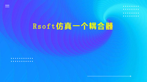
下面将介绍如在Rsoft软件中仿真一个耦合器。
打开Rsoft软件,导入耦合器的.ind 文件,即“File”->"Open"。
给耦合器设置路径,单击如图所示红 圈中的按钮。
在弹出的对话框中,单击“new"新建 一条路径,然后用鼠标在模型中选中 一条路径,如图所示。
继续单击”new“,并在模型中选择, 生成第2第3条路径。然后单击”ok“, 保存设置。
左图表示了本步片内 容为准。
单击模拟按钮,设置仿真的步长和结 果显示的方式,单击”ok“,便能看 到仿真的动态过程了。
谢谢观看
左图表示了本步骤的内容,以图片内 容为准。
给耦合器设置注入光,单击图中红圈 中的按钮。然后在弹出的对话框中设 置光从第三条路径注入。
左图表示了本步骤的内容,以图片内 容为准。
给耦合器添加监视器以观测仿真过程 中的耦合器功率变化情况。单击图中 红圈中的按钮,在弹出的对话框中分 别给三条路径都加上监视器。单 击”ok“保存。
Rsoft软件(BPM,光束传播法模拟)中文课件(第1-3章)江苏大学陈明阳教授编写 2018最新版

光通信器件设计江苏大学光电信息科学与工程系陈明阳2018.9主讲教师简历⏹陈明阳,博士,江苏大学教授,光电系系主任,江苏省“青蓝工程”培养对象。
博士论文曾获2006年度全国优秀博士学位论文提名奖,导师为我国集成光学创始人于荣金教授。
香港城市大学电子系访问研究员(2014-2015)。
⏹现为IEEE、OSA会员,中国光学学会高级会员,科技部重点研发计划项目、国家自然科学基金项目等评审专家。
⏹主要从事特种光纤结构设计及光纤技术应用等研究工作。
主持完成国家、省部级和横向课题10多项。
⏹发表论文70余篇,其中基于光束传播法应用方面的论文30多篇。
在Optics Letters、Optics Express、IEEE Photonics TechnologyLetters等国际光学期刊上发表SCI收录论文50余篇,其中SCI二区论文17篇。
论文总计被SCI引用500多次。
⏹获授权发明专利40余项,授权PCT专利(美国发明专利)2项(第一发明人)。
研究成果获省部级科技进步二等奖2项(排名第二和第四)。
主讲教师简历⏹近期光束传播法相关论文:⏹ 1. Investigation on adiabatic mode evolution in a few-modeoptical waveguide. Applied Physics B 2018, 124(5): 88.⏹ 2. Design of mode conversion waveguides based on adiabaticalmode evolution for mode division multiplexing. Applied PhysicsB 2017, 123(10): 256.⏹ 3. Design and optimization of fundamental mode filters based onlong-period fiber gratings.Opt. Fiber Technol.,2016, 30,89-94.⏹ 4. Mode-Selective Characteristics of an Optical Fiber With aHigh-Index Core and a Photonic Bandgap Cladding.2016, 22(2): 1-7.第一章绪论1. 学习内容Rsoft:基于光束传播法、时域有限差分法、传输矩阵法等,用于光波导器件设计和分析的专业软件2. 光器件数值模拟的意义⏹它为光器件研究提供一个低成本的试验空间和合理的实验方案;⏹通过数值模拟,可以进一步理解光波导的基本原理。
Rsoft软件简介和使用教程
RSOFT使用教程目录Rsoft简介 (3)Chapter 7 Tutorials 第七章教程 (5)Tutorial 1: Ring Resonator 教程1:环形共振器 (5)Device Layout: 器件结构: (5)Defining Variables 定义变量 (6)Drawing the Structure 画器件结构图 (6)Checking the Index Profile 核对折射率分布 (9)Adding Time Monitors 添加时间监视(探测)器 (10)Simulation: Pulsed Excitation 模拟:脉冲激发 (12)Launch Field 激发场 (12)Wavelength/Frequency Spectrum 波长/频率光谱 (12)Increasing the Resolution of the FFT 提高FFT的分辨率 (14)Simulation: CW Excitation 模拟:连续激发 (16)Tutorial 2: PBG Crystal: Square Lattice 教程 2:PBG 晶体:四方晶格 (17)Lattice layout 晶格布局 (17)Base Lattice Generation 基准晶格的创建 (17)Lattice Customization 定制晶格 (18)Checking the Index Profile 核对折射率分布 (18)Inserting Time Monitors 插入时间监视器 (19)Launch Set Up 激发场设置 (20)Simulation 模拟 (21)Data Analysis 数据分析 (22)Switching Polarization 改变偏振为TM模 (23)Periodic Boundary Condition Set Up (24)Tutorial 3: PBG Crystal: Tee Structure 教程 3:PBG晶体: T型结构 (24)Tutorial 4: PBG Crystal: Defect Mode 教程四:PBG 晶体:缺陷模型 (24)Rsoft简介包括BeamPROP、FullWAVE、BandSOLVE、GratingMOD、DiffractMOD、FemSIM, 以及MOST软件。
Rsoft软件(BPM,光束传播法模拟)中文课件(第1-3章)江苏大学陈明阳教授编写 2018最新版

光通信器件设计江苏大学光电信息科学与工程系陈明阳2018.9主讲教师简历⏹陈明阳,博士,江苏大学教授,光电系系主任,江苏省“青蓝工程”培养对象。
博士论文曾获2006年度全国优秀博士学位论文提名奖,导师为我国集成光学创始人于荣金教授。
香港城市大学电子系访问研究员(2014-2015)。
⏹现为IEEE、OSA会员,中国光学学会高级会员,科技部重点研发计划项目、国家自然科学基金项目等评审专家。
⏹主要从事特种光纤结构设计及光纤技术应用等研究工作。
主持完成国家、省部级和横向课题10多项。
⏹发表论文70余篇,其中基于光束传播法应用方面的论文30多篇。
在Optics Letters、Optics Express、IEEE Photonics TechnologyLetters等国际光学期刊上发表SCI收录论文50余篇,其中SCI二区论文17篇。
论文总计被SCI引用500多次。
⏹获授权发明专利40余项,授权PCT专利(美国发明专利)2项(第一发明人)。
研究成果获省部级科技进步二等奖2项(排名第二和第四)。
主讲教师简历⏹近期光束传播法相关论文:⏹ 1. Investigation on adiabatic mode evolution in a few-modeoptical waveguide. Applied Physics B 2018, 124(5): 88.⏹ 2. Design of mode conversion waveguides based on adiabaticalmode evolution for mode division multiplexing. Applied PhysicsB 2017, 123(10): 256.⏹ 3. Design and optimization of fundamental mode filters based onlong-period fiber gratings.Opt. Fiber Technol.,2016, 30,89-94.⏹ 4. Mode-Selective Characteristics of an Optical Fiber With aHigh-Index Core and a Photonic Bandgap Cladding.2016, 22(2): 1-7.第一章绪论1. 学习内容Rsoft:基于光束传播法、时域有限差分法、传输矩阵法等,用于光波导器件设计和分析的专业软件2. 光器件数值模拟的意义⏹它为光器件研究提供一个低成本的试验空间和合理的实验方案;⏹通过数值模拟,可以进一步理解光波导的基本原理。
Rsoft软件简介和使用教程

RSOFT使用教程目录Rsoft简介 (3)Chapter 7 Tutorials 第七章教程 (5)Tutorial 1: Ring Resonator 教程1:环形共振器 (5)Device Layout: 器件结构: (5)Defining Variables 定义变量 (6)Drawing the Structure 画器件结构图 (6)Checking the Index Profile 核对折射率分布 (9)Adding Time Monitors 添加时间监视(探测)器 (10)Simulation: Pulsed Excitation 模拟:脉冲激发 (12)Launch Field 激发场 (12)Wavelength/Frequency Spectrum 波长/频率光谱 (12)Increasing the Resolution of the FFT 提高FFT的分辨率 (14)Simulation: CW Excitation 模拟:连续激发 (16)Tutorial 2: PBG Crystal: Square Lattice 教程 2:PBG 晶体:四方晶格 (17)Lattice layout 晶格布局 (17)Base Lattice Generation 基准晶格的创建 (17)Lattice Customization 定制晶格 (18)Checking the Index Profile 核对折射率分布 (18)Inserting Time Monitors 插入时间监视器 (19)Launch Set Up 激发场设置 (20)Simulation 模拟 (21)Data Analysis 数据分析 (22)Switching Polarization 改变偏振为TM模 (23)Periodic Boundary Condition Set Up (24)Tutorial 3: PBG Crystal: Tee Structure 教程 3:PBG晶体: T型结构 (24)Tutorial 4: PBG Crystal: Defect Mode 教程四:PBG 晶体:缺陷模型 (24)Rsoft简介包括BeamPROP、FullWAVE、BandSOLVE、GratingMOD、DiffractMOD、FemSIM, 以及MOST软件。
Rsoft软件简介和使用教程

RSOFT使用教程目录Rsoft简介 (3)Chapter 7 Tutorials 第七章教程 (5)Tutorial 1: Ring Resonator 教程1:环形共振器 (5)Device Layout: 器件结构: (5)Defining Variables 定义变量 (6)Drawing the Structure 画器件结构图 (6)Checking the Index Profile 核对折射率分布 (9)Adding Time Monitors 添加时间监视(探测)器 (10)Simulation: Pulsed Excitation 模拟:脉冲激发 (12)Launch Field 激发场 (12)Wavelength/Frequency Spectrum 波长/频率光谱 (12)Increasing the Resolution of the FFT 提高FFT的分辨率 (14)Simulation: CW Excitation 模拟:连续激发 (16)Tutorial 2: PBG Crystal: Square Lattice 教程 2:PBG 晶体:四方晶格 (17)Lattice layout 晶格布局 (17)Base Lattice Generation 基准晶格的创建 (17)Lattice Customization 定制晶格 (18)Checking the Index Profile 核对折射率分布 (18)Inserting Time Monitors 插入时间监视器 (19)Launch Set Up 激发场设置 (20)Simulation 模拟 (21)Data Analysis 数据分析 (22)Switching Polarization 改变偏振为TM模 (23)Periodic Boundary Condition Set Up (24)Tutorial 3: PBG Crystal: Tee Structure 教程 3:PBG晶体: T型结构 (24)Tutorial 4: PBG Crystal: Defect Mode 教程四:PBG 晶体:缺陷模型 (24)Rsoft简介包括BeamPROP、FullWAVE、BandSOLVE、GratingMOD、DiffractMOD、FemSIM, 以及MOST软件。
- 1、下载文档前请自行甄别文档内容的完整性,平台不提供额外的编辑、内容补充、找答案等附加服务。
- 2、"仅部分预览"的文档,不可在线预览部分如存在完整性等问题,可反馈申请退款(可完整预览的文档不适用该条件!)。
- 3、如文档侵犯您的权益,请联系客服反馈,我们会尽快为您处理(人工客服工作时间:9:00-18:30)。
RSoft 仿真软件指导书
RSoft是一款非常实用的光波导仿真软件。
其中包含了BPM,FDTD,FEM等多种算法,使得它能够适用于各种不同要求场合。
本课程主要使用RSoft算法集中的BPM算法对光波导和简单光波导器件进行仿真计算,从而对光在波导中的传输有一定得了解。
一、软件CAD界面:
下载网站上的压缩包,解压缩后运行C:\Program Files\RSoft\bin文件夹中的bcadw32.exe,即出现如下图所示的CAD界面。
此界面是定义波导结构和下一步计算的前提。
二、单根波导的仿真:
在软件中,点击左上角的”New Circuit”按钮,如图所示。
点击后弹出基本设置对话框,波导的一些基本特性参数需要在此设定。
我们模拟目前光通信系统中应用最为广泛的掩埋型二氧化硅波导(channel型)。
波导横截面的尺寸结构为6um*6um,芯层折射率为1.465,包层折射率为1.455(包层和芯层的折射率差为0.01),通信波长为1.55um。
基本参数的设定如下图所示(注意,软件中关于长度的单位均为um):
设置完毕后点击”OK”,进入CAD界面。
首先画一根直波导。
点击”Segment mode”(新建文件时默认就是此模式),如上图红圈所示。
之后在空白的CAD窗口中某一处单击鼠标左键,在任意另一处再单击左键,即可画出一条波导,如下图所示。
到目前为止,画出的波导是任意的,我们还需要对它进行设置,满足我们设计的要求。
将鼠标移动至波导上(红色区域上),再单击鼠标右键,会弹出波导的设置菜单。
由于我们只需要仿真普通的直波导,所以大部分设置保持默认即可。
主要需要调整波导的位置。
在RSoft 软件中,波导位置是由首尾两个坐标确定的,并且BPM计算的光是只沿着z轴传播(即竖直方向),这个是需要特别注意的。
具体设置见下图。
设置完毕单击”OK”,就可以在CAD界面看到修改后的,沿着z轴、长度为1000um的波导(俯视图)。
单单如此还不够,我们还需要设置光源的特性和观察的路径。
首先设置路径,单击左侧工具栏中的”Edit Pathways”按钮。
单击后左侧工具栏会变成路径设置栏。
点击”New”按钮,会新建一个路径,再左键点击我们画好的波导,使路径与波导相一致(此时波导会变绿色),如下图:
然后再点击”Monitors”按钮,会弹出一个小对话框,设置一个与路径相匹配的探测器。
按照下图提示设置完后,点击对话框的”OK”按钮回到路径设置模式,再点击左侧的”OK”按钮回到画图模式。
再进行光源的设置。
单击左侧工具栏中的”Edit Launch Field”按钮,如下图。
单击后会弹出输入光源的设置对话框。
选取波导的基模即可。
如下图:
设置完成点击”OK”。
至此,模拟环境已基本设置完毕。
再模拟前,要需先将文件保存下来。
点击左上角”Save”按钮即可,注意在文件保存的路径中不允许出现空格和中文,请同学们务必注意!
模拟部分:
为了验证波导参数的正确性,而在CAD界面只看俯视图不能完全了解波导结构,我们还需要查看波导横截面的结构。
点击左侧工具栏下方的”Display Index Profile”按钮
会弹出对话框,选择Display Mode为”Contour Map (XY)”模式,
输入要保存文件的前缀名,并点击”OK”,即可看到波导横截面的折射率分布。
还可以进一步观察光在波导中传输时的分布情况。
单击左侧工具栏下方的”Compute Fundamental Mode”按钮,
在弹出的对话框中做如下设置:
输入要保存文件的前缀名,并点击”OK”,软件就开始进行模式的运算,最后会显示结果:
最后进行波导光传播的模拟。
点击左侧工具栏下方的”Perform Simulation”按钮,并按图进行参数设置,输入要保存文件的前缀名,最后点击”OK”.
最后仿真结果应如图所示:
三、定向耦合器的仿真:
Directional Coupler (定向耦合器)在光通信系统中应用非常广泛,既可以作为单独的器件,也可以作为其他器件的组成部分。
Directional coupler 最大的特点就是两根靠的很近的平行波导,光从其中一根波导输入,会在两根波导之间来回耦合。
其中光能量从一根波导耦合到另一根波导所需要的长度叫做耦合长度(Lc),见下图。
作业:
在熟悉了基本界面和操作之后,同学们需要根据题目的要求,自己设计一个马赫曾德调制器。
如下图:
马赫曾德型调制器的原理就是在某一条臂上加电压,导致折射率变化(如图中黄色的臂),使得两条臂中的光产生相位差,最后形成干涉。
干涉最大即为数字1,干涉最小即为数字0 题目:
波导的尺寸和折射率与之前的一致,通过调整黄色波导的折射率,来模拟电致折变。
用软件的扫描功能扫描黄色波导的折射率,求出输出光最小和最大时,分别对应的折射率。
