步进电机驱动器-ZD-M57P使用说明书
步进电机驱动器说明书

步进电机驱动器说明书DHBQ30722是基于DSP控制的三相步进电机驱动器。
它是将先进的DSP控制芯⽚和三相逆变驱动模块结合⼀起所构成的新⼀代数字步进电机驱动器。
驱动电压为AC110V-220V,适配电流在7.0A以下、外径57-130mm的各种型号的三相混合式步进电机。
该驱动器内部采⽤类似伺服控制原理的电路,此电路可以使电机运⾏平稳,⼏乎没有震动和噪⾳,电机在⾼速时,⼒矩⼤⼤⾼于⼆相和五相混合式步进电机。
定位精度最⾼可达60000步/转。
该产品⼴泛应⽤于雕刻机、中型数控机床、电脑绣花机、包装机械等分辨率较⾼的⼤、中型数控设备上。
特●⾼性能、低价格●设有16档等⾓度恒⼒矩细分,最⾼分辨率60000步/转●最⾼反应频率可达200Kpps●步进脉冲停⽌超过1.5s时,线圈电流⾃动减到设定电流的⼀半●光电隔离信号输⼊/输出●驱动电流1.2A/相到7.0A/相分16档可调●单电源输⼊,电压范围:AC110V-220V●相位记忆功能(注:输⼊停⽌超过3秒后,驱动器⾃动记忆当时电机相位,重新上电或MF信号由低电平变为⾼电平时,驱动器⾃动恢复电机相位)。
电流设定驱动器⼯作电流由DIP-1端⼦设定,运⾏电流为正常⼯作输出电流设置开关(详见下表)运⾏电流(A) 1.2 1.5 2.0 2.3 2.5 3.0 3.2 3.6 D1OFF OFF OFF OFF OFF OFF OFF OFF D2OFF OFF OFF OFF ON ON ON ON D3OFF OFF ON ON OFF OFF ON ON D4OFF ON OFF ON OFF ON OFF ON运⾏电流(A) 4.0 4.5 5.0 5.3 5.8 6.2 6.57.0 D1ON ON ON ON ON ON ON ON D2OFF OFF OFF OFF ON ON ON OND3OFF OFF ON ON OFF OFF ON ON D4OFF ON OFF ON OFF ON OFF ON细分设定驱动器细分由DIP-2端⼦设定,共16档,由6位拨码开关的前四位分别设定(后两位为功能设定)。
两相步进电机驱动器产品手册

两相步进电机驱动器产品手册1.产品介绍:1.1 产品概述:本章节介绍该两相步进电机驱动器产品的概览信息,包括产品的主要特点和应用领域。
1.2 产品规格:本章节详细介绍该步进电机驱动器的技术规格,包括输入电压、输出电流、步进角度等参数。
1.3 产品外观及接口:本章节描述该产品的外观特征以及接口定义,包括连接器类型、接口定义等。
2.安装与配置:2.1 安装步骤:本章节详细介绍该步进电机驱动器的安装步骤,包括硬件安装、接线和电源接入等。
2.2 配置参数:本章节介绍如何进行步进电机驱动器的参数配置,包括步数设置、步进角度调整等。
3.使用指南:3.1 驱动方式:本章节介绍两种常见的驱动方式,分别是全步进驱动和微步进驱动。
3.2 控制信号:本章节详细介绍控制信号的定义和使用方法,包括脉冲信号、方向信号等。
3.3 控制软件:本章节介绍常用的控制软件及其使用方法,包括设置步数、调整速度等。
3.4 常见问题解答:本章节了一些常见问题,并提供了相应的解决方案。
4.维护与保养:4.1 维护周期:本章节介绍了定期维护步进电机驱动器的时间周期,包括清洁、检查连接器等。
4.2 故障排除:本章节介绍了一些常见的故障现象并提供了相应的排除方法。
5.附件:本文档附带以下附件:●产品外观图●连接示意图●控制信号接口定义表6.法律名词及注释:在本文档中涉及的法律名词及其相关注释:●步进电机:一种电动机,它通过每次给定一个固定的角度脉冲就能转动一定角度的电动机。
●电流:通过导体中的电子流动而产生的一种物理现象。
●步进角度:步进电机每次转动的角度,通常为固定值(如1.8度)或可调节的微步角度。
步进电机控制器说明书

步进电机控制器说明书本文档旨在提供步进电机控制器的详细说明,包括其功能、使用方法和技术参数等内容。
以下是各章节的具体细化:1. 引言1.1 背景介绍1.2 目的与范围2. 控制器概述2.1 功能特点- 步进电机驱动能力强大,适用于多种应用场景。
- 支持多种通信接口(如RS485、CAN)以及常见编程语言(如C++、Python)。
- 提供丰富而灵活的运动控制模式。
3. 硬件配置要求3.1最低硬件需求CPU:Intel Core i5或更高版本;内存:8GB RAM 或以上;存储空间:100GB 可用磁盘空间;3.2推荐硬件配置CPU: Intel Core i7-9700K;内存:16 GB DDR4;显卡:NVIDIA GeForce RTX2060 Super;4.安装指南4-1安装前准备工作a) 操作系统选择:Windows操作系统推荐Windows10, Linux操作系統建议Ubuntu18+.b) 软件:访问官方网站最新版本的步进电机控制器软件。
4-2安装过程a) 运行安装程序,按照提示完成安装;b) 配置相关参数以适应实际需求。
5. 使用方法5.1 控制器连接与通信设置- 描述如何将控制器与计算机或其他设备进行连接,并配置相应的通信接口和参数。
5.2 步进电机驱动设置- 解释如何使用控制器来驱动步进电机,并提供示例代码和操作指南。
5.3 运动控制模式选择及调整-介绍不同运动模式(位置、速度等)的特点和用法,并说明如何根据需要进行调整。
6.技术规格6-1输入/输出端口提供输入/输出引脚定义表;描述各个引脚功能及其对应编号。
6—2总线协议支持列出所支持总线协议名称;指明每种总线协议在本系统中具体作用。
7.故障排除7_1常见问题解答常见问题并给予解决方案;8.附件:请参考附件文件。
法律名词及注释:1. 步进电机:一种将脉冲信号转换为角位移的执行器,通常由定子和转子组成。
2. 控制器:用于控制步进电机运动的设备或系统。
步进电机的应用—三相混合式步进电机驱动器使用说明书

三相混合式步进电机驱动器使用说明书1.特点★AC80~220V交流供电,能适应恶劣的电网环境★双极恒相流细分驱动★最大输出驱动电流6A/相(有效值,峰值达8A)★最大30000步/转的十六种细分模式可★过压、过流保护★输入信号光电隔离★可适应共阳、共阴、单/双脉冲多种模式★脱机保持功能★提供节能的自动半电流锁定功能2.性能指标供电电源80V~220VAC,容量0.8KVA输出电流有效值6A/相(峰值可达8A)(输出电流可由面板拨码开关设定)驱动方式恒相流PWM控制励磁方式400步/转,500步/转,600步/转,750步/转,1000步/转1500步/转,2000步/转,2500步/转,3000步/转,3750步/转5000步/转,6000步/转,7500步/转,10000步/转,15000步/转30000步/转绝缘电阻在常温常压下>500MΩ绝缘强度在常温常压下1KV,1分钟3.使用环境及参数冷却方式强制风冷使用环境场合尽量避免粉尘、油雾及腐蚀性气体温度0℃~+50℃湿度<80%RH,无凝露,无结霜震动 5.9m/s2Max保存温度-20℃~+65℃外形尺寸187×116×81mm重量 1.3Kg4.功能及使用★电源电压驱动器内部的开关电源设计保证了其可以适应较宽的电压范围,推荐使用80~220VAC,提高电压对提高电机的高速力矩有效,但是同时会加大运行噪音。
由于电机电磁感应回导致电机外壳生出一定的电荷,为确保使用者安全,请务必使用线径2mm2以上的机壳保护线和驱动器的机壳接地端子与保护大地可靠连接,并采用隔离变压器为驱动器供电★输出电流选择本驱动器采用双极恒流方式,最大输出电流值为6A/相(有效值),通过驱动器侧板第7,8四位开关的不同组合可以方便的选择4种电流值,从2A到6A(详见电流选择表),(注意:这里所说的电流是指驱动器每相输出电流的有效值,使用串电流表的方式不能得到正确的读数。
步进电机原理及使用说明
步进电机原理及使用说明一、前言2.4.1 步进电机概述步进电机是将电脉冲信号转变为角位移或线位移的开环控制元件。
在非超载的情况下,电机的转速、停止的位置只取决于脉冲信号的频率和脉冲数,而不受负载变化的影响,即给电机加一个脉冲信号,电机则转过一个步距角。
这一线性关系的存在,加上步进电机只有周期性的误差而无累积误差等特点。
使得在速度、位置等控制领域用步进电机来控制变的非常的简单。
虽然步进电机已被广泛地应用,但步进电机并不能象普通的直流电机,交流电机在常规下使用。
它必须由双环形脉冲信号、功率驱动电路等组成控制系统方可使用。
因此用好步进电机却非易事,它涉及到机械、电机、电子及计算机等许多专业知识。
步进电机是将给定的电脉冲信号转变为角位移或线位移的开环控制元件。
给定一个电脉冲信号,步进电机转子就转过相应的角度,这个角度就称作该步进电机的步距角。
目前常用步进电机的步距角大多为1.8度(俗称一步)或0.9度(俗称半步)。
以步距角为0.9度的进步电机来说,当我们给步进电机一个电脉冲信号,步进电机就转过0.9度;给两个脉冲信号,步进电机就转过1.8度。
以此类推,连续给定脉冲信号,步进电机就可以连续运转。
由于电脉冲信号与步进电机转角存在的这种线性关系,使得步进电机在速度控制、位置控制等方面得到了广泛的应用。
步进电机是一种将电脉冲转化为角位移的执行机构。
当步进驱动器接收到一个脉冲信号,它就驱动步进电机按设定的方向转动一个固定的角度(称为“步距角”),它的旋转是以固定的角度一步一步运行的。
可以通过控制脉冲个数来控制角位移量,从而达到准确定位的目的;同时可以通过控制脉冲频率来控制电机转动的速度和加速度,从而达到调速的目的。
步进电机可以作为一种控制用的特种电机,利用其没有积累误差(精度为100%)的特点,广泛应用于各种开环控制。
现在比较常用的步进电机包括反应式步进电机(VR)、永磁式步进电机(PM)、混合式步进电机(HB)和单相式步进电机等。
5相步进马达驱动器使用说明书

●電源逆接保護:輸入電壓極性接反時自動斷流
保護功能
●過電流保護:輸入電流超過額定值時自動斷流
●過熱保護:當驅動器超過 80˚ C 時自動斷流*2
燈號顯示
電源,TIMING
外形尺寸
90 (L) ×65 (W) ×32 (H)mm
重量
270g
使用環境溫度範圍
0 ˚ C ~ 40 ˚ C
*1. [a] 瞬間最大電壓為 40V,平常使用請勿超過 36V,以免造成驅動器損壞。
0
0.36
0.75
1
0.36
0.75
2
0.36
0.75
3
0.38
0.76
4
0.44
0.87
5
0.53
1.04
6
0.62
1.25
7
0.70
1.39
8
0.79
1.57
9
0.88
1.75
A
出廠設定值 0.97
出廠設定值 1.93
B
1.06
2.11
C
1.14
2.27
D
1.23
2.44
E
1.32
2.63
F
1.40
5 相馬達內部結線圖
泰映 TROY 出線 5 線 10 線
A 藍 藍/黑 B 紅 紅/棕 C 橙 紫/橙 D 綠 黃/綠 E 黑 白/灰
山洋電氣 SANYO DENKI 5 線 5*線 10 線
黑 藍 黑/黃 橙 紅 黑白/橙 藍 橙 橙白/藍 紅 綠 紅白/白 黃 黑 黃白/紅
多摩川 TAMAGAWA 5 線 10 線
過熱時會閃爍
全步進時 10 個脈波 LED 燈亮一次,
步进电机驱动器使用手册说明书

步进电机驱动器使用手册目录1安全事项 (2)2产品外形 (4)2.1产品外形 (4)3接口定义 (5)3.1电机、电源接口C N1 (5)3.1.1两相步进电机接线 (5)3.1.2五相步进电机接线 (6)3.2控制接口C N2 (7)3.2.1脉冲(P u l)信号/上限位信号 (9)3.2.2方向(D i r)信号/下限位信号 (9)3.2.3回零(Z e r o)信号/原点信号 (9)3.2.4脱机/使能(F r e e/E n a b l e)信号 (9)3.2.5到位(I N P)信号 (10)3.2.6就绪(R D Y)信号 (11)3.2.7接口电压 (11)3.3编码器接口C N3 (13)3.4U S B接口C N4 (14)3.5M o d b u s接口C N5 (15)4L E D指示 (16)4.1状态指示L E D (16)4.2通讯指示L E D (18)5性能参数 (18)5.1机械参数 (18)5.2安装尺寸 (19)6应用指南 (20)6.1安装准备 (20)6.2机械安装 (20)6.3电气安装 (21)6.4日常维护 (21)6.5注意事项 (21)6.5常见问题 (22)为保障使用者人身安全,保护设备正常使用,请务必阅读并遵守本章的安全事项。
在操作时违反本事项所示要求,可能会导致人员重伤或者死亡。
在操作时违反本事项所示要求,可能会引起驱动器永久损坏及附加事故。
谨防触电,爆炸或其他危险禁止在易爆、易燃或腐蚀性环境使用本产品;禁止开启产品外壳;驱动器带电时内部电压可能超过36VDC,驱动器和电机都必须接安全保护地线;驱动器内部电压不会瞬间释放,必须先切断电源,等指示灯熄灭后才能进行插拔、接线、设置、测量、搬动等人工操作;禁止带电插拔;驱动器故障时温度可能很高,必须先切断电源,等下降至安全温度后才能进行人工操作;驱动器应用于直接涉及人身安全的设备,必须配备人身安全防范措施;驱动器或设备故障时可能存在火灾隐患,必须配备消防安全防范措施。
步进电机驱动器的使与使用【范本模板】

步进电机驱动器的使用说明
二、步进电机驱动器的使用说明
本驱动器为M415B细分驱动器,适合驱动中小型的任何1。
5A相电流以下的两相或四相混合式步进电机.PUL为脉冲信号,通过控制脉冲的频率来控制步进电机的运行速度,DIR为方向控制。
通过细分设定来确定步进电机旋转一圈的脉冲数.
1.引脚信号定义
2.引脚信号功能的详解
3。
电气特性
4。
细分和电流设定
细分设定
改变驱动器的细分倍数,可改变电机旋转一圈所需的脉冲数
电流设定
对于同一电机,电流设定值越大时,电机的输出力矩越大,但电流大的同时电机和驱动器的发热也比较严重,所以一般情况是把电流设成供电机长期工作时出现温热但不过热的数值。
注意:电流设定后请运转电机15~30分钟,如电机温升太高,应降低电流设定值。
附:详情请参照M415B。
pdf。
北京时代超群电器 57 两相混合式驱动器说明书
57两相混合式驱动器使用说明书目 录第一章 概述 (1)第二章参数说明 (1)第三章安装尺寸............................................................. . (2)第四章 驱动器使用方法 (3)1.驱动器接线示意图 (3)2.使用步骤 (4)3.输入信号说明 (5)4.输入信号内部接口电路 (5)5.信号的电方式............................................................. .. (6)6.CP信号的脉冲宽度 (6)7. DIR信号起作用时刻 (6)8.电机升降速设计简介 (7)9.电机相电流设定 (7)10.细分设定 (7)第一章概述本款57两相混合式步进电机驱动器是BROTHER中的新产品,用于驱动两相或者四相混合式步进电机。
体积更小、性能更加稳定。
低频特性有很大提高。
第二章参数说明电流设定值: 0.45A,0.9A,1.35A,1.8A,2.25A,2.7A,3.15A每转步数: 200 (步距角1.8度)400 (步距角0.9度)800 (步距角0.45度)1600 (步距角0.225度)3200 (步距角0.1125度)6400 (步距角0.05625度)12800 (步距角0.028125度)输入脉冲方式: 单脉冲与双脉冲可选工作电源: DC20-40V一组配套电机: 42至57系列二相或四相混合式步进电机面板图 :第三章 按装尺寸第四章 驱动器使用方法 1.驱动器接线示意图图中标号释义:CP+:单脉冲模式,脉冲正输入端CP-:单脉冲模式,脉冲负输入端U/D+: 单脉冲模式,方向电平的正输入端 U/D-:单脉冲模式,方向电平的负输入端 CW+:双脉冲模式,正脉冲的正输入端 CW-:双脉冲模式,正脉冲的负输入端 CCW+:双脉冲模式,负脉冲的正输入端 CCW-:双脉冲模式,负脉冲的负输入端 PD+:脱机信号正输入端PD-:脱机信号负输入端电机与驱动接线2.使用步骤(1)参考面板提示,通过拨位开关设定您所需要的细分数,在CP脉冲能允许的情况下,尽量选用较大的细分数;(2)参考面板提示,通过拨位开关设定电机的相电流,一般设定为和电机额定相电流相,如果能够拖动负载,可以设定为小于电机额;定相电流,但不能设定为大于电机额定相电流;(3)驱动器在步进脉冲信号停止施加2秒左右,会自动进入半电流状态,这时电机相电流为运行时的一半,以减小功耗和保护电机。
步进电机驱动器使用说明
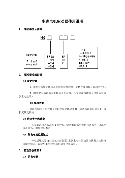
步进电机驱动器使用说明1.驱动器型号说明2.驱动器功能说明1)步距设置A.非细分型驱动器由步距控制信号控制,支持在线切换(即刻生效)。
B.细分型驱动器由面板拨动开关设置,不支持在线切换(设置后须重新上电生效)。
2)脱机控制脱机控制信号生效时(脱机控制光耦导通时)驱动器输出电流为0,电机无锁定转矩。
3)静止半电流锁定在无脉冲输入状态约1秒钟后,驱动器输出电流将自动减半,以减少电机发热,增加使用寿命。
4)停电电机位置记忆停电后驱动器自动记忆当前位置,重新上电时驱动器将恢复上次断电前输出状态,以避免上电时电机抖动和位置偏移。
3.驱动器使用要求1)供电电源我公司生产的系列步进电机驱动器都采用单电源供电,有直流、交流、交直流三种方式,随型号而异。
供电电源都支持宽电压范围。
供电电压的合适与否关系到步进电机的运行性能:A.低的电压有利于减少输出电流纹波,提高电机运行的平稳性,但较低的电压会影响电机的启动转矩和高频运行转矩,导致启动频率和最高运行频率降低。
B.偏小的电源容量(输出电流能力)也会影响电机高频运行转矩,并容易导致欠压保护。
C.为了使驱动器更可靠地工作,避免产生欠压、过压保护和损坏,在电压波动严重的情况下应该使用电源稳压器。
D.220V供电时须使用隔离变压器,同时进行可靠接地。
一般情况下用户应该使用驱动器标明的额定电压供电。
特殊情况要使用非额定电压的,必须保证电压在安全范围内。
2)电机接口A.驱动器和电机型号必须匹配,如三相混合式电机必须使用三相混合式驱动器,否则会导致工作异常甚至损坏驱动器和电机。
B.电机线必须和驱动器输出端子一一对应,否则会导致工作异常甚至损坏驱动器和电机。
C.电机额定电流必须和驱动器输出电流一致。
驱动器输出电流大于电机额定电流时会导致电机过热甚至烧坏,驱动器输出电流小于电机额定电流会导致输出转矩不足。
3)信号接口输入电压:3.5V< in V <9V输入电流:5mA< in I <20mA如果信号不在此范围内,须外接分压∕分流电阻 out R 使信号匹配。
步进电机驱动器说明书

1. How the motor controller control the motor speedIn the motor controller, there is a hardware timer T1 that is used to generate stepping pulse for stepper motor or reference position for servomotor. The input clock’s frequency of the timer, plus the preset value of this timer, determine the slewing speed of the motors.When T1 generates an interrupt, it mighto Drive the motor to move 1 step (1 micro-step or 1 encoder tick) for low speed slewing.o Drive the motor to move up to 32 steps for high speed slewing. This method applies to motor controller firmware version 2.xx. For motor controller with firmware 3.xx or above,the motor controller always drive the motor controller 1 steps/interrupt.2. Two motion modeGOTO mode: The master device tells the motor controller the desired destination, and then send a "Start" command. The motor controller will control the motor to move to that destination. The master device can check the motor status, real-time position, cancel the slewing during the GOTO. Speed(Tracking) mode: The master device calculate a proper preset value for T1 and send it to the motor controller, and then send a "Start" command. The motor controller will control the motor to slew at the desired speed. The master device can check the motor status, real-time position, cancel the slewing during the GOTO.There is a command which is used to select between the two motion mode for the next "Start"command. Generally, the motor should be at full stop status before setting the motion mode.Generally, the motor controller returns to "Speed Mode" when the motor stops automatically.A typical slewing session include:o Check whether the motor is in full stop status. If not, stop it.o Set the motion mode.o Set the parameters, for example, destination or preset value of T1.o Set the "Start" command.o For a GOTO slewing, check the motor status to confirm that the motor stops (Generally means arriving the destination. ). For a Speed mode slewing, send "Stop" command to endthe session.3. Calculation on Master DeviceA Skywatcher motor controller does not do complex calculation. The master device do it instead.Calculate the angleA Skywatcher motor controller only counts the step or the ticks of an incremental encoder on themotor shaft. But a master device can inquire the motor controller the resolution of the telescope axis (how many steps the telescope axis have for one revolution). We called it CPR (Counts per revolution). With CPR, the master device can convert an angle to steps or vise versa.Please note that CPR might be different for the two axes of a mount.Calculate the T1 preset value.A Skywatcher MC can report the T1’s input clock frequency TMR_Freq (Mention at the beginningof this article). A master device can use TMR_Freq and CPR to calculate the T1 preset value for desired motor speed.Speed_CountsPerSec = Speed_DegPerSec * CPR / 360T1_Preset = TMR_Freq / Speed_CountsPerSec= TMR_Freq * 360 / Speed_DegPerSec / CPRCalculate the T1 preset value for high speed slewingT1 preset value can be too small for high speed slewing, if T1’s input clock frequency is low. To solve this problem, the motor use a slightly different way to control motor speed when highspeed slewing is required (For example, move an axis with higher then 128x sidereal rate). When T1 generates an interrupt, the motor controller moves N micro-steps for a stepper motor, orchange the reference position for N steps for a DC servo motor. That means, for the same T1preset value, the motor will run N times faster than changing only 1 steps for each T1 interrupt event.Currently, N is a fixed number, and a master device can inquire the motor controller for it. Itmight be 16, 32 or 64.The formula for calculating T1 preset value for high speed slewing is:T1_Preset = N * TMR_Freq * 360 / Speed_DegPerSec / CPRWhen a master wants an axis to slew at high speed, it should let the motor controller know when it configures the motor to the Speed (Tracking) Mode. For GOTO mode, the motor controller will take care of it automatically.4. Command Format:The command always starts with a ":" character and ends with a carriage return character 0x0D.If a second ":" character is received by the motor controller before the carriage return character, then the motor controller will abandon the characters received and starts receiving a newcommand.Motor controller will process the command and send response after it receives the carriage return character.A response from the motor controller always starts with a "=" character and ends with a carriagereturn character, if the response is normal.If there is something wrong, the motor will response a message starts with a "!" character, followed by error code and a carriage return character.All the character in the command and the response are ASCII characters.A command from the master device has the following parts:o1 byte Leading character: ":"o1 byte command word, check command set table for detailso1 byte channel word: "1" for RA/Az axis; "2" for Dec/Alt axis.o1 to 6 bytes of data, depending on command word: character "0" to "9", "A" to "F"o1 byte Ending character: carriage return character.A normal response from the motor controller has the following parts:o1 byte Leading character: "="o1 to 6 bytes of data, depending on which command is processed: "0" to "9", "A" to "F"o1 byte Ending character: carriage return character.An abnormal response from the motor controller has the following parts:o1 byte Leading character: "!"o2 bytes of error code: "0" to "9", "A" to "F"o1 byte Ending character: carriage return character.Data format:o24 bits Data Sample: for HEX number 0x123456, in the data segment of a command orresponse, it is sent/received in this order: "5" "6" "3" "4" "1" "2".o16 bits Data Sample: For HEX number 0x1234, in the data segment of a command or response, it is sent/received in this order: "3" "4" "1" "2".o8 bits Data Sample: For HEX number 0x12, in the data segment of a command or response, it is sent/received in this order: "1" "2".5. Command Set6. HardwareUART: 9600bps, 1 start bit, 1 stop bit, no parity check.Signal level: 5V or 3.3V.On most of the EQ mount, the TX and RX lines are separated. The motor controller will send its response immediately after it received and process the command.On most the Alt/Az mount, TX and RX lines are connected together, and there is another line(Drop) to indicate that the TX/RX bus is busy. The Drop line is controlled by the master only, which means the master device should pull the Drop line to low level when it starts to send acommand and keep pulling it low until it receives the full response from the motor controller, or,a time-out occurs. The motor controller will send its response immediately after it received andprocess the command, thus the master device should release the TX/RX bus as soon as possible after the last bit of the command is shift out of the hardware register.The motor controller pull its TX line to high level with a 5.1K to 10K resistor, other than that, it does not strongly pull the TX line to high level and other devices can pull the TX line to low level without problem.6. Wi-Fi ConnectionThe same protocol runs on the SynScan Wi-Fi dongle or mount with built-in Wi-Fi module.The Wi-Fi dongle/module runs a UDP server and listen to UDP port 11880 to accept commands from host.The command must be sent in a single UDP package; the response is also included in a single package.When the Wi-Fi dongle/module works in access point mount, its IP address is 192.168.4.1. If it runs in station mode, the router that it links to allocates its IP address.6. Useful ResourcesSample Code: https:///archive/p/skywatcher/Documents: /download/manual/application-development/。
电机驱动器说明

f
3
0
p
C
1
1
1 7 2 0 7 5 3
8
1 6
0
L298N
U
p
G
EN
B
EN
A
IN4
IN3
IN2
IN1
2
C
N 6
D 11.0592M
ISEN
B
ISEN
A
OUT4
OUT3
OUT2
OUT1
VSS
V
S
1
1
1
1
3
2
4
9
5
4
3
+5V 1
2
+5V
Download
3
4
+12V
5
6
7
8
9
ቤተ መጻሕፍቲ ባይዱ
1 0
2
1N4007
D
1N4007
P2.0
1
C
0 3
4
LM1
P1.3
P1.2
P1.1
P1.0
Vin
G
N
D Vout
LED4
LED3
LED2
LED1
220UF
LIP4
LIP3
LIP2
LIP1
C
2
+5V
LIP1 R-2
1
2 LIP2
1
2
1
2
1
2
1
1
C
2
0 4
TLP4 LIP3
TLP3
TLP2
TLP1
4
3
LIP4
4
1
步进电机驱动器使用说明

l 外形图
SW6
D45
SW5 SW4
SW3
SW2
Alarm Power
SW1
B+ BA+ A-
拨码开关X
电机 X
Alarm
DIR
CP
GND
Vcc
DIR CP
信号输入端
5V
B+
B-
电机Y
A+
A-
SW6
SW5
SW4
SW3
SW2
拨码开关Y
SW1
注:拨码开关的标号可能和上图标识不一致,以上图标识的位置为准。
4A 3A 2.5A 2A 1.7A 1.5A 1.2A 0.8A
l 细分状态
SW1
0 (ON) 0 (ON) 1 (OFF) 1 (OFF)
SW2
0 (ON) 1 (OFF) 0 (OFF) 1 (OFF)
l 电机接线
细分数 20 32 40 64
l 拨码开关定义
工作W6 SW5 SW4 SW3 SW2 SW1
l 电流设定端
SW6
OFF ON OFF OFF ON ON OFF ON
SW5
OFF OFF ON OFF ON OFF ON ON
SW4
OFF OFF OFF ON OFF ON ON ON
额定电流
一般用途中应将sw4设成秒左右电流自动减至一半左右实际值的6信号接口cp为控制脉冲信号端脉冲频率最高1khz脉冲宽度最小4时电机反转
步进电机驱动器使用说明
l 驱动器功能说明
驱动器功能
操作说明
微步细分数设定 输出电流设定 自动半流功能
信号接口 电机接口 电源接口 指示灯 安装说明
步进电机控制器说明书
步进电机可编程控制器使用说明一、系统特点●控制轴数:单轴;●指令特点:任意可编程(可实现各种复杂运行:定位控制和非定位控制);●最高输出频率:40KHz(特别适合控制细分驱动器);●输出频率分辨率:1Hz;●编程条数:99条;●输入点:6个(光电隔离);●输出点:3个(光电隔离);●一次连续位移范围:—7999999~7999999;●工作状态:自动运行状态,手动运行状态,程序编辑状态,参数设定状态;●升降速曲线:2条(最优化);●显示功能位数:8位数码管显示、手动/自动状态显示、运行/停止状态显示、步数/计数值/程序显示、编辑程序,参数显示、输入/输出状态显示、CP脉冲和方向显示;●自动运行功能:可编辑,通过面板按键和加在端子的电平可控制自动运行的启动和停止;●手动运行功能:可调整位置(手动的点动速度和点动步数可设定);●参数设定功能:可设定起跳频率、升降速曲线、反向间隙、手动长度、手动速度、中断跳转行号和回零速度;●程序编辑功能:可任意插入、删除可修改程序。
具有跳转行号、数据判零、语句条数超长和超短的判断功能;●回零点功能:可双向自动回到零点;●编程指令:共14条指令;●外操作功能:通过参数设定和编程,在A操作和B操作端子上加开关可执行外部中断操作;●电源:AC220V(电源误差不大于±15%)。
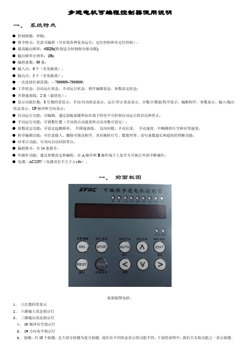
一、前面板图前面板图包括:1、八位数码管显示2、六路输入状态指示灯3、三路输出状态指示灯4、 CP脉冲信号指示灯5、 CW方向电平指示灯6、按键:共10个按键,且大部分按键为复合按键,他们在不同状态表示的功能不同,下面的说明中,我们只去取功能之一表示按键。
后面板图及信号说明:后面板图为接线端子,包括:1、 CP、CW、OPTP为步进电机驱动器控制线,此三端分别连至驱动器的相应端,其中:CP————步进脉冲信号CW————电机转向电平信号OPTO————前两路信号的公共阳端CP、CW的状态分别对应面板上的指示灯2、启动:启动程序自动运行,相当于面板上的启动键。
步进电机说明书
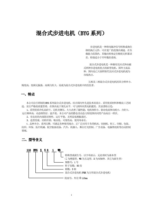
混合式步进电机(BYG系列)步进电机是一种将电脉冲信号转换成角位移的执行元件,可在宽广的范围内调速。
在负载能力范围内,其输出转角定位精度无积累误差,特别适合于开环数控系统。
混合式步进电机是一种兼有反应式和永磁式两种步进电机优点的新型电机,国外主流品种,国内也已大面积取代反应式步进电机成为市场热点。
五相及三相混合式步进电机因其分辨率小,精度高,低频无振荡,高频力矩大,而成为混合式步进电机中的佼佼者。
一、特点本公司自行研制的BYG系列混合式步进电机,结合国内外先进技术而设计,采用优质材料和精良工艺制造,实行严格的质量管理,在国内处于领先水平,可与国外同类电机媲美。
其显著特点是:1、采用优质冷轧高矽片,无机壳铆压,大大改善了磁性能;电机体积小,驱动电流和功耗小,力矩大,运行频率高,动态特性好,温升低。
本公司产品的静态及动态力矩较国内同类产品高出一档次。
2、有良好的内部阻尼特性,运行平稳,无明显低频振荡区。
3、造型美观,结构牢固,噪音低,可靠性高,使用寿命长。
4、品种齐全,系列完整,可满足各种使用场合。
正广泛应用于各类机床,切割机,轻工、印刷、包装、纺织、环保、医疗机械,航空航海设备,汽车,机器人,舞台灯光控制、广告设备,电脑绣花机等自动控制领域。
二、型号含义110 BYG 5 5 0 1 WB特殊型或派生号,以字母表示,无此项时为基本型(Z为增强型,WB为五边型,D为双轴伸,其它为派生型)规格号:1号转子齿数:50齿相数:5相混合式步进电机(FHB为方形混合式步进电机)机座号:外径φ110mm三、产品系列及性能参数1.方形电机系列2.圆形电机系列注:1、打 * 者为正在开发的新产品,可供期货;型号后有“Z”者为增强型。
2、二相电机为四引出线,四相电机为八引出线,除出线方式不同外,其余参数性能完全一样,配本公司驱动电源时用二相电机。
四相电机可改接成二相电机,有串联、并联及单极性三种接法,按并联接法时,相电流应加倍,四相电机用并联接法时,高速性能要优于其它接法。
步进电机的使用
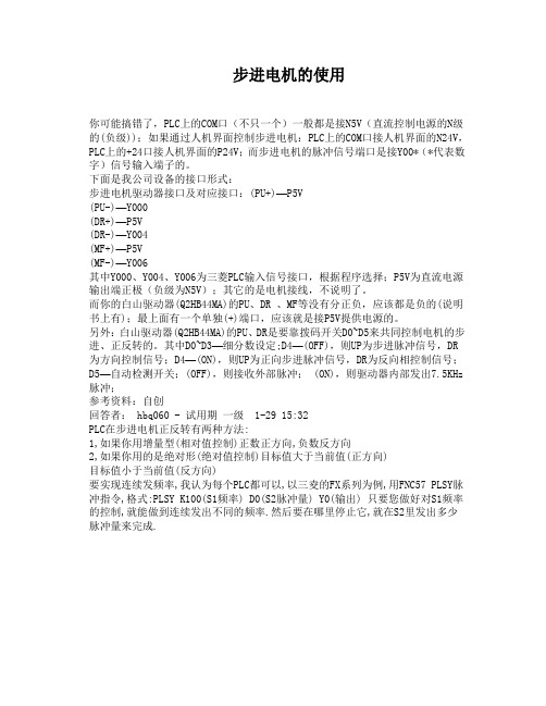
步进电机的使用你可能搞错了,PLC上的COM口(不只一个)一般都是接N5V(直流控制电源的N级的(负级));如果通过人机界面控制步进电机:PLC上的COM口接人机界面的N24V,PLC上的+24口接人机界面的P24V;而步进电机的脉冲信号端口是接Y00*(*代表数字)信号输入端子的。
下面是我公司设备的接口形式:步进电机驱动器接口及对应接口:(PU+)—P5V(PU-)—Y000(DR+)—P5V(DR-)—Y004(MF+)—P5V(MF-)—Y006其中Y000、Y004、Y006为三菱PLC输入信号接口,根据程序选择;P5V为直流电源输出端正极(负级为N5V);其它的是电机接线,不说明了。
而你的白山驱动器(Q2HB44MA)的PU、DR 、MF等没有分正负,应该都是负的(说明书上有);最上面有一个单独(+)端口,应该就是接P5V提供电源的。
另外:白山驱动器(Q2HB44MA)的PU、DR是要靠拨码开关D0~D5来共同控制电机的步进、正反转的。
其中D0~D3—细分数设定;D4—(OFF),则UP为步进脉冲信号,DR 为方向控制信号;D4—(ON),则UP为正向步进脉冲信号,DR为反向相控制信号;D5—自动检测开关;(OFF),则接收外部脉冲; (ON),则驱动器内部发出7.5KHz 脉冲;参考资料:自创回答者: hbq060 - 试用期一级 1-29 15:32PLC在步进电机正反转有两种方法:1,如果你用增量型(相对值控制)正数正方向,负数反方向2,如果你用的是绝对形(绝对值控制)目标值大于当前值(正方向)目标值小于当前值(反方向)要实现连续发频率,我认为每个PLC都可以,以三夌的FX系列为例,用FNC57 PLSY脉冲指令,格式:PLSY K100(S1频率) D0(S2脉冲量) Y0(输出) 只要您做好对S1频率的控制,就能做到连续发出不同的频率.然后要在哪里停止它,就在S2里发出多少脉冲量来完成.。
57系列数字式一体化混合伺服驱动器使用说明书-步进电机
57 系列 数字式一体化混合伺服驱动器 使用说明书
目录
一、产品简介................................................................................................................2 1. 概述...........................................................................................................................2 2. 特点...........................................................................................................................2 3. 应用领域...................................................................................................................2 二、电气、机械和环境指标....................................................................................... 3 1. 电气指标...................................................................................................................3 2. 使用环境及参数................................................................3 3. 机械结构尺寸图.......................................................................................................3 4. 散热注意事项...........................................................................................................4 三、驱动器接口和接线介绍....................................................................................... 4 1. 接口描述...................................................................................................................4 2. 控制信号接口电路...................................................................................................5 3. 控制信号时序图.......................................................................................................5 4. 控制信号模式设置...................................................................................................5 5. 接线要求...................................................................................................................5 四、拨码开关设定....................................................................................................... 6 五、保护功能................................................................................................................6 六、常见问题..............................................................................................................11 1.应用中常见问题和处理方法...................................................................................11 2.驱动器常见问题答用户问答...................................................................................11 深圳市美蓓亚斯科技有限公司产品保修条款.........................................................12
步进电机介绍和功能说明书
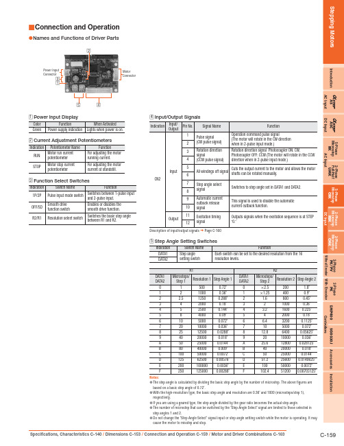
IntroductionASASC5-Phase Microstep RK 2-Phase Full/Half UMK 5-Phase Microstep CRK 2-Phase Microstep RBK 2-Phase Microstep CMK2-Phase PK/PV 2-Phase PK EMP400SG8030J Accessories Installation AC InputDC InputAC InputDC InputWithout Encoder With Encoder ControllersConnection and Operation■Names and Functions of Driver Parts●ConnectorMotorConnector□5□4124Description of input/output signals ➜ Page C-1605Notes:The step angle is calculated by dividing the basic step angle by the number of microstep. The above figures are ●based on a basic step angle of 0.72˚.With the high-resolution type, the basic step angle and resolution are 0.36˚ and 1000 (microsteps/step 1), ●respectively.If you are using a geared type, the step angle divided by the gear ratio becomes the actual step angle.●The number of microstep that can be switched by the "Step Angle Select" signal are limited to those selected in ●step angles 1 and 2.Do not change the "Step Angle Select" signal input or step angle setting switch while the motor is operating. It may ●cause the motor to misstep and stop.Connection Diagram●DriverControllerInput Signal Connection◇Signals can be connected directly when 5 VDC is supplied. If the signals are used at a voltageexceeding 5 VDC, be sure to provide an external resistor to prevent the current exceeding 20 mA from flowing. Internal components will be damaged if a voltage exceeding 5 VDC is supplied directly without using an external resistor.Example: If the voltage is 24 VDC, connect a resistor (R 1) of 1.5 to 2.2 k Ω and 0.5 W or more.Output Signal Connection◇Use output signals at 24 VDC or less and 10 mA or less.If these specifications are exceeded, the internal components may be damaged.Check the specification of the connected equipment.When the current is above 10 mA, connect an external resistor R 2.Power Supply◇Use a power supply that can supply sufficient input current. When power supply capacity is insufficient, a decrease in motor output can cause the following malfunctions:Motor does not operate properly at high-speed ●Slow motor startup and stopping●Notes on Wiring◇Use twisted-pair wires of AWG24 ●∼22 and keep wiring as short as possible [within 2 m (6.6 ft.)].Note that as the length of the pulse signal line increases, the maximum transmission frequency ●decreases. Technical reference ➜ Page F-54Use wires of AWG22 or thicker for the power supply lines. When assembling the connector, ●use the hand-operated crimp tool or the crimped driver lead wire set (sold separately). The crimp tool is not provided with the package. It must be purchased separately.Provide a minimum distance of 2 cm (0.79 in.) between the signal lines and power lines (AC ●lines, motor lines and other large-current circuits).Do not run the signal lines in the same duct as power lines or bundle them with power lines.If noise generated by the motor lead wires causes a problem, insert ferrite cores in the motor ●lead wire.Incorrect connection of DC power input will lead to driver damage. Make sure that the polarity ●is correct before turning power on.IntroductionASASC5-Phase Microstep RK 2-Phase Full/Half UMK 5-Phase Microstep CRK2-Phase Microstep RBK 2-Phase Microstep CMK2-Phase PK/PV 2-Phase PK EMP400SG8030JAccessoriesInstallationAC Input DC InputAC Input DC InputWithout Encoder With EncoderControllersStep Angle Select (C/S) Input Signal◇You may select two step angles (resolutions) from 16 available ●step angles (resolutions) with the step angle setting switches DATA1 and DATA2.When the signal is at "photocoupler OFF ," a step angle set by ●DATA1 is selected; at "photocoupler ON," DATA2 is selected.Example: Changing the step angle from 0.072˚ to 0.72˚.Step Angle Select CW Pulse MotorON OFF (DATA1)(DATA2)10 Pulses1 PulseBe sure to change step angle select inputs only when the pulse ●signals are at rest. Switching while moving may cause a positional error of the motor.When the step angle is changed by the "Step Angle Select" signal, ●the "Excitation Timing" signal output may become impossible for some combinations of step angles. When the "Excitation Timing" signal is used, adjust the number of pulses so that the motor can operate with angles that are multiples of 7.2˚.Example:After moving 9 pulses with 0.072˚/step setting, change the step angle to 0.72˚/step and move 1 pulse. In this case, "Excitation Timing" signal will not be output because the step "0" position is skipped.Operate 9 pulses with 0.072˚/step Operate 1 pulse with 0.72˚/step STEP "0""Excitation Timing" signal is only output at step "0" position.✽Automatic Current Cutback Release (C.D.INH) Input Signal ◇When this signal is in the "photocoupler ON" state, the automatic●current cutback function is disabled. When this signal is in the"photocoupler OFF" state, the automatic current cutback function will be activated after the motor stops (after approximately 100 msec).The photocoupler must be "OFF" except when the running current ●is adjusted.Excitation Timing (TIMING) Output Signal Output Circuit and Sample Connection◇The "Excitation Timing" signal is output to indicate when the motor ●excitation is in the initial stage (step "0" at power up).The "Excitation Timing" signal is output simultaneously with a ●pulse input each time the excitation sequence returns to step "0." The excitation sequence will complete one cycle for every 7.2˚ rotation of the motor output shaft.Microsteps/step 1: Signal is output once every 10 pulses. Microsteps/step 10: Signal is output once every 100 pulses.Timing chart at 0.72˚/step (Microsteps/step 1)When connected as shown in the sample connection, the signal will be "photocoupler ON" at ✽step "0."Pulse Input Rotation DirectionInputON OFF ON OFF ON OFF Excitation TimingOutput ✽Note:When power is turned ON, the excitation sequence is reset to step "0" and the "Excitation ●Timing" signal is output.Timing Chart●MotorPower Input2-Pulse Input Mode1-Pulse Input ModeRotation DirectionInput Signal Pulse Input SignalCW Pulse Input Signal CCW Pulse Input SignalAll Windings OffInput Signal Step Angle SelectInput SignalON OFF ON OFF ON OFFONOFFON OFF ON OFF ON OFFCW CCW1 ✽T he minimum switching time to change direction (1-pulse input mode), and switching time to change CW, CCW pulse (2-pulse input mode) 10 μs is shown as a response time of circuit. The motor may need more time than that.2 ✽D epends on load inertia, load torque and starting frequency.3 ✽N ever input a pulse signal immediately after switching the "All Windings Off" signal to the "photocoupler OFF" state. The motor may not start.4 ✽W ait at least 5 seconds before turning on the power again.Adjusting the Current ■Adjusting the Motor Current●Use the "RUN" potentiometer to decrease the current and suppress the temperature rise in the motor/driver, or when there is sufficient motor torque and you want to suppress vibration by lowering the current.Use the "STOP" potentiometer to readjust the current at motor standstill in relation to the holding-brake force of the motor.Factory settingsRunning current: Rated currentCurrent at motor standstill: 50% of rated currentFollow the procedure below to adjust the motor current. Connecting an Ammeter◇Connect a DC ammeter as illustrated below.Connect a DC ammeter in series to the blue motor lead wireand motor connector pin No. 1. Set all driver input signals to the "photocoupler OFF" state.Disconnect the red motor lead wire from connector pin No. 2, and black motor lead wire from connector pin No. 5.Note:Do not input pulse signals.●Electric shock may result if the red and black motor lead wires contact each other. Insulate ✽these motor lead wires to prevent electric shock.Adjusting the Motor Running Current◇To adjust the motor running current, follow the procedure below:1. S et the automatic current cutback release signal to the"photocoupler ON" state. Keep other signals in the "photocoupler OFF" state.2. Turn on the power to the driver.3. U se the "RUN" potentiometer to adjust the motor running current.4. W hen the power is turned on, the value measured by the ammeterrepresents the total current in two phases through the blue motor lead wire. The current for one phase is equivalent to one-half the ammeter value. (Example: To set the current to 1.0 A/phase, adjust the current level until the ammeter reads 2.0 A.)5. W hen the running current has been adjusted, set the automaticcurrent cutback release signal to the "photocoupler OFF" state. Notes:Be sure to use the motor at the rated current or below.●Adjusting the running current will also change the current at standstill.●Adjusting the Current at Motor Standstill◇To adjust the current at motor standstill, follow the procedure below: 1. S et the automatic current cutback release signal to the"photocoupler OFF" state. Keep other signals in the"photocoupler OFF" state.2. Turn on the power to the driver.3. U se the "STOP" potentiometer to adjust the motor current atstandstill.4. W hen the power is turned on, the value measured by the ammeterrepresents the total current in two phases through the blue motor lead wire. The current for one phase is equivalent to one-half the ammeter value. (Example: To set the current to 0.5 A/phase, adjust the current level until the ammeter reads 1.0 A.)Holding Torque[N·m (oz-in)]Maximum Holding Torque [N·m (oz-in)]×Current at Standstill[A]Motor Rated Current [A]=Notes:Always set the running current first, turn off the driver power and turn it back on, and then set ●the current at standstill. Setting the running current after current at standstill may change the current setting at standstill.Setting the current at motor standstill too low may affect the starting of the motor or the●position-holding action.。
- 1、下载文档前请自行甄别文档内容的完整性,平台不提供额外的编辑、内容补充、找答案等附加服务。
- 2、"仅部分预览"的文档,不可在线预览部分如存在完整性等问题,可反馈申请退款(可完整预览的文档不适用该条件!)。
- 3、如文档侵犯您的权益,请联系客服反馈,我们会尽快为您处理(人工客服工作时间:9:00-18:30)。
Indexer接口步进电机驱动器
使用说明书
(57型:ZD-M57P)
版本 说明
Ver1.00 初始
1.产品特点
☆微型设计,安装便利,可与57步进电机一体化
☆散热铸铝封闭型外壳
☆停止运行时自动半流,无锁相噪声
☆并行接口高速光电隔离,兼容3.3-5V和12-24V逻辑电平☆电流2-4.5A连续可调
☆ 1/2/4/8/16/32/64/128细分可选
2.产品参数
供电电源 DC11V-DC36V/5A,推荐DC24V
Indexer 接口COM 共阳极。
拨码开关选择3.3V-5V或者12V-24V
说明:拨码开关HV选择On位置时,COM可当共阴极使用DIR 0V或者Vcom。
电流:8mA@3.3V/8mA@12V/15mA@5V/18mA@24V
STP 0V或者Vcom。
电流:8mA@3.3V/8mA@12V/15mA@5V/18mA@24V
频率0-20KHz
EN 0V或者Vcom。
电流:8mA@3.3V/8mA@12V/15mA@5V/18mA@24V
Vcom或者悬空,EN使能步进电机;0V步进电机脱机状态输出电机电流峰值4.5A(单相最大),实际使用2-4.5A可调
驱动方式 PWM斩波恒流
驱动细分拨码开关设置选择1、2、4、8、16、32、64、128
绝缘电阻在常温常压下>100MΩ
绝缘强度在常温常压下0.5KV , 1 分钟
保护输入反接、过载、驱动过热、驱动过流
操作温度 -20℃-85℃
3.电气接口
Ref之间电压。
相电流值 = 电压值数值×2
例如:步进电机相电流为4.0A,调节
电位器,是的Ref与GND之
间电压为2.0V
4.典型接线图
兼容3.3V-5V和12V-24V用户级,脱机信号可选接。
注意:用户系统使用3.3V-5V时,拨码开关HV拨到ON(见3电气接口)用户系统使用12V-24V时,拨码开关HV拨到OFF
5.包装
序号数量部件
1 1 ZD-M57P并行接口57型步进电机驱动器一个
2 1 5264-6P延长线30cm
3 4(选)φ3×1
4 螺钉
驱动器与57步进电机孔位、大小一致。
控制器可以与57步进电机一体化安装
※注意※:驱动器与电机一体化安装前,先将驱动器输出相电流电流调整与电机标注电流一致!。
