ET200组态工具手册
et200m使用手册
et200m使用手册
ET200M是西门子公司生产的一款工业自动化模块,用于控制和
监视工业过程。
它包括数字输入/输出模块、模拟输入/输出模块、
通信模块等,可以灵活地配置和扩展,适用于各种工业自动化场景。
ET200M模块的使用手册通常包括以下内容:
1. 产品概述,介绍ET200M模块的基本特性、功能和应用范围,帮助用户了解该产品的基本情况。
2. 安装与接线,详细介绍ET200M模块的安装方法和接线要求,包括模块的安装位置、接线方式、接地要求等,帮助用户正确地安
装和连接模块。
3. 系统配置,介绍如何进行ET200M模块的系统配置,包括模
块的地址分配、参数设置、总线配置等,帮助用户正确地配置
ET200M模块。
4. 编程与调试,介绍如何使用编程软件对ET200M模块进行编
程和调试,包括PLC编程、通信配置、故障诊断等,帮助用户正确
地编写和调试控制程序。
5. 维护与保养,介绍ET200M模块的日常维护和保养方法,包括清洁、温度检测、电源检测等,帮助用户正确地进行模块的维护和保养工作。
6. 故障排除,介绍ET200M模块常见故障的排除方法,包括故障代码的解析、故障现象的分析、故障原因的排查等,帮助用户快速地排除模块故障。
7. 规格参数,列出ET200M模块的详细规格参数,包括输入/输出点数、通信速率、工作温度等,帮助用户了解模块的具体性能指标。
总的来说,ET200M模块的使用手册是用户正确、安全、高效地使用该产品的重要参考资料,用户在使用ET200M模块时应该仔细阅读并严格按照手册的要求进行操作。
希望这些信息能够帮助你更好地了解ET200M模块的使用手册。
西门子(Siemens)ET200SP AS-i Master在TIA中的使用入门说明书

22016/CN/view/zh/109483381C o p y r i g h t ãS i e m e n s A G C o p y r i g h t y e a r A l l r i g h t s r e s e r v e d目录1简介 .................................................................................................................... 31.1AS-i 通信协议简介 ............................................................................... 31.2网络结构 .............................................................................................. 41.3扩展距离 . (62)1500CPU+ET200SP AS-i 通信 .......................................................................... 82.1硬件和软件需求 ................................................................................... 82.2硬件组态 .............................................................................................. 92.3IO 访问方法 ....................................................................................... 132.4通信测试 ............................................................................................ 162.4.1OB1编程 ........................................................................................... 162.4.2读取AS-i 从站配置 ............................................................................ 162.4.3IO 访问测试 (173)修改 AS-i 从站地址 ........................................................................................... 183.1使用编址器 ........................................................................................ 183.2通过“在线和诊断”设置 AS-i 从站地址 ................................................. 183.3通过编程方式 . (224)诊断 .................................................................................................................. 254.1通过 CM AS-i Master 指示灯诊断 ...................................................... 254.2通过“在线和诊断”查看模块信息 ......................................................... 254.3通过命令读取 AS-i 从站状态列表 . (255)300CPU+ET200SP AS-i 通信 (286)ET200SP CM AS-i Master 固件版本 ................................................................ 296.1将AS-i Master 模块组态为V1.1版本 ................................................ 296.2升级AS-i Master 模块为V1.1版本 . (317)参考资料 (32)C o p y r i g h t ãS i e m e n sA G C o p y r i g h t y e a r A l l r i g h t s r e s e r v e d 1简介AS-i (actuator sensor interface )是传感器/执行器接口的缩写。
SIMATIC ET 200SP TM PosInput 1 数据手册说明书

General information Product type designation Firmware version ● FW update possible usable BaseUnits Color code for module-specific color identification plate Product function ● I&M data ● Isochronous mode Engineering with ● STEP 7 TIA Portal configurable/integrated from version ● STEP 7 configurable/integrated from version ● PROFIBUS from GSD version/GSD revision ● PROFINET from GSD version/GSD revision
5/9/2023
Subject to change without notice © Copyright Siemens
Automatic encoding ● Mechanical coding element ● Type of mechanical coding element
Digital inputs Number of digital inputs Digital inputs, parameterizable Input characteristic curve in accordance with IEC 61131, type 3 Digital input functions, parameterizable ● Gate start/stop ● Capture ● Synchronization ● Freely usable digital input Input voltage ● Rated value (DC) ● for signal "0" ● for signal "1" ● permissible voltage at input, min. ● permissible voltage at input, max. Input current ● for signal "1", typ. Input delay (for rated value of input voltage) for standard inputs — parameterizable — at "0" to "1", min. — at "1" to "0", min. for technological functions — parameterizable Cable length ● shielded, max. ● unshielded, max.
西门子 SIMATIC ET 200 提供分散式自动化解决方案 产品手册

SIMATIC ET 200提供分散式自動化解決方案產品手冊/automation全方位整合自動化西門子的全方位整合自動化(TIA)概念涵蓋各種產業,是唯一整合所有自動化產品與系統的供應商–從進貨到出貨、從現場層級到控制層級、生產管理層級(製造執行系統,MES),甚至包括銜接公司管理層級(企業資源規劃,例如 SAP)。
透過在全方位整合自動化方案中整合安全功能,在單一整合的全方位系統中,同時結合兼顧安全的標準自動化功能,好處是,可為工廠建構與操作兩方面省下大量成本。
全方位整合自動化2SIMATIC 是全方位整合自動化的重要部分,包含多種標準化的產品與系統,例如本產品手冊中介紹的分散式I/O 系統 SIMATIC ET 200。
無論您需要的是有或無控制箱的解決方案,西門子 I/O 系統完善的產品系列,涵蓋所有應用領域的解決方案,提供您所需的效能與彈性。
目錄textSIMATIC ET 200分散式自動化 . . . . . . . . . . . . . . . . . . . . . . . . . . . . . . . . 4產品系列一覽 . . . . . . . . . . . . . . . . . . . . . . . . . . . . . . . . 6系統特色. . . . . . . . . . . . . . . . . . . . . . . . . . . . . . . . . . . . 8產品概觀. . . . . . . . . . . . . . . . . . . . . . . . . . . . . . . . . . . 14控制機櫃解決方案SIMATIC ET 200S. . . . . . . . . . . . . . . . . . . . . . . . . . . . . 16 SIMATIC ET 200M . . . . . . . . . . . . . . . . . . . . . . . . . . . . 24 SIMATIC ET 200L. . . . . . . . . . . . . . . . . . . . . . . . . . . . . 28 SIMATIC ET 200iSP . . . . . . . . . . . . . . . . . . . . . . . . . . . 29無控制機櫃解決方案SIMATIC ET 200pro. . . . . . . . . . . . . . . . . . . . . . . . . . . 34 SIMATIC ET 200eco. . . . . . . . . . . . . . . . . . . . . . . . . . . 41 SIMATIC ET 200R. . . . . . . . . . . . . . . . . . . . . . . . . . . . . 42PROFIBUS 的配件 . . . . . . . . . . . . . . . . . . . . . . . . . . . . 43 SIMATIC ET 200 標準及認證. . . . . . . . . . . . . . . . . . . . 44防護等級. . . . . . . . . . . . . . . . . . . . . . . . . . . . . . . . . . . 45參考資料. . . . . . . . . . . . . . . . . . . . . . . . . . . . . . . . . . . 46全方位整合自動化3分散式自動化適合所有需求的理想解決方案您常尋求達成生產最佳化和降低成本的可能性嗎?競爭越來越激烈,必須盡快以具成本效益的方式,提供個別機器設備和工廠,這從您機台的設計開始,一直到安裝、試俥、正常運作和維護。
ET200 组态工具(CN)
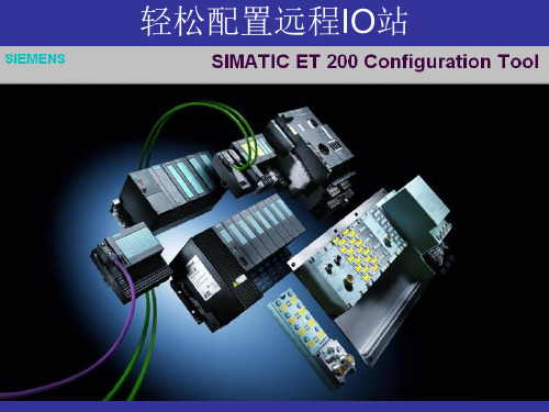
配置HW
首先,选择需要的 首先, 通讯总线 和 CPU 。
配置HW
双击ET200设备或 双击ET200设备或CPU的 设备或CPU的 的通讯接口, 的通讯接口,打开相应的 接口参数对话框Βιβλιοθήκη 接口参数对话框。配置HW
在“Bus Assignment”中, Assignment”中 选择需要的网络, 选择需要的网络,设定工作 模式,设定地址。 模式,设定地址。
In the HW config of STEP7, choose the menu item “Station“ -> “Import…“ and set the path for the cfg file. Select the file configuration to be imported and start the import procedure with ”Open“.
轻松配置远程IO站
ET 200 CFG Tool
• 功能
– 包含项目或从站的管理 – 模块及端子模块的直观配置选择 – 校验检查从站的配置错误 – 检查从站的限制 – 允许专家模式的配置 – 配件 – 电位分配图 – 元件订单(Excel)
ET 200 CFG Tool
• 内容
– ET200iSP – ET200Pro – ET200S – ET200M – ET200eco
导出HW
设置完所有设备和CPU的 设置完所有设备和CPU的 接口后,请点击“ 接口后,请点击“Export HW Configuration”,选择 Configuration”, 保存的路径。 保存的路径。则配置文件 .cfg”可以在 可以在STEP “.cfg”可以在STEP 7
STEP 7 中导入HW
ET 200eco PN操作说明
指南
本手册介绍了 ET 200eco PN 分布式 I/O 设备的硬件。 它包括说明部分和参考部分(规 范)。 本手册中涵盖的主题。 ● ET 200eco PN 分布式 I/O 设备的安装和接线 ● ET 200eco PN 分布式 I/O 设备的调试和诊断 ● ET 200eco PN 分布式 I/O 设备的组件 ● 订货号 ● 词汇表中介绍了一些重要术语。 ● 索引可帮助您迅速找到与关键字相关的所有文本。
2.1
安装位置、安装尺寸 ........................................................................................................... 1................................................................................................................ 15
Siemens AG Industry Sector Postfach 48 48 90026 NÜRNBERG 德国
A5E01250254-01 Ⓟ 01/2009
Copyright © Siemens AG
2008. 本公司保留技术更改的权利
前言
本手册用途
准循本手册中的信息,在 PROFIBUS IO 上将 ET 200eco PN 分布式 I/O 设备用为 IO 设 备。
2 安装 ................................................................................................................................................15
ET 200SP 基座单元 (BaseUnit) 使用入门说明书

下载中心文档编号产品类别下载中心中文标题文档类型发布时间简单描述关键字下载地址A0837/自动化系统/ET200/ET 200SP ET 200SP基座单元(BaseUnit)使用入门操作指南9/17/2013针对ET 200SP基座单元(BaseUint)的选型及使用进行介绍ET 200SP, ET200SP 基座单元/download/docMessage.aspx?Id=7447A0829/通信/网络/PROFINET/PLC F-CPU之间安全相关的控制器-智能设备通信(Portal V11)操作指南9/13/2013通过实例介绍了在S7分布式安全中,在博途V11环境下如何实现IO控制器和智能设备间的安全相关通信。
分布式安全,IO控制器,智能设备,TIA博途/download/docMessage.aspx?Id=7446F1028/驱动技术/运动控制系统SIMOTION/SIMOTION软件/工程软件/Service toolssoftware/PLCengineeringsystem/SIMATICprogrammingsystem/STEP 7SINAMICS G120 CU240B/E-2、CU250S-2如何使用自由功能块实现自动的周期启停常问问题9/12/2013本文介绍SINAMICS G120 CU240B/E-2、CU250S-2如何使用自由功能块实现自动的周期启停/download/docMessage.aspx?Id=7445F1029/驱动技术/低压交流变频器/SINAMICSG120 chassis units 如何修改SINAMICS G120 (<V4.0)强制潜在故障检查时间间隔常问问题9/12/2013本文介绍如何修改CU240S DP(PN)-F强制潜在故障检查时间间隔/download/docMessage.aspx?Id=7442A0836/通信/网络/工业远程通信/modem 基于WCDMA网络在SCALANCES612与SCALANCE M875之间建立VPN操作指南9/12/2013本文主要介绍如何基于WCDMA的无线网络配置SCALANCE S612与SCALANCEM875的VPN,实现对PLC的远程诊断、远程编程、远程维护。
西门子Simatic ET 200SP产品说明书

Input current Current consumption (rated value) Current consumption, max. Inrush current, max. I²t
Power Infeed power to the backplane bus
0 °C 60 °C 0 °C 50 °C 5 000 m; Restrictions for installation altitudes > 2 000 m, see manual
Yes; + 16 ET 200AL modules
50 mm 117 mm 74 mm
190 g; IM 155-6 PN BA with 2x RJ45 ports and server module 05/13/2020
Power loss Power loss, typ.
Address area Address space per module ● Address space per module, max. Address space per station ● Address space per station, max.
IM 155-6 PN ST FS01 V4.1
Yes; I&M0 to I&M3 Yes; Single hot swapping
No
V14
V5.5 SP4 and higher V2.3 / -
Configuration control
via dataset
Yes
Supply voltage
Rated value (DC)
ET200-组态工具(CN)

STEP 7 中导入HW
Create a new project in STEP7, select the same CPU type as in the network configuration of the ET200 configurator and open the hardware.
在STEP 7 中创建一个新的 工程,按照选择CPU站的 类型,
轻松配置远程IO站
ET 200 CFG Tool
• 功能
– 包含项目或从站的管理 – 模块及端子模块的直观配置选择 – 校验检查从站的配置错误 – 检查从站的限制 – 允许专家模式的配置 – 配件 – 电位分配图 – 元件订单(Excel)
ET 200 CFG Tool
• 内容
– ET200iSP – ET200Pro – ET200S – ET200M – ET200eco
In the HW config of STEP7, choose the menu item “Station“ -> “Import…“ and set the path for the cfg file. Select the file configuration to be imported and start the import procedure with ”Open“.
系统图
开始导出HW
在现场总线设备创建完毕、 检查完毕后,就可以进行 HW导出 选择需要导出的设备,在 点击”Export to HW config.“ 按钮。 “ET200 configurator network configuration“ 窗口打开。
配置HW
首先,选择需要的 通讯总线 和 CPU 。
PLC-300ET200M组态
本栏论题:PROFIBUS-DP连接ET200M的实例:主站S7-400连接ET200M [14823]
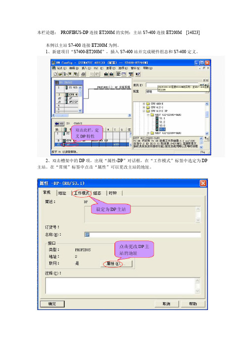
本例以主站S7-400连接ET200M为例。
1、新建项目“S7400-ET200M”,插入S7-400站并完成硬件组态和S7-400定义。
2、双击槽架中的DP项,出现“属性-DP”对话框,在“工作模式”标签中选定为DP 主站。
在“常规”标签中点击“属性”可以更改主站的地址。
3、在组态好的DP系统中挂上ET200M从站,同时会弹出“属性-PROFIBUS”对话框,此时可点“取消”过后再设置ET200M的属性。
4、双击组态好的ET200M图标,出现“DP从站属性”对话框。
5、点击上图“常规”标签中“节点/主站系统”中的PROFIBUS项,出现“属性-PROFIBUS接口”对话框,在其“参数”标签中设定ET200M的地址(注意设定地址须和ET200M硬件上拨码数字相同,且不能和其它站冲突)。
6、组态ET200M的硬件I/O。
这时可以根据需要从IM153-1栏下进行硬件组态,如:AI是模拟量输入,DI/DO是开关量输入输出等。
7、ET200M硬件组态好后如图所示(16点DI/16点DO),其输入地址是IW0,输出地址是QW0。
ET200M分站的组态

PROFIBUS-DP连接ET200M的实例
以主站S7-400连接ET200M为例。
1、新建项目“S7400-ET200M”,插入S7-400站并完成硬件组态和S7-400定义。
双击此栏,定
义DP特性
2、双击槽架中的DP项,出现“属性-DP”对话框,在“工作模式”标签中选定为DP主站。
在“常规”标签中点击“属性”可以更改主站的地址。
3、在组态好的DP 系统中挂上ET200M 从站,同时会弹出“属性-PROFIBUS ”对话框,此时可点“取消”过后再设置ET200M 的属性。
4、双击组态好的ET200M 图标,出现“DP 从站属性”对话框。
点击更改DP 主
站的地址
设定为DP 主站
按住此处不放拖动
到DP 图标上即可把
ET200M 挂于系统中
DP 图标 组态好后的
ET200M
点击此处设置
ET200M的地址。
5、点击上图“常规”标签中“节点/主站系统”中的PROFIBUS项,出现“属性-PROFIBUS接口”对话框,在其“参数”标签中设定ET200M的地址(注意设定地址须和ET200M硬件上拨码数字相同,且不能和其它站冲突)。
6、组态ET200M的硬件I/O。
这时可以根据需要从IM153-1栏下进行硬件组态,如:AI是模拟量输入,DI/DO是开关量输入输出等。
7、ET200M硬件组态好后如图所示(16点DI/16点DO),其输入地址是IW0,输出地址是QW0。
SIMATIC ET 200S 4POTDIS模块说明书

SIMATICET 200S distributed I/O 4POTDIS module(6ES7138-4FD00-0AA0) Manual04/2007A5E01077612-01Safety GuidelinesThis manual contains notices you have to observe in order to ensure your personal safety, as well as to preventdamage to property. The notices referring to your personal safety are highlighted in the manual by a safety alertsymbol, notices referring only to property damage have no safety alert symbol. These notices shown below aregraded according to the degree of danger.DANGERindicates that death or severe personal injury will result if proper precautions are not taken.WARNINGindicates that death or severe personal injury may result if proper precautions are not taken.CAUTIONwith a safety alert symbol, indicates that minor personal injury can result if proper precautions are not taken.CAUTIONwithout a safety alert symbol, indicates that property damage can result if proper precautions are not taken.NOTICEindicates that an unintended result or situation can occur if the corresponding information is not taken intoaccount.If more than one degree of danger is present, the warning notice representing the highest degree of danger willbe used. A notice warning of injury to persons with a safety alert symbol may also include a warning relating toproperty damage.Qualified PersonnelThe device/system may only be set up and used in conjunction with this documentation. Commissioning andoperation of a device/system may only be performed by qualified personnel. Within the context of the safety notesin this documentation qualified persons are defined as persons who are authorized to commission, ground andlabel devices, systems and circuits in accordance with established safety practices and standards.Prescribed UsageNote the following:WARNINGThis device may only be used for the applications described in the catalog or the technical description and onlyin connection with devices or components from other manufacturers which have been approved orrecommended by Siemens. Correct, reliable operation of the product requires proper transport, storage,positioning and assembly as well as careful operation and maintenance.TrademarksAll names identified by ® are registered trademarks of the Siemens AG. The remaining trademarks in thispublication may be trademarks whose use by third parties for their own purposes could violate the rights of theowner.Disclaimer of LiabilityWe have reviewed the contents of this publication to ensure consistency with the hardware and softwaredescribed. Since variance cannot be precluded entirely, we cannot guarantee full consistency. However, theinformation in this publication is reviewed regularly and any necessary corrections are included in subsequenteditions.Siemens AG Automation and Drives Postfach 48 48 90327 NÜRNBERG GERMANY Ordernumber: A5E01077612-01Ⓟ 09/2007Copyright © Siemens AG 2007.Technical data subject to change4POTDIS module (6ES7138-4FD00-0AA0) Manual, 04/2007, A5E01077612-013PrefacePurpose of the manualThis manual supplements the ET 200S Distributed I/O System Operating Instructions. General functions for the ET 200S are described in the ET 200S Distributed I/O System Operating Instructions.The information in this document along with the operating instructions enables you to commission the ET 200S.Basic knowledge requirementsTo understand these operating instructions you should have general knowledge of automation engineering.Scope of the manualThis manual applies to this ET 200S module. It describes the components that are valid at the time of publication.Recycling and disposalThanks to the fact that it is low in contaminants, this ET 200S module is recyclable. For environmentally compliant recycling and disposal of your electronic waste, please contact a company certified for the disposal of electronic waste.Additional supportIf you have any questions relating to the products described in these operating instructions, and do not find the answers in this document, please contact your local Siemens representative./automation/partnerThe portal to our technical documentation for the various SIMATIC products and systems is available at:/automation/simatic/portal The online catalog and ordering system are available at: /automation/mallPreface4POTDIS module (6ES7138-4FD00-0AA0)4Manual, 04/2007, A5E01077612-01Training centerWe offer courses to help you get started with the ET 200S and the SIMATIC S7 automation system. Please contact your regional training center or the central training center in D -90327, Nuremberg, Germany. Phone: +49 (911) 895-3200. /sitrainTechnical SupportYou can reach technical support for all A&D projects ● using the support request web form:/automation/support-request ● Phone: + 49 180 5050 222 ● Fax: + 49 180 5050 223For more information about our technical support, refer to our Web site at http://www.siemens.de/automation/serviceService & Support on the InternetIn addition to our documentation services, you can also make use of our comprehensive online knowledge base on the Internet./automation/service&support There you will find:● Our Newsletter, which constantly provides you with the latest information about your products. ● The right documentation for you using our Service & Support search engine. ● The bulletin board, a worldwide knowledge exchange for users and experts. ● Your local contact for Automation & Drives in our contact database.● Information about on-site services, repairs, spare parts. Lots more can be found on our "Services" pages.Table of contentsPreface (3)1 4POTDIS module (6ES7138-4FD00-0AA0) (7)1.1 Potential distributor module 4POTDIS (6ES7138-4FD00-0AA0) (77)Index (11)4POTDIS module (6ES7138-4FD00-0AA0)Manual, 04/2007, A5E01077612-01 5Table of contents4POTDIS module (6ES7138-4FD00-0AA0) 6Manual, 04/2007, A5E01077612-014POTDIS module (6ES7138-4FD00-0AA0) Manual, 04/2007, A5E01077612-0174POTDIS module (6ES7138-4FD00-0AA0)11.1Potential distributor module 4POTDIS (6ES7138-4FD00-0AA0)Properties● Potential distributor module with 4 outputs ● Output current 5A per output / 10A per module● Rated load voltage: In accordance with the load voltage at the power module of this load voltage groupGeneral terminal assignmentNoteTerminals 4, 8, A4, A8, A3 and A7 are only available at specified terminal modules.Terminal assignment for 4POTDIS (6ES7138-4FD00-0AA0)Terminal Assignment Terminal Assignment Notes1 L 5 L2 L 6 L3 M 7 M4 M 8 M A4 AUX1 A8 AUX1 A3AUX1A7AUX1• L: Load voltage in accordance with Terminals 2, 6 of the PM-E • M: Potential in accordance with Terminals 3, 7 of the PM-E• AUX1: Protective-conductor terminal or potential bus (freely usableup to 230 V AC)1.1 Potential distributor module 4POTDIS (6ES7138-4FD00-0AA0)4POTDIS module (6ES7138-4FD00-0AA0)8Manual, 04/2007, A5E01077612-01Usable terminal modulesBlock diagramFigure 1-1 Block diagram of the 4POTDIS1.1 Potential distributor module 4POTDIS (6ES7138-4FD00-0AA0)4POTDIS module (6ES7138-4FD00-0AA0) Manual, 04/2007, A5E01077612-019Technical specificationsDimensions and weightDimensions W × H × D (mm)(the total dimensions depend on the selected terminal module) 15 × 81 × 52WeightApprox. 33gModule-specific dataSupports isochronous operation No Number of outputs 4 Cable length• Unshielded Max. 600m • Shielded Max. 1000 m Parameter length1 byteVoltages, currents, potentialsRated load voltage L+ (from the power module) 24 to 48 VDC 24 to 230 VAC • Reverse polarity protectionNo Total current of the outputs (per module) Max. 10 A Electrical isolation • Between the channelsNo • Between the channels and backplane bus Yes Permissible potential difference• Between the supply voltage and backplanebus 75 VDC, 240 VAC Insulation testedYes• Between the supply voltage and backplanebus 500 VDC, 1500 VAC Diagnostic interruptNoData for selecting an actuatorShort-circuit protection of the outputNo, possible via PM-E or externallyNoteIf further modules are positioned between the power module PM-E and the potentialdistributor module 4POTDIS, the total current is reduced by the value of the currents of the individual modules.1.1 Potential distributor module 4POTDIS (6ES7138-4FD00-0AA0)4POTDIS module (6ES7138-4FD00-0AA0) 10Manual, 04/2007, A5E01077612-014POTDIS module (6ES7138-4FD00-0AA0) Manual, 04/2007, A5E01077612-01 11IndexB Basic knowledge requirements, 3 D Disposal, 3 I Internet Service & Support, 4 R Recycling, 3 S Scope Manual, 3 Service & Support, 4 T Technical Support, 4 Training center, 4Index4POTDIS module (6ES7138-4FD00-0AA0) 12Manual, 04/2007, A5E01077612-01。
西门子冗余组态及ET200SP组态注意事项202009
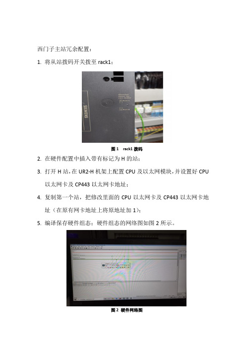
西门子主站冗余配置:1.将从站拨码开关拨至rack1;图1 rack1拨码2.在硬件配置中插入带有标记为H的站;3.打开H站,在UR2-H机架上配置CPU及以太网模块,并设置好CPU以太网卡及CP443以太网卡地址;4.复制第一个站,把修改里面的CPU以太网卡及CP443以太网卡地址(在原有网卡地址上将原地址加1);5.编译保存硬件组态;硬件组态的网络图如图2所示。
图2 硬件网络图6.插入OB块,如OB72,OB73,OB80~OB88等;7.给CPU上电,并将硬件组态及软件块下载到主CPU中。
8.成功后的组态状态如图3所示。
图3 冗余配置成功图ET200SP主站配置:1.选择合适的基座,一共有两种基座,一种为白色有源(尾号为D的基座配电模块),一种为黑色(尾号为B的基座模块),第一个肯定是白色的;软件里面需要根据不同的底座类型选择是否是配电模块。
2.空槽需要配置(BU-cover 15mm),最后还有一个截止模块(servermodule V1.1);如图4所示;图4 空槽及截止模块图3.ET200SP通讯模块的地址需要配置(ET200SP的MAC地址都是随设备出厂固化到里面的,配置的时候需要记下MAC地址),用菜单PLC-编辑Ethernet节点界面找到MAC地址再配置相应IP地址,之前PG/PC接口的选取,必须用TCP/IP;图5 IP地址配置4.IP地址配置好后,需要在给ET200SP站分配一个ID名字,如WT01,WT02等;5.需要在配电模块属性里面将配电模块使能参数设置一下;如图6所示。
图6 配电模块属性配置6.配置成功后,LK1和LK2指示网线会有联通指示灯。
注意TC块与RTD块的区别,RTD模块配置好后不会闪灯,但TC块会闪,两者硬件相同,但里面的设置不同。
7.注意冗余PLC之间是通过光纤跳线连接的,中间不能有网线,否则中间机架掉电后其余的机架会出问题。
西门子 ET 200SP HA HART 应用指南说明书

/CN/view/zh/109762437C o p y r i g h t S i e m e n s A G C o p y r i g h t y e a r A l l r i g h t s r e s e r v e d目录1 HART 功能概述 ............................................................................................ 3 2硬件组态及基本设置...................................................................................... 4 2.1 硬件组态及设置 .............................................................................. 4 2.2 通过通道驱动块读取通道模拟量信号 ................................................ 8 2.3 8 HART 设置下的HART 变量 .......................................................... 9 2.4 1 multiHART 或4 multiHART 设置下的HART 变量.......................... 10 2.4.1 1 multiHART................................................................................. 10 2.4.2 4 multiHART (12)3通过读取数据记录访问HART 变量............................................................... 14 3.1 命令3读取HART 变量.................................................................. 14 3.2 命令121读取HART 变量 .. (18)C o p y r i g h t S i e m e n s A G C o p y r i g h t y e a r A l l r i g h t s r e s e r v e d1 HART 功能概述HART 通信是在4-20mA 信号上叠加一个幅值为±0.5mA 的正弦波信号,通过调整正弦波的频率来表示信号0和1,如图1-1所示,1200Hz 表示1,2200Hz 表示0。
ET200组态工具手册

ET200配置工具CA01产品目录/download/Info/00001/ET200分布式I/O系统硬件配置分布式I/O系统订货清单Æ使用使用使用Step1:选择槽号Step2:选择信号或接口模块Step3:选择链接模块Step4:确定使用选择该命令检查配置的正确性使用正确的站点配置对昂贵的常规安全电缆布线的要求降低!使用使用使用使用Step1:选择Step2:选择Step3:选择Step4:确定使用按照同样的方法配置ET200Pro、ET200S、ET200Isp,最后的网络如下所示:使用选择Export to HW-Config选择保存文件的位置和文件名称使用Step1: 选择项目Step2: 选择Parts ListStep3: 选择ConfigurationÆExport Parts List,导出配置清单使用使用一个ET200Eco站点分布式I/O系统硬件配置分布式I/O系统订货清单配置工具可以配置ET200M、ET200is、ET200L,内置的ET200配置工具也可ET200Pro站点,但不能加入到控制系统中。
选择“商品”,出现右图画面Step1:选择“选择辅助程序”菜单Step2:选择“SIMATIC”菜单ÆStep1: 选择“Distributed I/O”Step2: 选择“Determine network”Step3: 选择“Load selection”,系统画面如下:Step5: “选择”Accept”,画面如下所示Step4: 输入总线名称,如”Profibus DP”完成总线配置后的显示Step1: 选择“Item Selection”,系统画面如下所示Step3: 选择“ET200M”Step2: 选择“Distributed I/O System”Step4: 选择“Accept”Step6: 选择“Accept”Step5: 修改ET200M名称,如ET200M完成插入ET200M站点后的显示Step1: 双击“ET200M”,进入ET200M配置站点,出现如下画面Step2: 选择ET200M站点的接口模块,点击左侧的”+“号,出现如下的画面Step3:找到需要的接口模块型号,同时可以为该模块选择附件,如DP接头所选模块的简要说明内容Step4:点击此按钮将接口模块加入到配置清单中Step5:在此处输入同类型模块数量为了能够在Profibus DP网络中出现该站点,点击此按钮,系统出现如下的画面点击此按钮回到配置主画面Step1: 选择“Item Selection”,系统画面如下所示Step2: 选择“Automation systems Simatic S7”Step3: 选择“Simatic S7-400”Step4: 选择统出现如下的画面Step6: 选择“Accept”,系统出现如下画面Step5:修改系统的名称,如S7-414Step7: 双击“S7-414”后出现如下的画面Step8: 选择“Racks and Interfacemodules”前的“+”号,展开后选择“UR2,Central Controller”Step9:添加到订货清单中Step10:输入相同模块的数量为了能够在Profibus DP网络上出现该站点,点击此按钮,系统出现如下的画面点击此按钮回到配置主画面点击该按钮进入Profibus DP网络配置图,如下图所示Step1:双击该位置后,出现如下的画面Step2:选择“Profibus DP”网络Step3:选择Master or SlaveStep4:选择DP站地址Step5:选择“Load”,完成点击此按钮回到配置主画面最后选择。
ET200
3.5.5 组态紧凑型DP 从站步骤1. 从“硬件目录”窗口中选择一个紧凑型DP 从站(例如,ET 200B)。
2. 将该DP 从站拖到后面代表DP 主站系统的符号上:“属性- PROFIBUS 节点”对话框打开。
在此,可进行下列设置:- PROFIBUS 子网的属性(传输率等)- DP 从站的PROFIBUS 地址。
3. 点击“确定”,确认设置。
结果:一个代表紧凑型DP 从站的符号连接到DP 主站系统。
在站窗口的下半部分显示紧凑型DP 从站的I/O 组态(详细视图)。
3.5.6 组态模块化DP 从站步骤1. 从“硬件目录”窗口中为模块化DP 从站选择一个接口模块(例如,为ET 200M 选择IM 153)。
2. 将接口模块拖到后面代表DP 主站系统的符号上:结果:“属性- PROFIBUS 节点”对话框打开。
在此,可进行下列设置:- PROFIBUS 子网的属性(传输率等)。
- DP 从站的PROFIBUS 地址。
3. 点击“确定”,确认设置。
DP 从站的符号连接到DP 主站系统。
在站窗口的下半部分显示DP 从站的详细视图,其中显示所有可能的插槽或DP 标识符。
4. 在站窗口的下半部分为模块化DP 从站分配模块。
对于模块化DP 从站,可能用到的模块都位于“硬件目录”窗口中相关的DP 从站“系列”下。
例如,有以下一些模块:- 用于智能连接(ET 200L SC 系列)的接线板(TB...SC)- SC 子模块(ET 200L SC 系列)- AS-i 从站(DP/AS-i Link 系列)- S7-300 模块(ET 200M 系列)组态分布式I/O(DP)组态硬件和通讯连接,STEP 7 V5.3 版本A5E00446503-01 3-153.5.7 将DP 从站分配到SYNC 或FREEZE 组中具有合适功能的DP 主站可以同时发送SYNC 和/或FREEZE 控制命令到一组从站中,来同步DP 从站。
ET 200SP SIMATIC ET 200SP 设备手册说明书
SIMATICET 200SP设备手册 RQ3x120VDC-230VAC/5A CO n.i. ST (6ES7132-6HC70-0BU0)设备手册Siemens AG Digital Industries Postfach 48 4890026 NÜRNBERG A5E50097132-AAⓅ 05/2020 本公司保留更改的权利Copyright © Siemens AG 2020. 保留所有权利法律资讯警告提示系统为了您的人身安全以及避免财产损失,必须注意本手册中的提示。
人身安全的提示用一个警告三角表示,仅与财产损失有关的提示不带警告三角。
警告提示根据危险等级由高到低如下表示。
危险表示如果不采取相应的小心措施,将会导致死亡或者严重的人身伤害。
警告表示如果不采取相应的小心措施,可能导致死亡或者严重的人身伤害。
小心表示如果不采取相应的小心措施,可能导致轻微的人身伤害。
注意表示如果不采取相应的小心措施,可能导致财产损失。
当出现多个危险等级的情况下,每次总是使用最高等级的警告提示。
如果在某个警告提示中带有警告可能导致人身伤害的警告三角,则可能在该警告提示中另外还附带有可能导致财产损失的警告。
合格的专业人员本文件所属的产品/系统只允许由符合各项工作要求的合格人员进行操作。
其操作必须遵照各自附带的文件说明,特别是其中的安全及警告提示。
由于具备相关培训及经验,合格人员可以察觉本产品/系统的风险,并避免可能的危险。
按规定使用 Siemens 产品请注意下列说明:警告Siemens 产品只允许用于目录和相关技术文件中规定的使用情况。
如果要使用其他公司的产品和组件,必须得到 Siemens 推荐和允许。
正确的运输、储存、组装、装配、安装、调试、操作和维护是产品安全、正常运行的前提。
必须保证允许的环境条件。
必须注意相关文件中的提示。
商标所有带有标记符号 ® 的都是 Siemens AG 的注册商标。
Siemens SIMATIC ET 200SP BaseUnit 数据手册说明书

-30 °C 60 °C -30 °C 50 °C
2 000 m; On request: Installation altitudes greater than 2 000 m
Push-in terminal 0.14 mm²; 0.2 mm² without wire end ferrule 2.5 mm²; 1.5 mm² with wire end ferrule 16 0 0 2
07/13/2020
Subject to change without notice © Copyright Siemens
No
10 A 10 A
07/13/2020
Subject to change without notice © Copyright Siemens
For AUX bus, max. For process terminals, max.
Hardware configuration Automatic encoding Formation of potential groups ● New potential group ● Potential group continued from the left Slots ● Number of slots
Data sheeATIC ET 200SP, BaseUnit BU20-P16+A0+2D, BU-TYPE U0, Packaging Unit: 1 Pieces, Push-in terminals, w/o AUX-terminals, new potential group, WxH: 20mm x 117mm
General information Product type designation HW functional status
- 1、下载文档前请自行甄别文档内容的完整性,平台不提供额外的编辑、内容补充、找答案等附加服务。
- 2、"仅部分预览"的文档,不可在线预览部分如存在完整性等问题,可反馈申请退款(可完整预览的文档不适用该条件!)。
- 3、如文档侵犯您的权益,请联系客服反馈,我们会尽快为您处理(人工客服工作时间:9:00-18:30)。
ET200配置工具CA01产品目录
/download/Info/00001/ET200
分布式I/O系统硬件配置分布式I/O系统订货清单
Æ
使用
使用
使用
Step1:选择槽号
Step2:选择信号或接口模块
Step3:选择链接模块
Step4:确定
使用
选择该命令检查配置的正确性
使用
正确的站点配置
对昂贵的常规安全电缆布线的要求降低!
使用
使用
使用
使用
Step1:选择
Step2:选择
Step3:选择Step4:确定
使用
按照同样的方法配置ET200Pro、ET200S、ET200Isp,最后的网络如下所示:
使用
选择Export to HW-Config
选择保存文件的位置和文件名称
使用
Step1: 选择项目Step2: 选择Parts List
Step3: 选择ConfigurationÆExport Parts List,导出配置清单
使用
使用
一个ET200Eco站点
分布式I/O系统硬件配置分布式I/O系统订货清单
配置工具可以配置ET200M、ET200is、
ET200L,内置的ET200配置工具也可
ET200Pro站点,但不能加入到控制系统中。
选择“商品”,出现右图画面
Step1:选择“选择辅助程序”菜单Step2:选择“SIMATIC”菜单
Æ
Step1: 选择“Distributed I/O”
Step2: 选择“Determine network”
Step3: 选择“Load selection”,系统画面如下:
Step5: “选择”Accept”,画面如下所示
Step4: 输入总线名
称,如”Profibus DP”
完成总线配置后的显示
Step1: 选择“Item Selection”,系统画面如下所示
Step3: 选择“ET200M”
Step2: 选择“Distributed I/O System”
Step4: 选择“Accept”
Step6: 选择“Accept”
Step5: 修改ET200M名
称,如ET200M
完成插入ET200M站点后的显示
Step1: 双击“ET200M”,进入ET200M配置站点,出现如下画面
Step2: 选择ET200M站点的接口模块,点击左侧的”+“号,出现如下的画面
Step3:找到需要的接口模块型号,
同时可以为该模块选择附件,如DP
接头
所选模块的简要说明内容Step4:点击此按钮将接口模块加入到
配置清单中
Step5:在此处输入同类型模块数量
为了能够在Profibus DP网络中出现该站点,点击此按钮,系统出现如下的画面
点击此按钮回到配置主画面
Step1: 选择“Item Selection”,系统画面如下所示
Step2: 选择“Automation systems Simatic S7”Step3: 选择“Simatic S7-400”
Step4: 选择
统出现如下的画面
Step6: 选择“Accept”,系统
出现如下画面
Step5:修改系统的名
称,如S7-414
Step7: 双击“S7-414”后出现如下的画面
Step8: 选择“Racks and Interface
modules”前的“+”号,展开后选择
“UR2,Central Controller”
Step9:添加到订货清单中Step10:输入相同模块的数量
为了能够在Profibus DP网络上出现该站点,点击此按钮,系统出现如下的画面
点击此按钮回到配置主画面
点击该按钮进入Profibus DP网络配置图,如下图所示
Step1:双击该位置后,出现如下的画面
Step2:选择“Profibus DP”网络
Step3:选择Master or Slave
Step4:选择DP站地址
Step5:选择“Load”,完成
点击此按钮回到配置主画面
最后选择。
