力士乐负载敏感阀讲解ppt-课件
力士乐M4-15操作阀
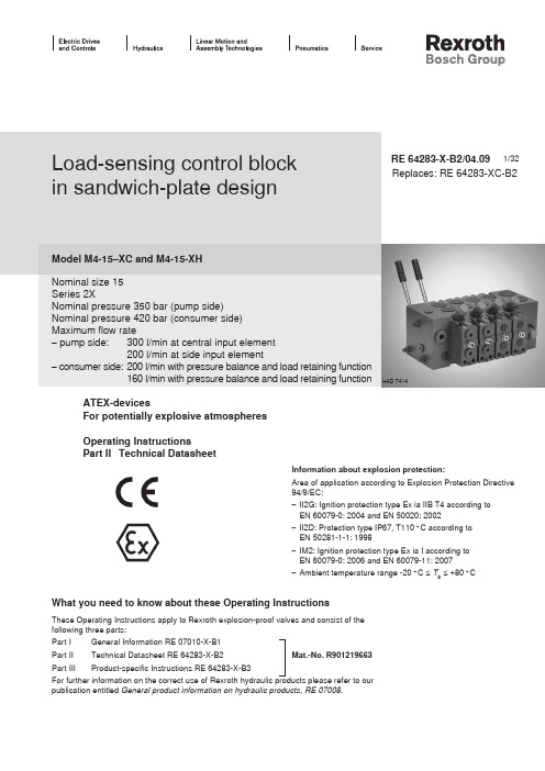
1/32Replaces: RE 64283-XC-B2 Load-sensing control blockin sandwich-plate designModel M4-15–XC and M4-15-XHNominal size 15Series 2XNominal pressure 350 bar (pump side)Nominal pressure 420 bar (consumer side)Maximum flow rate– pump side: 300 l/min at central input element200 l/min at side input element– consumer side: 200 l/min with pressure balance and load retaining function160 l/min with pressure balance and load retaining functionRE 64283-X-B2/04.09HAD 7414ATEX-devicesFor potentially explosive atmospheresOperating InstructionsPart II Technical DatasheetWhat you need to know about these Operating InstructionsThese Operating Instructions apply to Rexroth explosion-proof valves and consist of thefollowing three parts:Part I General Information RE 07010-X-B1Part II Technical Datasheet RE 64283-X-B2 Mat.-No. R901219663Part III Product-specific Instructions RE 64283-X-B3For further information on the correct use of Rexroth hydraulic products please refer to ourpublication entitled General product information on hydraulic products, RE 07008.Information about explosion protection:Area of application according to Explosion Protection Directive94/9/EC:I I2G: Ignition protection type Ex ia IIB T4 according to–EN 60079-0: 2004 and EN 50020: 2002II2D: Protection type IP67, T110 °C according to–EN 50281-1-1: 1998IM2: Ignition protection type Ex ia I according to–EN 60079-0: 2006 and EN 60079-11: 2007Ambient temperature range -20 °C ≤–T a ≤ +80 °CContent PageCharacteristics 3Function, section 4Symbol4Technical data5 to 7Modular construction 8, 9Ordering details10 to 12Ordering examples 13, 14Input elements15 to 17Directional control valve elements18Pressure balance 18LS pressure limitation19Main piston 20Flow rate21Actuation types, cover A 22Actuation types, cover B 23Secondary valves 24End elements 25 to 28Unit dimensions29 to 31Summary of the contentsSystemLoad-pressure independent flow rate control–Open Center for fixed displacement pump• Closed Center for variable displacement pump• ConstructionSandwich-plate design–Input element• up to 9 directional control valve elements, of which • max. 6 with servo controlup to 18 directional control valve elements with central-• input element, of which max. 6 with servo control End element• Actuation types–mechanical (hand lever)• hydraulic• servo-hydraulic• CharacteristicsFlow rateload pressure compensated –high repeating accuracy –low hysteresis –Pressure limitationInput element–pilot-operated pressure valves with large nominal width • Directional control valve element / consumer ports –compact pressure-control valves with supply function • LS pressure limitation–selectable pressure setting per consumer port on request • (design by technical sales)Function, section1 Housing2 Main piston3 4 SymbolConnections:P PumpA, B Consumer T TankX Control oil supply Y Control oil drain LSLoad sensing (LS)M A , M Bexternal LS-portsControl block M4-15The directional control valves are proportional valves in accordance with the load-sensing principle.Consumer activationThe flow direction and the size of the flow rate reaching the consumer ports (A or B) are determined at the main piston (2).External pilot units control the position of the main piston (2). The extent of the control pressure in the spring chambers (8) determines the travel of the main piston (P → A; P → B).The pressure difference at the main piston (2) and therefore also the flow rate to the consumer is kept constant via the pressure balance (3).Load pressure compensationPressure changes at the consumers or the pump arecompensated respectively by the pressure balance (3). The flow rate to the consumer remains constant even under diffe-rent loads.Flow rate limitationThe maximum flow rate can be individually limited from the works to order specifications by means of travel stops (6).Pressure limitationThe manipulation of the LS pressure of each consumer port can take place internally via the LS pressure relief valves (4) or externally via the LS ports M A , M B .Relief valves with large nominal widths with combined supply function (5) protect consumer ports A and B from pressure peaks.The highest load pressure is signalled to the pump via the LS line and the integrated shuttle valves (7).5.1 Secondary valve 5.2 Screw cap7 LS-shuttle valve 8 Spring chamber 10 Hand lever 11 Cover ATechnical data (please ask in case of applications outside the stated values!)GeneralMounting orientation anyType of port Pipe thread according to ISO 228/1Mass Input element, sidekg 7Input element with priority valve kg 10Central input elementkg 8.5Directional control valve element, me-chanicalkg6.9Directional control valve element, hydraulickg 7.1Additional weight hand lever kg 1.5End elementkg 5,8Surface protectionPaintAmbient temperature range ϑ°C –20 to +80mechanical Actuating force at hand leverN < 20hydraulicFlow ratePort P q Vmax l/min 300 with central input element l/min 200 with side input elementPort A, Bq Vmax l/min 160 with pressure balance and load retaining function (model "S")l/min 200 with pressure balance, without load retaining function (model "T")Nominal pressurep nom bar 350Max. operating pressure at portP p bar 350A / B p bar 420LS p bar 330T p bar 30Yp bar depressurized to tank Max. control pressure at port X p bar 35a, bp bar 35Control pressure range hydraulic p bar 8.5 to 22.5required regulating-Δp at control block 1)Model S p bar 18Model T p bar 25Primary pressure limitation p bar max. 370 (set at the works to order specifications), min. 20 bar above the pressure cut-off value of the pumpLS pressure limitationpbar50 to 330 (adjusted at the works to order specifications)The highest relief pressure for the LS pressure relief valves of the valve manifold set at the works must be at least 20 bar lower than the pressure cut-off value of the pumpHydraulic fluidMineral oil (HL, HLP) to DIN 51524, other hydraulic fluids on request, ignition temperature > 190 °C Temperature range of hydraulic fluid ϑ°C –20 to +80Viscosity range hydraulicνmm²/s10 to 380servo-hydraulic νmm²/s 16 to 200 2)maximum permitted contamination level of hydraulic fluid Purity class to ISO 4406 (c)Class 20/18/15, we recommend for this a filter with a minimum retention rate of β10 ≥ 75Information about explosion protectionProtection class in accordance with Directive 94/9/EC IM2II2G II2D max. surface temperature –T4110 °C Explosion protection type valve structural safety XC c (EN 13463-5)fail-safe XH EN 60079-0,EN 60079-11EN 60079-0, EN 50020EN 50281-1-1Note The technical data has been established at a viscosity of ν = 30 mm²/s (HLP46: 50 °C).1) Observe the design information for control oil supply with servo-hydraulic operation on page 14.2) Between 200 and 380 mm²/s reduced maximum quantity.Technical Data STDS 0014-1XElectrical connectionelectricalProtection type in accordance with EN 60529:1991+A1:2000 1)IP 67Signal type Direct current analogue Rated current mA20Resistance per coil (total)Ω135 (270) Inductance (serial connection)H1.71) with correctly installed electrical connectionInformation about explosion protectionType test certificate BVS 08 ATEX E031 Protection class in accordance with Directive 94/9/EC IM2Ignition protection type in accordance with EN 60079-0:2006,EN 60079-11:2007Ex ia IIgnition protection type in accordance with EN 50281-1:1998IP67, T110 °C Ambient temperature range°C–20 ≤ T a ≤ +100 The electrical control system must resultfrom fail-safe circuits with the followingmaximum valuesU max V17.5I max mA150P max mW657The interconnection with other devices must be examinedseparately.If a device has been operated with higher electrical powerit should no longer be used in the potentially explosiveatmosphere.Connection plug, bayonet fitting, 3-pin:Type: 845-11-1325-001, SouriauFor associated plug-in connectors see the Souriau data sheet,series 845.It must be ensured that the servo valve is only operated withthese plug-in connectors.ValveTechnical Data STDS 0015-1XElectrical connection(to be observed for II2G)Plug-in connector (to be observed for II2D)ElectricalProtection type in DIN 40050-9:1993 accordance with EN 60529:1991+A1:2000IP 69K IP 67Signal type Direct current analogue Rated currentmA 20Resistance per coil (total) Ω135 (270)Inductance (serial connection)H 1.7Connection plug (compatible with MS 3102 C14S-2P)4-pinInformation about explosion protection Type test certificatePTB 05 ATEX 2058Protection class in accordance with Directive 94/9/ECII2G, II2D Ignition protection type in accordance with EN 60079-0:2004, EN 50020:2002Ex ia IIB T4Ignition protection type in accordance with EN 50281-1-1:1998IP67, T110 °CAmbient temperature range °C–20 ≤ T a ≤ +100Only certified fail-safe circuits with the following maximum values should be used in II2G electrical supply of the valveU maxV 17,5I max mA 150P maxmW 657Recommended safety barrier 1)Single-channele.g. made by Stahl, type 9001/02-133-150-101 or 9001/02-175-100-1011) only necessary for II2GElectrical control with plus (+) to A and minus (–) to B causes pressure at connection A > pressure at connection B and flow rate from P to A and B to T. The pins C and D on the connection plug are not connected.The plug-in connector must fulfil the requirements of the EN 50281-1-1:1998 standard.Warning sign to be provided by the customer "DO NOT DISCONNECT WHEN LIVE".Modular construction: Control block with side input elementControl blocks from series M4-15 are of modular construction. They can be optimally assembled for the respective application.1. Input elementA: Closed Center "VR" with externalpriority consumerB: Open Center "P"C: Closed Center "J"2. Directional control valve elements2.1 LS pressure limitation2.2 Secondary valves2.3 Actuation of cover, A-sideA: Mechanical actuation "M"B: Hydraulic actuation "H"C: Servo-hydraulic actuation "S"2.4 Actuation of cover, B-sideA: Standard cover "–"B: Mechanical actuation "B2" with hand lever 3. End elementA: With LS relief "LA" and "LZ"B: With LS connection and control oil supply "LAY", "LAK", "LZY" and "LZK"C: With LS connection and control oil supply "LAX" and "LZX"Modular construction: Control block with central input element1. Central input elementA: Closed Center central "JZ"B: Closed Center central "VZ" with priority valve 2. Directional control valve elements2.1 LS pressure limitation2.2 Secondary valves2.3 Actuation of cover, A-sideA: Mechanical actuation "M"B: Hydraulic actuation "H"C: Servo-hydraulic actuation "S"2.4 Actuation of cover, B-sideA: Standard cover "–"B: Mechanical actuation "B2" with hand lever 3. End elementA: Deflection plate with external priority port "LVZ"B: Deflection plate "LU"C: With LS relief "LA" and "LZ"D: With LS connection and control oil supply "LAY", "LAK", "LZY" and "LZK"E: With LS connection and control oil supply "LAX" and "LZX"Ordering detailsType codeInput elementsDirectional control valve elementsOrdering detailsEnd elements Additional information6) For details concerning control oil supply see page 17.7) The block preferably contains FKM, but also NBR seals. Make sure that the seal is suitable for the hydraulic fluid used.8) Always in conjunction with protection class IM2Example of a type code of an M4-15 control block with three directional control valve elements:M4–4567–20/3M4–15JH –V 01XH IM2Control block no.Unit series of production series (2 X)Modification status of the seriesNumber of directional control valve elements InputActuation A-side (predominant actuation)Actuation B-side (predominant actuation)Seal materialThreaded connectionIgnition protection type: fail-safe Protection class: IM2Type codeEntire control blocks are defined according to the type code. The order text is intended for the definition of the technical characteristics and requirements. A type code and a material number are derived from the order text by the Bosch Rexroth sales organisation.Ordering detailsOrdering example for Closed Center with side input elementExample:Triple control block–Variable-displacement pump –q V max = 200 l/minNumber of directional control valves, input elementClosed Center with primary pressure- –relief valve at the side, set to 250 bar Directionalcontrol valveelements1st piston axisWith pressure balance, without load –retaining function With LS pressure relief valve for –consumer port A 180 bar, consumer port B 120 bar Piston symbol J,–flow rate in A and B 100 l/min Actuation: hydraulic–Secondary valve holes closed–2nd piston axis With pressure balance, with load–retaining functionWith LS pressure relief valve for –consumer port A and B 180 bar Piston symbol E,–flow rate in A and B 85 l/min Actuation: hydraulic–Secondary valves: pressure/supply –valves, consumer port A and B 350 bar3rd piston axis With pressure balance, with load–retaining functionWith LS pressure relief valve for –consumer port A 180 bar, consumer port B 120 bar Piston symbol E,–flow rate in A and B 85 l/min Actuation: servo-hydraulic–Actuation with hand lever (up), non-rotating –Secondary valves: pressure/supply –valves, consumer port A and B 350 barEnd element With internal LS relief–With internal control oil supply for servo- –hydraulic operationAdditional information FKM seals –Pipe thread connections–Ignition protection type: fail-safe –Protection class: IM2 –Ordering details:3M4152X J250Ordering example for Closed Center for central input with primary valveExample:Double control block–Variable – displacement pump q V max = 200 l/minNumber of directional control valves, end elementDeflection plate–Directionalcontrol valveelement1st piston axisWith pressure balance, without load –retaining function With LS pressure relief valves, –consumer port A 270 bar, consumer port B 300 barPiston symbol E, flow rate in –A and B 100 l/min Actuation: hydraulic–Secondary valve holes closed–Input element Primary pressure relief valve, set to–350 barWith static priority valve, set to 250 bar –Directionalcontrol valveelement2nd piston axisWith pressure balance, with load –retaining function With LS pressure relief valves, –consumer port A 270 bar, consumer port B 300 barPiston symbol E, flow rate in –A and B 90 l/minActuation: mechanical –Hand lever actuation (up) –Secondary valve holes closed–End element With LS relief, without LS connection–With internal control oil supply–Additional information FKM seals –Pipe thread connections–Ignition protection type: structural safety –Protection class: IM2, e. g. for coal mining–Ordering details:2M4152X LU��������������������������������������Input elementsCharacteristic curves (measured at ν = 41 mm²/s and ϑ = 50 °C)Open Center Circulation pressure P → TPriority valvePressure difference in bar →F l o w r a t e q V s i n l /m i n (p r i o r i t y c o n s u m e r )Flow rate in l/min →C i r c u l a t i o n p r e s s u r e p p i n b a r →Closed Center with primary pressure relief valve Ordering details:Brief descriptionFor variable displacement pumps up to 200 l/min –Pressure in bar behind J… required (3-digit) –Technical data for primary valve to RE 64642, –characteristic curve D5Open Center with primary pressure relief valveOrdering details:Brief descriptionfor fixed displacement pumps up to 200 l/min –Pressure in bar behind P… required (3-digit) –Technical data for primary valve to RE 64642, –characteristic curve D5Input elementsClosed Center, priority consumers internal, subordinate consumers external, with primary pressure-relief valve Ordering details:Brief descriptionFor variable displacement pumps up to 200 l/min –Pressure in bar behind VL… for primary –pressure-relief valve required (3-digit)Pressure in bar behind A… for LS pressure –relief valve for priority valve required (3-digit)Closed Center, priority consumers external, subordinate consumers internal, with primary pressure-relief valve Ordering details:Brief descriptionFor variable displacement pumps up to 200 l/min –Pressure in bar behind VR… for primary –pressure-relief valve required (3-digit)Pressure in bar behind A… for LS pressure –relief valve for priority valve required (3-digit)�1; 2) see page 17Closed Center, withprimary pressure relief valveOrdering details:Brief descriptionFor variable displacement pumps up to 300 l/min –Pressure in bar behind JZ… for primary –pressure-relief valve required (3-digit)Technical data for primary valve to RE 64642, –characteristic curve D5Closed Center with priority valve, with primary pressure relief valveOrdering details:Brief descriptionFor variable displacement pumps up to 200 l/min –Pressure in bar behind VR… for primary –pressure-relief valve required (3-digit)Pressure in bar behind A… for LS pressure –relief valve for priority valve required (3-digit)Design information for control oil supply with servo-hydraulic operationIf a servo-hydraulic actuation is used in the control block, please observe the following:External control oil supply:p –st = 30 +2 bar constantq –st = 2 l/min per servo-hydraulic piston axis Imperative for input element P –Internal control oil supply:Maximum 6 servo-hydraulically controlled piston axes possible –No control oil supply for external consumers –Δp on the input element must be at least 35 bar–Input elements1) Version "V … A" is recommended for priority consumerswith a fixed flow rate.2) Version "V … B" is recommended for dynamic priorityconsumers (e.g. steering).Pressure balance piston variants1) The load retaining function is not leakage oil free.����������������������������������Directional control valve elements: LS pressure limitationCharacteristic curvesReduction of consumer flow rate by LS pressure limitationMinimum setting value:50 bar Maximum setting value:330 barSetting value (example)LS pressure in bar →F l o w r a t e i n % →With LS pressure-relief valve and LS screw capBrief descriptionPressure in bar for consumer port A –(3-digit)Screw cap for consumer port B–The LS pressure limitation on the directional –control valve element can be retrofitted for the "QMQ" model.The LS pressure can be externally influenced via –ports M A and M B . These ports can also be used as test ports.Without LS pressure-relief valvesBrief descriptionLS-DB cannot be retrofitted –Housing without test ports–���������������������������������������������������������Directional control valve elements: Main pistonhydraulic actuation servo-hydraulic actuation at 32 mm 2/sT y p i c a l f l o w r a t e i n l /m i n →Piston characteristic curves (symmetrical pistons)P → A/BControl pressure in bar →N o m i n a l f l o w r a t e →Current in mA →Directional control valve elements: Flow rateSymmetrical pistons Piston type Pressure balance Flow rate in l/min (for piston characteristic curve see page 20)E, J, QS 160-160150-150120-120080-080050-050032-032023–023140-140130-130100-100070-070045-045028-028020–020 (8)120-120110-110085-085060-060040-040025-025017–017T200-200190-190160-160100-100065-065040-040Example:Piston type J–Pressure balance S–Reference value: Q –Consumer = 140 l/min Solution:→ 130 litre piston + 2 modules = 150 l/min → Set 140 litre via stroke limiter.Position directional control valve elements with maximum flow rate as close as possible to the input element.Asymmetrical pistons Piston type Pressure balance Flow rate in l/minE, J, QS 150-120120-080080-050050-032130-100100-070070-045045-028110-085085-060060-040040-025T190-160160-100100-065065-040����Directional control valve elements: Actuation types cover A-sidemechanicalOrdering details:Brief descriptionMechanical actuation of main piston. If not–actuated, centering in center position by means of springsAll options for hand lever positions are possible –(K, L, M etc.), also see type code on page 111) –Rotating hand lever 2) –Non-rotating hand leverhydraulicBrief descriptionHydraulic actuation of main piston.–If not actuated, centering in center position by means of springsServo-hydraulicBrief descriptionVoltage:min. 7 VDC–Current type:direct current –Rated current: – ± 20 mA Max. current: –± 25 mADither signal (recommended): –Frequency f: 100 Hz +10 %• Amplitude I • ss :5 mASTDS 0014; see RE 29617-B2 –STDS 0015; see RE 29616-B2 –STDS 0016; see RE 29618-B2–Design by technical sales.Observe the design information for control oil supply with servo-hydraulic operation on page 17.Directional control valve elements: Actuation types cover B-sideMechanical actuation with hand levertop, 60°top, 30°straight, 0°bottom, -30°bottom, -60°Clampingpiece withlever– rotating BBB123B1B1B1123FFF123D1D1D1123DDD123– non-rotating GGG123G1G1G1123HHH123J1J1J1123JJJ123 Clampingpiecewithout lever– rotating T T1U V1V– non-rotating Q Q1S C1CActuating force (on hand lever):mechanical < 20 N–hydraulic, hand lever overlaid < 50 N–Further hand lever options (aluminium-free) on request.Clamping piece with lever(Example: Lever connection in pos. 2)Lever connection on clamping piece����������������������������������������������������������������Directional control valve elements: Secondary valvesPressure/supply valves, adjustableOrdering details:Brief descriptionAdjustable pressure/supply valve, pilot operated –Pressure in bar behind H … required –(3-digit)Example: QH200–Q: Screw cap for consumer side AH200: pressure/supply valve, set to 200 bar for consumer port BTechnical Data to RE 64642–Supply valvesBrief descriptionTechnical Data to RE 64642–P r e s s u r e d i f f e r e n c e i n b a r →Flow rate in l/min →Pressure functionFlow rate in l/min →S e t t i n g p r e s s u r e i n b a r →Supply function����������������End elementsEnd element with LS reliefOrdering details:End element with LS relief and additional P and T portOrdering details:End element with LS relief and internal control oil supplyOrdering details:Brief descriptiondraws oil from the P line, pressure reduced to 35 bar – (firmly set), pressure relief valve set to 45 bar1) The plug is changed if an input element withVR… or VZ… priority is used.End element with LS relief, control oil supply and additional P and T portOrdering details:Brief descriptiondraws oil from the P line, pressure reduced to 35 ba –r (firmly set), pressure relief valve set to 45 bar�������������������������������������������������End elementsEnd element without LS relief Brief descriptionSupply of LS signals connected in parallel –LS relief must be ensured externally–End element without LS relief and additionalP and T port Ordering details:Brief descriptionSupply of LS signals connected in parallel –LS relief must be ensured externally–End element with LS relief and control oil supply Ordering details:Brief descriptionExternal control oil supply necessary – p st max = 33 +2 bar constantEnd element with LS relief, control oilsupply and additional P and T port Brief descriptionExternal control oil supply necessary – p st max = 33 +2 bar constantEnd element with LS relief and internal control oil supply with servo-hydraulic operation Brief descriptionDraws oil from the P line, pressure reduced to –33 +2 bar (firmly set), pressure relief valve set to 45 bar1) The plug is changed if an input element withVR… or VZ… priority is used.Observe the design information for control oil supply with servo-hydraulic operation on page 17.���1) The plug is changed if an input element withVR… or VZ… priority is used.End element without LS relief, with internal control oil supplyDraws oil from the P line, pressure reduced to –35 bar (firmly set), pressure relief valve set to 45 bar Supply of LS signals connected in parallel –LS relief must be ensured externally–End element without LS relief and internalcontrol oil supply with servo-hydraulic operationOrdering details:Brief descriptionDraws oil from the P line, pressure reduced to –33 +2 bar (firmly set), pressure relief valve set to 45 barSupply of LS signals connected in parallel –LS relief must be ensured externally–Observe the design information for control oil supply with servo-hydraulic operation on page 17.End elementsEnd element without LS relief, internalcontrol oil supply and additional P and T portDraws oil from the P line, pressure reduced to–35 bar (firmly set), pressure relief valve set to 45 bar Supply of LS signals connected in parallel –LS relief must be ensured externally–����������������������������������������End element for central input element,deflection plate Ordering details:End elements for combination with central input elementEnd element for central input element, deflection plate with additional T port End element for central input element, deflection plate and additional P and T portBrief descriptionPressure in bar required (3-digit)–End element with external priority portBrief descriptionFor the connection of external –priority consumersEnd element without LS relief, withcontrol oil supply Brief descriptionSupply of LS signals connected in parallel –External control oil supply necessary – p st max = 35 barEnd element without LS relief, with control oil supply and additional P and T port Ordering details:Brief descriptionSupply of LS signals connected in parallel –External control oil supply necessary – p st max = 35 bar End elements。
负载敏感
负载敏感一、负载敏感和压力补偿概念(一)负载敏感(Load Sensing)和压力补偿(Pressure Compensation)是60年代提出的液压传动和控制的新概念。
以往液压系统在使用操纵过程中,存在着以下需解决的问题:1. 节能要求,适应负载变化提供负载所需要的液压功率(流量和压力),尽量减少流量和压力损失,将节流调速改变为以容积调速为主,特别按负载需要提供负载所需的流量。
2. 操纵阀调速控制时,调速受负载压力变化和油泵流量变化的影响,难以操纵控制。
3. 单泵供多执行器:当多执行器同时动作时,要求相互不干涉,能够操纵各执行器按所需流量供油。
合理地分配流量,实现理想复合动作。
4. 液压泵和原动机的匹配问题,能充分利用原动机的功率,保持在发动机最大功率点工作,同时能防止发动机熄火,为了减少能耗节能,要求液压泵和发动机在联合工作最经济点上工作。
为了解决以上问题,60年代提出液压传动控制新概念—负载敏感和压力补偿。
目前液压传动仍存在问题有待解决。
例如液压传动遵循帕斯卡原理,一个泵供多个执行器时,系统压力由克服各负载中所需最大压力来确定,因此供给负载较低的执行器时必然存在压力损失。
目前人们正在研究采用电路中变压器这类东西,来解决这个问题。
(二)负载敏感和压力补偿的定义:负载敏感是一个系统概念,因此应称为负载敏感系统,可把它看作是一个意义广泛的名词。
(即广义的负载敏感和压力补偿)。
负载敏感通过感应检测出负载压力,流量和功率变化信号,向液压系统进行回馈,实现节能控制、流量和调速控制、恒力矩控制、力矩限制、恒功率控制、功率限制、转速限制、同时动作和与原动机动力匹配等控制的总称。
负载敏感系统所采用的控制方式包括液压控制和电子控制。
从负载敏感系统的液压组件来看可分:负载敏感阀:将压力、流量和功率变化信号,向阀进行回馈,实现控制功能的阀。
负载敏感泵:将压力、流量和功率变化信号,向泵进行回馈,实现控制功能的泵和马达。
力士乐闭中心负载敏感压力补偿挖掘机液压系统
力士乐闭中心负载敏感压力补偿挖掘机液压系统主要内容介绍了力士乐闭中心负载敏感压力补偿挖掘机液压系统组成及其工作原理、特性。
重点分析了多路阀液压系统、液压泵控制系统、各主要液压作用元件液压回路及多路阀先导操纵系统等。
目前液压挖掘机有两种油路: 开中心直通回油六通阀系统和闭中心负载敏感压力补偿系统, 我国国产液压挖掘机大多采用”开中心”系统, 而国外著名的挖掘机厂家基本上都采用”闭中心”系统。
闭中心具有明显的优点, 但价格较贵。
国内厂家对开中心系统比较熟悉, 而对闭中心系统不太了解,因此有必要来介绍一下闭中心系统, 本文重点分析力士乐闭中心负载敏感压力补偿(LUDV) 挖掘机油路。
LUDV 意为与负载无关的分配阀。
LUDV系统力士乐挖掘机液压系统可以看作由以下4 部分组成:①多路阀液压系统(主油路) ;②液压泵控制液压系统(包括与发动机综合控制) ;③各液压作用元件液压子系统, 包括动臂、斗杆、铲斗、回转和行走液压系统, 还包括附属装置液压系统;④多路阀操纵和控制液压系统。
LUDV系统是力士乐等公司在改进负荷传感技术的基础上发展起来的,它是不受负载影响的流量分配系统,它将常开式压力补偿改为常闭式,泵所提供的流量与负载所需相匹配,避免了不必要的空流和节流损失。
即使泵的流量小于系统复合动作所需的流量,各动作的相对速度也不会发生变化,从而保证动作的协调性,避免动作冲击。
1 多路阀液压系统多路阀液压系统是液压挖掘机的主油路, 它确定了液压泵如何向各液压作用元件的供油方式, 决定了液压挖掘机的工作特性。
力士乐采用的闭中位负载敏感压力补偿多路阀液压系统的工作原理见图1 (因换向阀不影响原理分析, 故未画出) 。
图1 挖掘机力士乐主油路简图挖掘机力士乐主油路由工装油路和回转油路二个负载敏感压力补偿系统组成。
1.1 工装油路工作装置和行走油路(除回转外) 简称工装油路,用阀后补偿分流比负载敏感压力补偿(LUDV)系统, 具有抗饱和功能。
力士乐液压传动与控制内部培训资料课件(ppt63张)

BRI-IC Current Product range
单向型阀
单向阀应用举例:
单向阀应用举例:
பைடு நூலகம்
高低压 选择
补油(防吸空阀)
下降
闭锁
提升
单向型阀
内泄与外泄的比较:
• 二次侧(A口)的 压力不会对控制 压力的作用产生 决定性的影响
• 二次侧(A口)的 压力一定会对控 制压力的作用产 生决定性的影响!
• 本机整流型电磁铁
软换向机能(3-chambers): WE…73-…/A12…
• 回油冲击可影响换向力。 • 价廉 • 可实现软换向,减少换向冲击。
直控式液压方向阀(5-chambers)
➢线圈可拆卸的电磁铁结构:
由于电磁铁的损坏主要为线圈的烧毁,所以线圈可更换结构可使 更换线圈方便,费用降低。
换向阻尼器
直动式溢流阀的结构
• 简单 • 价廉 • 经典结构:
– 缓冲间隙 – 导向,防偏
置. – 偏流盘:流
线型泄油口, 平衡液动力.
• 将整个调压 范围分区,
锥阀结构
球阀结构
插装式结构:
应用举例:
直动式阀的缺陷:
ppk•(xx) A
•大流量的场合压 力波动大、稳定 性差 •装配调节困难
先导式溢流阀的基本原理
• 由直动式 的缺陷而 来.
• 液压力与 弹簧力;液 压力与液 压力
• 液压半桥
先导式溢流阀的结构
泄荷阀:DBW
泄荷阀DBW的泄荷缓冲板
• 利用电信号泄荷 响应很快,易造 成系统的压力尖 峰,噪音等,
• 为了解决上述问 题,加装缓冲板, 见图示
力士乐泵资料ppt课件
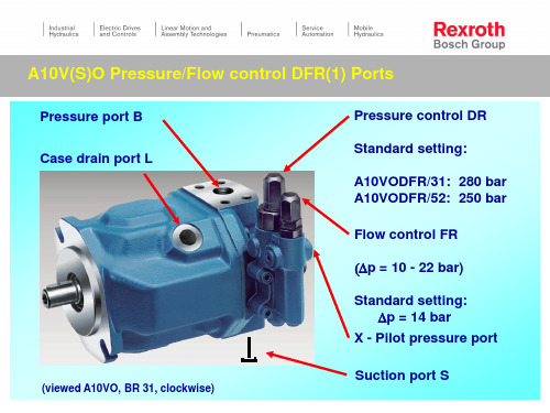
FR
DR
X - port Flow control (Standard: Dp = 14 bar);
Decompression orifice
Pressure port
Valve axis: Flow control
A10V(S)O Pressure/Flow control DFR(1) Adjustment of pressure control DR
Procedure: FR - flow control blocked ! High pressure line closed ! Adjusting of DR pressure control
with setting value !
Measuring - point 1: High pressure (measurable at plug of DR valve axis)
Adjustment DR : each rotation app. 50 bar !
- 50 bar + 50 bar
pHD
X DFR1
n = 1500 rpm Dp = 15 bar Stand by = 20 bar
px
100
125
F鰎dermenge in l/min
A10V(S)O Pressure/Flow control DFR(1) Decompression orifice and damping orifice
DFR - design With decompression orifice !
力士乐内部培训资料(PPT63页).pptx
BRI-IC Current Product range
单向型阀
单向阀应用举例:
单向阀应用举例:
高低压 选择
补油(防吸空阀)
下降
闭锁
提升
单向型阀
内泄与外泄的比较:
• 二次侧(A口)的 压力不会对控制 压力的作用产生 决定性的影响!
• 二次侧(A口)的 压力一定会对控
先导式顺序阀的结构
先导控制油经4.1作用于阀芯 5, 来改变主阀芯上腔的压力
卸荷溢流阀的结构和工作原理
❖先导阀一次开启通过球阀9; 此时阀杆6处于力平衡状态, 开启后, 主阀 上腔压力下降.
❖ 二次保持通过顶杆6; 此时, 顶杆6一侧卸荷; 顶杆6的作用面积比球阀 的作用面积大10%或17%.
• 1、Genius only means hard-working all one's life. (Mendeleyer, Russian Chemist) 天才只意味着终身不懈的努力。20.8.58.5.202011:0311:03:10Aug-2011:03
直控式液压方向阀(5-chambers)
➢线圈可拆卸的电磁铁结构:
由于电磁铁的损坏主要为线圈的烧毁,所以线圈可更换结构可使 更换线圈方便,费用降低。
➢换向时间可调(柔性换向):
➢(对湿式电磁铁结构)可通过在给电磁铁充油的流道中装入固定 式节流嘴或可调式的节流阀可调节阀的换向时间(可延长至100ms 以上), 但这个时间也受系统的温度,压力和粘度的影响。
– 弹簧对中
• 内外控制 • 阀芯卡死
液压对中
先导级减压阀:
• 先导控制阀P口的 压力也不能超过 允许的最高控制 压力, 否则应在P 口装入一个减压 阀(45 bar)
00_力士乐讲座(挖掘机)01
Interaction of consumers:用户之间的影响: -pressure summation -泵的压力为两个用户的压力之和 - consumer 2 - flow and pressure efficiency dependent from consumer -用户1的效率 影响用户2。 -效率低
李启兵:
工程机械
Control Concepts:负荷敏感,闭芯系统
泵的排量为 系统所需 饱和状态 不饱和状态
李启兵:
工程机械
控制起点/控制范围: Start of control / control range: - load independent 与负载无关 -flow independent start -控制起点与流量大小无关 flow dependent control range
李启兵:
工程机械
方向控制阀:手动、机控、电控、电液比例、伺服控制 多路阀:节流控制、负荷敏感,LUDV(与负载无关的流量分配
开式系统的特点:
吸油管路管径大,较短。 转速:由于吸油压力而受限制(可参考说明书上的吸油曲线)。 方向阀通径的大小由系统流量决定。 过滤器/冷却器的尺寸也由Q的大小来决定(有时采用单独旁路节流过 滤/冷却形式, 尤其是较大功率的系统)。 油箱的容积较大:约为系统Q的3(中、低压)-5(高压)倍(另 外还需考虑 管路及蓄能器的容积)。 泵的安装位置:上置,旁置或下置,需考虑它对吸油压力的影响! 负载的平衡靠回油管路上的背压或平衡阀来实现。
用户之间的影响: Interaction of consumers: - low pressure consumer lowers high pressure consumer -低负载用户会降低高负载用户的速度 (不饱和状态)。
力士乐A11VLO资料说明书课件.ppt
油泵的常见故障现象及原因(针对A11VOLRDS、A11VODRS泵)
2、操作执行机构,油泵没有压力或只有待命压力。
检查电机旋向,以及油箱液位。 检查油泵X口压力,是不是没有反馈压力。 LS阀卡死在全开位置或完全拧松。 DR阀-压力切断阀卡死在全开位置或者调节不当,清洗和调节。 油泵损坏。
A11VLO...LRDS
负载敏感压差 压力切断
最小排量调节
功率调 节螺钉
A11VO 2162-e / VAV 08.99
最大排量调节
A11VO Controllers Load Sensing
LRDS
Dp
主控制阀块 M4, M7 (负载感应节流孔)
orifice
负载感应 压力切断 功率调节
A11VO 2178-e / 10.99
液压介质不相容。例如,磷酸脂用丁腈橡胶密封,两者发生化学反 应。表象是泄漏处有絮状物。
联轴器没装好,有侧向力引起轴封单边磨损而漏油。表象是明显的 一侧磨损,另一侧没有磨损。
自然老化,失去弹性。表面龟裂,裂口。
油泵的常见故障现象及原因(针对A11VOLRDS、A11VODRS泵) 5、噪音、发热、泵损坏问题。
油泵的常见故障现象及原因(针对A11VOLRDS、A11VODRS泵)
3、油泵输出流量不足 。
油泵磨损,泄露量超标。 LR恒功率阀调节不当,功率设定值太小。重新调节 驱动电机转速丢失。 油泵最大流量调节不对。向外松,排量加大;向里紧,排量减小。
油泵的常见故障现象及原因(针对A11VOLRDS、A11VODRS泵)
力士乐液压培训资料ppt课件

带速无排量
发动机升速-车提速
爬坡自动降速
自动功率匹配(高载时自 动降速),合理的功率分配 (行走与工作机构)。
极限载荷调节(最大载
荷限制)
人工功率分配(寸进功能/ 与HW/EP/HD的匹配)
其202它0年如4月:1最5日佳星期油三耗等功能.
5
DA-控制的结构和工作原理
• 补油泵的 流量Q正 比于发动 机的转速。
变矩范围
多为定量马达,所以变量范围较小
可利用变量马达,和改变减速机 的传动比来获得大的变矩范围
马达受力情况
除转矩,还承受工作机构的径向/ 轴向力、弯矩、比较恶劣
马达只承受转矩,由减速机承受 工作机的径向和轴向力等,受力
较好。
制动器与机械离 可带制动器,但由于制动力矩较 可带制动器和离合器,由于制动
合器
2020年4月15日星期三
22
• 补油压力
pst 基本
恒定。
2020年4月15日星期三
6
DA-控制的结构和工作原理
• p(即作用 力F)正比于 Q 和发动机 的转速n。
2020年4月15日星期三
F
7
DA-控制的结构和工作原理
2020年4月15日星期三
8
DA-控制的结构和工作原理
2020年4月15日星期三
9
DA-控制的结构和工作原理
2020年4月15日星泄期漏三 油压力:PL=4 bar(绝对压力)
3Leabharlann 短时(例如:起动时)允许到6 bar
压力截断与高压溢流
压力切断、高压溢流(补油阀、拖车功 能):
控制形式:HD;HW;DA;DG;EZ; EP
2020年4月15日星期三
负载敏感多路阀原理
负载敏感多路阀原理引言:负载敏感多路阀(Load-Sensitive Multiple Orifice Valve)是一种在流体系统中广泛使用的控制元件,其原理基于负载敏感的特性,可以实现对流体流量的精确调节和分配。
本文将介绍负载敏感多路阀的原理、工作方式以及在实际应用中的优势。
一、负载敏感多路阀的原理负载敏感多路阀的原理基于流体在通过阀体时的压力差异,通过调节阀口的大小和数量,实现对流体流量的控制。
该阀在不同负载条件下能够自动调节阀口的开启程度,从而保持稳定的流量输出。
二、负载敏感多路阀的工作方式负载敏感多路阀由多个阀口组成,每个阀口都可以独立地控制流体的通断。
当系统中的负载增加时,流体通过阀体的压力降将增大,这会导致阀口自动调整以增加流量输出。
相反,当系统中的负载减少时,流体通过阀体的压力降将减小,阀口会自动调整以减少流量输出。
通过这种方式,负载敏感多路阀能够实时监测系统的负载情况,并自动调节流量以适应负载的变化。
三、负载敏感多路阀的优势1. 精确控制:负载敏感多路阀通过自动调节阀口的大小和数量,能够实现对流体流量的精确控制。
无论负载变化多大,都能够保持稳定的流量输出。
2. 高效能耗:负载敏感多路阀能够根据负载的变化自动调节流量,避免流体过量或不足的情况,从而提高能源利用效率。
3. 系统稳定:负载敏感多路阀能够实时监测系统的负载情况,并根据负载的变化调节流量,保持系统的稳定性和可靠性。
4. 安全可靠:负载敏感多路阀在设计上考虑了各种负载情况,并能够自动调节流量以适应负载的变化,确保系统的安全运行。
5. 适应性强:负载敏感多路阀可以根据不同的应用需求进行调整和配置,适用于各种流体系统,具有较强的通用性和适应性。
结论:负载敏感多路阀作为一种流体控制元件,在现代工业自动化系统中具有重要的应用价值。
其原理基于负载敏感的特性,通过调节阀口的大小和数量实现对流体流量的精确调节和分配。
负载敏感多路阀具有精确控制、高效能耗、系统稳定、安全可靠和适应性强等优势,能够满足不同流体系统的需求。
- 1、下载文档前请自行甄别文档内容的完整性,平台不提供额外的编辑、内容补充、找答案等附加服务。
- 2、"仅部分预览"的文档,不可在线预览部分如存在完整性等问题,可反馈申请退款(可完整预览的文档不适用该条件!)。
- 3、如文档侵犯您的权益,请联系客服反馈,我们会尽快为您处理(人工客服工作时间:9:00-18:30)。
11
Beijing Road-Hydraulic System Technology Co.,Ltd.
流量分配控制
负荷敏感多路阀在流量不饱和状态下,流量的分配会受执行机构的负荷影响,大负 荷的执行机构将降低速度,甚至停止运动。这样,执行机构的运动将不能与指令信 号同步,系统操控性差。 为了改善阀的操控性能,我们改变阀的压力补偿方式,形成了与压力无关的流量分 配阀。
力士乐敏感阀M4工作联结构
ElA.-1H0yVdOr.系列控制Ma型in式Spool 18
Pilot Valves
(interchangeable
w/ Deutsch or AMP
)
Connector
Deckel A
Shock / Anti Cav.Valve
Pilot Cover B w/ Stroke Limiter
7
Beijing Road-Hydraulic System Technology Co.,Ltd.
负载传感控制原理一
A1
A2
8
Beijing Road-Hydraulic System Technology Co.,Ltd.
负载传感控制原理二
9
Beijing Road-Hydraulic System Technology Co.,Ltd.
负载传感控制原理三
M4 /SB 多路阀 FR
X - port 负荷传感 FR
DR 压力截断 DR
A10VO 31
10
Beijing Road-Hydraulic System Technology Co.,Ltd.
负载传感控制原理四 LRDS
Dp
M4, M7 多路阀
orifice
负荷传感FR (el. / hydr. remote control) 压力截断DR
4
Beijing Road-Hydraulic System Technology Co.,Ltd.
节流控制
节流型多路换向阀的特点 换向平稳 无冲击 微调特性好 结构简单 成本低 流量受负载 进口压力影响大 压力损失大,片数越多 流量越大 压力损失越大 应用 小功率传动 无需调速控制的系统
Deckel B
Load Check Function
Pressure Compensator
LS-Pressure Relief Valves (A/B)
LS-Check Valve
Beijing Road-Hydraulic System Technology Co.,Ltd.
M4 流量调节
Number of shims
负载敏感阀M4阀体结构
End Cover standard
int. pilot oil supply
ext. pilot oil supply
Pilot Cover (A) w/ integrated
electronics
electrohydraulic hydraulic
El.-prop. Pressure Limitation
Beijing Road-Hydraulic System Technology Co.,Ltd.
负载敏感阀
负载敏感阀讲解及应用案例
乔晓斌
2010-07-26
1
BM4e-i1ji2ngCoRmpoeatdi-tHioyndraulic System Technology Co.,Ltd.
国外生产负载敏感阀公司
p (pressure Compensator)
0 shim: 130 psi
11952bsahprismi:
P
12107,4s5hpibsmaisr:
12 bar
17
Beijing Road-Hydraulic System Technology Co.,Ltd.
LS负载敏感控制
F
A
B
A, p
12
Beijing Road-Hydraulic System Technology Co.,Ltd.
SUCCESS
THANK YOU
2019/6/18
Beijing Road-Hydraulic System Technology Co.,Ltd.
流量分配控制原理
14
Beijing Road-Hydraulic System Technology Co.,Ltd.
Hydraulics
2
BM4e-i1ji2ngCoRmpoeatdi-tHioyndraulic System Technology Co.,Ltd.
国外生产负载敏感阀性能比较
阀的功能 控制性能
400bar Version adjustable Δ p Standard (Lever, hydr. er.hydr.) CAN-Bus easy to maintenance Worldwide Service
5
Beijing Road-Hydraulic System Technology Co.,Ltd.
节流控制原理
6
Beijing Road-Hydraulic System Technology Co.,Ltd.
负荷敏感多路换向阀
特点 负荷敏感控制 系统节能 多个执行结构同时动作,流量与负载无关 每个阀芯可单独设置流量 压力 微调性能好 当系统出现流量不饱和时(泵供给的流量小于同时工作的执行结构所需流量), 大负载执行结构流量先减少。不能实现执行机构的同步操作要求。
Inlet Elements
Closed Center midinlet
with Priority
Closed Center mid-inlet
End Cover standard w/ power beyond
15
Beijing Road-Hydraulic System Technology Co.,Ltd.
M4-12
✔
✔
✔✔Βιβλιοθήκη ✔✔PVG32
✔
✔
✔
Parker Voac L90
✔
✔
✔
Parker Apitech VPL
✔
✔
✔
HAWE PSV
✔
✔
3
Beijing Road-Hydraulic System Technology Co.,Ltd.
液压系统控制 – 阀式系统
节流控制 负荷传感控制(LS) 流量分配控制(LUDV)
T
T
X
Y P
MA MB
p Control
