以太网交换机,6个TP RJ45端口,2个FO端口
6口百兆以太网供电交换机(PoE交换机)说明书

6口百兆以太网供电交换机 (PoE交换机),采用高质量高速率的网络IC以及最具稳定性的PoE芯片,交换机融入了最新的AI功能, 配有两种端口优先级,PoE优先级和网络优先级,一键智能。
PoE口满足802.3af或802.3at标准, 增加功率占用指示灯,可快速了解产品整体功耗。
本系列PoE交换机能为10/100M以太网提供无缝连接,且PoE供电端口可以自动检测符合IEEE802.3af或IEEE802.3at标准的的受电设备并为其供电,非PoE设备智能检测不供电,只传输数据。
主要特点应用环境n4个百兆PoE口+2个百兆上行网口n符合IEEE 802.3、IEEE 802.3u、IEEE802.3x标准n以太网端口支持10/100M自适应n PoE端口在VLAN和Extend模式下, 自动开启AI模式n流控方式:全双工采用IEEE 802.3x标准,半双工采用Back pressure标准n支持端口自动翻转(Auto MDI/MDIX)n零配置特性,自动供给到自适应的设备n面板指示灯监控工作状态及帮助故障分析n附带三档一键智能拨码开关,支持VLAN,Normal,Extend三种模式n支持端口防雷Surge:共模4KV;静电ESD: 空气8KV, 接触6KV 城域光纤宽带网:电信、有线电视、网络系统集成等数,据网络运营商宽带专网:适用于金融、政府、石油、铁路、电力、公安、交通、教育等行业专网多媒体传输:图像、话音、数据综合传输、适用于远程 教学、会议电视、可视电话等应用实时监控:实时控制信号、图像及数据同时传输技术参数输入/输出接口电源AC INPUT (100-240 V)以太网4个百兆PoE网口2个百兆上联网口性能背板带宽 1.2Gbps包转发率0.8928Mpps包缓存448KMAC地址表2K巨型帧2048bytes转发模式存储转发MTBF100000 小时标准网络协议IEEE802.3 (以太网)IEEE802.3u (快速以太网)IEEE802.3x (流量控制)PoE协议IEEE802.3af (15.4W)IEEE802.3at (30W)行业标准EMI: FCC Part 15 CISPR (EN55032) class AEMS: EN61000-4-2 (ESD)、EN61000-4-4 (EFT)、IEN61000-4-5 (Surge)网络介质10Base-T : Cat3、4、5类或以上UTP/STP(≤100m)100Base-TX : Cat5 类或以上UTP/STP(≤100m)认证安全认证CE、FCC、RoHS环境标准工作环境工作温度:-20~50°C存放温度:-40~70°C工作湿度 :10%~90%,无冷凝存放湿度:5%~95%,无冷凝工作高度:最大10,000 英寸存放高度:最大10,000 英寸物理规格结构尺寸产品尺寸:200*118*44mm包装尺寸:245*190*60mm产品净重:0.6 KG产品毛重:0.9 KG装箱信息外箱尺寸:505*320*400mm装箱数量:20台装箱重量:19KG电源电压输入电压 : AC 100-240 V电源功率:52V1.25A装箱清单交换机1台、电源线1条、说明书、合格证1本功能指示指示灯PWR(电源指示),拨码灯,绿灯(链路&数据),黄灯(PoE/1000M)、功率指示灯拨码开关VLAN:1-4口实现监控网络下联口互相隔离,与5、6上联口互通,保护内网安全Genius PoE: 端口序列在前的优先PoE供电,同时开启PoE看门狗,视频画面中断时支持摄像机远程复位启动Extend: 1-4口实现延长网线传输距离250米订购信息HR100-AF-42N6口百兆智能型标准PoE交换机面板说明产品应用附录拨码开关V G E 状态模式下下下灭标准交换下上下灭PoE看门狗下下上慢闪Extend下上上慢闪Extend+PoE看门狗上下下常亮VLAN上上下常亮VLAN+PoE看门狗上下上快闪VLAN+Extend上上上快闪VLAN+Extend+PoE看门狗PWR(电源指示红灯)常亮:设备通电不亮:设备不通电MAX 功率指示灯绿灯亮:P<25%;黄灯亮:25%<P<50%;橙灯亮:50%<P<75%;红灯亮:P>75%1-6(绿灯)常亮:10/100M链路连接闪亮:数据传输不亮:链路不通1-4(黄灯)常亮:PoE供电正常不亮:PoE不供电5-6(黄灯)常亮:10/100M链路连接闪亮:数据传输不亮:链路不通。
6口非网管全千兆以太网交换机的详细描述:

6口非网管全千兆以太网交换机的详细描述:OFS-GSF2T4 系列6口非网管全千兆以太网交换机OFS-GSF2T4 全千兆6口以太网交换机有4个10/100/1000M自适应RJ45接口和2个1000M标准SFP插座,用户可根据需要选用不同的SFP模块,例如1000Base-T、1000Base-SX、1000Base-LX 等。
交换机采用美国最新IC,性能稳定,质量优良,使用简单方便、具有较高的性价比。
适用于小型光纤以太网和有特别需要的光纤网络中。
主要特点◆4个RJ45 电口和2个SFP插口,实现双绞线和光纤之间,及各端口之间的以太网信号的无缝连接◆RJ45电口能自适应10/100/1000M、全/半双工模式、直通线/交叉线连接方式◆SFP口支持1000M全双工模式◆支持流量控制,能防止广播风暴◆支持VLAN,QoS,TPv4, TPv6◆支持最大10K byte的超长信息包◆功耗小(6W),发热少,稳定性好。
技术规范◆适合标准:IEEE802.3/u/z/ab,10Base-T, 100Base-TX, 1000Base-T和1000Base-SX/LX◆MAC地址表:1K◆缓存:1MKb◆背板带宽:12G,可实现无阻塞线速转发◆接口标准:电口:RJ-45,10/100/1000Mbps(自适应);SFP口:1000Mbps;◆缆线:双绞线:5E类线或6类线(最长距离至100米)光纤(多模):50/125,62.5/125μm(最长距离至550/224米)光纤(单模):8/125,8.7/125,9/125μm(最长距离10~100千米)◆流量控制:全双工IEEE802.3x流量控制;半双工背压流量控制◆LED指示灯:PWR ,SFP1 Link/Act,SFP2 Link/Act;TP1~TP4 Link/Act,TP1~TP4 100/1000,TP1~TP4 10/100;◆电源: 交流220V(100-240V),50~60Hz;直流:5V,2A◆环境温度::0 ~+50℃;◆存储温度::-40 ~+70℃;◆湿度::5% ~90%;◆体积:30(高)×140(宽)×100(长)mm;定货信息产品型号产品描述OFS-GSF2T4 6口10/100/1000M自适应以太网光纤交换机,4个自适应RJ45电口和2个千兆SFP插口。
TP-LINK 万兆交换机 TL-SH1226 产品说明书

TL-SH122624个10/100/1000M⾃适应RJ45端⼝,2个万兆SFP+光纤模块扩展插槽•所有端⼝均具备线速转发能⼒•⽀持端⼝⾃动翻转(Auto MDI/MDIX)功能•⽀持通过拨动开关切换交换机⼯作模式•即插即⽤,可上机架产品简介TL-SH1226是TP-LINK⾃主研发的万兆上联⾮⽹管以太⽹交换机产品,提供24个10/100/1000M RJ45端⼝和2个万兆 SFP+光纤模块扩展插槽,具备每端⼝线速转发能⼒。
该系列交换机针对视觉安防、⽆盘启动及⽆线组⽹等应⽤提供不同⼯作模式,具备良好的⽹络适应能⼒。
端⼝性能提供24个10/100/1000M ⾃适应RJ45端⼝和2个万兆上⾏SFP+光纤模块扩展插槽,所有端⼝均可实现线速转发;每端⼝均⽀持MDI/MDIX⾃动翻转及双⼯/速率⾃协商;⽀持IEEE 802.3x全双⼯流控和Backpressure半双⼯流控。
三种⼯作模式提供模式切换开关,⽀持“标准交换”、“VLAN隔离”和“⽹络克隆”三种⼯作模式,可优化⽀持视觉安防、⽆盘启动及⽆线组⽹等多种应⽤场景。
使⽤简单19英⼨标准机架安装,即插即⽤,⽆需管理;动态LED指⽰灯,提供简单的⼯作状态提⽰及故障排除⼿段。
万兆交换机01我们会将各产品的升级软件或驱动程序及时发布在TP-LINK官⽅⽹站上,您可以在上得到技术⽀持,免费下载最新版本的最新软件或驱动程序。
TP-LINK公司将全⼒检查印刷和图⽚中的错误,但对于可能出现的疏漏,TP-LINK概不负责。
本⻚所列产品外观、规格、参数、价格及产品供应状况随时更改,恕不另⾏通知。
万兆交换机(本⻚为最后⼀⻚)02。
莫加工业级6口PoE以太网交换机产品说明书

P/N: 1802002060016 *1802002060016*EDS-P206A-4PoE Series Quick Installation GuideMoxa EtherDevice TM SwitchVersion 4.3, May 2021Technical Support Contact Information/support2021 Moxa Inc. All rights reserved.OverviewThe EDS-P206A-4PoE series industrial Ethernet switches are entry-level industrial 6-port PoE Ethernet switches that support IEEE 802.3, IEEE 802.3u, and IEEE 802.3x, with 10/100M, full/half-duplex, MDI/MDIX auto-sensing, IEEE 802.3af, and IEEE 802.3at.The EDS-P206A-4PoE series provides 12/24/48 VDC redundant power inputs that can be connected simultaneously to a live DC power source. The switches are available with a standard operating temperature range from -10 to 60°C, or with a wide operating temperature range from -40 to 75°C, and their IP30 metal housing makes them rugged enough for any harsh industrial environment.To provide greater versatility for use with applications from different industries, the EDS-P206A-4PoE switches also allow users to enable or disable broadcast storm protection with DIP switches on the outer panel.The EDS-P206A-4PoE switches can be easily installed on a DIN-Rail or in distribution boxes. The DIN-Rail mounting capability and IP30 metal housing with LED indicators make the plug-and-play EDS-P206A-4PoE switches reliable and easy to use.NOTE Throughout this Hardware Installation Guide, we use EDS as an abbreviation for Moxa EtherDevice Switch:EDS = Moxa EtherDevice SwitchPackage ChecklistYour EDS is shipped with the following items. If any of these items are missing or damaged, please contact your customer service representative for assistance.•Moxa EtherDevice™ Switch•Quick installation guide (printed)•Warranty cardFeaturesHigh-wattage Power-over-Ethernet•Up to 30 watts per PoE port•Active circuit protection•Auto disconnection for over-voltage or under-voltage•Power consumption detection and classificationHigh Performance Network Switching Technology•10/100BaseT(X) (RJ45 connector), 100BaseFX (SC/ST connector, multi/single-mode)•10/100M, Full/Half-Duplex, MDI/MDIX auto-sensing•IEEE 802.3/802.3u/802.3x•Store and Forward switching process type, 2K address entries Rugged Design•Redundant dual 12/24/48 VDC power input•Operating temperature range from -10 to 60°C, or extended operating temperature of -40 to 75°C for “T” models.•IP30 metal housing•DIN-Rail or panel mounting capabilityEDS-P206A-4PoE (Standard) Panel Layouts1.Grounding screw2.Terminal block for powerinput P1/P23.DIP switches4.Power input P1 LED5.Power input P2 LED6.PoE LED7.10/100BaseT(X) port8.TP port’s 10/100 MbpsLED9.Model name10.Screw hole for wallmounting kit11.DIN-Rail kitEDS-P206A-4PoE-M-SC/ST Panel LayoutsNOTE: The EDS-P206A-4PoE-S-SC/ST are identical in appearance to the EDS-P206A-4PoE-M-SC/ST.1.Grounding screw2.Terminal block for powerinput P1/P23.DIP switches4.Power input P1 LED5.Power input P2 LED6.PoE LED7.10/100BaseT(X) port8.TP port’s 10/100 MbpsLED9.Model name10.100BaseFX port11.FX port’s 100 Mbps LED12.Screw hole for wallmounting kit13.DIN-Rail kitEDS-P206A-4PoE-MM-SC/ST Panel Layouts NOTE: The EDS-P206A 4PoE-SS-SC/ST are identical in appearance to the EDS-P206A-4PoE- MM-SC/ST.1.Grounding screw Array2.Terminal block for powerinput P1/P23.DIP Switches4.Power input P1 LED5.Power input P2 LED6.PoE LED7.10/100BaseT(X) port8.TP port’s 10/100 MbpsLED9.Model name10.100BaseFX port11.FX port’s 100 Mbps LED12.Screw hole for wallmounting kit13.DIN-Rail kitMounting DimensionsUnit = mm (inch)DIN-Rail MountingThe aluminum DIN-Rail attachment plate should already be fixed to the back panel of the EDS when you take it out of the box. If you need to reattach the DIN-Rail attachment plate, make sure the stiff metal spring is situated towards the top, as shown in the figures below. STEP 1: Insert the top of the DIN-Rail into the slot just below the stiff metal spring.STEP 2: The DIN-Rail attachment unit will snap into place as shown below.To remove the EDS from the DIN-Rail, reverse Steps 1 and 2 above.Wall Mounting (optional)For some applications, you will find it convenient to mount the EDS-P206A-4PoE on the wall, as shown in the following figures. STEP 1: Remove the aluminum DIN-Railattachment plate from the EDS-P206A-4PoE’s rear panel, and then attach the wall mount plates as shown in the diagram at the right.STEP 2: Mounting the EDS-P206A-4PoE on the wall requires 4 screws. Use the switch, with wall mount plates attached, as a guide to mark the correct locations of the 4 screws. The heads of the screws should be less than 6.0 mm in diameter, and the shafts should be less than 3.5 mm in diameter, as shown in the figure at the right.NOTE Before tightening the screws into the wall, make sure the screw head and shank size are suitable by inserting the screw into one of the keyhole-shaped apertures of the wall mounting plates.Do not screw the screws in completely—leave about 2 mm to allowroom for sliding the wall mount panel between the wall and the screws. STEP 3: Once the screws are fixed in the wall, insert the four screw heads through the large parts of the keyhole-shaped apertures, and then slide the EDS-P206A-4PoE downwards, as indicated. Tighten the four screws for added stability.Wiring RequirementsYou should also pay attention to the following points: •Use separate paths to route wiring for power and devices. If power wiring and device wiring paths must cross, make sure the wires are perpendicular at the intersection point.NOTE: Do not run signal or communications wiring and power wiring in the same wire conduit. To avoid interference, wires with different signal characteristics should be routed separately. •You can use the type of signal transmitted through a wire todetermine which wires should be kept separate. The rule of thumb is that wiring that shares similar electrical characteristics can be bundled together.• Keep input wiring and output wiring separated.•We strongly advise labeling the wiring to all devices in the system.Grounding the EtherDevice SwitchGrounding and wire routing help limit the effects of noise due toelectromagnetic interference (EMI). Run the ground connection from the ground screw to the grounding surface prior to connecting devices.Wiring the Redundant Power InputsThe top two contacts and the bottom two contacts of the 4-contactterminal block connector on the EDS’s top panel are used for the EDS’s two DC inputs. Top and front views of one of the terminal block connectors are shown here.STEP 1: Insert the negative/positive DC wires into the V-/V+ terminals.STEP 2: To keep the DC wires from pulling loose, use a small flat-blade screwdriver to tighten the wire-clamp screws on the front of the terminal block connector.STEP 3: Insert the plastic terminal block connector prongs into the terminal block receptor, which is located on EDS’s top panel.Communication ConnectionsThe EDS-P206A-4PoE switches have 4, 5, or 6 10/100BaseT(X) Ethernet ports, and 2, 1, or 0 (zero) 100BaseFX multi/single-mode (SC/ST-type connector) fiber ports.10/100BaseT(X) Ethernet Port Connection10/100BaseT(X) ports located on the EDS’s front panel are used to connect to Ethernet-enabled devices. Below we show pinouts for both MDI (NIC-type) ports and MDI-X (HUB/Switch-type) ports, and also show cable wiring diagrams for straight-through and cross-over Ethernet cables. MDI Port Pinouts MDI-X Port Pinouts8-pin RJ45Pin Signal 1 Tx+ 2 Tx- 3 Rx+ 6Rx-Pin Signal 1 Rx+ 2 Rx- 3 Tx+ 6Tx-PoE 10/100BaseT(X) Ethernet Port ConnectionPoE 10/100BaseT(X) ports located on the EDS switch’s front panel are used to connect to PoE-enabled devices. The pinout follows the “Alternative A, MDI mode” of 802.3af/at standards. Please see the details in the following table. PoE Port Pinout8-pin RJ45Pin Data Power 1 Tx+V+ 2 Tx- V+ 3 Rx+ V- 6Rx-V-NOTE According to IEEE 802.3af/at standards, the PD shall be implemented to be insensitive to the polarity of the power supply and shall be able to operate per MDI mode and MDI-X mode. However, some PDs only support MDI mode or MDI-X mode only. The following figure shows how to select the correct cable between the PD and EDS-P206A-4POE.RJ45 (8-pin) to RJ45 (8-pin) Straight-Through Cable WiringRJ45 (8-pin) to RJ45 (8-pin) Cross-Over Cable WiringNOTE If the PD only supports MDI-X mode (V-, V-, V+, V+ for pins 1, 2, 3, 6), choose a cross-over Ethernet cable to connect the PD and the EDS switch. If the PD only supports MDI mode (V+, V+, V-, V- for pins 1, 2, 3, 6), choose a straight-through Ethernet cable between the PD and the EDS-P206A-4PoE switch.100BaseFX Ethernet Port ConnectionThe concept behind the SC/ST port and cable is straightforward. Suppose you are connecting devices I and II; contrary to electricalsignals, optical signals do not require a circuit in order to transmit data. Consequently, one of the optical lines is used to transmit data from device I to device II, and the other optical line is used transmit data from device II to device I, for full-duplex transmission.Remember to connect the Tx (transmit) port of device I to the Rx(receive) port of device II, and the Rx (receive) port of device I to the Tx (transmit) port of device II. If you make your own cable, we suggest labeling the two sides of the same line with the same letter (A-to-A and B-to-B, as shown below, or A1-to-A2 and B1-to-B2). SC-Port PinoutsSC-Port to SC-Port Cable WiringST-Port Pinouts ST-Port to ST-Port Cable WiringRedundant Power InputsBoth power inputs can be connected simultaneously to live DC power sources. If one power source fails, the other live source acts as a backup, and automatically supplies all of the EDS’s power needs. DIP Switch SettingsThe default setting for each DIP Switch isOFF. The following table explains the effectof setting the DIP Switches to the ONpositions.DIP SwitchSetting Description ––Serves no function (reserved for future use). BSPON Enables broadcast storm protection OFF Disables broadcast storm protectionLED IndicatorsThe front panel of the EDS switches contains several LED indicators. The function of each LED is described in the following table.LED Color State DescriptionP1 AMBER OnPower is being supplied to power inputP1.OffPower is not being supplied to powerinput P1.P2 AMBER OnPower is being supplied to power inputP2.OffPower is not being supplied to powerinput P2.10/100 AMBEROn TP port’s 10 Mbps link is active.Blinking Data is being transmitted at 10 Mbps.Off TP port’s 10 Mbps link is inactive. GREENOn TP port’s 100 Mbps link is active.Blinking Data is being transmitted at 100 Mbps.Off TP port’s 100 Mbps link is inactive.PoE+ AMBEROnThe PoE device is connected by theIEEE 802.3af standardBlinkingThe PoE power is shut off becausethere is insufficient powerOffNo PoE power output or no PoEconnected devicesGreenOnThe PoE device is connected by theIEEE 802.3at standardOffNo PoE power output or no PoEconnected devicesRedBlinkingPoE failure:-1 time/sec: PoE standard detectionfailure-2 times/sec: PoE current overload Off No PoE failureAuto MDI/MDI-X ConnectionThe Auto MDI/MDI-X function allows users to connect the EDS’s10/100BaseTX ports to any kind of Ethernet device, without needing to pay attention to the type of Ethernet cable being used for the connection. This means that you can use either a straight-through cable or cross-over cable to connect the EDS to Ethernet devices.Dual Speed Functionality and SwitchingThe Moxa EtherDevice Switch’s 10/100 Mbps switched RJ45 port auto negotiates with the connected device for the fastest data transmission rate supported by both devices. All models of Moxa EtherDevice Switch are plug-and-play devices, so that software configuration is not required at installation, or during maintenance. The half/full duplex mode for the switched RJ45 ports is user dependent and changes (by auto-negotiation) to full or half duplex, depending on which transmission speed is supported by the attached device. Broadcast Storm ProtectionThe EDS-P206A-4PoE Series has a built-in algorithm for limiting the amount of broadcast packets through the switch. This function is by default disabled and can be enabled by turning on the DIP switch labeled “BSP” on the top cover. If the broadcast storm protection algorithm detects more than 1k broadcast frames per second, then the switch will be suppressed from receiving broadcast frames for a period of 2 ms to prevent any further flooding.Switching, Filtering, and ForwardingEach time a packet arrives at one of the switched ports, a decision is made to either filter or forward the packet. Packets with source and destination addresses belonging to the same port segment will be filtered, constraining those packets to one port, and relieving the rest of the network from the need to process them. A packet with destination address on another port segment will be forwarded to the appropriate port, and will not be sent to ports where it is not needed. Packets that are used in maintaining the operation of the network (such as the occasional multi-cast packet) are forwarded to all ports. The EDS operates in the store-and-forward switching mode, which eliminates bad packets and enables peak performance to be achieved when there is heavy traffic on the network.Switching and Address LearningThe EDS has an address table that can hold up to 1024 addresses, which makes it suitable for use with large networks. The address tables are self-learning, so that as nodes are added or removed, or moved from one segment to another, the EDS automatically keeps up with new node locations. An address-aging algorithm causes the least-used addresses to be deleted in favor of newer, more frequently used addresses. To reset the address buffer, power down the unit and then power it back up.Auto-Negotiation and Speed SensingAll of the EDS’s RJ45 Ethernet ports independently support auto-negotiation for speeds in the 10BaseT and 100BaseTX modes, with operation according to the IEEE 802.3u standard. This means that some nodes could be operating at 10 Mbps, while at the same time, other nodes are operating at 100 Mbps. Auto-negotiation takes place when an RJ45 cable connection is made, and then each time a LINK is enabled. The EDS advertises its capability for using either 10 Mbps or 100 Mbps transmission speeds, with the device at the other end of the cable expected to advertise in a similar manner. Depending on what type of device is connected, this will result in agreement to operate at a speed of either 10 Mbps or 100 Mbps. If an EDS RJ45 Ethernet port is connected to a non-negotiating device, it will default to 10 Mbps speed and half-duplex mode, as required by the IEEE 802.3u standard. Total Power BudgetFor the total power budget, the EDS-P206A-4PoE will have 62 W at 12-17 VDC input, and 120 W at 18-57 VDC input. The total power budget is the total amount of reserved PoE power based on the PoE class of PoE device. If a newly connected PoE device causes the total reserved power to exceed the total power budget, the newly connected PoE device will be denied power.Input Voltage Total Power Budget12 VDC (12-17 VDC) 62 W24 VDC (18-35 VDC) 120 W48 VDC (36-57 VDC) 120 WPoE Class Reserved Power0 15.4 W1 4.0 W2 7.0 W3 15.4 W4 30 W SpecificationsTechnologyStandards IEEE 802.3 for 10BaseT,IEEE 802.3u for 100BaseT(X) and 100BaseFX,IEEE 802.3x for Flow ControlIEEE 802.3af for PoEIEEE 802.3at for PoE+Processing Type Store and ForwardFlow Control IEEE 802.3x flow control, back pressure flowcontrolInterfaceRJ45 Ports 10/100BaseT(X) auto negotiation speed, F/Hduplex mode, and auto MDI/MDI-X connection Fiber Ports 100BaseFX ports (SC/ST connector,multi/single-mode)LED Indicators P1, P2 (Power), 10/100M (TP port), and 100M(fiber port), PoEDIP Switch enable/disable broadcast storm protectionOptical Fiber100BaseFXMulti-mode Single-modeFiber Cable Type OM150/125 μmG.652 800 MHz*kmTypical Distance 4 km 5 km 40 kmWavelengthTypical (nm) 1300 1310TX Range (nm) 1260 to 1360 1280 to 1340 RX Range (nm) 1100 to 1600 1100 to 1600Optical PowerTX Range (dBm) -10 to -20 0 to -5 RX Range (dBm) -3 to -32 -3 to -34 Link Budget (dB) 12 29 Dispersion Penalty(dB)3 1Note: When connecting a single-mode fiber, we recommend using an attenuator to prevent damage caused by excessive optical power. Typical Distance To reach the typical distance of the specifiedfiber transceiver, please refer to the followingformula: Link budget(dB) > dispersionpenalty(dB) + total link loss(dB)PoETotal Power Budget 62 W @ 12 VDC (12-17 VDC)120 W @ 24/48 VDC (18-57 VDC)PoE Output Voltage 50 VDC @ 12/24/48 VDC power inputPoE Output Power 15.4 W for 802.3af, 30 W for 802.3atPoE Output Current 350 mA for 802.3af, 600 mA for 802.3at Overload CurrentProtection (at the port)SupportedPoE Pinout Mode A: Pair 1, 2 (V+); Pair 3, 6 (V-) PowerInput Voltage 12/24/48 VDC, redundant dual inputs Operating Voltage 12 to 57 VDCRated Current 6.19A @ 12VDC,5.55A @ 24 VDC,2.71A @ 48 VDCPower Consumption 13.2 W max., without PDs' consumption Inrush Current 64.56 A @ 48 VDC (0.1 - 1ms)Electrical Isolation 2250 VDC to chassis for 60 sHeat Dissipation 45.03 BTU/hOverload CurrentProtection (at theinput)SupportedReverse PolarityProtectionSupportedConnection 1 removable 4-contact terminal block Note: We strongly recommend using an isolated power supply with maximum output current of 7.5 A due to the power de-rating issue of the power supply at high operating temperatures.Moreover, without galvanic isolation between the redundant power inputs of this device, the V1+ and V2+ should use the same voltage.Physical CharacteristicsHousing Metal, IP30 protectionDimensions 50 x 114 x 70 mmWeight 275 gInstallation DIN-Rail Mounting, Wall Mounting (withoptional kit)Environmental LimitsOperating Temperature Standard models: -10 to 60°C (32 to 140°F) Wide temp. models: -40 to 75°C (-40 to 167°F)Storage Temperature -40 to 85°C (-40 to 185°F)Ambient RelativeHumidity5 to 95% (non-condensing)Regulatory ApprovalsSafety UL508EMI FCC Part 15, CISPR (EN55032) class AEMS IEC 61000-4-2 ESD: Contact 6 kV; Air 8 kVIEC 61000-4-3 RS: 20 V/m (80 MHz to 1 GHz)IEC 61000-4-4 EFT: Power 2 kV; Signal 1 kVIEC 61000-4-5 Surge: Power 2 kV; Signal 2 kVIEC 61000-4-6 CS: 10 VIEC 61000-4-8Shock IEC 60068-2-27Freefall IEC 60068-2-32Vibration IEC 60068-2-6WarrantyTime Period 5 yearsDetails /warrantyPatent/doc/operations/Moxa_Patent_Marking.pdf。
两光四电 1000M 光纤交换机
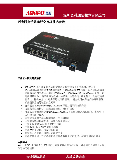
两光四电千兆光纤交换机技术参数千兆以太网光纤交换机•AOK-G2F4T 全千兆6口以太网交换机又称节点式光纤交换机,有4个10/100/1000M自适应RJ45接口和2个1000M标准SFP插座,用户可根据需要选用不同的SFP模块,例如1000Base-T、1000Base-SX、1000Base-LX等。
采用美国最新IC,高品质激光收发一体模块,性能稳定,质量优良,具有较高的性价比。
提供双光口,可实行链状结构组网,适合使用在高速公路网络系统、矿井通信系统等链状多点网络。
•自动适应10Mbps/100Mbps/1000Mbps环境,便于网络的升级•内置高效交换核心,实现流量控制,减少广播包•可提供四个独立的10M/100Mbps/1000Mbps自适应交换式双绞线口,实现电口备份和多用户接入•支持全双工和半双工传输模式,能自动协商•支持双绞线口自动交叉,方便系统调试安装•支持最长1552byte超长数据包传输•支持QoS,保证VOIP数据包传输•支持STP生成树,构成冗余网络•低功耗,低发热,能长时间稳定工作;•支持双纤多模、双纤单模和单纤单模多种光纤口选择,扩展了用户的需求。
主要特点◆4个 RJ45 电口和2个SFP插口,实现双绞线和光纤之间,及各端口之间的以太网信号的无缝连接RJ45电口能自适应10/100/1000M 、全/半双工模式、直通线/交叉线连接方式◆SFP 口支持1000M 全双工模式◆支持流量控制,能防止广播风暴◆支持VLAN ,QoS ,TPv4, TPv6◆支持最大10K byte 的超长信息包◆功耗小(6W ),发热少,稳定性好。
技术规范◆适合标准:IEEE802.3/u/z/ab ,10Base-T, 100Base-TX, 1000Base-T 和1000Base-SX/LX◆MAC 地址表:1K◆缓存:1MKb◆背板带宽:12G ,可实现无阻塞线速转发◆接口标准:电口:RJ-45,10/100/1000Mbps (自适应);SFP 口:1000Mbps ;◆缆线:双绞线:5E 类线或6类线(最长距离至100米)光纤(多模):50/125,62.5/125μm(最长距离至550/224米)光纤(单模):8/125,8.7/125,9/125μm(最长距离10~100千米)◆流量控制:全双工IEEE802.3x 流量控制;半双工背压流量控制◆LED 指示灯:PWR ,SFP1 Link/Act ,SFP2 Link/Act ;TP1~TP4 Link/Act ,TP1~TP4 100/1000,TP1~TP4 10/100;◆电源: 交流220V(100-240V),50~60Hz ; 直流:5V ,2A◆环境温度::0 ~ +50℃;◆存储温度::-40 ~ +70℃;◆湿度::5% ~ 90%;◆体积:30(高)×180(宽)×100(长)mm ;产品型号 产 品 描 述AOK-G2F4TMM 10/100/1000M 自适应以太网多模光纤交换机,4个电口和 2个多模SFP ,光波长850nm 。
华为中低端以太网交换机设备简介

华为机密, 华为机密,未经许可不得扩散
文档密级: 文档密级:内部公开
S3526E 交换机外形
正面: 正面:
24个固定的 个固定的10/100Base-TX以太网端口 个固定的 以太网端口
背面: 背面:
2ቤተ መጻሕፍቲ ባይዱ扩展模块插槽 个扩展模块插槽
可选模块(支持一个堆叠模块) 可选模块(支持一个堆叠模块)
1端口百兆以太网多模光接口模块(1310nm,2km,SC) 1端口百兆以太网单模光接口模块(1310nm,15km,SC) 1端口千兆以太网电接口模块(RJ45) 1端口千兆以太网多模光接口模块(850nm,550m,SC) 1端口千兆以太网单模光接口模块(1310nm,10km,SC) 1端口千兆以太网单模光接口模块(1550nm,40km,LC) 1端口千兆以太网单模光接口模块(1550nm,70km,LC) 1端口LANSWITCH堆叠模块
产品定位
大、中企业和城域网汇聚层
华为机密, 华为机密,未经许可不得扩散
文档密级: 文档密级:内部公开
S3526 交换机外形
正面: 正面:
24个固定的 个固定的10/100Base-TX以太网端口 个固定的 以太网端口
背面: 背面:
2个扩展模块插槽 (1000M) 个扩展模块插槽
可选模块(支持一个堆叠模块) 可选模块(支持一个堆叠模块) 1端口千兆以太网电接口模块(RJ45) 1端口千兆以太网多模光接口模块(850nm,550m,SC) 1端口千兆以太网单模光接口模块(1310nm,10km,SC) 1端口千兆以太网单模光接口模块(1550nm,40km,LC) 1端口千兆以太网单模光接口模块(1550nm,70km,LC) 1端口LANSWITCH堆叠模块
ST方式100Mbps全双工,10或100Mbps(RJ45)数据传输

宽温以太网交换机,7个TP RJ45端口,1个FO端口,ST方式100 Mbps全双工,10或100 Mbps(RJ45)数据传输速率自动检测,自动交叉功能,读取QoS优先信息,接受安全框架接口1 以太网(RJ45)端口数7 (RJ45端口)连接类型RJ45连接方法方面的注意事项自适应和自交叉传输原理以太网RJ45双绞线传输速度10/100 MBit/s接口2 光纤接口端口数 1 (FO端口)连接类型ST传输原理多模玻璃光纤传输速度100 MBit/s (ST,全双工)传输长度12.1 km (F-G 62.5/125 0.7 dB/km F1000玻璃光纤)3.3 km (F-G 62.5/125 2.6 dB/km F600 玻璃光纤)7.1 km (F-G 50/125 .7 dB/km F1200 玻璃光纤)3.1 km (F-G 50/125 1.6 dB/km F800 玻璃光纤)波长1300 nm功能基本功能非管理型交换机/自适应,遵循IEEE802.3,存储和传送交换模式,包括QoS 和报警触点状态和诊断显示LED:US1,US2(冗余电源电压),各端口的链接和活动,报警(电源和链路下行)网络扩展参数级联深度网络、线型和星型结构:任意最大导线长度(双绞线)100 m电源电压电源电压24 V DC (冗余)残波 3.6 VPP (在允许的电压范围内)供电电压范围9 V DC ... 32 V DC典型电流耗量180 mA (@24 V DC)最大电流耗量565 mA (@9 V DC)一般数据宽度50 mm高度130 mm深度100 mm安装类型DIN导轨类型AX 端子化设计重量470 g保护等级IP20环境温度(运行)-40 °C ... 75 °C环境温度(存放/运输)-40 °C ... 85 °C允许湿度(运行) 5 % ... 95 % (无冷凝)允许湿度(存放/运输) 5 % ... 95 % (无冷凝)空气压力(运行)62 kPa ... 108 kPa (最高可达海拔4160米)空气压力(存放/运输)62 kPa ... 108 kPa (最高可达海拔4160米)外壳材料铝发射干扰EN 61000-6-4 抗干扰EN 61000-6-2。
SCALANCEXF200,网管型

SCALANCE XF 200,网管型‘6GK’‘SCALANCE’‘XF-200’6GK5204-0BA00-2AF2 SCALANCE XF204,扁平,网管型 IE 交换机,4 个10/100Mbit/s RJ45 端口,故障信号触点,带设置按钮,冗余电源,PROFINET-IO 设备,网络管理,集成冗余管理器,包括手册光盘,可选 C-PLUGSIEMENS A&D:商先生手机:150****73366GK5204-2BC00-2AF2 SCALANCE XF204-2,扁平,网管型 IE 交换机,4 个10/100Mbit/s RJ45 端口,2 个 100Mbit/s FO 端口,故障信号触点,带设置按钮,冗余电源,PROFINET-IO 设备,网络管理,集成冗余管理器,包括手册光盘,可选 C-PLUGSIEMENS A&D:商先生手机:150****73366GK5206-1BC00-2AF2 SCALANCE XF206-1,扁平,网管型 IE 交换机,6 个10/100Mbit/s RJ45 端口,1 个 100Mbit/s FO 端口,故障信号触点,带设置按钮,冗余电源,PROFINET-IO 设备,网络管理,集成冗余管理器,包括手册光盘,可选 C-PLUGSIEMENS A&D:商先生手机:150****73366GK5208-0BA00-2AF2 SCALANCE XF208,扁平,网管型 IE 交换机,8 个10/100Mbit/s RJ45 端口,故障信号触点,带设置按钮,冗余电源,PROFINET-IO 设备,网络管理,集成冗余管理器,包括手册光盘,可选 C-PLUGSIEMENS A&D:商先生手机:150****7336OverviewSCALANCE XF-200 系列网管型工业以太网交换机最佳适用于构建总线形、星形和环形拓扑结构的 10/100 Mbit/s 工业以太网可使用集成冗余管理器构建具快速介质冗余性的快速以太网环形拓扑结构站或网络的电气和光学接口与设备的端口类型一致。
各种类型的网络交换机接口介绍

各种类型的网络交换机接口介绍网络交换机是现代计算机网络中不可或缺的一个组件,它负责将数据包准确地转发到目标设备。
在现代网络中,各种类型的网络交换机接口都被使用到,以下就是一些常见网络交换机接口的介绍。
1. 以太网接口以太网接口是一种最广泛使用的接口,以太网交换机通过这种接口以太网数据链路层进行数据传输。
以太网接口通常采用RJ45插头,支持10/100/1000Mbps的速率,而新的以太网交换机还支持10GbE速率。
RJ45插头接口是最常见的,大多数市场上的以太网交换机都提供这种接口。
2. SFP接口SFP (Small form-factor pluggable) 接口是一种插拔式的光模块接口。
它是一种可替换的接口,支持光纤和铜缆的连接。
SFP 接口由两个部分组成,一个是SFP 模块,另外一个是SFP 插槽,SFP 模块插入SFP 插槽中再进行数据传输。
3. QSFP/QSFP+接口QSFP (Quad Small Form-factor Pluggable) 是一种光模块接口,主要用于高速网络传输中。
QSFP 接口可以在四个10Gbps 通道之间进行切换,最高可支持传输速率为40Gbps,而QSFP+ 接口则支持最高100Gbps 速率。
4. HDMI接口HDMI (High-Definition Multimedia Interface) 接口是一种数字信号传输接口,主要用于连接计算机和高清电视以及其他多媒体设备。
HDMI 接口同时可以传输音频和视频信号,因而它在高清视频传输中得到广泛应用。
5. USB接口USB (Universal Serial Bus) 接口是一种普遍被使用的电脑&移动设备接口,它主要用于数据传输和充电。
USB 接口的传输速率从 1.5Mbps 到20Gbps 不等,新版的USB 3.1 接口更支持10Gbps 速率,因此USB 接口成为常见的接口之一。
6. 光口接口光口接口是一种在网络中使用的传输数据的接口,它利用光电转换技术将网络信息转化为光信号,再通过光纤传输。
三旺IES608-2F工业交换机
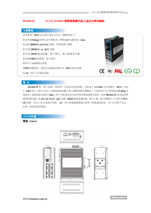
工业光数据网络通信解决方案IES608-2F 6+2口10/100M 网管型智能冗余工业以太网交换机 ◎支持6个RJ45以太网口和2个光口(SC/ST 接口) ◎支持SW-Ring 环网冗余专利技术,网络故障自愈时间<20ms ◎支持IEEE802.1Q VLAN 设置,有效控制广播域 ◎支持IEEE802.1p_QOS 功能◎支持IGMP 静态组播、端口聚合、端口镜像等功能 ◎支持WEB 界面设置,易于管理 ◎符合工业4级设计要求◎IP30等级防护,波纹式高强度金属外壳,DIN 卡轨式安装 ◎-40~75℃工作温度范围IES608-2F 是一款工业级、网管型、冗余以太网交换机,支持6个10/100M 以太网端口(RJ45)和2个100M 光口(接口可选),2路电源备份输入和1路继电器告警输出。
产品采用了自主研发的SW-Ring 环网技术(网络故障自愈时<20ms )用户可轻易设定冗余环网以增加网络可靠性,此外IES608-2F 还支持多种网络管理功能,如802.1Q VLAN 、QoS 功能、IGMP 静态组播功能、端口汇聚、端口镜像等。
产品符合FCC 、CE 标准,符合工业4级设计要求,-40~75℃的宽温能够满足各种工业现场的要求,可广泛应用于电力、水利、轨道交通等领域。
单位(mm )技术:标准:IEEE802.3、IEEE802.3u 、IEEE802.3x 、IEEE802.1Q 、IEEE802.1p 、IEEE802.3D 、IEEE802.3W流量控制:IEEE802.3x 流控、背压流控 传输方式:存储转发 系统交换带宽:2.0G MAC 地址表:2K 接口:RJ45口:10Base-T/100Base-TX 自动流速控制,全/半双工模式和MDI/MDI-X 自动侦测光纤接口:100Base-FX 口(SC/ST 接口)程序加载口:基于串口全局网管(RS-232),RJ45 告警输出接口:1路继电器告警信息输出,电流负载能力1A@30VDCLED 指示灯:PWR1、PWR2、Alarm 、Run 、10/100M 、Link/ACT 、Link 7、Link 8电源:输入电压:24VDC (12~36VDC )支持双电源备份内置过流保护工作环境:工作温度:-40~75℃ 存储温度:-40~85℃ 相对湿度:5%~95%(无凝露) 机械结构:外壳:IP30防护等级,波纹式高强度金属外壳 安装:DIN 卡轨式安装尺寸(W×H×D ):136 mm ×52mm ×105mm 通过认证:EMI :FCC Part 15,CISPR (EN55022) class A EMS :EN61000-4-2 (ESD),Level 4EN61000-4-3 (RS),Level 4 EN61000-4-4 (EFT),Level 4 EN61000-4-5 (Surge),Level 4 EN61000-4-6 (CS),Level 4 EN61000-4-8,100 A/m EN61000-4-11 冲击:IEC60068-2-27自由落体:IEC 60068-2-32震动:IEC60068-2-6保修期:5年 IES608-2F(SSC): 百兆网管型智能冗余工业以太网交换机、6口10-BaseT/100Base-TX 、2口单模100Base-FX 、SC 接口、DIN 卡轨式安装、DC12~36V 双电源备份输入IES608-2F(SST): 百兆网管型智能冗余工业以太网交换机、6口10-BaseT/100Base-TX 、2口单模100Base-FX ,ST 接口、DIN 卡轨式安装、DC12~36V 双电源备份输入IES608-2F(MSC):百兆网管型智能冗余工业以太网交换机、6口10-BaseT/100Base-TX 、2口多模100Base-FX ,SC 接口、DIN 卡轨式安装、DC12~36V 双电源备份输入IES608-2F(MST):百兆网管型智能冗余工业以太网交换机、6口10-BaseT/100Base-TX 、2口多模100Base-FX ,ST 接口、DIN 卡轨式安装、DC12~36V 双电源备份输入。
迈普交换机

SHELL WEB TELNET 网管软件 第三方软件
Diff-serv/QOS 流量监管 CAR SP、WRR、SP+WRR 队列调度算法 802.1P/DSCP/TOS 支持
IEEE 802.3 10BASE-T IEEE 802.3u 100BASE-TX/FX IEEE 802.3z 1000BASE-SX IEEE 802.3ab 1000BASE-T IEEE 802.3ad Link Aggregation IEEE 802.3x Flow Control IEEE 802.1D STP IEEE 802.1Q Virtual LAN IEEE 802.1P Tag 优先级
IEEE 802.1W
RSTP 802.1X 802.3ae 10GBASE 802.1ad Q in Q
445mm×421mm×2 445mm×450mm×44 445mm×450mm×79 445mm×450mm×75
支持丰富的 IPv6/MPLS 技术,并提供基于 NP 的分布式硬件 IPv6 转发方式,该方式可以在本地实 现 IPv6 报文的处理,并可在板内及板间实现 IPv6 报文的线速转发,避免集中式转发的瓶颈和时延问题, 为 IPv6 走向大规模商用提供有力保障,能够满足不同规模的 IPv6 应用。 完善的网络安全特性使得核心设备能够提供完整的攻击和病毒防范能力
迈普以太网交换机产品系列
迈普以以太网交换机产品系列
目录
MyPower S6800 系列万兆核心路由交换机..........................................................................................1 MyPower S4196E机架式汇聚路由交换机............................................................................................6 MyPower S4200 系列千兆汇聚路由交换机..........................................................................................9 MyPower S4100 系列千兆汇聚路由交换机........................................................................................12 MyPower S3100 系列智能网管型汇聚交换机....................................................................................16 MyPower S3000 系列智能网管型汇聚交换机....................................................................................19 MP5100 系列网管型接入交换机 .........................................................................................................22 MP5008B非网管型接入交换机............................................................................................................25 典型应用.................................................................................................................................................27
SIEMENS 工业以太网交换机 说明书

SCALANCE — 性能可延展西门子全集成自动化理念已在全球各地成功演绎了无数次;通过共享工具和标准化机制,可实现集成解决方案。
最重要的基础工作之一就是致力于SIMATIC NET 工业通讯的发展。
SCALANCE 即是里程碑式成果,一种全新的有源网络部件,用于构建集成网络。
2SCALANCE XXWS安全性工业无线局域网工业以太网交换机SCALANCE S保证工业安全利用安全机制,如认证、数据加密或访问控制,SCALANCE S 可以保护网络和数据不受侵袭活动,操控和未经授权访问。
SOFTNET 安全客户机用于SCALANCE 保护下设备的安全访问。
SCALANCE W用于工业无线局域网的可靠无线电技术基于工业无线电局域网,SCALANCE W 将集成通讯拓展到一个过去很难甚至不可能进入的领域。
SCALANCE W 是通过专用的数据传输速率或监控无线连接做到这点。
SCALANCE W 采用了IEEE 802.11a / b / g / h / e / i无线局域网国际标准。
SCALANCE X从入门级到高性能网络工业以太网交换机SCALANCE X 提供一系列的不同功能的工业以太网交换机,例如:通过PROFINET 、SNMP 或是Internet诊断,以满足对网络结构、数据传输速率和端口数的不同需要。
这些有源网络部件可完美相互协同,旨在严酷的工业环境下能够集成、灵活、安全、高性能的构建网络。
工业环境下的通讯工业通讯与办公环境下的通讯有着根本上的不同。
在办公环境下,很多用户连接一台服务器;客户之间并没有交叉连接。
而这种数据传输在建立通讯连接时,多个用户同时连接服务器时会导致阻塞和延时。
这不能用于自动控制,因为循环的执行进程处理需要输入更新的数据来对组件发出适应的控制指令。
此外,应用技术,通讯关系和网络结构也必须各自能够适应严酷的工业环境。
工业网络必须能够反应灵活并在短时间内满足市场需求,重组必须快速而高效。
RS205 千兆系列 工业级以太网交换机使用说明书

RS205千兆系列工业级以太网交换机使用说明书事先未征得深圳市源拓光电技术有限公司(以下简称源拓光电)的书面同意,任何人不得以任何方式拷贝或复制本文档中的任何内容。
源拓光电不做与本文档相关的任何保证,不做商业性、质量或特定用途适用性的任何隐含保证。
本文档中的信息随时可能变更,而不另行通知。
源拓光电保留对本出版物做修订而不通知任何个人或团体此类变更的权利。
深圳市源拓光电技术有限公司地址:深圳市宝安区石岩街道石龙仔社区森海诺科创大厦12楼网址:电话:+86-755-26641737传真:+86-755-26640197第1章产品介绍包装清单打开包装之后,请检查以下设备和附件,如有缺失,请与我们联系。
1.1.产品概述RS205千兆系列是针对风电,配网,交通,石油石化等工业领域需求而开发的导轨型工业以太网交换机。
产品具有高速的包转发能力以及充裕的背板带宽,保证图像清晰,流畅的传输。
抗强振动的卡轨座,-40℃~+85℃极端环境温度适应能力及良好的EMC电磁兼容性能,使该系列产品具备在恶劣工业环境下稳定可靠工作的能力。
详细的机型配置表如下:机型配置表1.2.产品特点主要端口:提供千兆光口和千兆电口,电口支持10/100/1000Mbps自适应;电源特性:DC9-60V AC110-240V支持双电源输入,防反接保护功能;传输距离:电口0-100米;光口20km符合标准:IEEE802.3,IEEE802.3u,IEEE802.3z标准;安防抗扰:出色的防雷、防静电和抗电磁干扰能力,支持1路继电器告警输出;外观结构:IP40等级防护,高强度铝壳,DIN卡轨式安装,无风扇,低功耗设计;1.3.典型应用1.4.设备面板图正面板背面板和侧面板1:冗余电源输入端子和一组继电器端子2:DIN卡轨安装位置1.5.规格参数1.6.LED指示灯LED指示状态说明PWR 亮电源PWR连接运行正常灭电源PWR未连接或运行不正常L/A亮端口已建立有效的网络连接闪烁端口处于网络运行状态灭端口未建立有效的网络连接SPD10M/100/1000M 亮1000M工作模式(1000Base-T)灭10/100M工作模式ALM(仅双电源支持)亮交换机有告警事件灭交换机无告警事件第2章安装2.1.注意事项●在放置交换机时请注意稳定性,跌落将造成严重后果。
以太网交换机结构和原理

以太网交换机结构和原理以太网交换机是一种基于以太网技术的网络设备,主要用于实现局域网的数据交换。
它的主要作用是根据目的MAC地址和端口的对应关系,将数据包从一个端口复制并转发给目标端口,从而实现数据的快速传输和转发。
下面将从交换机的结构和原理两方面进行详细介绍。
一、交换机的结构1.交换机的外部结构交换机通常具有多个接口,用于连接多台终端设备,如计算机、服务器、打印机等。
每个接口都有一个端口号,用于标识不同的接口。
交换机能够通过不同的端口号将数据发送到相应的接口。
2.交换机的内部结构交换机内部通常包含以下几个主要部分:(1)端口:交换机的每个端口都与一个终端设备相连,可以通过端口来接收和发送数据。
(2)转发引擎:转发引擎是交换机的核心部分,主要负责实现数据包的转发和处理。
转发引擎通常由ASIC芯片(专用集成电路)组成,能够对数据包进行快速处理和转发。
(3)存储器:交换机通常具有一定的存储器容量,用于存储MAC地址表、数据包缓存等。
(4)控制板:控制板通常由CPU、操作系统和管理功能组成,用于控制和管理交换机的运行。
二、交换机的工作原理交换机的工作原理主要有两种模式:存储转发模式和直通模式。
1.存储转发模式(1)数据接收:当交换机接收到一个数据包时,首先会通过物理层和数据链路层的处理将数据包的帧头提取出来,并将源MAC地址记录到MAC地址表中。
(2)MAC地址表:MAC地址表存储了每个端口对应的MAC地址,以及MAC地址和接口的对应关系。
当交换机接收到一个新的数据包时,会根据源MAC地址在MAC地址表中查找对应的接口。
(3)根据MAC地址转发:如果在MAC地址表中找到了源MAC地址对应的接口,则将数据包发送到相应的接口,并更新源MAC地址的端口信息。
如果没有找到源MAC地址对应的接口,则将数据包广播到所有的端口上。
(4)根据目的MAC地址转发:当交换机接收到一个数据包时,会根据目的MAC地址在MAC地址表中查找对应的接口。
以太网交换机

面临问题
面临问题
以太网交换机作为一种数据传输设备,是局域网中重要的设备之一,内部结构端口均为同主机连接,可以在 连接多个端口的同时,实现数据传输,也不会产生冲突。除此之外,以太网交换机成本较低,可以满足不同层次 的实际需求,在大数据时代背景下,以太网交换机技术不断发展,扩展形成了很多复杂的业务。在这个过程中, 以太网交换机也面临着较为严重的安全问题,主要包括以下几个方面:第一,广播恶意攻击;第二,网络攻击; 第三,MAC地址攻击;第四,MAC恶意欺骗;第五,环路攻击。以广播恶意攻击为例,网络是一个开放的平台,交 换机在接受大流量广播数据时,就会通过广播的形式转发这些数据,如果数据的传输控制功能不够完善,那么网 络宽带就会被这些垃圾数据充满,交换机需要具备面对众多数据的传输控制功能。
应用
应用
以太网交换机应用最为普遍,价格也较便宜,档次齐全。因此,应用领域非常广泛,在大大小小的局域网都 可以见到它们的踪影。以太网交换机通常都有几个到几十个端口,实质上就是一个多端口的网桥。另外,它的端 口速率可以不同,工作方式也可以不同,如可以提供10M、100M的带宽、提供半双工、全双工、自适应的工作方 式等。
以太网交换机
交换机
01 概念
03 应用
目录
02 关键技术 04 特点
05 工作原理
07 转发方式
目录
06 面临问题
基本信息
以太网交换机是基于以太网传输数据的交换机,以太网采用共享总线型传输媒体方式的局域网。以太网交换 机的结构是每个端口都直接与主机相连,并且一般都工作在全双工方式。交换机能同时连通许多对端口,使每一 对相互通信的主机都能像独占通信媒体那样,进行无冲突地传输数据。
- 1、下载文档前请自行甄别文档内容的完整性,平台不提供额外的编辑、内容补充、找答案等附加服务。
- 2、"仅部分预览"的文档,不可在线预览部分如存在完整性等问题,可反馈申请退款(可完整预览的文档不适用该条件!)。
- 3、如文档侵犯您的权益,请联系客服反馈,我们会尽快为您处理(人工客服工作时间:9:00-18:30)。
© PHOENIX CONTACT 12/2008MNR 90 31 67 9-01727401FL SWITCH SFN ...DE Einbauanweisung für den Elektroinstallateur EN Installation notes for electrical personnel FR Instructions d'installation pour l'électricien IT Istruzioni di installazione per l'elettricistaESInstrucciones de montaje para el instalador eléctricoDE Technische Änderungen vorbehalten!EN Technical modifications reserved!FR Sous réserve de modifications techniques.IT Con riserva di modifiche tecniche!ES¡Reservado el derecho a cambios técnicos!PHOENIX CONTACT GmbH & Co. KG 32823 Blomberg, Germany Phone +49-(0)5235-3-00Fax +49-(0)AUTOMATIONWORX1MontajeColoque el módulo por arriba con la ranura sobre el carril portante (A). Presione el mó-dulo en la parte frontal en dirección a la su-perficie de montaje hasta escuchar que encaja (B).2DesmontajeUse una herramienta adecuada para asir en el anclaje de la sujeción y tire de él hacia abajo, presionando para ello con la herra-mienta (A) hacia arriba. Retire del carril el borde inferior (B) y luego el módulo.3Conexión de la alimentación al switch estándar (10/100 MBit/s)Borne 1 +24 V CC / US Borne 2GND (US)Borne 3, 4Tierra funcional4Conexión de la alimentación al switch Gigabit (10/100/1000 MBit/s)Borne 1 +24 V CC / US1Borne 2GND (US1)Borne 3+24 V CC / US2Borne 4GND (US2)Borne 5, 6Contacto de avisomax. 100 mAFije la tierra funcional de baja impedancia con una corcheta anular al tornillo de tierra funcional debajo del COMBICON.El switch es también perfectamente funcional sin ali-mentación redundante y/o circuitado del contacto de aviso. En caso de acometida de tensión no redundante, el switch indica el corte de una tensión de alimentación a tra-vés del contacto de aviso. Puede evitar esta indicación de error disponiendo un puente entre el borne 1 y el borne 3.5Asignación del conector macho RJ45 con el switch estándar (10/100 MBit/s)Pin 1RD+Pin 2RD-Pin 3TD+Pin 6TD-Pin 4, 5, 7 y 8sin uso asignado6Asignación del conector macho RJ45 con el switch Gigabit (10/100/1000 MBit/s)Pin 1DA+Pin 2DA-Pin 3DB+Pin 4DC+Pin 5DC-Pin 6DB-Pin 7DD+Pin 8DD-7Indicación de diagnóstico y estado con el switch estándar (10/100 MBit/s)Si el LED …LNK/ACT“ está encendido, hay un enlace. Si el LED parpadea, hay tráfico de datos.8Indicación de diagnóstico y estado con el switch Gigabit (10/100/1000 MBit/s)Si el LED …100/ACT“ o el …1000/ACT“ está encendido, hay un enlace. Si el LED parpa-dea, hay tráfico de datos.10 MBit/s100 MBit/s LNK/ACT encendido/parpadeaencendido/parpadea 100apagadoencendido10 MBit/s 100 MBit/s 1000 MBit/s 100/ACT encendido/parpadea encendido/parpadea apagado 1000/ACTencendido/parpadeaapagado encendido/parpadeaD e u t s c h10/100 oder 10/100/1000 MBit/s Ethernet-Switches mit fünf oder acht PortsBeachten Sie die notwendigen Vorsichtsmaßnahmen bei derHandhabung elektrostatisch gefährdeter Bauelemente (EN 61340-5-1 und EN 61340-5-2)!Das Modul FL SWITCH SFN ... ist ausschließlich für den Betrieb mit Sicherheitskleinspannung (SELV) nach IEC 950 / EN 60950 ausgelegt.Weiterführende technische Informationen finden Sie im spezifischen Datenblatt unter www.download.phoenixcontact.de.1Funktionserdeanschluss (Gigabit)2Versorgungsspannung und Alarm-Kontakt (nur Gigabit)3RJ45-Ports4Diagnose- und Status-Anzeigen 5Aussparungen für Security-Kappen6Glasfaser-Port (Variante)E n g l i s h10/100 or 10/100/1000 Mbit/s Ethernet switches with five or eight portsObserve the necessary safety precautions when handling componentsthat are vulnerable to electrostatics (EN 61340-5-1 and EN 61340-5-2, as well as IEC 61340-5-1 and IEC 61340-5-2)!The FL SWITCH SFN ... module is designed exclusively for SELV oper-ation according to IEC 950 / EN 60950.Further technical information can be found in the specific data sheet and on the Internet at . 1Connection for functional earth ground (Gigabit)2Supply Voltage and Alarm Contact (only Gigabit)3RJ45 ports4Diagnostic and status indicators5Slots for Security caps 6Glass fiber port (version)Switches Ethernet 10/100/1000 MBit/s à cinq ou huit portsObserver les mesures de précaution nécessaires lors du maniement des composants sensibles aux décharges électrostatiques (EN 613405-1 et EN 613405-2 ainsi que CEI 61340-5-1 et CEI 61340-5-2).Le module FL SWITCH SFN ... est uniquement conçu pour être utilisé avec une très basse tension de sécurité (SELV) selon CEI 950 / ENFL SWITCH SFN ...60950.Pour de plus amples informations techniques, voir la fiche technique correspon-dante sous www.download.phoenixcontact.fr. 1Raccordement à la terre de fonctionnement (gigabit)2Tension d'alimentation et contact d'alarme (gigabit uniquement)3Ports RJ454Voyants de diagnostic et d'état5Découpes pour bouchons Security 6Port fibre de verre (variante)Switch Ethernet 10/100/1000 Mbit/s con cinque o otto porteNel maneggiare elementi a rischio di scariche elettrostatiche, osservare le necessarie misure di sicurezza (EN 613405-1 e EN 613405-2, nonché IEC 61340-5-1 e IEC 61340-5-2)!Il modulo FL SWITCH SFN ... è concepito esclusivamente per il funzio-namento con basse tensioni di sicurezza (SELV) secondo IEC 950 / EN 60950.Ulteriori informazioni tecniche si trovano nella scheda tecnica specifica all'indirizzo www.download.phoenixcontact.it.1Connessione terra funzionale (Gigabit)2Tensione di alimentazione e contat-to di allarme (solo Gigabit)3Porte RJ454LED di diagnosi e di stato5Cavità per cappucci Security 6Porta in fibra di vetro (variante)Switches Ethernet de 10/100/1000 MBit/s con cinco u ocho puertos¡Observe las medidas preventivas necesarias al manipular elementos expuestos a peligro de descarga electrostática (EN 613405-1 y EN 613405-2 así como IEC 61340-5-1 y IEC 61340-5-2)!El módulo FL SWITCH SFN ... está diseñado exclusivamente para el funcionamiento con baja tensión de seguridad (SELV) según IEC 950 / EN 60950.Hallará más información técnica en la hoja de características específica y en www.download.phoenixcontact.es. 1Conexión de tierra funcional (Gigabit)2Tensión de alimentación y contacto de alarma (sólo Gigabit)3Puertos RJ454Indicaciones de diagnóstico yestado5Escotaduras para capuchonesSecurity 6Puerto de fibra de vidrio (variante)。