汽车驾驶员防疲劳系统的设计外文翻译
基于ARM的驾驶员疲劳预警系统
基于ARM的驾驶员疲劳预警系统基于ARM的驾驶员疲劳预警系统随着汽车的普及和道路交通的快速发展,交通事故频繁发生,其中很大一部分是由于驾驶员疲劳导致的。
针对这个问题,基于ARM的驾驶员疲劳预警系统应运而生。
本文将介绍该系统的原理、设计和优势,并对其未来发展进行展望。
驾驶员疲劳一直是引发交通事故的主要原因之一。
长时间的驾驶、缺乏休息和不良的生活习惯都会导致驾驶员疲劳。
为了解决这个问题,研发出一种能够实时监测驾驶员疲劳状态并及时预警的系统是至关重要的。
基于ARM的驾驶员疲劳预警系统主要由硬件和软件两部分组成。
硬件部分包括摄像头、传感器、处理器和显示器等,摄像头用于捕捉驾驶员的面部特征,传感器用于获取车辆的运行状态,处理器用于对采集到的数据进行处理,显示器用于展示预警信息。
软件部分主要包括图像处理、运动检测和疲劳预警算法等,通过对实时采集的图像进行处理和分析,以及对传感器采集的数据进行算法计算,判断出驾驶员是否处于疲劳状态,并发出相应的预警。
该系统的工作原理如下:首先,摄像头会获取到驾驶员的面部特征,并实时传输给处理器。
处理器通过图像处理算法提取出驾驶员的眼睛、嘴巴等特征,然后使用运动检测算法监测驾驶员的眼睛是否闭眼、嘴巴是否打哈欠等动作。
同时,传感器会采集车辆的行驶速度、方向盘的转动角度等数据。
处理器将这些数据与预设的疲劳特征进行比较,并根据一定的算法进行判断,若判断出驾驶员处于疲劳状态,则通过显示器发出预警信号。
相比于传统的驾驶员疲劳预警系统,基于ARM的系统具有以下优势。
首先,ARM处理器具有低功耗、高性能和较好的集成性能,能够满足系统的高实时性和低能耗要求。
其次,系统采用摄像头和传感器两种数据采集方式,能够更全面地监测驾驶员的疲劳状态和车辆的运行状态。
此外,系统采用了图像处理和运动检测等先进算法,具备较强的实时性和准确性,能够及时、精确地判断驾驶员的疲劳状态。
最后,系统设计紧凑、安装方便,对于普通车辆的改装也比较容易,具备良好的可行性和可扩展性。
疲劳驾驶预警系统技术规范-2023标准

疲劳驾驶预警系统技术规范1范围本标准规定了疲劳驾驶预警系统技术规范的术语和定义、要求、试验方法、检验规则、标志、包装、运输和贮存。
本标准适用于疲劳驾驶预警系统。
2规范性引用文件下列文件中的内容通过文中的规范性引用而构成本文件必不可少的条款。
其中,注日期的引用文件,仅该日期对应的版本适用于本文件;不注日期的引用文件,其最新版本(包括所有的修改单)适用于本文件。
GB/T25000.51系统与软件工程系统与软件质量要求和评价(SQuaRE)第51部分:就绪可用软件产品(RUSP)的质量要求和测试细则GB/T14394计算机软件可靠性和可维护性管理3术语和定义下列术语和定义适用于本文件。
3.1疲劳驾驶预警系统Driver Fatigue Monitor System基于驾驶员生理图像反应,由ECU和摄像头两大模块组成,利用驾驶员的面部特征、眼部信号、头部运动性等推断驾驶疲劳驾驶预警系统员的疲劳状态,并进行报警提示和采取相应措施的装置。
对驾乘者给予主动智能的安全保障。
4要求4.1硬件配置和软件环境要求软件硬件配置:CPU:Intel奔腾双核E58003200MHz,内存容量:4GB DDR3,显卡芯片:Intel GMA X4500HD,硬盘容量:1TB7200转SATA2。
软件运行环境:Windows2003及以上系统,Myeclipse-10.0,Mysql 5.0.67,IE8,tomcat6.0.4.2功能要求参见表1。
表1功能要求功能模块名称主要使用对象主要功能捕捉仪配置系统管理员/操作人员可对动作捕捉仪的基本配置参数进行详细设置,包含有多个信息数据和功能按钮疲劳驾驶监测管理系统管理员/操作人员可根据摄像头采集到的车辆驾驶中的人体动作数据进行识别处理车辆信息管理系统管理员/操作人员可对监控车辆的基本信息进行综合记录识别处理管理系统管理员/操作人员可根据人体的眼睛动作进行实时疲劳驾驶监测采集录像管理系统管理员/操作人员可对摄像头的采集录像参数数据进行设置和处理系统设置系统管理员/操作人员可对动作识别的系统参数数据进行详细设置预警设置系统管理员/操作人员可对系统报警参数数据进行详细设置4.2.1可用性软件产品说明对于该软件的潜在需方和用户都是可用的。
驾驶员疲劳检测实时控制系统设计
0 引言
汽车已成为人们出行不可替代的交通工具,同时, 其对驾驶员本身和其他人等的生命安全埋下了潜在的巨 大威胁。尤其当驾驶员处于疲劳,甚至出现短暂性瞌睡 状态时,引发的注意力下降、驾驶动作缓慢导致对周围 环境认知判断出错,进而造成一系列的重大或恶性交通 事故。据统计,因驾驶员疲劳驾驶而致的交通事故中约 有 49% 会导致重伤或死亡,约为一般交通事故的 7 倍以 上 [1]。在欧洲,约有 10% ~ 20% 的交通事故是因为驾驶 员处于疲劳状态但仍继续驾驶导致的[2]。美国每年约有 100000起交通事故与超负荷驾驶有关,大约有1550人由 于这些交通事故失去生命, 40000 多人受到伤害 [3]。而 在我国,根据公安交通部门统计,每年因疲劳驾驶而造 成的交通事故占总起数的20%左右,占特大交通事故的 40%以上 。由于道路建设尚不完善、法律法规执行不 严格、行人与驾驶员的道路安全意识均不齐备,违法交 通规则行为屡禁不止,我国道路交通事故死亡率一直居 高不下。因此,研制一套能够快速、准确地判断驾驶员 的疲劳状态,及时对驾驶员进行预警和辅助驾驶员安全 驾驶的检测识别系统,对保障驾驶员及其他人员人身财 产安全具有重要的社会意义和价值。 近年,基于面部特征状态的疲劳检测方法因其具
2.2.1 MB-LBP特征提取
2 驾驶员疲劳检测系统实时控制软件的关 键算法
2.1 图像的预处理 在图像产生、传输、变换过程中,外界环境和光照 条件变化等因素,毫无疑问会对摄像头采集到的图像质 量造成干扰,从而影响后续检测、判断工作。因此,通 常需要先对图像进行各种预处理,以降低噪声的干扰。 常见的图像噪声包括混叠噪声、抖动噪声、电子噪声 等,而目标检测和提取往往对噪声比较敏感,因此需要 在检测前对图像进行滤波降噪处理。滤波器分为线性滤 波器和非线性滤波器两大类。线性滤波器对高斯噪声有 较好的平滑作用,但其他噪声的抑制效果较差,而且会 模糊边缘。非线性滤波器中的中值滤波器在过滤噪声的 同时,还能很好的保护边缘轮廓信息。经对比后,采用 中值滤波器对图像进行滤波降噪。 2.2 驾驶员人脸检测及定位 目前国内外研究人员针对人眼定位及检测方法大致 可分为三类:1)模板匹配法,这类方法在建立人眼参 考模板的基础上,通过逐点计算、比较图像像素点相似 度,判断人眼位置。模板匹配法计算量大,实时性差, 且单一模板无法准确描述每个人的眼睛特征 或 Hough 圆检测等技术手段进行人眼检测
外文翻译---驾驶疲劳的监测与防治技术
外文翻译---驾驶疲劳的监测与防治技术
随着交通事故的频发,驾驶员疲劳已成为一个备受关注的问题。
为了提高驾驶安全性,研究人员一直努力寻找有效的驾驶疲劳监测
与防治技术。
本文翻译的外文文章探讨了一些当前正在研究和应用
的驾驶疲劳监测与防治技术。
1. 驾驶疲劳监测技术
- 视频监测:通过分析驾驶员的眼部活动、面部表情和头部姿
势等特征,视频监测技术可以判断驾驶员是否出现疲劳状态。
- 脑电监测:通过监测驾驶员的脑电活动,如脑电图(EEG),可以识别出疲劳状态下的生理特征。
- 皮肤电活动监测:通过监测驾驶员的皮肤电活动,如皮肤电
导率(EDA),可以间接评估其疲劳程度。
2. 驾驶疲劳防治技术
- 警示系统:使用声音或振动等方式向驾驶员发出警示,提醒
其注意力不集中或疲劳状态。
- 自动驾驶技术:通过引入自动驾驶功能,减轻驾驶员的负担,降低驾驶疲劳的风险。
- 生物反馈系统:通过监测驾驶员的生理信号,如心率和呼吸
频率,提醒其及时休息或放松。
文章还介绍了这些技术的应用领域,包括汽车工业、运输行业
和军事领域。
此外,文章还提到了一些当前研究中存在的挑战和未
来的发展方向。
要提高交通安全和减少交通事故,驾驶疲劳监测与防治技术的
研究和应用是至关重要的。
希望通过这份文档的翻译,能够让读者
了解到当前驾驶疲劳监测与防治技术的最新进展和应用情况。
> 注意:本文档是一篇外文翻译,所提及的技术和观点仅代表
原文作者的观点,读者在使用相关技术时应进行进一步核实和评估。
DSIS驾驶员疲劳状态预警系统

高速公路收费口疲劳驾驶事故…
疲劳驾驶事故 - 10大公路交通事故
1:山西“11.14”沁源特大交通事故,2005年11月14日,21名师生遇难;山西 沁源县委宣传部公布的直接原因是司机疲劳驾驶,事故发生时肇事司机李孝波处于 完全睡眠状态!
2:四川巴中“9.13”特大交通事故,2008年9月13日,所载51人全部遇难。 因车上所有人员均遇难,难以准确判定是否存在人为因素造成车祸,但在大白天路 况良好的情况下坠入悬崖,疑为司机疲劳驾驶或刹车失灵所致!
(Fatigue Driving )实际上已成为首要的
交通灾难性事故杀手!
死亡率高
高危险
疲劳驾驶灾难
疲劳驾驶的普遍性
疲劳驾驶
疲劳驾驶
疲劳驾驶原因- CO中毒现象
无意识
缺乏管理 难预防
原因: 无意识进入+缺乏主动预防手段+缺乏判定标准
疲劳驾驶现状
在我国,受制于国民经济发展水平及交通 运输行业的现状,疲劳驾驶的预防形式尤为 重要!以公路长途客货运为例:经国家信息 统计部门及交通管理部门的统计:与疲劳驾 驶相关的交通事故数量已经超过了超速行驶 而位居第2 位!
10:贵州“5.7”贵毕公路特大交通事故:2007年5月7日,21人死亡25人 受伤。当地交警部门调查后得出结论,事故的主要原因是驾驶员疲劳驾驶,车 辆在上坡时冲出波形防护栏后,翻到斜高137米的路坎下所致。
疲劳驾驶事故 – 铁路交通事故
根不完全统计:铁路交 通事故中,有1/3与司机 疲劳驾驶直接或间接相 关,铁路机车的驾驶环 境、习惯以及人员过劳 等因素,是造成疲劳驾 驶的主要原因!
示
例
图
产品图片
驾驶员疲劳检测系统设计
Design of Driver Fatigue Detection System
Y an W ei1 , W ang H a ita o 1 , H u a n g Bin1 , Su H a iy a n 2
(1. College of Automation Engineering, Nanjing University of Aeronautic and Astronautics? Nanjing 2. Yantai General Lighting Co.•Biblioteka 43文 献标识码:A•
驾驶员疲劳检测系统设计
颜 辞 ' i 海涛' 黄 蜮 1
,
宿海棗2
( 1 . 南 京 航 空 航 天 大 学 自 动 化 学 院 ,南 京 211016; 2 . 山 东 烟 台 通 用 照 明 有 限 公 司 ,山 东 烟 台 264006)
摘 要 : 以 D M 6 4 2 为 主 控 芯 片 设 计 了 一 套 驾 驶 员 疲 劳 检 测 的 硬 件 系 统 ,包 括 主 控 器 模 块 、 视 频 采 集 模 块 、视 频 输 出 模 块 和 报 警 模 块 等 相 关 电 路 ;综 合 国 内 外 的 研 究 现 状 ,确 定 了 了 疲 劳 状 态 判 断 的 理 论 基 础 ; 交 叉 运 用 图 像 处 理 技 术 、 人 脸 检 测 技 术 和 P E R C L O S 疲 劳 检 测 方 法 ,根 据 眼 睛 的 疲 劳 特 征 ,实 时 判 断 驾 驶 员 的 疲 劳 状 态 ,进 行 报 警 ,有 效 防 止 交 通 事 故 的 发 生 ;经 过 对 系 统 的 软 硬 件 测 试 ,结 果 表 明 , 该 方 案 可 以 有 效 地 识 别 出 驾 驶 员 的 疲 劳 状 态 , 运 行 速 度 快 、 实 时 性 好 ,具 有 较 髙 的 鲁 棒 性 。 关 键 词 :疲 劳 检 测 ; D M 6 4 2 ; 机 器 视 觉 ; 图 像 处 理
外文翻译---驾驶疲劳的检测与防治技术
附录E 外国文献翻译E-1 外国文献TECHNOLOGIES FOR THE MONITORING AND PREVENTION OF DRIVER FATIGUEAnneke Heitmann, Rainer Guttkuhn, Acacia Aguirre, Udo Trutschel, MartinMoore-EdeCircadian Technologies, Inc.Lexington, MA 02421, USAAbstract:A series of driving simulation pilot studies on various technologies for alertness monitoring (head position sensor, eye-gaze system), fitness-for-duty testing (two pupil-based systems), and alertness promotion (in-seat vibration system) has been conducted in Circadian Technologies' Alertness Testbed. The results indicate that, all tested technologies show promise for monitoring/testing or preventing driver fatigue, respectively. However, particularly for fatigue monitoring, no single measure alone may be sensitive and reliable enough to quantify driver fatigue. Since alertness is a complex phenomenon, a multi-parametric approach needs to be used. Such a multi-sensor approach imposes challenges for online data interpretation. We suggest using a neural-fuzzy hybrid system for the automatic assessment of complex data streams for driver fatigue. The final system output can then be used to trigger the activation of alertness countermeasures.INTRODUCTIONDriver fatigue has become acknowledged as the most significant safety hazard in the transportation industry. This has stimulated an extensive international research program on driver fatigue causes and countermeasures. A recent comprehensive analysis of the world’s literature shows the emphasis is moving from investigations of causes to studies of specific countermeasures. Before 1993 only 20% of published work was on countermeasures, but now the balance has changed with 63% of current projects focusing on countermeasures. This driver fatigue literature database has recently been compiled and made publicly available and searchable on the Internet by Circadian Technologies ().The most active area of research has become the development and validation of technological tools for measuring and preventing driver fatigue. CircadianTechnologies has established a Driver Alertness Testbed for testing, validating and refining such technological tools (see below for details). A series of pilot studies on various technologies for measuring and preventing fatigue has been conducted, and a representative cross-section of the results will be presented here.METHODSThe Tested Driver Fatigue TechnologiesAlertness-monitoring technologies. Two potential alertness-monitoring technologies were tested: a head position sensor system (Figure 1) and an eye-gaze system (Figure 2). The head position sensor system MINDSTM (Advanced Safety Concepts, Inc.) is conceptually designed to detect microsleep events occurring in association with head nodding by assessing the x, y, and z coordinates of the head through conductivity measurements. The Eye-Gaze system (LCTechnologies, Inc.) originally developed for the eye-controlled operation of computer systems, uses a pupil center corneal reflection method to determine the x/y/z-direction of the eye’s gaze and, in addition, provides information regarding pupil diameter, blinking, and eye fixation.Figure 1: MINDSTM Head Position SystemFigure 2: Eye-Gaze System. Reflection Eye Backround (1), Cornea (2) and Fovea (3) Fitness-for-duty technologies. Two potential fitness-for-duty systems were tested. Both systems use pupillometric measures (Figures 3 and 4). SafetyScope(Eye Dynamics, Inc.), originally designed for alcohol and drug testing, uses a 90-second test to record pupil diameter and eye movement parameters while the test person fixates on a light displayed in the device. The test results are compared to the individual’s baseline and classified into the categories passed, failed and invalid. The Mayo Pupillometry System, originally developed for the clinical assessment of narcoleptic patients, uses a 15-minute pupillogram recording to compute parameters of hippus (rhythmic dilation and contraction of the pupil), miosis (pupil constriction) and blink rate.Figure 3: SafetyScope System Figure 4: Mayo PupillometrySystemFatigue countermeasure technologies. An in-seat vibration system was tested as a potential driver fatigue countermeasure. This TACTTM technology (InSeat Solutions, LLC) was applied in two different delivery modes: random signal and triggered signal (initiated online by the experimenter based on behavioral sleepiness signs such as prolonged eye closures).The CTI Alertness TestbedCircadian Technologies’ Alertness Testbed uses a multi-parametric approach including performance measures in driving simulator and other vigilance tasks, physiological sleepiness measures (EEG microsleep events), behavioral signs of sleepiness (e.g., prolonged eye closures, multiple blinks, head nodding, yawning etc.), and subjective sleepiness measures (e.g., Visual Analog Sleepiness Scales, Thayer Activation-Deactivation Checklist). Typically, the driver alertness testbed is used to simulate driver fatigue in overnight protocols with sleep deprived volunteers motivated by payments for safe driving performance. V olunteers participate in a series of test sessions with each session including a 30-50 minute driving task and other performanceand alertness tests. Electrophysiological signals (four EEG channels, two EOG channels, EMG, ECG) are continuously recorded throughout the experiment, and the subject’s face is video-taped during each driving session. Table 1 summarizes the test protocols and subject information for the pilot studies.Pilot Study ExperimentalTime PeriodNumber ofTest Sessions Per ExperimentSubjectsMINDSTM Eyegaze 2200-09000100-0800874 (25-32 years)11(20-34 years)SafetyScope1400-0700 9 6 (22-33 years) MayoPupillometry System 1000-1100 135 (25-32 years)TACTTM - I 0100-0800 7 3 (21-28 years) 3 test nights persubjectTACTTM - II 2200-0900 8 4 (25-32 years)Table 1: Test Protocols and Subject Information for the Pilot Studies. RESULTSMINDS Head Position Sensor StudyComparisons between the MINDS data and simultaneous video recordings showed that head nodding is clearly visible in the MINDS data. Figure 5 illustrates a raw data example for a period including an EEG microsleep event characterized by increased activity in the EEG alpha band 8-12.5 Hz. The microsleep was preceded by three head nod events, and followed by a crash in the driving simulation task. However, microsleeps also occurred in the absence of obvious head nodding.Figure 5: EEG and MINDS data example of one test subject for a 30-second period at06:42.Eye-Gaze StudyEye-gaze data appears to contain information about microsleep events several seconds before the real event takes place. Figure 6 illustrates a recording that includes a microsleep event. Approximately 10 seconds before the microsleep event occurs, the pupil diameter shows a slowly fluctuating pattern correlated to no change (blank stare) in the eye-gaze coordinates. Closer to the microsleep event the pupil diameter decreases and the eye-gaze coordinates are drifting until the eyes are closed. Especially interesting is the behavior of the eye after the second eye closure event, which was cut short by an accident. Immediately after the accident, a sharp increase in the pupil diameter occurred in connection with rapid oscillations in the eye-gaze coordinates. This is the typical pattern for a person who is suddenly aroused by the accident and tries to re-orient himself.Figure 6: Eye-Gaze data for a microsleep event causing prolonged eye closure of approximately 6 seconds. The thick solid line represents the pupil diameter, the thin solid lines represent horizontal and vertical eye coordinate as a function of time. The dotted line shows the response of a Neural-Fuzzy Hybrid system for the automaticdetection of microsleep events.SafetyScope StudySafetyScope indicated non-passed test results particularly at nighttime when the highest sleepiness levels occurred. 100% of the non-passed tests occurred either at night or during the mid-afternoon alertness dip. For the 2400-0700 nighttime window, the percentage of non-passed tests (relative to the total number of tests) was 25 %, which corresponds to the tests of the sleepiest subjects. Results for SafetyScope and one Alertness Testbed parameter of one individual are shown in Figure 7.Figure 7: Subjective sleepiness (Visual Analog Sleepiness Scale) and SafetyScope results for one individual.Mayo Pupillometry StudyMayo pupillometric measures for miosis, hippus and blink rate reflected the circadian fluctuations (correlation analysis) found in the Alertness Testbed measures such as subjective alertness, driving performance, vigilance performance, and behavioral signs of sleepiness – showing clearly increased sleepiness levels at nighttime (see Figure 8). However, correlations between pupil parameters and microsleep events during the pupil test appeared to be rather weak.Figure 8: Circadian time course for group averages of one Mayo pupillometry parameter (miosis) (left) and one driving performance parameter (right)TACTTM studyThe pilot studies suggested that vibro-tactile stimulation using the TACT system holds promise as an effective way to help drivers stay awake. This was reflected in various Alertness Testbed parameters. For example, head nodding – indicating severe sleepiness – was considerably reduced during driving sessions with TACT signal ascompared to subsequent non-TACT sessions (Figure 9). The TACT system tended to be most effective at intermediate sleepiness levels. No over-reactive steering corrections were observed after TACT onset.Figure 9: Number of head nodding events during simulated driving at nighttime with (test sessions 4 and 6) and without TACT seat vibration (test sessions 1-3, 5 and 7). CONCLUSIONSThe results of the various driving simulation pilot studies indicated that, all tested technologies show promise for monitoring/testing or preventing driver fatigue, respectively. However, particularly for fatigue monitoring, no single measure alone may be sensitive and reliable enough to quantify driver fatigue. Since alertness is a complex phenomenon, a multi-parametric approach needs to be used. Such a multi-sensor approach imposes challenges for online data interpretation. We suggest using a neural-fuzzy hybrid system for the automatic assessment of complex data streams for driver fatigue. The final system output can then be used to trigger the activation of alertness countermeasures.E-2 中文翻译驾驶疲劳的检测与防治技术Anneke Heitmann, Rainer Guttkuhn, Acacia Aguirre, Udo Trutschel, MartinMoore-EdeCircadian Technologies, Inc.Lexington, MA 02421, USA摘要:Circadian Technologies公司的警觉性试验台在各个技术领域进行了一系列驾驶模拟实验有警觉监测(头部位置传感器,眼睛凝视系统)、身体重力测试(基于双瞳系统)和警觉提升(座位震动系统)。
防疲劳驾驶系统设计报告

防疲劳驾驶系统设计报告1. 简介随着城市化的快速发展,机动车辆的数量不断增加,驾驶人员面临的交通压力也逐渐增加。
长时间的驾驶往往会让驾驶人感到疲劳,从而降低了驾驶的安全性。
为了提高交通安全性,我们设计了一种防疲劳驾驶系统。
2. 系统设计目标本防疲劳驾驶系统的设计目标如下:- 及时检测驾驶人员的疲劳状态,防止发生交通事故- 提醒驾驶人员及时休息,保障驾驶安全- 结合智能驾驶技术,实现更加智能的疲劳驾驶检测与预警3. 系统架构本系统采用软硬件结合的方式设计,主要包括以下几个部分:- 摄像头:用于采集驾驶人员的眼部图像- 睡意检测算法:通过分析眼部图像的特征,判断驾驶人员是否处于疲劳状态- 警示装置:用于提醒驾驶人员及时休息或做出反应- 数据处理和智能驾驶系统的集成4. 工作原理本系统的工作流程如下:1. 摄像头采集驾驶人员的眼部图像。
2. 将图像传输至睡意检测算法进行分析。
3. 算法利用深度学习和图像处理技术,提取眼睛的特征,并通过对比以往的训练数据集,判断驾驶人员是否处于疲劳状态。
4. 如果系统检测到驾驶人员疲劳,警示装置将发出提醒声音或震动,提醒驾驶人员及时休息。
5. 驾驶人员可以通过智能驾驶系统的集成,自动寻找最近的休息区域。
5. 系统优势相较于传统的防疲劳驾驶系统,本系统具有以下优势:- 准确性:采用深度学习算法,能够准确判断驾驶人员的疲劳状态,降低误报率。
- 实用性:结合智能驾驶技术,提供了自动找寻休息区域的功能,进一步提升了驾驶的便利性。
- 可扩展性:本系统支持平台化开发,可以通过固件升级和算法训练优化,提高系统的功能和性能。
6. 结论防疲劳驾驶系统是提高交通安全性的重要措施之一。
本系统以深度学习算法为基础,结合图像处理等技术,能够准确检测驾驶人员的疲劳状态,并通过智能化集成提供更便捷的驾驶体验。
在未来,我们将继续优化算法和系统性能,致力于研发更智能、更可靠的防疲劳驾驶系统,为驾驶人员的安全出行提供更有效的保障。
司机疲劳驾驶检测系统设计

司机疲劳驾驶检测系统设计摘要:随着社会经济的发展,商用长途运输车越来越多,司机为了追求经济效益,经常罔顾交通法的规定疲劳驾驶,而一些私家车也因为各种各样的原因经常铤而走险疲劳驾驶,酿成很多人间惨剧。
为了减少减轻司机的精神压力并对疲劳及时提示预警,本论文以计算机视觉技术为主体,设计实用操作简单的疲劳驾驶检测系统,辅助驾驶员安全驾驶。
司机疲劳驾驶实时检测系统在实际应用中有很重要的意义。
设计了一个利用图像分析的方法,通过测量PERCLOS指标值来进行疲劳判断的该类系统。
系统首先对图像进行预处理,然后采用基于YCbCr颜色空间肤色模型进行人脸粗定位,根据人脸特征,逐次进行人眼区域缩小;最后通过对边缘信息进行先验知识结合积分投影的方法进行人眼定位和闭合度测量。
考虑到视频图像序列帧与帧之间的相关性,采用线性运动预测的方法对人眼进行跟踪,减少了系统的运算量。
实验结果表明系统能实时、准确地反映司机的疲劳状态。
关键词:疲劳驾驶人脸检测肤色检测交通安全疲劳判断总结目录摘要 Abstract1.疲劳驾驶检测系统研究背景与意义2.疲劳驾驶检测系统研究与实现2.1国内外疲劳驾驶检测系统研究现状2.1.1国外疲劳驾驶检测系统的研究成果2.1.2国内疲劳驾驶检测系统的研究现状2.2疲劳驾驶检测系统浅析2.3驾驶员疲劳检测系统的研究2.3.1人脸检测2.3.2人眼定位2.3.3疲劳程度的综合判定3.基于人脸特征的列车司机疲劳驾驶检测与识别系统研究3.1研究内容及目标3.1.1基于人脸特征的疲劳驾驶检测与识别算法开发 3.1.2疲劳驾驶检测与识别算法OSP移植 3.2基于Adaboost算法的人脸检测 3.2.1人脸检测技术概述3.2.2Adaboost人脸检测算法3.3基于Adaboost算法的人脸检测软件实现 3.3.1.样本训练过程3.3.2人脸检测程序3.4人眼检测与人眼状态分析算法 3.4.1基于Adaboost的人眼检测算法 3.4.2人眼级联分类器效果分析 3.4.3人眼状态分析算法4.基于贝叶斯网络的驾驶疲劳程度识别模型4.1基于贝叶斯网络模型的驾驶疲劳程度识别4.2驾驶疲劳程度识别模型4.2.1驾驶疲劳贝叶斯网络结构4.2.2贝叶斯网络条件概率表的确定4.2.3驾驶疲劳程度贝叶斯网络识别模型4.3模型有效性验证5.基于FPGA的疲劳驾驶检测系统设计5.1疲劳驾驶检测系统总体设计方案5.1.1系统红外光源原理5.1.2系统总体设计5.2系统硬件设计与实现5.2.1系统硬件总体架构5.2.2图像采集电路设计总结5.2.3主控板设计5.2.4辅助电路设计5.2.5系统硬件电路的物理测试6.基于 NiosII 多核驾驶疲劳检测系统设计 6.1系统介绍6.2系统关键模块设计6.2.1图像采集模块设计6.2.2图像处理算法6.2.3图像处理算法硬件加速的实现6.2.4数据存储模块设计7.疲劳驾驶预警系统的研究进展7.1预警系统的组成及工作原理7.2典型的疲劳驾驶预警系统7.3疲劳驾驶预警系统比较7.4发展趋势8.新型多功能驾驶员状态监测系统设计8.1无线脑电信号采集和分析8.1.1情绪预警8.1.2疲劳监测8.1.3突发疾病监测8.2酒精监测9.多源信息融合在驾驶疲劳检测中的应用9.1驾驶疲劳特征9.1.1PERCLOS值的计算9.1.2行驶方向改变与驾驶员反应不一致情况9.1.3方向盘动作状态9.1.4连续驾驶时间9.1.5实际时间参数9.2模糊神经网络疲劳识别9.2.1疲劳度量化。
一种防酒驾和防疲劳功能的汽车安全系统设计
一种防酒驾和防疲劳功能的汽车安全系统设计economic development, Urban construction continues to expand the scale of countries, peoples living standards greatly improved、In this process , if the default value is exceeded , the relay driver circuit does not start and buzzer alarm 、Key words: Drink driving, drowsy driving, MQ-3 sensor,digital touch sensor module, microcontroller 目录1 绪论11、1引言11、2课题研究的背景与意义11、3 课题国内外的研究现状51、4 课题研究内容82 系统的工作原理与结构92、1 系统的工作原理92、2 系统的结构92、3 系统的结构特点103 系统的硬件设计113、1 元器件的选择113、2 硬件电路的设计323、3 系统的硬件电路设计414 系统软件设计444、1 软件开发工具444、2 程序流程445 系统调试与分析485、1 硬件调试485、2 软件调试与分析486 结论51参考文献52致谢541 绪论1、1引言自1886年第一辆汽车在德国诞生以来,汽车就成为了科技进步和人类现代文明发展的象征,为人类社会现代化的发展做出了重大贡献。
一百多年来,汽车不断影响和改造着人们的生活方式,在带来便捷的同时,也极大地拓展了人类的活动空间,为人类生活营造出了一个快捷、高效、舒适的环境。
1、2课题研究的背景与意义道路交通安全问题是世界各国所面临的一个普遍问题,每年全球的道路交通事故多达10亿次[3] ,占到全球安全事故总数的90%左右。
近几年来,虽然很多高收入国家的道路交通事故死亡率已趋于稳定或下降,但研究表明,世界大部分地区的道路死亡人数却在不断增加,按照这种趋势发展,到2030年时道路死亡人数将上升到大约每年240万。
车辆结构疲劳设计
讨论生课程教学大纲
课程编号:00412732
课程名称:车辆结构疲惫设计
英文名称:Fatigue design of vehicle structure
学时:32
学分:2
适用学科:车辆工程、载运工具
课程性质:选修课
先修课程:车辆工程、机械设计基础
一、课程的性质及教学目标
本课程是车辆工程、载运工具学科硕士讨论生的选修课,是一门涉及学问面广,并且偏重于应用的课程。
本课程的目的主要是让同学在硕士学习中重视理论联系实际,注意分析和解决问题的方法,学会综合运用本课程的学问来解决详细的设计问题。
二、课程的教学内容及基本要求
课程教学内容含盖疲惫极限和疲惫图、影响疲惫强度的因素、疲惫累计损伤理论、常规疲惫设计、随机疲惫设计、概率疲惫设计。
通过本课程的学习能够:
1、把握车辆结构疲惫设计的基础理论和概念。
2、把握车辆结构疲惫计算的基本方法。
3、具备能够运用国际焊接标准计算车辆结构疲惫寿命的力量。
三、课内学时安排
四、推举教材与主要参考书目
山」英]达根,伯恩著雷慰宗等译《疲惫设计准则》,北京-国防工业出版社,1982
[2].徐濒编著《疲惫强度设计》,北京.机械工业出版社,1981
[3].程育仁,缪龙秀,侯炳麟编著《疲惫强度》,北京―中国铁道出版社,1990.11
[4].曾春华,邹十践编译《疲惫分析方法及应用》,北京-国防工业出版社1991.2
五、教学与考核方式
讲课24学时,上机8学时。
课程论文。
疲劳crossland准则
疲劳crossland准则疲劳crossland准则是一种用于评价驾驶员驾驶疲劳程度的方法。
它的基本思想是根据驾驶员的行为和生理反应端点来判断他们是否疲劳。
在这种方法中,疲劳被定义为驾驶员注意力不足和行为减缓的状态,这是由于长时间的驾驶和缺乏充分休息导致的。
疲劳crossland准则是由美国费城航空医学研究中心的James Crossland博士于1980年提出的。
它主要包含三个因素,分别是驾驶员的注意力、行为和生理反应。
下面我们来详细了解一下这三个因素。
注意力是指驾驶员的集中力和反应速度。
在长时间的驾驶过程中,驾驶员的注意力会逐渐减弱,反应速度也会变慢。
为了评估驾驶员的注意力,疲劳crossland准则使用了一个反应测试,这个测试要求驾驶员在听到指令后迅速反应。
行为是指驾驶员的操作行为,如车速、转向和刹车等。
当驾驶员疲劳时,他们的行为会变得不稳定,如频繁换道、速度不稳定等。
为了评估驾驶员的行为,疲劳crossland准则使用了行为评价系统(BES)。
生理反应是指驾驶员身体对长时间驾驶的反应。
当驾驶员疲劳时,他们的生理反应会变得不稳定,如呼吸变浅、呼吸频率减缓等。
为了评估驾驶员的生理反应,疲劳crossland准则使用了生理参数监控系统。
根据疲劳crossland准则的评估结果,如果驾驶员的注意力、行为和生理反应任意一个指标超过了预设的阈值,则提示驾驶员可能处于疲劳状态,需要进行休息或交替驾驶。
疲劳crossland准则可以有效地帮助驾驶员提高驾驶安全性,减少交通事故的发生率。
除了疲劳crossland准则,还有其他一些方法可以评估驾驶员的疲劳程度,如疲劳驾驶指数(FDI)、运动模拟器和睡眠监测等。
但是疲劳crossland准则是一种简单且有效的评估方法,可用于各种类型的车辆驾驶。
在日常生活中,我们也可以根据自身的感觉来评估自己的疲劳程度,避免长时间驾驶和缺乏充足休息。
只有掌握正确的疲劳驾驶防范知识,才能保证安全行驶、预防交通事故的发生。
汽车驾驶员防疲劳驾驶报警系统的设计

10.16638/ki.1671-7988.2016.11.032汽车驾驶员防疲劳驾驶报警系统的设计王景利(德州学院汽车工程学院,山东德州253000)摘要:疲劳驾驶是诱发交通事故的重要原因之一,每年的交通事故中疲劳驾驶占重要的比重。
为了减少因疲劳驾驶引起的特大恶性交通事故,设计了一套预防驾驶员疲劳的自动报警系统,利用摄像头对驾驶员的眼部区域和脸部图像信息进行采集,并经过图像进行处理,从而获取驾驶员疲劳状态并响应发出报警信号,该系统很好的保证了其性能,提高系统判定定的准确率。
关键词:疲劳驾驶;报警系统;系统的实现中图分类号:U463.6 文献标识码:A 文章编号:1671-7988 (2016)11-87-03Design motorists anti-fatigue driving alarm systemWang Jingli( DeZhou University of Automotive Engineering, Shandong Dezhou 253000 )Abstract:driver fatigue is one of the important factors leading to traffic accidents each year because of serious traffic accidents caused by driver fatigue. In order to reduce traffic accidents caused by driver fatigue King malignancy caused by driver fatigue design a preventive automatic alarm system, using the camera to capture the driver's face image after image processing to obtain state driver fatigue and an alarm signal in response to the system ensures a good performance, improve the accuracy of the system determined.Keywords: driver fatigue; alarm system; implementation of the systemCLC NO.: U463.6 Document Code: A Article ID: 1671-7988 (2016)11-87-03引言据研究报告显示,每年的死亡人数中有百分之二点二是道路交通事故导致的,而这其中百分之五十七的灾难性事故与驾驶员疲劳驾驶有关。
外文翻译---驾驶疲劳的检测与防治技术
外文翻译---驾驶疲劳的检测与防治技术XXX FatigueDriver XXX worldwide。
In this article。
we XXX that can be used to monitor and prevent driver fatigue.XXX has been developed is the use of wearable devices that can monitor a driver's logical signals。
such as heart rate and skin conductance。
XXX fatigue。
These devices can then alert the driver or the vehicle's control system to take appropriate n。
such as taking a break or adjusting the XXX.XXX has been developed is the use of in-XXX。
XXX。
XXX systems can then alert the driver or the vehicle's control system to take appropriate n.Some XXX and alert them with a warning signal。
These systems use us sensors。
XXX infrared sensors。
XXX fatigue。
XXX.XXX。
there are also us strategies that can be used to XXX drives。
avoiding driving during times when the driver would normally be asleep。
基于LabVIEW系统的汽车驾驶员防困与预警系统

link appraisement王 剑 广东实验中学本文针对国内外汽车疲劳驾驶的检测、提醒装置功能单一、疲劳驾驶评价不能实现智能化及缺少防困功能等问题,设计出一套汽车驾驶员防困系统。
该系统由脑电(Electroencephalogram,简称RIO、喷雾器、小型音响、震动靠枕、LED从而实现有效地保障驾驶员、乘客及周边行人、车辆的安全,极大地降低交通事故。
该系统不仅安装方便,不用改图2 脑电波生物传感器与NI RIO硬件图3 音响图4 喷雾器图5 振动背枕程序:提醒程序分为两个层级,第一层级为语音提醒,提醒乘客驾驶员疲劳驾驶及帮助驾驶员保持清醒的语音“驾驶员疲劳驾驶,请车上的乘客要求驾驶员务必安全靠边停车”,第二层级为发送疲劳驾驶信息到监管部门与在LED显示的文字:驾驶员疲劳驾驶,注意生命安全,请问靠近本车)向周边行人和车辆提醒。
LabVIEW编程程序与NI RIO硬件相结合个性化疲劳脑电特性检测脑电信号是一种由大脑神经元细胞产生的自发性、节律性的非常微弱的生物电信号,蕴含着丰富的人体生理病理信息,并能反映大脑的功能状态,可以通过放置在头皮表面的实验小结:此时特征图中特征点F2与F4幅值比较大。
自觉疲劳时脑电波实时图及特征图3.3.3自觉瞌睡时脑电波实时图及特征图实验小结:特征图形状扭曲很大,特征点F2、F3、F4幅值相比于精神充沛时大幅下降。
瞌睡判定为疲劳驾驶播放音乐后脑电波实时图及特征图实验小结:特征图形状得以回复,特征点F2、F3、F4幅值依然很小。
从性能结果可见,该产品在模拟状态下能有效地判断驾驶员是否疲劳;并在三层级的防困程序中能给驾驶员提神。
创新点1. 采用LabVIEW编程程序与NI RIO硬件相结合个性化疲劳脑电特性检测方案:能为为不同的驾驶员定制较为准确的符合其自身的身体特征、心理特征的疲劳监测。
2. 三层级唤醒模式:通过播放唤醒音乐、喷出提神香水、开动震动背枕三层级唤醒模式去改变驾驶员驾驶环境和心理特征,从而有效地为防止驾驶员犯困。
最新汽车驾驶员防疲劳系统的设计文献综述
汽车驾驶员防疲劳系统的设计文献综述
本科生毕业设计(论文)文献综述
设计 (论文)题目汽车驾驶员防疲劳预警
系统的设计
作者所在系别xxxx
作者所在专业xxx
作者所在班级xxx
作者姓名xx
作者学号xxx
指导教师姓名xxx
指导教师职称xxxx
完成时间2012 年 3 月
北华航天工业学院教务处制
说明
1.根据学校《毕业设计(论文)工作暂行规定》,学生必须撰写毕业设计(论文)文献综述。
文献综述作为毕业设计(论文)答辩委员会对学生答辩资格审查的依据材料之一。
2.文献综述应在指导教师指导下,由学生在毕业设计(论文)工作前期内完成,由指导教师签署意见并经所在专业教研室审查。
3.文献综述各项内容要实事求是,文字表达要明确、严谨,语言通顺,外来语要同时用原文和中文表达。
第一次出现缩写词,须注出全称。
4.学生撰写文献综述,阅读的主要参考文献应在10篇以上(土建类专业文献篇数可酌减),其中外文资料应占一定比例。
本学科的基础和专业课教材一般不应列为参考资料。
5.文献综述的撰写格式按毕业设计(论文)撰写规范的要求,字数在2000字左右。
文献综述应与开题报告同时提交。
毕业设计(论文)文献综述
毕业设计(论文)文献综述。
一种防酒驾和防疲劳功能的汽车安全系统设计.
摘要随着经济的发展,各国城市建设规模的不断扩大,人们的物质生活水平有了很大的提高。
公共汽车已经不能满足人们的日常需求,小轿车渐渐成为了人们出行的重要工具。
然后,随着汽车数量的逐渐增加,交通安全已经成为了当今国际交通运输领域的重大难题之一。
本文在研究国内外防止酒后驾驶和疲劳驾驶的技术基础上,针对导致交通事故频发的事实,提供了一种防酒驾和防疲劳功能的汽车安全系统设计。
本系统设计思路主要分为两大部分,软件控制部分和硬件实物部分。
软件部分主要是用C语言编写程序,采用模块化的独立设计结构,便于后续的修改和调试。
硬件部分主要包括三大部分,控制启动系统处于工作状态部分、防止疲劳驾驶部分和防止酒后驾驶部分。
关键词:酒后驾驶,疲劳驾驶,MQ-3传感器,数字触摸传感器模块,单片机ABSTRACTWith economic development, Urban construction continues to expand the scale of countries, people's living standards greatly improved.In this process , if the default value is exceeded , the relay driver circuit does not start and buzzer alarm .Key words: Drink driving, drowsy driving, MQ-3 sensor,digital touch sensor module, microcontroller目录1 绪论 ------------------------------------------------------------------------------------- 11.1引言--------------------------------------------------------------- 11.2课题研究的背景与意义----------------------------------------------- 11.3 课题国内外的研究现状----------------------------------------------- 11.4 课题研究内容------------------------------------------------------- 22 系统的工作原理与结构 ------------------------------------------------------------- 32.1 系统的工作原理----------------------------------------------------- 32.2 系统的结构--------------------------------------------------------- 32.3 系统的结构特点----------------------------------------------------- 33 系统的硬件设计 ---------------------------------------------------------------------- 43.1 元器件的选择------------------------------------------------------- 43.2 硬件电路的设计---------------------------------------------------- 253.3 系统的硬件电路设计------------------------------------------------ 304 系统软件设计 ----------------------------------------------------------------------- 314.1 软件开发工具------------------------------------------------------ 314.2 程序流程---------------------------------------------------------- 315 系统调试与分析 -------------------------------------------------------------------- 335.1 硬件调试---------------------------------------------------------- 335.2 软件调试与分析---------------------------------------------------- 336 结论 ----------------------------------------------------------------------------------- 35参考文献 -------------------------------------------------------------------------------- 36致谢 ----------------------------------------------------------------------------------- 381 绪论1.1引言自1886年第一辆汽车在德国诞生以来,汽车就成为了科技进步和人类现代文明发展的象征,为人类社会现代化的发展做出了重大贡献。
基于脑电波模块驾车疲劳检测系统的设计与实现
基于脑电波模块驾车疲劳检测系统的设计与实现黄雄;吴勇坚;文哲雄;廖明华【摘要】The real-time data of the driver’s brain waves are detected bythe brain wave module, and the driver’s fatigue level is judged by data analysis. When the driver fatigue driving, it is to ensure that the driver is in a state of control in the process of driving the vehicle, to reduce the traffic accident. Brain wave module provides serial data port, and the data packet for a fixed format for developers to provide interface, developers data packet capture, remove clutter and interference signal, data processing result. The module is widely used in consumer electronics, medical equipment, automotive industry, toys, teaching aids and other fields.%采用脑电波模块检测驾驶员的脑电波实时数据,通过数据分析来判断驾驶员的疲劳程度。
当驾驶员疲劳驾驶时,对其进行提醒和报警,确保驾驶员在驾驶车辆过程中处于监控状态,达到减少交通事故的目的。
应用脑电波模块将复杂的脑电信号转化成可以用计算机分析的数据,开发者使用计算机或者微机控制器可以分析数据包来判断人脑的精神状况。
驾驶员疲劳预警系统

课后作业
1、驾驶员疲劳预警系统是属于哪种功能的自主预警类、自主控制类? 2、驾驶员疲劳预警系统的工作原理及在实际应用?
• 预警显示单元:根据ECU传递的信息,通过语音提示、震动提醒、电脉 冲警示等方式对驾驶员疲劳进行预警
2020/5/7
三、驾驶员疲劳检测方法
• 基于驾驶员生理信号的检测方法:脑电、心电、肌电、脉搏、呼吸信 号等来判断驾驶员疲劳状态
• 基于驾驶员生理反应特征的检测方法:眼睛特征、视线方向、嘴部状 态、头部位置等来判断驾驶员疲劳状态
• 基于汽车行驶状态的检测方法:转向盘、行驶速度、车道偏离等来判 断驾驶员疲劳状态
• 基于多特征信息融合的检测方法:依据信息融合技术,将多种方法相 结合是理想的检测方法
2020/5/7
三、驾驶员疲劳预警系统的应用
2020/5/7
本章 小节
1、驾驶员疲劳预警系统定义及组成 2、驾驶员疲劳预警系统工作原理 3、驾驶员疲劳预警系统的应用
智能网联汽车技术
V2X ICV
Landar
5G
——冷却系统 ——驾驶员疲劳预
HD Map 警系统
主讲人:
3课时
ADAS辅助驾驶系统
驾驶员疲劳预警系统的定义及组成 驾驶员疲劳预警系统的工作原理 驾驶员疲劳预警系统的应用
一、驾驶员疲劳预警系统的定义
• 驾驶员疲劳预警系统:是指驾驶员精神状态下滑或进入浅层睡眠时, 系统会依据驾驶员精神状态指数分别给出语音提示、振动提醒、电脉 冲警示等,警告驾驶员已经进入疲劳状态,需要休息。其作用就是监 视并提醒驾驶员自身的疲劳状态,减少驾驶员疲劳驾驶的潜在危害
2020传感器采集驾驶员信息和汽车行驶信息,驾驶 员信息包括驾驶员的面部特征、眼部信号、头部运动性等;汽车行驶信 息包括转向盘转角、行驶速度、行驶轨迹等,这些信息的采集取决于系 统的设计
智能网联汽车基础(九)——ADAS驾驶员疲劳监测系统
66-CHINA ·September(接2022年第7期)一、驾驶员疲劳监测相关术语GB/T39263-2020《道路车辆先进驾驶辅助系统(ADAS)术语及定义》对驾驶员疲劳监测(DFM)和驾驶员注意力监测(DAM)都给出了定义。
《驾驶员注意力监测系统性能要求及试验方法》中对驾驶员注意力监测系统及相关的表述和定义如下:1.注意力分散驾驶员在驾驶车辆时因疲劳驾驶、受外界环境干扰或从事与驾驶无关的动作,导致其无法专注执行驾驶任务的状态。
驾驶员在驾驶车辆时因生理机能的降低(即生理上产生了疲劳)导致驾驶技能下降的状态称为疲劳驾驶。
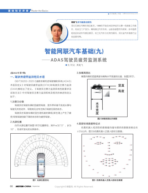
2.光源位置 白天光源位置可按图1所示位置移动,其中α为7.5°,β为10°,形成可变化的光照条件。
◆文/河北 周晓飞智能网联汽车基础(九)——ADAS驾驶员疲劳监测系统图1 光源位置变化 3.张嘴高宽比嘴唇内缘的竖直高度与嘴角水平宽度的比值,如图2所示。
图2 张嘴高宽比示意图4.面部标准数据特征点 仿真机器人检测到的数据值均值与提供的数据误差应在±5%以内,图3为仿真机器人正面人脸标注数据。
图3 仿真机器人正面人脸标注数据Copyright ©博看网. All Rights Reserved.672022/09·汽车维修与保养二、驾驶员疲劳监测原理驾驶员疲劳监测会在车辆行驶过程中,主要通过车辆相关信息综合判断驾驶员当前的状态,配备驾驶员状态监测摄像头(智能视觉系统,图4的车辆还可结合驾驶员当前面部状态,图5所示为面不信息采集示意图。
进一步判断,当出现驾驶员疲劳或注意力不集中时,及时报警降低道路交通事故风险。
位于汽车座舱内的智能视觉车内摄像头(图6),能够全天候与驾驶员进行智能交互,通过它可实现面部识别同步个性化配置、实时监控驾驶员注意力和疲劳状态、实时检测驾驶员心跳健康状况等。
图4 智能视觉系统(蔚来驾驶员疲劳监测摄像头)图5 面部信息采集示意图图6 智能视觉系统车内摄像头(不同车型的摄像头位置)三、驾驶员疲劳监测功能1.功能要求驾驶员疲劳监测系统应具备监测驾驶员闭眼、头部姿态异常、接打手持电话的功能,可具备监测驾驶员打哈欠、抽烟行为的功能(表1) 。
- 1、下载文档前请自行甄别文档内容的完整性,平台不提供额外的编辑、内容补充、找答案等附加服务。
- 2、"仅部分预览"的文档,不可在线预览部分如存在完整性等问题,可反馈申请退款(可完整预览的文档不适用该条件!)。
- 3、如文档侵犯您的权益,请联系客服反馈,我们会尽快为您处理(人工客服工作时间:9:00-18:30)。
本科生毕业设计 (论文)外文翻译原文标题D e v el op me n t o f S en s o rN ew Te ch n ol o gy译文标题传感器新技术的发展作者所在系别xxxx作者所在专业xxxx作者所在班级xxx作者姓名xxx作者学号xx指导教师姓名xxx指导教师职称xxx完成时间2012 年 3 月北华航天工业学院教务处制译文标题传感器新技术的发展原文标题D e v el op me n t of S en so r N ew Tec h n ol og y作者Arai Yasuo 译名新井康夫国籍日本原文出处Japan Technology Information传感器新技术的发展传感器是一种能将物理量、化学量、生物量等转换成电信号的器件。
输出信号有不同形式,如电压、电流、频率、脉冲等,能满足信息传输、处理、记录、显示、控制要求,是自动检测系统和自动控制系统中不可缺少的元件。
如果把计算机比作大脑,那么传感器则相当于五官,传感器能正确感受被测量并转换成相应输出量,对系统的质量起决定性作用。
自动化程度越高,系统对传感器要求越高。
在今天的信息时代里,信息产业包括信息采集、传输、处理三部分,即传感技术、通信技术、计算机技术。
现代的计算机技术和通信技术由于超大规模集成电路的飞速发展,而已经充分发达后,不仅对传感器的精度、可靠性、响应速度、获取的信息量要求越来越高,还要求其成本低廉且使用方便。
显然传统传感器因功能、特性、体积、成本等已难以满足而逐渐被淘汰。
世界许多发达国家都在加快对传感器新技术的研究与开发,并且都已取得极大的突破。
如今传感器新技术的发展,主要有以下几个方面:利用物理现象、化学反应、生物效应作为传感器原理,所以研究发现新现象与新效应是传感器技术发展的重要工作,是研究开发新型传感器的基础。
日本夏普公司利用超导技术研制成功高温超导磁性传感器,是传感器技术的重大突破,其灵敏度高,仅次于超导量子干涉器件。
它的制造工艺远比超导量子干涉器件简单。
可用于磁成像技术,有广泛推广价值。
利用抗体和抗原在电极表面上相遇复合时,会引起电极电位的变化,利用这一现象可制出免疫传感器。
用这种抗体制成的免疫传感器可对某生物体内是否有这种抗原作检查。
如用肝炎病毒抗体可检查某人是否患有肝炎,起到快速、准确作用。
美国加州大学巳研制出这类传感器。
传感器材料是传感器技术的重要基础,由于材料科学进步,人们可制造出各种新型传感器。
例如用高分子聚合物薄膜制成温度传感器;光导纤维能制成压力、流量、温度、位移等多种传感器;用陶瓷制成压力传感器。
高分子聚合物能随周围环境的相对湿度大小成比例地吸附和释放水分子。
高分子电介常数小,水分子能提高聚合物的介电常数。
将高分子电介质做成电容器,测定电容容量的变化,即可得出相对湿度。
利用这个原理制成等离子聚合法聚苯乙烯薄膜温度传感器,其有以下特点:测湿范围宽;温度范围宽,可达-400℃~+1500℃;响应速度快,小于1S;尺寸小,可用于小空间测湿;温度系数小。
陶瓷电容式压力传感器是一种无中介液的干式压力传感器。
采用先进的陶瓷技术和厚膜电子技术,其技术性能稳定,年漂移量小于0.1%F.S,温漂小于±0.15%/10K,抗过载强,可达量程的数百倍。
测量范围可从0到60mpa。
德国E+H公司和美国Kahlo公司产品处于领先地位。
光导纤维的应用是传感材料的重大突破,其最早用于光通信技术。
在光通信利用中发现当温度、压力、电场、磁场等环境条件变化时,引起光纤传输的光波强度、相位、频率、偏振态等变化,测量光波量的变化,就可知道导致这些光波量变化的温度、压力、电场、磁场等物理量的大小,利用这些原理可研制出光导纤维传感器。
光纤传感器与传统传感器相比有许多特点:灵敏度高,结构简单、体积小、耐腐蚀、电绝缘性好、光路可弯曲、便于实现遥测等。
光纤传感器日本处于先进水平。
如Idec Izumi公司和Suns公司。
光纤传感受器与集成光路技术相结合,加速光纤传感器技术的发展。
将集成光路器件代替原有光学元件和无源光器件,使光纤传感器有高的带宽、低的信号处理电压,可靠性高,成本低。
半导体技术中的加工方法有氧化、光刻、扩散、沉积、平面电子工艺,各向导性腐蚀及蒸镀,溅射薄膜等,这些都已引进到传感器制造。
因而产生了各种新型传感器,如利用半导体技术制造出硅微传感器,利用薄膜工艺制造出快速响应的气敏、湿敏传感器,利用溅射薄膜工艺制压力传感器等。
日本横河公司利用各向导性腐蚀技术进行高精度三维加工,制成全硅谐振式压力传感器。
核心部分由感压硅膜片和硅膜片上面制作的两个谐振梁结成,两个谐振梁的频差对应不同的压力,用频率差的方法测压力,可消除环境温度等因素带来的误差。
当环境温度变化时,两个谐振梁频率和幅度变化相同,将两个频率差后,其相同变化量就能够相互抵消。
其测量最高精度可达0.01%FS。
美国Silicon Microstructure Inc.(SMI)公司开发一系列低价位,线性度在0.1%到0.65%范围内的硅微压力传感器,最低满量程为0.15psi(1KPa),其以硅为材料制成,具有独特的三维结构,轻细微机械加工,和多次蚀刻制成惠斯登电桥于硅膜片上,当硅片上方受力时,其产生变形,电阻产生压阻效应而失去电桥平衡,输出与压力成比例的电信号.象这样的硅微传感器是当今传感器发展的前沿技术,其基本特点是敏感元件体积为微米量级,是传统传感器的几十、几百分之一。
在工业控制、航空航天领域、生物医学等方面有重要的作用,如飞机上利用可减轻飞机重量,减少能源。
另一特点是能敏感微小被测量,可制成血压压力传感器。
中国航空总公司北京测控技术研究所,研制的CYJ系列溅谢膜压力传感器是采用离子溅射工艺加工成金属应变计,它克服了非金属式应变计易受温度影响的不足,具有高稳定性,适用于各种场合,被测介质范围宽,还克服了传统粘贴式带来的精度低、迟滞大、蠕变等缺点,具有精度高、可靠性高、体积小的特点,广泛用于航空、石油、化工、医疗等领域。
集成传感器的优势是传统传感器无法达到的,它不仅仅是一个简单的传感器,其将辅助电路中的元件与传感元件同时集成在一块芯片上,使之具有校准、补偿、自诊断和网络通信的功能,它可降低成本、增加产量,美国LUCAS、NOVASENSOR公司开发的这种血压传感器,每星期能生产1万只。
智能化传感器是一种带微处理器的传感器,是微型计算机和传感器相结合的成果,它兼有检测、判断和信息处理功能,与传统传感器相比有很多特点:具有判断和信息处理功能,能对测量值进行修正、误差补偿,因而提高测量精度;可实现多传感器多参数测量;有自诊断和自校准功能,提高可靠性;测量数据可存取,使用方便;有数据通信接口,能与微型计算机直接通信。
把传感器、信号调节电路、单片机集成在一芯片上形成超大规模集成化的高级智能传感器。
美国HONY WELL公司ST-3000型智能传感器,芯片尺寸才有3×4×2mm3,采用半导体工艺,在同一芯片上制成CPU、EPROM、静压、压差、温度等三种敏感元件。
智能化传感器的研究与开发,美国处于领先地位。
美国宇航局在开发宇宙飞船时称这种传感器为灵巧传感器(Smart Sensor),在宇宙飞船上这种传感器是非常重要的。
我国在这方面的研究与开发还很落后,主要是因为我国半导体集成电路工艺水平有限。
传感器的发展日新月异,特别是80年代人类由高度工业化进入信息时代以来,传感器技术向更新、更高的技术发展。
美国、日本等发达国家的传感器技术发展最快,我国由于基础薄弱,传感器技术与这些发达国家相比有较大的差距。
因此,我们应该加大对传感器技术研究、开发的投入,使我国传感器技术与外国差距缩短,促进我国仪器仪表工业和自化化技术的发展。
D e v el op me n t of S en s o r N ew Tec h n ol og ySensor is one kind component which can transform the physical quantity, chemistry quantity and the biomass into electrical signal. The output signal has the different forms like the voltage, the electric current, the frequency, the pulse and so on, which can satisfy the signal transmission, processing, recording, and demonstration and control demands. So it is the automatic detection system and in the automatic control industry .If automatic Technology is used wider, then sensor is more important. In information age, the information industry includes information gathering, transmission, process three parts, namely sensor technology, communication, computer technology. Because of ultra large scale integrated circuit’s rapid development after having been developed Modern computer technology and communication, not only requests sensor precision reliability, speed of response and gain information content request more and more high but also requests its cost to be inexpensive. The obvious traditional sensor is eliminated gradually because of the function, the characteristic, the volume, the cost and so on. As world develop many countries are speeding up to the sensor new technology’s research an d the development, and all has obtained the enormous breakthrough. Now the sensor new technology development mainly has following several aspects:Using the physical phenomenon, the chemical reaction, the biological effect as the sensor principle therefore the researches which discovered the new phenomenon and the new effect are the sensor technological improving ways .it is important studies to developed new sensor’s the foundation. Japanese Sharp Corporation uses the superconductivity technology to develop successfully the high temperature superconductivity magnetic sensor and get the sensor technology significant breakthrough. Its sensitivity is so high and only inferior in the superconductivity quantum interference component. Its manufacture craft is far simpler than the superconductivity quantum interference component. May use in magnetism image formation technology. So it has the widespread promoted value.Using the immune body and the antigen meets one another compound when the electrode surface. It can cause the electrode potential change and use this phenomenon to be possible to generate the immunity sensor. The immunity sensor makes with this kind of immune body may to some organism in whether has this kind of ant original work inspection. Like may inspect somebody with the hepatitis virus immune body whether contracts the hepatitis, plays to is fast, theaccurate role. The US UC sixth branch has developed this kind of sensor.The sensor material is the important foundation for sensor technology, because the materials science is progressive and the people may make each kind of new sensor For example making the temperature sensor with the high polymer thin film; The optical fiber can make the pressure, the current capacity, the temperature, the displacement and so on the many kinds of sensors; Making the pressure transmitter with the ceramics. The high polymer can become the proportion adsorption and the release hydrogen along with the environment relative humidity size. The high polymer electricity lies between the constant to be small, the hydrogen can enhance the polymer the coefficient of dialectical loss. Making the capacitor the high polymer dielectric medium, determines the electric capacity cape city the change, then obtains the relative humidity. Making the plasma using this principle to gather the legitimate polystyrene film temperature sensor below, it has the characteristic.Measured the wet scope is wide; The temperature range is wide, may reach -400 ℃ ~ +1,500 ℃; The speed of response is quick, is smaller than 1S; The size is small, may use in the small space measuring wet; The temperature coefficient is small.The ceramic electric capacity type pressure transmitter is one kind does not have the intermediary fluid the dry type pressure transmitter. Uses the advanced ceramic technology, the heavy film electronic technology, its technical performance is stable, the year drifting quantity is smaller than 0.1%F.S, warm floats is smaller than ±0.15%/10K, anti- overloads strongly, may reach the measuring range several hundred times. The survey scope may from 0 to 60mpa.German E+H Corporation and the American Kahlo Corporation product is at the leading position.The optical fiber application is send the material significant breakthrough, its uses in most early the optical communication techniques. In the optical communication use discovered works as environmental condition change and so on the temperature, pres-sure, electric field, magnetic field, causes the fiber optic transmission light wave intensity, the phase, the frequency, change and so on the polarization condition, the survey light wave quantity change, may know causes these light wave physical quantity the and so on quantitative change temperature, pressure ,electric field, magnetic field size, uses these principles to be possible to develop the optical fiber sensor. The optical fiber sensor and the traditional sensor compare has many characteristics: Sensitivity high, the structure simple, thevolume small, anti-corrosive, the electric insulation good, the path of rays may be curving, be advantageous for the realization telemeter and so on. Optical fiber sensor Japan is in the advanced level. Like Idec Izumi Corporation and Sun x Corporation. The optical fiber send receiver and the integrated path of rays technology unify, accelerates the optical fiber sensor technology development. Will integrate the path of ray’s component to replace the original optics part and the passive light component; enable the optical fiber sensor to have the high band width, the low signal processing voltage, the reliability high, the cost will be low.In semiconductor technology processing method oxygenation, the photo etc hang, the proliferation, the deposition, the plane electron craft, various guides corrosion and steams plates, the sputtering thin film and so on, these have all introduced to the sensor manufacture. Thus has produced each kind of new sensor, like makes the silicon micro sensor using the semiconductor technology, makes the fast response using the thin film craft the gas to be sensitive, the wet sensitive sensor, the use sputtering thin film craft system pressure transmitter and so on..The Japanese horizontal river company uses various guides’ corrosion technology to carry on the high accuracy three dimensional processing; the system helps the silicon resonance type pressure transmitter. The core partially presses two resonant Liang by the feeling which above the silicon diaphragm and the silicon diaphragm manufactures to form, two resonant Liang's frequency difference correspondence different pressure, measures the pressure with the frequency difference method, may eliminate the error which factor and so on ambient temperature brings. When ambient temperature change, two resonant Liang frequencies and the amplitude variation are same, after two frequency differences, its same change quantity can counterbalance mutually. It’s survey most high accuracy may reach 0.01%FS.American Silicon Microstructure Inc.(SMI) the company develops a series of low ends, linear in 0.1% to 0.In 65% scope silicon micro pressure transmitter, the lowest full measuring range is 0.15psi (1KPa), it makes take the silicon as the material, has the unique three dimensional structure, the light slight machine-finishing, makes the wheat stone bridge many times with the etching on the silicon diaphragm, when above silicon chip stress, it has the distortion, the resistance produces presses the anti- effect but to lose the bridge balance, the output and the pressure becomes the proportion the electrical signal.Such silicon micro sensor is the front technology which now the sensor develops, Its essential feature is the sensitive unit volume is a micron magnitude,Is the traditional sensor several dozens, several 1%. In aspect and so on ind ustry control, aerospace domain, biomedicine has the vital role, like on the airplane the use may reduce the airplane weight, reduces the energy. Another characteristic is can be sensitive is small surveyed, may make the blood pressure pressure transmitter.The Chinese aviation main corporation Beijing observation and control technical research institute, the development CYJ series splashes thanks the membrane pressure transmitter is uses the ion sputtering craft to process the metal strain gauge, it has over come the nonmetallic strain gauge easily the temperature influence insufficiency, has the high stability, is suitable in each kind of situation, is measured the medium scope widely, but also overcame the tradition lowly to glue the precision which the type brought, sluggish big, shortcoming and so on slow change, had the precision high, the re-liability is high, the volume small characteristic, widely used in domain and so on aviation, petroleum, chemical industry, medical service.Integrates the sensor the superiority is the traditional sensor is unable to achieve, it is a simple sensor not merely, it in at the same time the auxiliary circuit part and send the part will integrate on together the chip, will cause it to have the calibration, to compensate, from the diagnosis and the network correspondence function, it might reduce the cost, the gain in yield, this kind of blood pressure sensor which American LUCAS, NOVASENSOR Corporation will develop, each week will be able to produce 10,000.The intellectualized sensor is one kind of belt microprocessor sensor, is achievement which the microcomputer and the sensor unifies, it has at the same time the examination, the judgment and the information processing function, compares with the traditional sensor has very many characteristics: Has the judgment and the information processing function, can carry on the revision, the error to the observed value compensates, thus enhancement measuring accuracy; May realize the multi-sensor multi parameters survey; Has from the diagnosis and from the calibration function, enhances the reliability; The survey data may deposit and withdraw, easy to operate; Has the data communication interface, can and the microcomputer direct communication.The sensor, the signal adjustment electric circuit, the monolithic integrated circuit integration forms ultra large-scale integrated on a chip the senior intelligence sensor. American HONY WELL Corporation ST-3000 intelligence sensor, the chip size only then has 3×4×2mm3, uses the semiconductor craft,makes CPU, EPROM, the static pressure, the differential pressure, the temperature on the identical chip and so on three kind of sensitive units.The intellectualized sensor research and the development, US is at the leading position. American Space Agency when development spaceship called this kind of sensor for the clever sensor (Smart Sensor), on the spaceship this kind of sensor is extremely important. Our country in this aspect research and development also very backward mainly is because our country semiconductor integrated circuit technological level is limited.The sensor’s development is changing day after day since especially the 80's humanities have entered into the high industrialization the information age, sensor techno-logy to renewal, higher technological development. US, Japan and so on developed country sensor technological development quickest, our country because the foundation is weak, the sensor technology compares with these developed countries has the big disparity. Therefore, we should enlarge to the sensor engineering research, the development investment, causes our country sensor technology and the foreign disparity reduces, promotes our country instrument measuring appliance industry and from the technical development.指导教师评语外文翻译成绩:指导教师签字:年月日注:1. 指导教师对译文进行评阅时应注意以下几个方面:①翻译的外文文献与毕业设计(论文)的主题是否高度相关,并作为外文参考文献列入毕业设计(论文)的参考文献;②翻译的外文文献字数是否达到规定数量(3 000字以上);③译文语言是否准确、通顺、具有参考价值。