x-lite网络电话终端使用安装说明V2
亿景通信HS118v2 IPPhone酒店IP话机用户使用说明书

HS118v2 酒店IP话机用户使用说明书广州市亿景通信技术有限公司目录1、入门 (1)技术参数说明 (1)2、话机概览 (2)2.1话机按键和硬件 (2)3、网络接入方式设置 (3)3.1 接入 (3)4、基本功能应用 (3)4.1发出呼叫 (3)4.1.1 简单呼叫 (3)4.1.2 重拨 (4)4.1.3可编程键拨号 (4)4.2.1 手柄/免提应答 (4)4.2.2 自动应答 (4)4.3终止呼叫 (5)4.4保持与恢复呼叫 (5)4.5转移呼叫 (5)4.5.1 咨询转及盲转 (6)4.5.2 呼叫前转 (7)4.6免打扰的使用 (7)5、高级功能应用 (7)Peer-to-Peer模式 (7)6、话机键盘设置 (8)6.1调节音量 (8)6.2话机键盘无法设置项 (8)7、话机Web设置 (9)7.1网络 (9)7.2账号及服务器配置 (13)7.3可编程键 (16)7.4话机设置 (17)7.5通讯录 (22)7.6话机维护 (28)7.7安全设置 (33)8、页面语言设置 (38)1、入门技术参数说明注:以下功能在话机无法操作的,只能WEB下进行操作。
项目HS118v2显示语言网页支持多国语言:如中文、英文、俄语、法语等线路数 2功能键保持键、闪断键、重拨键、数字键Voip协议SIP 2.0网络协议HTTP、BOOTP、FTP、TFTP、IEEE 802.1Q语音编码G.723.1 (5.3K 6.4K b/S)、G.729 A (8Kb/s)、G.711 A/U (64Kb/S)、G.722(64Kb/S)QoS 语音优先标记(TOS);动态抖动缓冲区(Jiffer Buffer);语音侦测(V AD)及舒适背景噪声生成(CNG);回音消除G.168 (32ms)网络接口1个10/100M以太网接口(LAN)静态IP、DHCP自动获取IP语音手柄工作模式呼叫处理功能呼叫等待、转接、保持、挂起、重拨安全密码登陆Web 信令加密语音加密维护运营商TR069支持话机键盘设置Web维护所有数据Telnet维护HTTP/TFTP/FTP Auto provision自动升级/TR069电源外部交流电源适配器(5V DC)支持PoE IEEE 802.af物理规格工作温度:0℃ ~ 60℃相对湿度:10% ~ 95%产品认证CE、FCC、RoHS2、话机概览2.1话机按键和硬件从下图,您可以了解到HS118v2话机的按键及硬件。
F2X16 V2 系列 IP MODEM 使用说明书
F2X16V2系列IP MODEM 使用说明书此说明书适用于下列型号产品:客户热线:400-8838-199电话:+86-592-6300320传真:+86-592-5912735网址:地址:厦门集美软件园三期A06栋11层F2X16V2系列IP MODEM使用说明书文档版本密级V1.0.0产品名称:F2X16V2共32页型号产品类别F2116V2GPRS IP MODEM F2A16V2LTE IP MODEM文档修订记录日期版本说明作者2020-02-24V1.0.0初建ZDM2/31著作权声明本文档所载的所有材料或内容受版权法的保护,所有版权由厦门四信通信科技有限公司拥有,但注明引用其他方的内容除外。
未经四信公司书面许可,任何人不得将本文档上的任何内容以任何方式进行复制、经销、翻印、连接、传送等任何商业目的的使用,但对于非商业目的的、个人使用的下载或打印(条件是不得修改,且须保留该材料中的版权说明或其他所有权的说明)除外。
商标声明Four-Faith、四信、、、均系厦门四信通信科技有限公司注册商标,未经事先书面许可,任何人不得以任何方式使用四信名称及四信的商标、标记。
3/31/314注:不同型号配件和接口可能存在差异,具体以实物为准。
目录第一章产品简介 (6)1.1产品概述 (6)1.3工作原理框图 (7)1.4产品规格 (8)第二章安装 (10)2.1概述 (10)2.2开箱 (10)2.3安装与电缆连接 (10)2.4电源说明 (13)2.5指示灯说明 (13)第三章参数配置 (14)3.1配置连接 (14)3.2参数配置方式介绍 (14)3.3参数配置详细说明 (14)3.3.1配置工具运行界面 (15)3.3.2设备上电 (16)3.3.4中心服务 (22)3.3.5串口 (23)3.3.6无线拔号 (24)3.3.7全局参数 (26)3.3.8设备管理 (27)3.3.9其它功能项 (28)第四章数据传输试验环境测试 (29)4.1试验环境网络结构 (29)4.2测试步骤 (29)5/316/31第一章产品简介1.1产品概述F2X16V2系列IP MODEM 是一种物联网无线数据终端,利用公用蜂窝网络为用户提供无线长距离数据传输功能。
PA168X IAX2 网络电话使用手册说明书

PA168X IAX2网络电话使用手册¾PA168X IP网络电话外观 (2)¾功能按键介绍 (3)¾特性 (4)¾协议、标准 (5)¾使用环境 (5)¾电气指标 (6)¾规格 (6)¾安装 (6)¾设置 (6)¾使用键盘设置 (6)¾使用标准WEB浏览器设置 (9)¾使用Telnet设置 (22)¾PA168X Telnet命令详解 (23)¾PA168X Telnet命令一览 (23)¾固件升级 (37)¾使用 (38)¾ PA168X IP 网络电话外观介绍● 面板示意图(请参见图1.1):图1.1 PA168X 话机面板示意图● 后端与侧面示意图(请参见图1.2):本机IP电话号码 菜单/确认 LCD 显示屏设置 未接来电 已接来电 已拨电话回退 音量 +音量 -电话簿 闪断 保持 转移重拨 免提 呼叫图1.2 PA168X 后端与侧面示意图¾ 功能按键介绍:按 键功 能按 键功 能本机IP挂机状态下,按下此键显示本机IP 地址 未接来电挂机状态下,查阅未接来电。
电话号码 挂机状态下,按下此键显示电话号码已接来电挂机状态下,查阅未接来电。
菜单/确认挂机状态下,按此键输入密码进入菜单模式。
菜单模式下,按此键进入下级及确认。
已拨电话挂机状态下,查阅已拨号码。
设 置 菜单模式下,按此键转换成编辑修改状态。
重 拨 重拨已呼叫号码;回退菜单模式下,按此键回退上级菜单或清除。
免 提 按下此键,在免提模式下通话提起听筒再按下此键,将听筒音量调大;按下免提键再按下此键,将扬声器音量调大。
按下“未接来电”、“已接来电”或“已拨电话”键再按下此键,向后翻页查阅对应记录 。
音量+在菜单模式下,按下此键用于向后翻页查取选项。
拿起听筒再按下此键,将听筒音量调小;按下免提键再按下此键,将扬声器音量调小。
Linkways2_安装操作手册
DOCUMENT NO. 1061868-V1
Page 3 of 20
REV. 001
NOCC NCC NMS
ODU
PVC
QB QPSK
RB RF RFT Rx
SCSI SNMP SSPA
TDMA Tx
UPS UW
VAC VDC VOIP VSWR
Network Operations and Control Center 网络操作与控制中心 Network Control Center 网络控制中心 Network Management System 网络管理系统
6
6. 卫星通信终端入网条件
7
7. LinkWayS2 安装的电源要求
8
8. LinkWayS2 终端的连接
8
9. 电缆长度的选择
12
10. ODU的射频频率计算
12
11. LinkWayS2 安装
14
12. LinkWayS2 入网
17
13. LinkWayS2 性能检查
17
14. LinkWayS2 故障诊断
lbs
Pounds 磅
LED
Light Emitting Diode 二极管指示灯
LNB
Low Noise Block Down Converter 底噪声下变频单元
LO
Local Oscillator 本机振荡器
MF mm MRT Msps MTBF
Multi Frequency 多频 Millimeters 毫米 Master Reference Terminal 主参考终端 Mega-Symbols per Second 千兆符每秒 Mean Time between Failures 平均无故障时间
MRX LTE 快速安装指南说明书
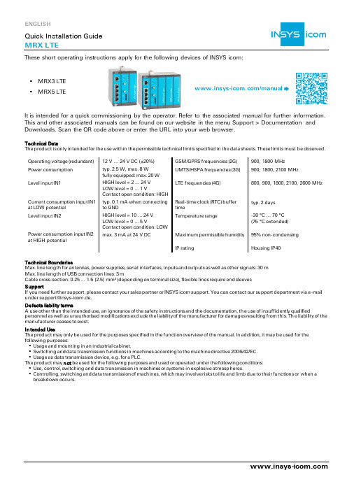
These short operating instructions apply for the following devices of INSYS icom:▪ MRX3 LTE ▪ MRX5 LTE/manualIt is intended for a quick commissioning by the operator. Refer to the associated manual for further information. This and other associated manuals can be found on our website in the menu Support > Documentation and Downloads. Scan the QR code above or enter the URL into your web browser.Technical DataThe product is only intended for the use within the permissible technical limits specified in the data sheets. These limits must be observed.Operating voltage (redundant) 12 V … 24 V DC (±20%) GSM/GPRS frequencies (2G) 900, 1800 MHz Power consumption typ. 2.5 W, max. 8 Wfully equipped: max. 20 W UMTS/HSPA frequencies (3G) 900, 1800, 2100 MHzLevel input IN1HIGH level = 2 ... 24 V LOW level = 0 ... 1 VLTE frequencies (4G)800, 900, 1800, 2100, 2600 MHzCurrent consumption input IN1 at LOW potential typ. 0.1 mA when connecting to GNDReal-time clock (RTC) buffer timetyp. 2 days Level input IN2HIGH level = 10 ... 24 V LOW level = 0 ... 5 VContact open condition: LOW Temperature range-30 °C … 70 °C (75 °C extended) Power consumption input IN2 at HIGH potential max. 3 mA at 24 V DC Maximum permissible humidity 95% non-condensingIP ratingHousing IP40Technical BoundariesMax. line length for antennas, power supplies, serial interfaces, inputs and outputs as well as other signals: 30 m Max. line length of USB connection lines: 3 mCable cross-section: 0.25 … 1.5 (2.5) mm² (depending on terminal size), flexible lines require end sleeves SupportIf you need further support, please contact your sales partner or INSYS icom support. You can contact our support department via e-mail Defects liability termsA use other than the intended use, an ignorance of the safety instructions and the documentation, th e use of insufficiently qualifiedpersonnel as well as unauthorised modifications exclude the liability of the manufacturer for damages resulting from this. Th e liability of the manufacturer ceases to exist.In tended UseThe product may only be used for the purposes specified in the function overview of the manual. In addition, it may be used for the following purposes:▪ Usage and mounting in an industrial cabinet.▪ Switching and data transmission functions in machines according to the machine directive 2006/42/EC. ▪ Usage as data transmission device, e.g. for a PLC.The product may n ot be used for the following purposes and used or operated under the following conditions: ▪ Use, control, switching and data transmission in machines or systems in explosive atmosp heres.▪ Controlling, switching and data transmission of machines, which may involve risks to life and limb due to their functions or when a breakdown occurs.Eject SIM card holder, insert SIM card (Mini-SIM, 2FF)Open the Inline Help using the buttonAll modified data will only be stored in the opened profile after clicking the button and become effective upon clicking theIn Menu Help > Wizards:APNs of popular providers can beVPN under VPN connection and enter Customer name and–VPN, “My VPN Hub” tab). Then, the IP address in the local network will be assigned by the icom Connectivity Suite - VPN.during connection establishment; as soon as an Internet connection has been established, it is illuminated green and the Signal LED flashesAll essential configuration steps are completed with this. Further configuration depends on your specific application. Other frequently required settings are available on the following page.Hereby, INSYS Microelectronics GmbH declares that herein described device types are in compliance with Directives 2014/53/EU and 2011/65/EU. The full text of the EC Declaration of Conformity is available under /manual.。
ZXA10 F411(V2.0)光网络终端 用户手册

任何方式授予阅读者任何使用本手册上出现的任何标记的许可或权利。
本产品符合关于环境保护和人身安全方面的设计要求,产品的存放、使用和弃置应遵照产品
手册、相关合同或相关国法律、法规的要求进行。
如果本产品进行改进或技术变更,恕不另行可以通过中兴通讯技术支持网站
6 安全配置 ...........................................35 6.1 概述 ............................................... 35 6.2 MAC过滤设置 ........................................ 35
软件操作手册LT拨软件客户端操作使用指南VP

软件操作手册L T拨软件客户端操作使用指南V PDocument number【980KGB-6898YT-769T8CB-246UT-18GG08】使用指南目录一、客户端的安装..............................................................1.1 系统要求.............................................................1.2 安装.................................................................二、客户端软件的使用..........................................................2.1 首次使用拨号软件.....................................................2.2 正常使用客户端软件...................................................2.3 拨号过程中的异常情况................................................. 三常见问题...................................................................一、客户端的安装1.1 系统要求操作系统:Windows 2000、Windows XP 、Windows 2003;1.2 安装L2TP客户端软件是免安装的客户端软件,因此用户直接在网络上下载后就直接可以使用,或者是下载升级文件后通过网络安装;用户可以通过运行Connector.exe文件直接使用该客户端软件;如图:或者只下载update.exe文件,通过网络更新获得客户端软件出现更新的提示界面,如图倒计时3秒后,软件自动更新获得客户端软件,如图:更新成功后,弹出软件的应用界面。
潮流网络 WP810 企业级便携式 Wi-Fi 电话 使用手册说明书

深圳市潮流网络技术有限公司WP810企业级便携式Wi-Fi电话用户手册技术支持深圳市潮流网络技术有限公司为客户提供全方位的技术支持。
您可以与本地代理商或服务提供商联系,也可以与公司总部直接联系。
地址:深圳市南山区科技园本区新西路16号彩虹科技大厦4楼邮编:518057网址:客服电话:*************客服传真:*************技术支持热线:4008755751技术支持论坛:/forums网上问题提交系统:/support/submit-a-ticket商标注明和其他潮流网络商标均为深圳市潮流网络技术有限公司的商标。
本文档提及的其他所有商标或注册商标,由各自的所有人拥有。
注意由于产品版本升级或其他原因,本文档内容会不定期进行更新。
除非另有约定,本文档仅作为使用指导,本文档中的所有陈述、信息和建议不构成任何明示或暗示的担保。
目录文档目的 (1)更新日志 (2)固件版本 1.0.1.1 (2)欢迎 (3)产品概述 (4)产品功能 (4)技术规格 (4)安装 (6)包装清单 (6)安装WP810 (7)充电基座 (7)话机 (7)电池信息 (8)WP810按键描述 (9)WP810图标说明 (11)WP810LED状态 (13)WP810话机菜单 (13)WP810键盘输入法 (16)Web界面配置 (18)通过Web浏览器配置 (18)访问Web页面 (18)Web页面语言 (18)保存更改的设置 (19)Web页面访问权限管理 (19)更改用户或管理员密码 (20)更改HTTP/HTTPS访问端口 (21)基本操作 (22)开机/关机 (22)WP810连接Wi-Fi (22)Wi-Fi频段配置 (23)查看WP810状态 (24)帐号状态 (24)系统状态 (24)网络状态 (25)网络统计 (26)设置屏幕亮度和屏幕超时 (27)返回待机页面 (28)注册SIP帐号 (28)通过Web页面注册帐号 (28)通过话机菜单注册帐号 (29)话机设置 (31)选择话机语言 (31)激活/停用免提模式 (31)麦克风静音 (31)调节扬声器和听筒音量 (32)铃声 (32)设置铃声音量 (32)设置话机铃声 (33)日期和时间 (33)重启WP810 (34)呼叫操作 (35)拨打电话 (35)选择通话线路 (35)在通话记录中拨打 (36)在通讯录中拨打 (36)来电接听 (37)自动应答 (37)结束通话 (38)通话保持/恢复 (39)呼叫等待 (39)免打扰(DND) (40)呼叫转移 (40)通话转移 (41)快速拨号 (42)三方会议 (42)语音信箱 (43)设置语音信箱ID (43)播放语音邮件 (44)联系人 (46)本地联系人 (46)通话记录 (48)从通话记录中拨出电话 (48)通话记录选项 (48)通话记录详情 (49)信息 (50)查看短信 (50)新建短信 (50)删除短信 (51)PTT功能 (52)启用PTT模式 (52)发送PTT (53)PTT参数配置 (54)设置 (54)参数 (54)组播 (55)发送组播 (55)组播参数配置 (56)IGMP设置 (57)升级和部署 (58)升级和部署配置 (58)通过Web页面配置 (58)通过TFTP服务器升级 (58)部署和配置文件下载 (59)恢复出厂设置 (60)通过话机菜单恢复出厂设置 (60)通过Web页面恢复出厂设置 (60)体验WP810 (62)图目录图1WP810包装清单 (6)图2充电基座 (7)图3WP810话机安装 (7)图4WP810按键说明 (9)图5WP810菜单结构 (14)图6WP810键盘模式 (16)图7WP810Web GUI语言 (19)图8用户密码 (20)图9Web访问端口 (21)图10主屏幕 (22)图11WP810连至Wi-Fi网络 (23)图12预置SSID (23)图13SIP帐号状态 (24)图14系统状态 (25)图15网络状态 (26)图16网络统计 (26)图17屏幕显示配置 (28)图18帐号状态 (29)图19SIP帐号配置 (30)图20配置话机语言 (31)图21麦克风静音 (32)图22铃声音量 (33)图23来电铃声 (33)图24设置日期和时间 (34)图25重启WP810 (34)图26在通话记录中拨打 (36)图27在通讯录中拨打 (37)图28WP810自动应答 (38)图29自动应答标志 (38)图30通话保持/恢复 (39)图31呼叫等待 (40)图32启用DND (40)图33呼叫转移 (41)图34盲转接 (41)图35配置快速拨号 (42)图36三方会议 (43)图37LCD菜单设置语音信箱ID (43)图38Web界面配置语音信箱访问号码 (44)图39播放语音邮件 (45)图40联系人 (46)图41创建新联系人 (46)图42通话记录 (48)图43通话记录选项 (48)图44WP810通话记录详情 (49)图45查看短信 (50)图46新建短信 (50)图47从联系人新建短信 (51)图48WP810启用PTT功能 (52)图49PTT频道选择 (53)图50发送PTT (53)图51接收PTT (54)图52PTT通道释放 (54)图53开启组播 (55)图54选择组播对讲 (56)图55组播通话 (56)图56IGMP设置 (57)图57WP810通过Web GUI升级 (58)图58LCD菜单恢复出厂 (60)图59WP810Web GUI恢复出厂设置 (61)图60WP810Web GUI确认恢复出厂 (61)表目录表1WP810功能总览 (4)表2WP810技术规格 (4)表3包装清单 (6)表4WP810按键说明 (9)表5WP810图标说明 (11)表6WP810LED状态 (13)表7WP810菜单结构 (15)表8用户权限 (20)表9WP810账号状态说明 (24)表10WP810系统信息说明 (25)表11WP810网络状态说明 (26)表12WP810网络统计说明 (27)表13新联系人参数 (46)文档目的本文档介绍如何使用WP810便携式企业Wi-Fi电话。
X-Lite软电话
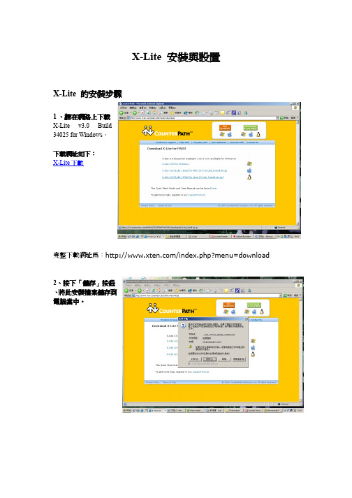
X-Lite 安裝與設置X-Lite 的安裝步驟1 、請在網路上下載X-Lite v3.0Build34025 for Windows,下載網址如下:X-Lite下載完整下載網址為:/index.php?menu=download2、按下「儲存」按鈕、將此安裝檔案儲存到電腦當中。
3、我們先將這一個安裝檔案儲存在「C磁碟機」下4、此時螢幕上變會顯示檔案正在下載5、若螢幕上出現此一對話方塊的話,請按下「關閉」按鈕已完成下載動作。
6、在「C 磁碟機」中找到這一個檔案之後、開啟此一檔案並可以開始進行安裝7、若螢幕出現「安全性警告」、請按下「執行」按鈕。
點這裏8、按下「是(Y)」按鈕點這裏9、按下「Next」按鈕點這裏10、點選「I accepted the agreement 」選項、點選完畢之後、按下「Next」按鈕先選這裏再按這裏11、按下「Next」按鈕點這裏12、按下「Next」按鈕點這裏13、按下「Next」按鈕點這裏14、按下「Next」按鈕點這裏15、按下「Install」按鈕開始進行安裝點這裏16、點選「Launch X-Lite」,然後按下「Finish」按鈕結束安裝先勾這裏再點這裏X-Lite 的設定步驟1、若螢幕上沒有出現X-Lite的程式、各位可以將游標指向右下角的圖示、並按下右鍵,選取「Showthe Phone」就可以在螢幕上看到X-Lite 程式了選這一個點這裏、按右鍵2、要使用X-Lite 之前,必須要先設定帳號、密碼等資料、設定的第一步是先點向下的小箭頭3..開啟「Sip Account」對話方塊、開啟的方法是按下「Sip Account」選項4、此時螢幕上便會出現「SIP」對話方塊, 此時點選「Add」以輸入帳號等資料。
5、將「網路電話帳號」資料填入到「Display Name」欄位裏面6、將「網路電話帳號」資料填入到「UserName」欄位裏面7、將「網路電話設定密碼」資料填入到「Password」欄位裏面(6 位數)顯示「*」字是正常的8、將「網路電話帳號」資料填入到「Authroziation User」欄位裏面9、在「Domain」欄位裏面填入「220.229.62.64:5478」不要填錯、沒有填打不通8選擇「Register with domain」欄位9點擊選擇「domain」10、點擊選擇頂部最右端的「Advanced」在中間的區域有個「Advanced Options」對話方塊,去掉這一欄裏兩個打勾選項11、然後點擊確定回到上一頁面12、按下右下角的「Close」按鈕以結束設定13、螢幕上出現Registering,表示正在註冊14、若設定成功的話、程式便會出現「Ready」的文字、同時也會顯示你的帳號。
LXE MX7 手持式无线终端 说明书

全範圍掃描能力,可 從4英吋至40英呎 的距離內捕捉條碼信息多個一觸式功能鍵,經設置 後,用戶輕輕一按便可啟動 預定的應用功能超光顯示屏,提供 清晰畫面,即使在 倉庫昏暗的角落也 能閱讀資料輕巧便攜、堅固耐用背光按鍵, 可選55獨立數字 字母鍵 或32大數字鍵ToughTalk 語音技術,支持 語音控制的物流操作易握、可移除式的手柄配合用戶手形 設計,使用二隻手指便能觸發掃描器 ,適合長時間掃描動作802.11 a/b/g 無線組件及可選藍牙 提供實時通訊成功掃描條碼震動裝置, 用戶即使在最嘈雜的環境下 亦可確認數據已完成採集可選用保護套, 提高跌地保護指標堅固可靠手持移動終端堅固可靠手持移動終端的代名詞的代名詞的代名詞物流中心的優化產品在倉庫和分銷中心等地方,MX7是進行各種各樣數據採集應用的理想工具,設計上力求使用舒適,輕巧堅固的鎂金屬機身適用於大量掃描操作,其全距離的掃描能力,令使用者可以從近到4英吋,遠到40英呎的距離內掃描條形碼,大大提高了工作效率。
在嘈雜的環境下使用時,可啟動內置震動器,當成功掃描條形碼時能觸動震動器,提醒用戶。
MX7集智能化、運算速度快、彈性於一身,最新Windows® CE 5.0操作系統,配合英特爾® XScale® PXA255處理器,MX7隨時可以投入工作。
結合802.11 a/b/g 無線組件,你已為今日和未來需要實時資料採集的商機做好了準備。
處理器和記憶體 英特爾® XScale PXA255 400MHz 128MB SD 記億體 128MB, 512MB 或 1GB SD 快閃記億體 系統 Windows® CE 5.0 專業版 可選軟件 RF Term® 終端模擬(VT220、TN3270、TN5250) Applock® 可把設備鎖在特定的用戶應用程式 Java Virtual Machine 亞洲字體 Wavelink Avalanche 及 LXE eXpress Config 軟件開發 可從/developer下載 免費SDK 每個API 都提供程式編寫範例 完整的程式應用例子 提供程式開發時經常觸及的問題答案 FAQ 鍵盤 55獨立數字字母鍵 或32大數字鍵 背光按鍵 5個指定功能鍵讓用戶自己定義 防腐塗層 顯示 3.5”(8.8cm) 240×320像素1/4VGA TFT彩色LCD 超亮LED 背光 280 NIT 亮度 耐用觸摸屏及點擊筆 電源供應和管理 2200mAhr,7.2V 可充式鋰離子電池包 後備電池 電池低電量警告 先進及可調的供電管理 介面 藍牙 USB 用戶端 RS232接口 在機充電接口 紅外線IrDA 端口 耳機接口,可用作聲控操作 音量可調的揚聲器 掃描及供電狀態顯示燈 無線組件支援 2.4GHz 802.11b/g 無線卡 2.4/5GHz 802.11a/b/g 無線卡 優化內置雙天線或天線外接頭 思科CCXv4認證 WPA,WPA2 安全制式 可選的藍牙2.0 + EDR w/class 2外觀 尺寸 22.3cm x 8.6cm x 5cm 重量 595克,包括無線組件/電池/掃描器應用環境 操作溫度 -10℃ 到 45℃ 儲存溫度 -20℃ 到70℃ 濕度: 5到95%不凝聚水珠(於40℃) 跌地指標:可承受多次從1.5米高跌落混凝土 地面 ,如外加橡膠保護,高度可達1.8米 防水防塵等級:IEC60529,符合IP65 震動測試:MIL STD 810F認證 幅射 (EMI) FCC Part 15 Subpart B,類 A EN 55022類 A,(CISPR 22) 防干擾 (EMC) EN 55024:1998 安全性 UL 60950, CSA; C22.2 No. 60950; EN 60950, IEC 60950 雷射安全性 CDRH:21 CFR 1040.10; EN 60825-1 及 IEC 60825-1 無線組件認證 FCC Part 15C; Industry Canada RSS 210, 102 EN 300 328 RoHS-compliant 條碼 標準距離掃描器 全範圍掃描器(4英吋至40英呎) ID 及2D Imager 成功掃描震動器 掃描狀態顯示燈 支援所有條碼 選件 尼龍手帶/肩帶/背包4+1電池充電/分析器 橡膠保護套 車載支架 360度可調RAM 支架USB 線(客戶端,ActiveSync 及充電) RS232線(客戶端,ActiveSync 及充電) AC-DC 變壓器,供在機充電使用 觸摸屏保護膜 點擊筆 耳機轉換線 RS232 D9轉換線 配合手形橡膠手柄,二隻手指能觸發掃描器代理商: 資訊坊科技有限公司 香港九龍長沙灣道 883號億利工業 中心8樓802室 電話:(852) 2749 1011 傳真:(852) 8148 3532 網址:/lxe 奔奮科技 (深圳) 有限公司 深圳市福田區彩田南路中深花園B 座 2806室電話:(755) 8358 0500 傳真:(755) 8358 0501網址:LXE 無線解決方案‧ 信心及質量保證以上所有指標如有任何修改,不會另外通知© 2008資訊坊科技有限公司‧版權所有[2008 DEC]。
A1X(W) IP 电话用户手册说明书

A1X(W) IP电话用户手册Version: 2.02017-02-16目录联系 ATCOM (5)1、A1X(W)简介 (6)1.1、接口 (7)1.2、硬件 (7)1.3、软件 (7)1.4、网络 (8)1.5、管理和维护 (9)1.6、协议 (9)1.7、兼容和认证标准 (10)1.8、产品包装 (10)1.9、安装 (11)2、通话功能 (19)2.1、接听电话 (19)2.2、拨打电话 (19)2.3、预拨号 (21)2.4、多线通话 (21)2.5、通话保持 (21)2.6、通话转移 (21)2.7、静音 (22)2.8、三方会议 (22)2.9、结束通话 (24)2.10、语音邮件 (24)3、话机界面 (25)3.1、话机面板 (25)3.2、启动界面 (27)3.3、待机界面 (28)3.4、话机配置 (30)3.4.1、状态信息 (31)3.4.2 、呼叫功能 (33)3.4.3、电话簿 (43)3.4.4、远程电话簿 (48)3.4.5、LDAP (48)3.4.6、历史记录 (50)3.4.7、信息 (53)3.4.8、设置 (54)3.4.9、显示 (75)4、高级功能 (76)4.1、选用编解码 (76)4.2、抓包、升级 (77)4.3、自动更新 (79)4.4、导入、导入配置文件 (81)4.4.1、导出配置文件 (81)4.4.2、导入配置文件 (82)4.5、导入、导出CFG文件 (83)4.6、导出系统日志 (83)4.7、拨号规则 (84)4.7.1、替换规则 (84)4.7.2、立即呼出 (85)4.7.3、地区代码 (86)4.7.4、呼出限制 (87)4.8、TR069 (83)4.9、Action URL (83)4.10、远程控制 (83)5、WI-FI(仅A10W) (88)5.1、 LCD配置 (92)5.2、 WEB界面中配置WIFI (92)5.3、企业WIFI (92)6、常见问题 (94)6.1、如何恢复出厂设置 (94)6.2、在安全模式下升级软件 (95)6.3、如何进行IP拨号 (96)7、故障排除 (97)7.1、话机不能注册到SIP服务器 (97)7.2、话机不能获得IP地址 (97)7.3、通话中只有一方听到声音 (97)8、话机缩略词说明 (98)联系ATCOM公司简介ATCOM是全球领先的VOIP解决方案供应商。
L系列,X系列终端升级方法说明书
L系列、X系列终端升级方法说明书升级流程NCT-2000-XP软件升级流程包括两个步骤,第一步是产品注册,第二步是NCT-2000-XP在线软件升级.注意:只有把全部产品在线注册以后才能进行NCT-2000-XP软件升级。
产品注册上品注后,可以下升件得到技支持。
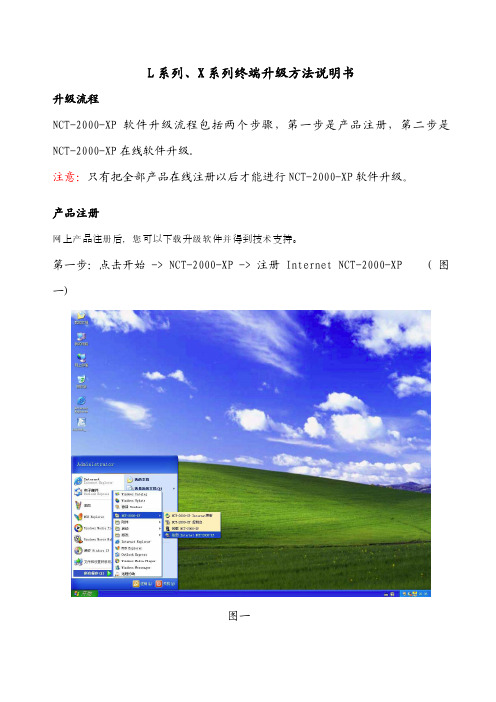
网产册您载级软并术第一步:点击开始 -> NCT-2000-XP -> 注册 Internet NCT-2000-XP (图一)图一第二步:在“欢迎”界面,点击“下一步”按钮。
若您设置了密码保护,请输入您的密码。
(图二)图二第三步:在“收集信息”界面,输入注册用户的相关信息。
完成后,点击“下一步”按钮。
(图三)图三第四步:在“选择方式”界面,选择联机 通过Internet进行注册。
点击“下一步”按钮。
(图四)图四第五步:下一个界面会让您选择注册或注销的序列号。
选择所有要注册或注销的接入终端,接着点击“下一步”按钮。
(图五)注意:这里要把所有的终端全部注册才能进行稍后的网上NCT-2000-XP升级。
图五第六步:在“准备注册”界面,您可以看到您之前输入的用户信息和您选择是否注册的序列号。
确认信息正确后点击“下一步”按钮以完成注册。
(图六)图六第七步:在“在线注册过程”界面,稍等片刻,点击“完成”按钮。
(图七)图七升级终端服务软件第一步:顺利完成注册后,通过在“开始”菜单选择“NCT-2000-XP Internet 更新”(图八)图八第二步:来到更新服务欢迎界面。
点击连接。
图九图九第三步:之后您会看到正在登陆界面,稍等片刻会出现服务器信息以及软件包信息。
点击下载。
图十图十注意!如果您的下载图标是灰色的,说明您有终端未注册,或者您的主机之前用过盗版产品。
图十一图十一第四步:等待升级软件下载,图十二。
图十二按照提示步骤安装,详细步骤请参考用户手册。
图十三图十三如果您升级中遇到问题,请您与北京代表处取得联系。
Asterisk电话会议的实现(原创)

基于Asterisk的电话会议实现一、前言近年来,通信行业的开源项目不断涌现,打破了传统电信设备制造商对电信技术的垄断,为下一代网络(NGN)的发展注入了无限活力。
Asterisk 是一个由Digium公司发起的开放源代码软件,以通用公共许可证(GNU GPL)的授权方式发行。
Asterisk运行在Linux上,以软件的方式实现了(专用分组交换机,PBX)的大部分功能,是一个较全面的通信平台,既支持传统的模拟电话设备和数字电话设备,也支持新兴的基于网络的VoIP语音系统。
在此要讨论的电话会议,就是以Linux为网络操作平台,以Asterisk 作为开发工具,以MySQL作为数据库支持构建一种基于SIP的电话会议系统。
这里提出的基于SIP协议的IP电话系统设计具有投资小、成本低、方便实用、可靠性强、安全性好等优点。
该系统秉承了TCP/UDP协议族的简单性,绝大多数功能都能通过软件实现,且可进行简单的改进,以满足不同的应用和需要。
二、Asterisk在分行的现状目前,苏州分行采用IP电话/模拟电话+Linux PC机+Asterisk PBX+语音网关+PBX+模拟电话的方案。
图中主要功能组件介绍:1. 呼叫控制:Asterisk,IP-PBX系统的智能部分,它负责提供一切传统PBX系统的中心-PBX交换机所能提供的服务。
负责控制所有的呼叫建立和呼叫管理,能轻易提供大部分基本服务(如呼叫保持、呼叫转移、呼叫等待等),以及配置电话的分机号码(Extension Number)、功能按钮、通话管理和路由决策功能。
此外,它还控制所有的PC虚拟电话功能,如语音邮件、统一消息、自动话务员、交互式语音响应(IVR)和自动呼叫分配等。
2. 控制中心:Asterisk,IP-PBX系统的控制组件,包括资源管理系统、计费系统、网管系统、语音信箱等。
3. 信令网关:也是Asterisk,IP-PBX系统的组件之一,提供和其它信令网络的互通功能,可以支持H.323,IAX,SIP,MGCP等的全部或者部分功能。
goxlr-mini快速入门指南说明书

17. 本产品仅适用 于海拔 2000 米以 下地区, 本产品仅 适用于非热带气 候条件下。
法律声明 对于任何因在此说明书提到 的全部或部份描述、 图片或 声明而造成的损失, Music Tribe 不负任何责任。 技术参数和 外观若有更改, 恕不另行通 知。 所有的商标均为其各自所 有者的财产。 Midas, Klark Teknik, Lab Gruppen, Lake, Tannoy, Turbosound, TC Electronic, TC Helicon, Behringer, Bugera, Aston Microphones 和 Coolaudio 是 Music Tribe Global Brands Ltd. 公司的商标或注册 商标。 © Music Tribe Global Brands Ltd. 2022 版权所有。
(11) PHONES - 代 SONY PlayStation 或 Microsoft Xbox 或 HDMI 音频提取器的输入连接。
*Yeti 是的注册商标 Blue Microphones. †PlayStation 是的注册商标或商标 Sony Interactive Entertainment Inc. SONY 是的注册商标 Sony Corporation. ‡Xbox 是 Microsoft Corporation 在美国和/或其他国家的注册商标或商标。
GoXLR 应用程式
必须使用 GoXLR 应用程序才能操作 GoXLR MINI。 GoXLR 应用程序的主要功能包括: • 麦克风均衡、 压缩和门限 • 设置和调整混音器控制 • 更改产品照明 • 直接访问产品手册 • 获得 TC Helicon 支持
最低硬件配置:
基于 PC 的硬件
Elastix安装及常用功能配置(集电子传真、VoIP电话、聊天工具、邮件于一体)
Elastix安装及常用功能配置一、Elastix系统安装二、系统基本配置三、电话配置四、传真配置五、邮件配置六、Openfire安装及配置安装环境:机器类型:兼容机CPU:C1.7G内存:256M硬盘:20GX100P卡两块(一块传真,一块电话)Elastix:0.83一、Elastix系统安装1.1下载Elastix光盘镜像,刻录1.2光盘引导安装,过程比较简单,此处略注意:安装过程会格式化整个硬盘测试使用的版本是0.83新版本0.84存在不能发传真及有时接收传真时会出错的问题二、系统基本配置2.1IP地址配置#netconfigIP:10.10.21.200Mask:255.255.255.0Gateway:10.10.21.1reboot2.2生成Zaptal配置文件#genzaptelconf-c no#ztcft–vvvZaptel Version:1.4.2.1Echo Canceller:MG2Configuration======================Channel map:Channel01:FXS Kewlstart(Default)(Slaves:01) Channel02:FXS Kewlstart(Default)(Slaves:02) 2channels configured.#zttool(查看卡的状态)2.3Zaptal.conf文件更改#vi/etc/asterisk/zapata.conf;usedistinctiveringdetection=yesbusydetect=yesbusycount=5(不加的话可能检测不到挂机信号)2.4sip.conf文件更改(支持视频电话)#vi/etc/asterisk/sip.confvideosupport=yesmaxcallbitrate=384allow=h261allow=h263allow=h263pallow=h264做完以上配置后,重启机器#reboot三、电话配置3.1登陆管理界面,常规配置IE里输入:https://10.10.21.200(登陆后需及时更改密码)默认的用户名跟密码:Web interfaceUsername:adminPassword:palosantoSugarCRMUsername:adminPassword:passwordA2billUsername:adminPassword:mypasswordFlash Operator panelPassword:eLaStIx.2oo7MysqlUsername:rootPassword:eLaStIx.2oo7修改网络参数,DNS、网关、更改语言:更正系统时间:3.2PBX里启用常用的模块选择以下模块(也可以根据自己的需要进行选择),点确认,并应用配置6000,6001…….3.3增加分机6000,6001系统->PBX设置->Extensions->增加SIP分机其它未列出来为默认配置,无需修改按同样的方法增加其它分机3.4系统录音(欢迎词,语音提示….)系统->PBX设置->System Recording->上传语音文件(PCM编码,16位,8000HZ)录音命名为On_line(上班时的录音),保存再上传下班时的录音Off_line上传的语音文件放在/var/lib/asterisk/sounds/custom目录下3.5增加上班时及下班时的IVR系统->PBX设置->IVR->Add IVR,添加以下内容,保存同样的方法增加下班时的IVR(录音时上传了音乐的话,还可以按键点歌,配置如下:)3.6增加Time Conditions系统->PBX设置->Time Conditions,设置如下,保存3.7配置Inbounds Routes(使用Zap 1)系统->PBX 设置->Inbounds Routes 配置如下,保存一个VoIP服务器已可正式使用,如果要让外面的用户也能登陆,需要映射以下端口: TCP:5060UDP:10001-20000其中:TCP端口在/etc/asterisk/sip.conf中定义,用户认证端口:UDP端口在/etc/asterisk/rtp.conf中定义,用户用户间的通话3.8其它电话功能呼叫等待,呼叫转移,电话回拔,电话会议,黑名单,号码查找…..待续…..四、传真配置(5000,5001…….)4.1增加分机(5000,5001系统->PBX设置->Extensions->增加IAX2分机其它默认,创建后,修改5000属性如上右图所示:保存后,同样再增加另一个分机5001(fax1,fax2……)4.2增加虚拟传真(fax1,fax2传真->新建虚拟传真保存,再另外建一个虚拟传真4.3设置传真管理员传真->传真管理员输入管理员邮箱,点改变生效4.4系统录音(传真向导)按照3.4的操作,增加传真向导的录音(哪个部门对应哪个号码),取名fax_guide4.5创建传真IVR系统->PBX设置->IVR增加以下IVR,保存4.6配置Inbounds Routes(使用Zap2)系统->PBX设置->Inbounds Routes配置如下,保存,服务器端配置完毕。
终端安装使用说明

目录1Huawei E5776s (3)1.1安装终端相关程序 (3)1.1.1运行终端驱动程序 (3)1.1.2安装相关端口及网卡 (3)1.1.3安装Hisi UE Agent程序 (4)1.1.4修改APN (5)1.2CDS软件连接终端 (6)1.2.1打开Hisi UE Agent程序 (6)1.2.2使用CDS软件连接终端 (7)1.3可能遇到的问题 (8)2Huawei E3276 (9)2.1安装终端相关程序 (9)2.1.1运行终端驱动程序 (9)2.1.2安装Hisi UE Agent程序 (10)2.2CDS软件连接终端 (10)2.2.1打开Hisi UE Agent程序 (10)2.2.2使用CDS软件连接终端 (11)3QSPOT P1 (12)3.1安装终端相关程序 (12)3.1.1设置转换模式 (12)3.1.2安装相关端口及网卡 (13)3.2CDS软件连接终端 (16)3.3可能遇到的问题 (16)4QSPOT D1 (17)4.1安装终端相关程序 (17)4.2CDS软件连接终端 (18)4.3可能遇到的问题 (19)4.3.1PC机无法自动安装驱动程序时,可手动选择 (19)4.3.2CDS端口无法自动识别时,可手动选择 (19)1Huawei E5776s1.1安装终端相关程序1.1.1运行终端驱动程序1.利用数据线将终端与测试PC连接2.连接终端设备后,系统将识别出一个CD-ROM,点击Auto Run自动运行系统将安装MobileWiFi Web管理程序以及终端驱动,用户可按默认步骤点击下一步至完成即可。
完成后不要断开USB连接。
1.1.2安装相关端口及网卡完成步骤1.1后,PC机操作系统将自动安装终端的COM口及网卡,如下图所示:安装完成后,在正常情况下,设备管理器中应该看到6个“HUAWEI”相关的COM口及一个网卡,如下图所示:至此,Huawei E5776s的驱动程序安装完毕。
Rain Bird ESP-LXIVM 2-Wire Controller说明书

Tech SpecLX-IVM 2-Wire ControllerESP-LXIVM Series ControllersThe ESP-LXI VM 2-Wire Controller has many pow-erful, fl exible and simple to use features, starting with the revolutionary new Integrated Valve Mod-ule with “smart solenoid” that stays in constant communication with the controller to provide ef-fi cient irrigation and advanced diagnostics. The ESP-LXI VM supports up to 60 stations standard or 240 stations with LX-IVM Pro. Up to four 2-Wire paths can be connected, plus fl ow sensing and advanced fl ow management tools that set new industry standards for state-of-the art water man-agement.ApplicationsRain Bird’s ESP-LX I VM Series 2-Wire controllers are designed for the largest and most demanding sites, such as housing or condominium complexes, schools, sports fi elds, parks and public spaces, or large industrial and commercial sites.Easy to UseESP-LXIVM features an extra-large backlit LCD dis-play and soft key text labels for button functions that change depending on the programming step. Easy to InstallThe ESP-LXIVM Controller has a spacious case with multiple-sized knockouts on the bottom and rear of the case for wiring. The door and front panel are removable so the case can be easily mounted to the wall.Controller Features• 60-station capability with standard LX-IVM and 240 with LX-IVM Pro• Flow sensor inputs; up to 5 with LX-IVM and 10 with LX-IVM Pro• Six user-selectable languages, including Eng-lish, Spanish, French, German, I talian and Por-tuguese• Removable front panel is programmable under battery power• Wall-mounted, locking outer casing made of high-impact molded plastic. UV and water re-sistant• Optional metal case and/or metal pedestal, or stainless steel case and/or stainless steel ped-estal• Optional remote water management system available using the IQ4 platform and NCC car-tridgesWater Management Features• Learn Flow utility and fl ow usage totalizer help optimize water usage• FloWatch™ protection for high and low fl ow conditions set by the user • FloManager™ manages hydraulic demand,make full use of available water to turn on asmany stations as possible without exceedingwater supply and reducing the total time tocomplete irrigation cycles.• SimulStations™ allows stations to operate at thesame time; up to 8 with LX-IVM and 16 with LX-IVM Pro• Cycle+Soak™ by station• Rain Delay up to 30 days• 365-Day Calendar Day Off (up to 5 days)• Station Delay by program• Normally Open or Normally Closed MasterValves programmable by station; up to 5 withLX-IVM and 10 with LX-IVM Pro• Optional Weather Sensors are programmableby station to prevent or pause watering; up to4 with LX-IVM and 8 with LX-IVM Pro• Seasonal Adjust by Program or by MonthDiagnostic Features• Alarm light with external case lens• 2-Wire diagnostics to simplify and expeditetroubleshooting• Four isolated wire paths prevent full system fail-ure under a single short• 2-Wire Mapping: Maps the devices to corre-sponding wire paths in the controller to helpquickly fi nd and resolve issues• Trending 12-month electrical history reportsand proactive action• Self-Healing: Automatically detect “fi xes” to wirepath and splice issues and re-start irrigationwithout reliance on manual intervention• Two- Way Communication: With “ntelligent”Valves Modules communication happens bothways enabling key features• Self-Shutoff: Once loss of power is detected, au-tomatically shutoff valve to avoid leaks.Operating Specifi cations• Station Run Time: 0 min. to 96 hrs.• Seasonal Adjust: 0% to 300% (96 hrs. maximumstation run time)• 10 independent programs on the ESP-LX VMand 40 on the ESP-LXIVM Pro• 8 start times per program• Program Day Cycles include Custom days ofthe week, Odd, Odd no 31st, Even, and Cyclicaldates• Manual Station and Manual Program startsSurge ProtectionProper grounding and surge protection is essen-tial for 2-Wire installations. A 2-Wire path must besurge protected and grounded every 500 feet (150meters) or every 15 devices, whichever is smaller.The I VM-SD Line Surge Protector is used for thispurpose.Certifi cationsUL, CUL, CE, CSA, C-Tick, FCC Part 15Electrical Specifi cations• Input required: 120 VAC ± 10%, 60Hz (Interna-tional models: 230 VAC ± 10%, 50Hz or 60Hz)• Power back-up: For the full design life of 10 year,the Lithium coin-cell battery maintains timeand date while nonvolatile memory maintainsprograms• Compatible with Rain Bird commercial valves(PGA, PEB, GB, EFB-CP and BPE series)Dimensions14.32” x 12.69” x 5.50” (36.4 x 32.2 x 14.0 cm)EnvironmentalOperating TemperatureOperating temperature range: 14ºF to 149ºF(-10ºC to 65ºC)Operating HumidityOperating humidity range: 95% max at 40ºF to120ºF (4ºC to 49ºC) in a non-condensing environ-mentStorage TemperatureStorage temperature range: -40ºF to 150ºF (-40ºCto 66ºC)SpecificationsThe ESP-LX I VM Controller combines electro-mechanical and microelectronic circuitry capa-ble of fully automatic or manual operation. The controller shall be housed in a wall-mountable, weather-resistant plastic cabinet with a key-locking cabinet door suitable for either indoor or outdoor installation. The controller shall have the ability to be programmed and operated in any of six languages: English, Spanish, French, German, Italian, & Portuguese. The display shall show programming options and operating in-structions in the chosen language without alter-ing the programming or operation information. The ESP-LXIVM controller shall have a base sta-tion capacity of 60 stations, and the ESP-LXIVM Pro a capacity of up to 240 stations. All stations shall have the capability of independently obey-ing or ignoring a weather sensor as well as using or not using master valves. Station timing shall be from 0 minutes to 96 hours. The controller shall have a Seasonal Adjustment by program which adjusts the station run time from 0 to 300% in 1% increments. The controller shall also have a Monthly Seasonal Adjustment of 0 to 300% by month. Station timing with Seasonal Adjustment shall be from 1 second to 96 hours. The ESP-LXIVM controller shall have 10 separate and independent programs which can have dif-ferent start times, start day cycles, and station run times. The ESP-LXIVM Pro expands program count to 40. Each program shall have up to 8 start times per day for a total of 320 possible start times per day. The programs shall be al-lowed to overlap operation based on user de-fined settings which control the number of si-multaneous stations per program and total for the controller. The controller shall allow up to 8 (or 16) valves to operate simultaneously per program and total for the controller not includ-ing the master valves.The controller shall have a 365-day calendar with Permanent Day Off feature that allows a day(s) of the week to be turned off on any user selected program day cycle. (Custom, Even, Odd, Odd31, & Cyclical). Days set to Perma-nent Day Off shall override the normal repeat-ing schedule and not water on those specified day(s) of the week. The controller shall also have a Calendar Day Off feature allowing the user to select up to 5 dates up to 365-days in the future when the controller shall not start programs. The controller shall incorporate a Rain Delay feature allowing the user to set the number of days the controller should remain off before au-tomatically returning to the auto mode. The controller shall have Cycle+Soak water management software which is capable of op-erating each station for a maximum cycle time and a minimum soak time to reduce water run-off. The maximum cycle time shall not be ex-tended by Seasonal Adjustment.The controller shall incorporate a FloManager feature providing real-time flow, power, and sta-tion management. FloManager shall manage the number of stations operating at any point in time based on water source capacity, station flow rate, number of valves per station; user de-fined simultaneous stations per program and for the controller. FloManager shall incorporate the ability to provide station priorities to deter-mine the order in which stations shall operate. The controller shall ignore the station number and instead operate the highest priority sta-tions first and the lower priority stations last when FloManager is enabled. FloManager shall be an option that is disabled by default and the controller shall operate zones in order of sta-tion number, started with the lowest numbered zone set to irrigate and ending with the highest number zone.The controller shall offer Water Windows for each program. This function sets the allowed start and stop time where watering is allowed.f the watering cannot be completed by the time the Water Window closes, the stations with remaining run time are paused and watering automatically resumes when the Water Window opens the next time.The controller shall include an integrated Flow Smart capabilities with flow sensing functional-ity. The controller shall accept sensor input from 1 - 10 flow sensors with no flow scaling device required. A FloWatch Learn Flow Utility which learns the normal flow rate of each station shall be included. Each time a station runs FloWatch compares the current real-time flow rate to the learned rate and takes user-defined actions if high flow, low flow, or no flow is detected. FloWatch shall automatically determine the lo-cation of the flow problem and isolate the prob-lem by turning off the affected station(s) or mas-ter valve(s). FloWatch shall be compatible with both normally closed and normally open master valves. A Manual Master Valve Water Window shall be provided to coordinate daytime manual watering with the flow sensing. This Water Win-dow shall offer programmable days of the weekand manual watering additional flow rate.Rain Bird Corporation 6991 East Southpoint Road Tucson, AZ 85756Phone : (520) 741-6100Fax: (520) 741-6522Rain Bird Technical Services (800) RAINBIRD (1-800-724-6247)(U.S. and Canada )Rain Bird Corporation 970 West Sierra Madre Ave. Azusa, CA 91702Phone : (626) 812-3400Fax: (626) 812-3411Rain Bird International, Inc.1000 West Sierra Madre Ave.Azusa, CA 91702Phone : (626) 963-9311Fax: (626) 852-7343The Intelligent Use of Water TM Registered trademark of Rain Bird Corporation 2020 Rain Bird Corporation D41657 31JA20ESP-LXIVM Series ControllersRevolutionary 2-Wire Design with Integrated Valve Module (IVM)LX-IVM and LX-IVM Pro• 60 or 240 Fixed Stations• 10 or 40 Programs with 8 Start Times Each • Up to 10 Master Valves and Flow Sensors • Up to 8 Weather Sensors Models:ESP-LX-IVM (60 Station)ESP-LX-IVM PRO (240 Station)Metal Case & Pedestal• Painted steel or stainless steel cases andpedestals are available for free-standing controller applications Models:LXMMLXMM-PED LXMMSS LXMMSS-PEDESP-LXIVM 2-Wire Field DevicesField Devices are installed along the 2-Wire pathto interface with valves and other hardware.IVM-SOL• Interfaces with LX-IVM to control station valves and master valves• Rain Bird WC20 connectors (included with IVM-SOL) to be used for all splices Model:LXIVMSOLNetwork Communications Cartridges• ESP-LX Series controllers can be upgraded to IQ Satellite for control using the IQ PlatformIVM-SD• IVM-SD provides surge protection on the 2-Wire path Model:LXIVMSDIVM-SEN• Interfaces with LX-IVM to control weather sensors or fl ow sensors Model:LXIVMSENIVM-OUT•Interfaces with LX-IVM to manage 3rd party valves and external gear such as pump stations Note : 3rd party valves must have DC latching solenoidModel: LXIVMOUT。
欧文版:MDX系列移动通信设备RLI-38847C安装指南说明书
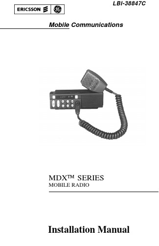
LBI-38847C Mobile CommunicationsMDX™ SERIESMOBILE RADIOInstallation ManualCopyright© October 1992, Ericsson GE Mobile Communications Inc.TABLE OF CONTENTSINTRODUCTION . . . . . . . . . . . . . . . . . . . . . . . . . 3UNPACKING AND CHECKING EQUIPMENT . . . . . . . . . 3PLANNING THE INSTALLATION . . . . . . . . . . . . . . . .4EQUIPMENT REQUIRED . . . . . . . . . . . . . . . . . .6INSTALLATION IN VEHICLES POWERED BYLIQUEFIED (LP) GAS . . . . . . . . . . . . . . . . . . 7MOUNTING LOCATION . . . . . . . . . . . . . . . . . . .7INSTALLATION . . . . . . . . . . . . . . . . . . . . . . . . . . 8RUNNING CABLES . . . . . . . . . . . . . . . . . . . . .8MOUNTING THE RADIO . . . . . . . . . . . . . . . . . .11MICROPHONE HANGER . . . . . . . . . . . . . . . . . .12MICROPHONE . . . . . . . . . . . . . . . . . . . . . . . .14MOBILE OPTIONS INSTALLATION . . . . . . . . . . . . . .14ANTENNA - OPTION PMAN1L (19B209568P5) . . . . . . 14OPTION CABLE KIT - OPTION PMCD7Z(19C851585P14) . . . . . . . . . . . . . . . . . . . . . .15POWER CABLE - OPTION PMCD9A(19B801358P17) . . . . . . . . . . . . . . . . . . . . . . 17MICROPHONE, MIL SPEC - OPTION PMMC3W(19B801499P15) . . . . . . . . . . . . . . . . . . . . . .17NOISE SUPPRESSION KIT - OPTION PMPD1A7(19A148539G1) . . . . . . . . . . . . . . . . . . . . . . 17ALARM (HORN) RELAY KIT - OPTION PMSU1C(19A705499P1) . . . . . . . . . . . . . . . . . . . . . .18EXTERNAL SPEAKER KIT - OPTION PMZM1K . . . .19INT/EXT SPEAKER KIT (PMSU5A),MICROPHONE PA KIT (PMPL3D) . . . . . . . . . . . . . 20OPTION INTERCONNECTION DIAGRAMS . . . . . . . . . . 24This manual is published by Ericsson GE Mobile Communications Inc ., without any warranty. Improvements and changes to this manual necessitated by typographical errors,inaccuracies of current information, or improvements to programs and/or equipment, may be made by Ericsson GE Mobile Communications Inc ., at any time and without notice. Such changes will be incorportated into new editions of this manual. No part of this manual may be reproduced or transmitted in any form or by any means, electronic or mechanical, including photocopying and recording, for any purpose, without the express written permission of Ericsson GE Mobile Communications Inc . 2INTRODUCTIONThis manual contains installation instructions for the MDX Mobile Radioseries and associated accessories. These instructions cover the mounting and cabling of the radio; interconnection diagrams are provided at the back of themanual for reference. Before installation, the radio should be programmed usingan IBM compatible personal computer and the following items:Serial Programming Interface Module Kit . . . . . . . . . . . . . TQ3370 Programming Cable . . . . . . . . . . . . . . . . . . . . . . . . TQ3372 MDX Series Programming Software (EDACS) . . . . . . . . . . TQ3373 orMDX Series Programming Software (GE-MARC only) . . . . TQ3346 UNPACKING AND CHECKING EQUIPMENTWhen ready for installation, carefully unpack the radio and identify each itemin the shipping container as listed below. If damage has occurred to the equipmentduring shipment, file a claim with the carrier immediately. The available options for the MDX Mobile Radio series are covered in Table 1.u MDX Mobile Radiou Microphone . . . . . . . . . . . . . . . . . . . . . . 19B801398P14 used withu Microphone hanger, magnetic hookswitch . . . . . . 19B801398P5oru Microphone . . . . . . . . . . . . . . . . . . . . . . 344A4528P1 used withu Microphone hanger . . . . . . . . . . . . . . . . . . 344A4678P1u Power cable, 9 feet . . . . . . . . . . . . . . . . . . . 19B801358P18 u Mounting bracket kit . . . . . . . . . . . . . . . . . 19A138051G1 1 u Operator’s Manual . . . . . . . . . . . . . . . . . . . LBI-38846u Installation Manual . . . . . . . . . . . . . . . . . . LBI-388473Table 1 - MDX Mobile Radio Series Optional Accessories Option Description Part Number PMAN1L800 MHz roof mount antenna with TNC19B209568P5connectorPMCC9M External speaker cable, 18 inches19A149590P8 PMCD1W External speaker cable, 16 feet, requires19A149590P10option PMZM1K and PMCD7ZPMCD7Z External option cable, 2 feet19C851585P14 PMCD9A Power cable, 18 feet19801358P17 PMLS1F Speaker, MIL-STD-810C & D, 5" x 5", 19A149590P1requires options PMCD7Z & PMCC9MPMMC3X Desk microphone for station use.19C851086P14 PMMC3W Microphone, MIL SPEC19B801499P15 PMMA1L Desk mounting wedge for station use.19C851685G2 PMPD1A Noise suppression kit19A148539G1 PMPS1C Power supply, 120/240V, 50/60 Hz, 13 A.19A704647P2For station use.PMPS1D Power supply, 240V AC, 50/60 Hz, 13 A.19A704647P3For station use.PMSU1C Alarm (horn) relay kit, requires option 19A705499P1PMCD7ZPMZM1K External speaker kit, requires optionPMCD7Z, includes options PMLS1Fand PMCC9MPMMK3D Round pushbutton kit with commonly used344A4254G2legends. Includes button extraction tool.PMSU5A Public Address relay & internal/external speaker19C851585P17 PLANNING THE INSTALLATIONBefore starting, plan the radio installation carefully so that it will be:•safe for the operator and passengers.•convenient for the operator to use.•neat.4Interference with Vehicular Electronics - Electronic fuel injection sys-tems, electronic anti-skid braking systems, electronic cruise control sys-tems, etc., are typical of the types of electronic devices which may be prone to malfunction due to the lack of protection from radio frequency energypresent when transmitting. If the vehicle contains such equipment, consult the dealer for the make of vehicle and enlist his aid in determining if such electronic circuits will perform normally when the radio is transmitting.WARNINGFigure 1 - MDX Components and Mounting Hardware•protected from water damage.•easy to service.•out of the way of auto mechanics.•out of the way of passengers.It is suggested that the radio be installed by one of the many authorized General Electric Service Stations located throughout the United States. These experienced service stations can provide a proper radio installation and make any final adjust-ments that may be needed.5Be careful to avoid damaging some vital part (fuel tank, transmission housing, etc.) of the vehicle when drilling mounting holes. Always check to see how far the mounting screws will extend below the mounting surface before installing.CAUTIONIf pilot holes must be drilled, remove all metal shavings from drilling holes before installing screws.CAUTION Radio installations in vehicles powered by liquefied petroleum gas must conform to the following requirements.WARNINGEQUIPMENT REQUIREDThe equipment required for installing the MDX Mobile Radio is listed below:•Electric drill for drilling mounting holes.•Drills and circle cutters as follows:•No. 31 (1/8-inch) drill for No. 8 self-tapping screws.•No. 27 (9/64-inch) drill for No. 10 self-tapping screws.•5/8-inch drill or circle cutter for power cable.•3/4-inch circle cutter, hole saw or socket punch for antenna (op-tional).•Phillips and flat-blade screwdrivers, and 1/4-inch and 5/16-inch hex-head drivers for mounting screws.• No. 15 Torx® driver (ST0606).•No. 15 Torx® tamper-proof driver (ST0618) if latch security screw (supplied in hardware kit) is used.•No. 25 Torx® driver (STO610).• POZIDRIV® driver for mounting screws.Torx® isa registered trademark of CAMCAR Division TEXTRON. Inc.POZIDRIV® is a registered trademark of Phillips International company.6Figure 2 - Typical Hump Or Dash Mount For passenger safety, mount the radio securely so that the unit will not break loose in the event of a collision. This is especially important in station wagons, vans and similar type installations where a loose radio could be extremely dangerous to the vehicle occupants.WARNINGINSTALLATION IN VEHICLES POWERED BY LIQUEFIED (LP) GASRadio installation in vehicles powered by liquefied petroleum gas with the LP-gas container in the trunk or other sealed-offspace within the interior of the vehicle must conform to the National Fire Protection Association Standard NFPA 58 which requires that:•Space containing radio equipment shall be isolated by a seal from the space containing the LP-gas container and its fittings.•Outside filling connections shall be used for the LP-gas container.•The LP-gas container space shall be vented to the outside of the vehicle.7INSTALLATIONRUNNING CABLESTo assure the feasibility of the planned cable routings. it is suggested that thecables be run before mounting the radio. Be sure to leave some slack in each cablegoing to the radio so that the radio may be pulled out for servicing with the powerapplied and antenna attached.Try to route the cables away from locations where they will be exposed to heat(exhaust pipes, mufflers, tailpipes. etc.). battery acid, sharp edges, or mechanicaldamage or where they will be a nuisance to automobile mechanics. the driver, orpassengers. Keep wiring away from electronic computer modules. other electronic modules and ignition circuits to help prevent interference to these components andradio equipment.In addition. try to utilize existing holes in the fire wall and trunk wall and thechannels above or beneath the doors. Also, channels through door and window columns that are convenient for running cables may be used, unless planning to install rigid or flexible conduit in which to run the cables.Power And Ignition CableThe power cable consists of a red lead, an orange lead, a black lead, a 3 pin systems plug. and a set of fuses and fuse holders to be installed as indicated in Figure 3.To install the power cable, drill a 5/8 inch hole in the firewall for the cable run and insert the rubber grommet. Starting with the plug end of the cable at the location of the radio, run the three cable leads through the hole. Secure the cable at several locations within the engine compartment.To install the fuses:1.Cut off 12 to 18 inches from the red and orange wires.2. Strip back the insulation approximately 3/8 of an inch on each end of the wires.3. Lubricate the wire tips with liquid soap to insert the wires into the fuse holders.Pull the wire ends through the small opening at the end of each fuse holder section and crimp a fuse connector to each wire.8Figure 3 - Power Cable4. Push the prepared fuse connectors into each section of the fuse holders. Placethe fuse into a fuse holder section until it seats within the connector. Connect the fuse holder sections to insure a tight fit and connection.9NOTEIn some installations an additional noise suppression filter such as option PMPD1A (19A148539G1) may be needed for satisfactory performance.NOTEWith some accessory points, the voltage only drops when the ignition switch is in the START position. A connection point should be used where the voltage is completely off when the ignition switch is in the START position.Certain problems may be encountered when accessory equipment is connected to the ignition or accessory lines of the vehicle, where these lines may have large filter capacitors or a leakage path present.If the radio does not turn off within a reasonable amount of time after the ignition is turned off, first try a different accessory or ignition sense pick up point in the vehicle. Many vehicles have more than one circuit that is switched by the ignition switch, and one may be available that does not have large filter capacitors or a leakage path present.If a different pickup point cannot be found, then add a 470-ohm 1-watt resistor from the ignition sense pick point to ground. This will discharge the capacitor(s) or reduce the leakage voltage to a low value. Current drain through this resistor will be minimal (less than 0.03A) when the ignition is switched on.CAUTIONConnect the orange fused lead to the positive (+) battery terminal, and black to the negative (-) battery terminal. Always locate the fuse as close to the battery as possible.Connect the red fused lead to the ignition on" sense point (preferably an "Accessory" point on the fuse panel that is switched on when the ignition switch is in the accessory position and in the "run" position). Locate the fuse as close as possible to the accessory point.10Figure 4 - Mounting DimensionsCoil any surplus cables and secure them out of the waywith the retaining strap provided. Be sure to leave some slack in the cables going to the radio so that it may be pulled out for servicing with power applied.MOUNTING THE RADIOUse the supplied mounting bracket as a template to locate the positions for each of the drill holes. Mount the radio as shown in Figure 5. Be sure to leave enough room at the rear of the radio for the cable connections.11Figure 5 - Mounting Bracket Installation MICROPHONE HANGERMount the microphone hanger in a location convenient to the operator whereit will not interfere with the safe operation of the vehicle orbe a hazard to the vehiclepassengers. The microphone hanger is designed to be mounted with the open end of the mounting button slot pointed upward. The microphone hanger is shown inFigure 6.12NOTEIf mounting on a surface covered with carpet, punch holes with a smallpunch then make a small slit in the carpet, insert a short piece of metaltubing and drill through the tubing.Use the following procedure to mount the microphone hanger:e the hanger as a template to mark the screw locations and drill the smallpilot holes.e the self tapping screws to mount the hanger in an upright position.13Figure 7 - MDX Mobile Radio With MicrophoneMICROPHONEThe microphone connects to the MDX Mobile Radio using a plug found at the end of its attached cable. Match the pins on this plug to the pin socket on the radio and press in the plug being sure not to damage the pins. Once the plug is seated,tighten down the plug using the thumbscrew on the mic connector. To remove the plug reverse this procedure.MOBILE OPTIONS INSTALLATIONANTENNA-OPTION PMAN1L (19B209568P5)Installation instructions for the antenna are packed with the antenna. The antenna must be installed in accordance with good engineering practice for opti-mum results.14A permanent mount type of antenna should be located in the center of the roof of center of rear deck. Glass mounted antennas should be kept as high as possible in the top center of the rear window. Some states have laws restricting vision obstructing items from the windows. Be familiar with local laws before installing glass mount antennas.Try to route the cable away from locations where it will be exposed to heat, sharp edges or mechanical damage, and where it will be out of the way of the driver, passengers or vehicles mechanics. Wherever possible, existing holes in the trunk-wall, and the channels above or beneath doors and window columns should be utilized.Avoid routing the antenna cable near any electronic modules or along side any vehicle wiring.Connect the antenna cable to the TNC connector on the radio being careful not to twist the cable.OPTION CABLE KIT - OPTION PMCD7Z (19C851585P14)The option cable kit brings all option connections from the System Board through the back of the radio to the outside. This cable is required with all external options. Supplied with the option cable is the empty connector housing which plugs into P2 of the option cable. Pins supplied on the ends of the wires of each option (Molex #39-00-0060) are inserted into this connector housing. Refer to the inter-connection diagrams at the back of this manual. See Figure 8 for pin locations. Table 2 lists wire connections and functions.1.Remove the bottom cover of the radio by removing the four bottom coverretaining screws. This also releases the top cover.2.Remove the rubber plug from the option access opening in the rear of the radioadjacent to the power cable. Refer to Figure 3.3.Plug the option cable into J905 on the System Board and push the strain reliefon the cable into the slotted option access opening. Refer to Figure 9.4.Replace the covers and the four bottom retaining screws.15Figure 8- Option Cable Pin Locations16Pins FunctionP2-1A-P2-2SPEAKER LOP2-3SPEAKER HIP2-4MIC HIP2-5SW A+P2-6SERIAL REQUEST (GE-STAR)P2-7PTTP2-8CG DISABLEP2-9SW SPEAKER HIP2-10AUDIO MUTEP2-11VOLUME-SQUELCH HIP2-12MIC LOP2-13RELAYP2-14SPAREPOWER CABLE (18 FEET) - OPTION PMCD9A(19B801358P17)Refer to the power and ignition cable installation section starting on page 8 to install this optional power cord.MICROPHONE, MIL SPEC - OPTION PMMC3W(19B80I499PIS)Refer to the microphone installation section on page 14 to install this optional microphone.NOISE SUPPRESSION KIT - OPTION PMPD1A(19A148539G1)Refer to the noise suppression kit option installation manual that is included with this option and the interconnection diagrams at the back of this manual.17NOTEThe relay contact make/break current and voltage rating is 30 amps at 16volts.ALARM (HORN) RELAY KIT - OPTION PMSUIC (19A705499P1)Requires the use of option cable kit - option PMCC3N. The alarm relay kit option consists of the following items:(1) Relay (19A149299P1)(1) Fuse holder(1) Fuse, 1 amp, 250 volt4 feet red wire, AWG #18 with Ring Tongue Terminal for 3/8 stud 6 feet black wire, AWG #18 with Molex #39-00-0060 terminal(5) Insulated 1/4 inch spade tab receptacles(1) Ring Tongue Terminal for 3/8 inch stud(1) #8 x 3/4 long Type A sheet metal screw (1) Nut Plate for #8 screw1.Install the option cable kit - option PMCD7Z in the radio.2.Fasten the relay in the desired location, close to the voltage source, using one #8 x 3/4 inch self-tapping screw.3.Crimp an insulated 1/4 inch spade tab receptacle tO one end of the #18 red wire.Connect the receptacle to relay lug #86. Cut the red lead so the fuse assembly is close to the voltage source. Install the fuse holder. Attach the other end of the fuse lead to the voltage source with appropriate hardware. See Figure 10.4.Insert the black wire with the Molex terminal into pin 13 of the option connector housing supplied with the option cable. Plug the connector into the option cable.5.Crimp an insulated 1/4 inch spade tab receptacle to the other end of the black wire. Connect the receptacle to relay lug #85.6.Connect the horn or light circuit to lugs #30 and #87 (not 87a) using the insulated 1/4 inch spade tab receptacles.18EXTERNAL SPEAKER KIT - OPTION PMZM1K The external speaker kit includes a speaker (option PMLSIF) and an external speaker cable (option PMCC9M). External speaker cable (option PMCD1W) is available for use with this kit to place the external speaker up to 16 feet furtheraway from the radio. Installation of this kit requires the option cable kit - option PMD7Z.1.Mount the speaker so it is directed to the operator but does not cause interfer-ence with his vision. It also should not present a hazard in the event of an accident. The speaker may be mounted on the lower edge of the instrument panel, the fire wall, or above the windshield in some trucks. Use the mounting bracket as a template for locating the mounting holes, and mount the speaker as shown in Figure 11.2.Install the option cable PMCD7Z if not already present.3.Pins are supplied on the ends of the external speaker cable option PMCC9M.Push these pins into sockets 2 and 9 of the connector housing supplied with the option cable. Refer to Figure 8 and Table 2.4.Plug the connector housing into P2 of the option cable.5.Connect the plug end of the external speaker cable to the speaker. If installingthe external speaker cable option PMCDIW connect it between the speaker and the plug end of the external speaker cable option PMCC9M.19INT/EXT SPEAKER KIT (PMSU5A)MICROPHONE PA KIT (PMPL3D)These two options permit the selection of an external speaker. Option PMSU5A permits the selection of the internal speaker or the external speaker for receive audio. Option PMPL3D allows the external speaker to be a PA speaker by using the microphone (PC programmed). When these two options are installed, the PWB run from HL6-HL7 on the System Board must be cut.20212223(19D904133, Sh. 1, Rev. 3)OPTION INTERCONNECTION DIAGRAM24(19D904133, Sh. 1, Rev. 3)OPTION INTERCONNECTION DIAGRAM25OPTION INTERCONNECTION DIAGRAM(19D904133, Sh. 3, Rev. 2)26(19D904133, Sh. 3, Rev. 2)OPTION INTERCONNECTION DIAGRAM27Printed in U.S.A.。
X-lite使用说明书

X-l i t e使用说明书-CAL-FENGHAI.-(YICAI)-Company One1X-Lite详细使用说明第一步:下载软件(请到本站网络电话下载中心下载)第二步:安装。
根据提示,点击“next”,到如下界面时,选择“I accept the agreement”根据提示点击“next”往下安装,直到看到如下界面,表示安装完成。
点击“finish”第三步:点击“Finish”,稍等片刻,将会自动出现X-Lite软件界面,并且会弹出下面界面:点击选择“否”第四步:点击“否”以后,将会出现以下界面:请点击“Close”,关闭此方框。
第五步:申请网络电话帐号(如果已经申请了网络电话帐号和密码的,则无需重复申请,直接根据以下步骤进行)第六步:网络电话帐号申请完成后,打开X-lite程序,对着软件,单击鼠标右键,将会出现如下界面:选择第二项“Sip Account Settings…”,点击进去。
第七步:将会出现以下界面:点击“Add…”选项,将会出现以下界面:上述红色方框内填写如下(非常重要,切莫复制粘贴,请手动输入)Display Name:1***** (您申请的网络电话帐号)User Name:同上Password:****** (您申请的网络电话密码,同网络电话帐号一起发放)Authorization user name:1***** (您申请的网络电话帐号)Domain:(切莫修改)第八步:填写完整,检查准确无误,请点击“确定”,将会出现以下对话框:点击“Close”,就完成了。
当您见到以下界面时,证明您已成功安装并设置了您的X-lite网络电话,您可以正常的使用软件了(注意:如要拨打电话,需要先充值)。
